Technical Field
-
The present invention relates to a
transmitting apparatus and a transmitting method
for use in a mobile communication system.
Background Art
-
In a mobile communication system, because of
arrival of a plurality of transmitted waves at a
receiver after being reflected and diffracted and
movement of the receiving apparatus itself,
amplitude and phase of signals received at the
receiver are drastically varied.
-
In the mobile communication system, it is
necessary to compensate for variations in amplitude
and phase of received signals at the receiver in
order to keep communication quality well. The
similar compensation is also required at the time
of performing processing such as synchronous
detection, delay detection, and the like.
-
As a method for compensating for variations in
amplitude and phase of received signals, there is
generally used a method in which variations in
amplitude and phase of a channel are estimated by
an adaptive equalizer to shape the waveforms of
received signals adaptively and to reduce influence
of interference between signals.
-
However, in the case where the channel
variation is considerably fast due to high-speed
fading, the channel estimation by the adaptive
equalizer cannot sufficiently follow the variation
in the channel, causing a problem in which an error
rate characteristic is deteriorated.
Disclosure of Invention
-
It is an object of the present invention is to
provide a transmitting apparatus and a transmitting
method in which an adaptive equalizer can hold
sufficient following performance so that
communication quality can be satisfactorily
maintain without increasing the number of apparatus
components even in the case where the channel
variation is considerably fast due to high-speed
fading.
-
This object can be achieved by performing
transmission after increasing a symbol rate when the
channel variation is considerably fast due to
high-speed fading and making the channel variation
between symbols or in a burst relatively minute.
Brief Description of Drawings
-
- FIG. 1 is a block diagram illustrating the
configuration of a transmitting apparatus and that
of a receiving apparatus according to a first
embodiment of the present invention;
- FIG. 2A is a view illustrating a frequency band
corresponding to a symbol rate;
- FIG. 2B is a view illustrating a frequency band
corresponding to a symbol rate;
- FIG. 3A is a view illustrating the relationship
between the symbol rate and a channel variation;
- FIG. 3B is a view illustrating the relationship
between the symbol rate and a channel variation;
- FIG. 4 is a block diagram illustrating the
configuration of a transmitting apparatus and that
of a receiving apparatus according to a second
embodiment of the present invention;
- FIG. 5 is a view illustrating the relationship
between the symbol rate and a BER characteristic;
and
- FIG. 6 is a block diagram illustrating the
configuration of a transmitting apparatus and that
of a receiving apparatus according to a third
embodiment of the present invention.
-
Best Mode for Carrying Out the Invention
-
The following will explain embodiments of the
present invention with reference to the drawings
accompanying herewith.
(First embodiment)
-
FIG. 1 is a block diagram illustrating the
configuration of a transmitting apparatus and that
of a receiving apparatus according to a first
embodiment of the present invention.
-
In a transmitting apparatus 100 illustrated in
FIG. 1, a channel variation estimating section 101
estimates a channel variation quantity between the
transmitting apparatus 100 and a receiving
apparatus 200, and outputs an estimated result to
a symbol rate determining section 102. It is noted
that a channel variation estimating method includes
a method for measuring a reception level of received
signal by the receiving apparatus (not shown), which
is mounted on a base station apparatus with the
transmitting apparatus 100, to perform estimation
based on the measured result.
-
The symbol rate determining section 102
determines a symbol rate based on the estimated
channel variation quantity. Then, the symbol rate
determining section 102 outputs a signal indicative
of the determined symbol rate to a frame structuring
section 103, a baseband modulating section 104, a
band variable filter 105, and a synthesizer 106.
-
The frame structuring section 103 performs
frame structuring process in which a frame length
is determined based on the determined symbol rate,
transmitting data is divided into frames, and a
control signal such as a pilot symbol and the like
is inserted into each frame.
-
The baseband modulating section 104 modulates
an output signal of the frame structuring section
103 to a baseband signal based on the determined
symbol rate. The band variable filter 105 forms a
filter based on the determined symbol rate, and
restricts a transmitting band of an output signal
of the baseband modulating section 104.
-
The synthesizer 106 controls a central
frequency of a carrier wave based on the determined
symbol rate, and outputs the carrier wave of the
corresponding central frequency to a multiplying
section 107. Here, as illustrated in the frequency
band of FIGS. 2A and 2B, the synthesizer 106 makes
a central frequency fc2 where the symbol rate is low
different from a central frequency fc1 where the
symbol rate is high to be tilted toward one side of
an allowable bandwidth to which a frequency band is
allocated. This makes it possible to improve
frequency use efficiency as an overall system.
-
It is noted that FIG.2A indicates the frequency
band when the symbol rate is high, and FIG. 2B
indicates the frequency band when the symbol rate
is low.
-
The multiplying section 107 multiplies the
output signal of a band variable filter 105 by the
carrier wave outputted from the synthesizer 106. A
BPF (Band Pass Filter) 108 passes only an output
signal component contained in a given frequency band
among output signal components of the multiplying
section 107. A transmitting antenna 109 radio
transmits an output signal of BPF 108 to the
receiving apparatus 200.
-
In the receiving apparatus 200 illustrated in
FIG. 1, a receiving antenna 201 receives a signal
transmitted from the transmitting apparatus 100.
BPF 202 passes only a component contained in a given
frequency band among output signal components
received by the receiving antenna 201.
-
A symbol rate detecting section 203 detects a
symbol rate of the received signal, and outputs a
signal indicative of the symbol rate to a
synthesizer 204, a band variable filter 206, a
baseband demodulating section 207, and an adaptive
equalizer 208. As a method for detecting the symbol
rate, there is a method in which the transmitting
apparatus 100 multiplexes information of the symbol
rate into transmitting data to detect information
of symbol rate fro the demodulated received signals,
and a method in which the transmitting apparatus 100
demodulates the received signals with a symbol rate
as a candidate to estimate a symbol rate from the
demodulation result.
-
The synthesizer 204 controls a central
frequency of a carrier wave based on the detected
symbol rate, and outputs the carrier wave of the
corresponding central frequency to a multiplying
section 205. The multiplying section 205 multiplies
the output signal of BPF 202 by the carrier wave
outputted from the synthesizer 204.
-
The band variable filter 206 forms a filter
based on the detected symbol rate, and restricts the
band of an output signal of the multiplying section
205 to generate a baseband signal. A baseband
demodulating section 207 demodulates the baseband
signal outputted from the band variable filter 206
based on the detected symbol rate.
-
An adaptive equalizer 208 performs equalizing
process in which the waveform of the output signal
of the baseband demodulating section 207 is shaped
to reduce influence of interference between signals,
and extracts received signal. Even if a delay wave
exists, the channel estimation is performed to make
it possible to estimate the corresponding delay wave
and equalize it if the delay wave is within an
equalization-capable range.
-
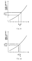
An explanation will be next given of the
relationship between the symbol rate and the channel
variation using FIGS. 3A and 3B. A horizontal axis
in each of FIGS. 3A and 3B indicates time, and a
vertical axis is a phase variable quantity. FIG. 3A
shows a case in which the symbol rate is low, and
FIG. 3B shows a case in which the symbol rate is high.
-
In the case where the symbol rate is low as
illustrated in FIG. 3A, transmitting time Ts1 per
one symbol becomes long and a phase variable
quantity Δ 1 becomes large during this time. While,
in the case where the symbol rate is high as
illustrated in FIG. 3B, transmitting time Ts2 per
one symbol becomes short and a phase variable
quantity Δ 2 becomes small during this time. Though
the above explained the phase variable quantity of
the channel, the same can be applied to time
variation relating to amplitude.
-
Thus, since the symbol rate is increased to
lessen the channel variable quantity relatively,
the symbol rate of the transmitting signal is
increased when the channel variable quantity is
large, making it possible for the adaptive equalizer
of the receiving apparatus to hold sufficient
following performance.
-
Similarly, since the symbol rate is increased
to delay variations in time relatively, it is
possible to compensate for variations in time in
connection with processing such as synchronous
detection of the receiving apparatus, delay
detection, and the like. It is also possible to
compensate for variations in time in connection with
phase rotation due to a frequency offset.
-
Here, it is assumed that the symbol rate
determining section 102 determines a symbol rate
such that the product of transmitting time Ts per
one symbol, namely, the reciprocal of symbol rate
and the channel variable quantity fD becomes a
constant value. This makes it possible to determine
an appropriate symbol rate by a simple calculation
processing.
-
Moreover, since the signal can be transmitted
for a short time when the symbol rate is high, the
transmitting apparatus 100 may transmit the signal
in only a section with a high reception level.
-
This makes it possible to reduce power
consumption and to increase channel use efficiency
as an overall system.
(Second embodiment)
-
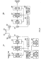
FIG. 4 is a block diagram illustrating the
configuration of the transmitting apparatus and
that of the receiving apparatus according to a
second embodiment of the present invention. In the
transmitting apparatus and the receiving apparatus
illustrated in FIG. 4, the same reference numerals
as those of FIG. 1 are added to the configuration
parts common to FIG. 1, and the explanation is
omitted.
-
In FIG. 4, the transmitting apparatus 100
adopts the configuration in which the channel
variation estimating section 101 and symbol rate
determining section are deleted from FIG. 1 and a
demodulating section 401 and a symbol rate
extracting section 402 are added to FIG. 1. Moreover,
the receiving apparatus 200 adopts the
configuration in which the symbol rate detecting
section 203 is deleted from FIG. 1 and a channel
variation estimating section 301, a symbol rate
determining section 302 and a demodulating section
303 are added to FIG. 1. In FIG. 4, it is noted that
the antenna 109 and the antenna 201 serve as both
a transmitting antenna and a receiving antenna.
-
The channel variation estimating section 301
estimates a channel variable quantity of received
signals, and outputs a signal indicative of a
channel variable quantity to the symbol rate
determining section 302. The symbol rate
determining section 302 determines a symbol rate
based on the estimated channel variable quantity,
and outputs a signal indicative of a symbol rate to
the demodulating section 303. The demodulating
section 303 demodulates the signal indicative of the
symbol rate and transmits it to the antenna 201.
-
A demodulating section 401 demodulates a
signal indicative of a symbol rate received by the
antenna 109,and outputs it to a symbol rate
extracting section 402. The symbol rate extracting
section 402 extracts the symbol rate from the
demodulated signal, and outputs a signal indicative
of the extracted symbol rate to the frame
structuring section 103, the baseband modulating
section 104, the band variable filter 105, and the
synthesizer 106.
-
Thus, the receiving apparatus determines the
symbol rate and the transmitting apparatus
transmits transmitting data in accordance with the
symbol rate determined by the receiving apparatus.
This makes it possible to transmit the symbol rate
at which the receiving apparatus can decode easiest.
-
In the case where the receiving apparatus 200
is integral with the transmitting apparatus,
information indicative of the symbol rate outputted
from the symbol rate determining section 302 may be
multiplexed into transmitting data to be
transmitted.
(Third embodiment)
-
The first and second embodiments explained the
case in which the symbol rate determining section
102 or the symbol rate determining section 302
determined the symbol rate of transmitting data
based on only the channel variable quantity.
-
However, when the symbol rate is increased even
in the case where the same delay wave is used, the
number of delay symbols is relatively increased and
the number of delay symbols, which can be equalized
by the adaptive equalizer, is fixed by the number
of taps of the adaptive equalizer. For this reason,
in the case where the symbol rate continues to be
increased, the delay wave exceeding the
equalization-capable range exists, causing the
problem in which performance of the adaptive
equalizer is deteriorated.
-
For example, a delay wave with 1µs existing in
the radio channel is a delay wave of one symbol delay
when the symbol rate is 1Msps and a delay wave of
two symbol delay when the symbol rate is 2Msps.
-
In the case where the adaptive equalizer with
5 taps is used, the delay wave up to 4-symbol delay
can equalized but the delay wave with more than 4
symbol delay cannot be equalized.
-
Namely, in the case where the delay wave with
1 µs exists, delay time is within 4 symbols when the symbol
rate is less than 4Msps, so that the adaptive equalizer can
equalize the corresponding delay wave. However, when the
symbol rate is more than 4Msps, the adaptive equalizer cannot
equalize the corresponding delay wave and performance of
the adaptive equalizer is deteriorated.
-
FIG. 5 is a view illustrating the relationship
between the symbol rate and an error rate (BER)
characteristic under environment where a channel
variation with a predetermined quantity and a delay
wave with a predetermined delay time exist.
-
As illustrated in FIG.5, when the number of
delay symbols of the delay wave is within the
equalization-capable range, the channel variable
quantity due to fading relatively becomes small with
an increase in the symbol rate, so that the error
rate characteristic is improved. While, when the
number of delay symbols of the delay wave exceeds
the equalization-capable range, the error rate
characteristic is deteriorated by influence of the
delay wave with the increase in the symbol rate.
-
Accordingly, the third embodiment determines
an optimal symbol rate X whose error rate becomes
minimum by the channel variable quantity and the
delay time of the delay wave.
-
FIG.6 is a block diagram illustrating the
configuration of the transmitting apparatus and
that of the receiving apparatus according to a
second embodiment of the present invention. In the
transmitting apparatus and the receiving apparatus
illustrated in FIG. 6, the same reference numerals
as those of FIG. 1 are added to the configuration
parts common to FIG. 1, and the explanation is
omitted.
-
In FIG. 6, the receiving apparatus 200 has the
same configuration as that of FIG.1, and the
transmitting apparatus 100 adopts the configuration
in which a delay profile generating section 501 is
added to FIG.1.
-
The delay profile generating section 501
generates a delay profile of the signal received by
the receiving apparatus (not shown) mounted on the
base station apparatus together with the
transmitting apparatus 100, and outputs the
generated delay profile to the symbol rate
determining section 102.
-
The symbol rate determining section 102 holds
a reference table that provides a symbol rate whose
error rate becomes minimum from the channel variable
quantity and time delay of the delay wave. Then, the
symbol rate determining section 102 inputs the
channel variable quantity from the variation
estimating section 101, and inputs the delay profile
from the delay profile generating section 501, and
determines a symbol rate based on the reference
table.
-
This determined symbol rate is an optimal
symbol rate at which the receiving apparatus 200 can
decode easiest, and the receiving apparatus 200 can
keep the communication quality satisfactory.
-
Moreover, a table with consideration given to
not only delay time but also a pass model in which
delay time of the delay wave of each pass and the
level are modeled is prepared, and this makes it
possible to select an optimal symbol rate at which
the receiving apparatus 200 can decode easiest more
accurately.
-
Additionally, as illustrated in the second
embodiment, the receiving apparatus determines the
symbol rate and the transmitting apparatus can
transmit transmitting data in accordance with the
symbol rate determined by the receiving apparatus.
In this case, the channel varying section and the
delay profile generating section are added to the
receiving apparatus 200.
-
As is obvious from the aforementioned
explanation, according to the transmitting
apparatus and the transmitting method of the present
invention, the symbol rate can be adaptively changed
in accordance with the measured channel variable
quantity, and this makes it possible for the
adaptive equalizer to hold sufficient following
performance and to maintain communication quality
satisfactory without increasing the number of
apparatus components even in the case where the
channel variation is considerably fast due to
high-speed fading.
-
This application is based on the Japanese
Patent Application No. HEI11-275688 filed on
September 29, 1999, entire content of which is
expressly incorporated by reference herein.
Industrial Applicability
-
The present invention is suitable for use in
a base station apparatus and a communication
terminal apparatus in a mobile communication system
such a cellular phone.