EP1124290A2 - Electrical connector - Google Patents
Electrical connector Download PDFInfo
- Publication number
- EP1124290A2 EP1124290A2 EP01102515A EP01102515A EP1124290A2 EP 1124290 A2 EP1124290 A2 EP 1124290A2 EP 01102515 A EP01102515 A EP 01102515A EP 01102515 A EP01102515 A EP 01102515A EP 1124290 A2 EP1124290 A2 EP 1124290A2
- Authority
- EP
- European Patent Office
- Prior art keywords
- sections
- contact
- connector
- electrical connector
- contact elements
- Prior art date
- Legal status (The legal status is an assumption and is not a legal conclusion. Google has not performed a legal analysis and makes no representation as to the accuracy of the status listed.)
- Withdrawn
Links
Images

Classifications
-
- H—ELECTRICITY
- H01—ELECTRIC ELEMENTS
- H01R—ELECTRICALLY-CONDUCTIVE CONNECTIONS; STRUCTURAL ASSOCIATIONS OF A PLURALITY OF MUTUALLY-INSULATED ELECTRICAL CONNECTING ELEMENTS; COUPLING DEVICES; CURRENT COLLECTORS
- H01R13/00—Details of coupling devices of the kinds covered by groups H01R12/70 or H01R24/00 - H01R33/00
- H01R13/62—Means for facilitating engagement or disengagement of coupling parts or for holding them in engagement
- H01R13/627—Snap or like fastening
- H01R13/6271—Latching means integral with the housing
- H01R13/6272—Latching means integral with the housing comprising a single latching arm
-
- H—ELECTRICITY
- H01—ELECTRIC ELEMENTS
- H01R—ELECTRICALLY-CONDUCTIVE CONNECTIONS; STRUCTURAL ASSOCIATIONS OF A PLURALITY OF MUTUALLY-INSULATED ELECTRICAL CONNECTING ELEMENTS; COUPLING DEVICES; CURRENT COLLECTORS
- H01R13/00—Details of coupling devices of the kinds covered by groups H01R12/70 or H01R24/00 - H01R33/00
- H01R13/648—Protective earth or shield arrangements on coupling devices, e.g. anti-static shielding
- H01R13/658—High frequency shielding arrangements, e.g. against EMI [Electro-Magnetic Interference] or EMP [Electro-Magnetic Pulse]
- H01R13/6581—Shield structure
- H01R13/6582—Shield structure with resilient means for engaging mating connector
Definitions
- the present invention relates to electrical connectors and, particularly, to an electrical connector having a plurality of contact elements with contact sections arranged laterally.
- An electrical connector of this type is disclosed in Japanese patent application Kokai No. 11-505663.
- This connector comprises a housing with a plug section for plugging with a mating connector and a plurality of contact. elements with contact sections arranged on Lhe front face of the plug section in the widthwise direction of the connector. A pair of lock arms arc provided upper and lower sides of the contact sections for supporting the mating connector. It is frequent that the mating connector is attached to a circuit board so that it. is desired that the height of the connector be small.
- the above connector has the lock members on both the upper and lower sides of the contact sections, increasing the height of the connector.
- the distance between the two lock members is so small that it hardly controls the tilting of the connector when it is plugged with an excessive force.
- an object of the invention to provide an electrical connector that is of low profile yet capable of controlling the tilting of the connector upon forced plugging.
- a connector 40 is mounted on a circuit board P, and another connector 10 is plugged into the connector 40.
- the width of each of the connectors 10 and 40 (in a first direction parallel to the circuit board P and perpendicular to the plugging direction) is made greater than the height thereof (in a second direction perpendicular to the circuit board P).
- the connector 10 has a connector body 11 and a cover member 31 for accommodating the connector body 11.
- the connector body 11 comprises a housing body 13 with a plurality of elongated inner cavities 12 provided in the first direction, a plurality of contact elements 14 put in the inner cavities 12, respectively, and a pair of shield plates 15 and 16 provided on the upper and lower surfaces of the housing body 13, respectively.
- Each inner cavity 12 is enlarged in the second direction for accommodating one of the contact elements 14.
- the width and height of the plug section 17 are made smaller than those of the housing body 13 so that the inner cavities 12 are made smaller in the second direction in the plug section 17 than in the housing body 13 (Fig. 2).
- a pair of protruded sections 18 extend forwardly from the pluq section 17 to not only form a recess 19 therebetween but also guide plugging with the mating connector 40.
- a pair of fine grooves 20 are provided on the upper faces of the protruded sections 18 for receiving lock members 21.
- Each lock member 21 is made substantially flat and has an engaging claw 21A projecting from the upper face of the protruded section 18 (Fig. 3). The engaging claws 21A of Lhe lock members 21 are depressed into the fine grooves 20 by a flexible pressure section 33 that is made by a pair of slits 32 cut in the cover member 31.
- the lower shield plate 16 is made thicker than the upper shield plate 15 for providing strength.
- the shield plate 16 is provided with a protective section 16A made of a metal sheet covering the outer and front sides of the protruded sections 18.
- Each contact element 14 has a U-shaped front contact section 14A, a connection section 14B projecting rearwardly from the housing body 13, and an S-shaped flexible section 14C between them.
- the contact elements 14 include long ground contact elements 14' and short signal contact elements 14".
- the contact sections 14A normally project from the bottom of the recess 19 but when the connector 10 is plugged into the connector 40, they are pushed back to the bottom of the recess 19 by the contact elements of the mating connector 40, with the flexible sections 14C being flexed.
- the connector 40 comprises a housing body 42, a plurality of contact elements 41 supported by the housing body 42, and a shield plate 43 fitted over the housing body 42.
- the housing body 42 has a pair of indented sections 44 for not. only receiving the protruded sections 18 but also forming a raised section 4b therebetween where the contact sections 41A of the contact elements 41 are provided for contact with the contact sections 14A when the raised section 45 are put into the recess 19 of the connector 10.
- the shield plate 43 extend forwardly a little more than the front face of the raised section 45 and outwardly at the front land to form an inlet section 43A. It forms outer walls of the indented sections 44 to guide and support the protruded sections 18 of the connector 10.
- a pair of engaging slits 43B are provided in the upper face of the shield plate 43 for engagement. with the engaging claws 21A of the connector 10 for making lock.
- a pair of spring arms 43D are provided on opposite sides of the shield plate 43 for spring contact with the protective sections 16A, thus making shield connection therebetween, when the protruded sections 18 are fitted in the indented sections 44.
- a plurality of grooves 42A are provided in the front Lace of the raised section 45 for receiving the contact sections 41A of contact elements 41.
- the contact sections 41A have sufficient height and width to make contact with the contact sections 14A of the contact elements 14.
- the width and depth of the grooves 42A are made such that the front end of the connector 10 does not make any contact with the contact sections 41A upon plugging.
- connection sections 41B which are to be soldered to traces of circultry on a circuit board P.
- the shield plate 43 has a pair of downward legs 43C to be put through apertures of the circuit board P for making connection by soldering.
- the connector according to the invention comprises the guiding sections or protruded sections and the indented sections provided on opposite sides of the connector so that not only the height of the connector is minimized but also the tilting of the connector upon plugging is minimized.
- Part of the shield plate covers the guiding section to protect the connector against forced plugging.
Landscapes
- Details Of Connecting Devices For Male And Female Coupling (AREA)
- Coupling Device And Connection With Printed Circuit (AREA)
Abstract
Description
- The present invention relates to electrical connectors and, particularly, to an electrical connector having a plurality of contact elements with contact sections arranged laterally.
- An electrical connector of this type is disclosed in Japanese patent application Kokai No. 11-505663. This connector comprises a housing with a plug section for plugging with a mating connector and a plurality of contact. elements with contact sections arranged on Lhe front face of the plug section in the widthwise direction of the connector. A pair of lock arms arc provided upper and lower sides of the contact sections for supporting the mating connector. It is frequent that the mating connector is attached to a circuit board so that it. is desired that the height of the connector be small.
- However, the above connector has the lock members on both the upper and lower sides of the contact sections, increasing the height of the connector. The distance between the two lock members is so small that it hardly controls the tilting of the connector when it is plugged with an excessive force.
- Accordingly, it is an object of the invention to provide an electrical connector that is of low profile yet capable of controlling the tilting of the connector upon forced plugging.
- The above object is achieved by the invention as claimed in claim 1.
- Embodiments of the invention will now be described by way of example with respect to the accompanying drawings in which:
- Fig. 1 is a partially cutaway, top plan view of a pair of connectors according to an embodiment of the invention;
- Fig. 2 is a sectional view taken along line II-II of Fig. 1;
- Fig. 3 is a partially cutaway, side elevational view of one of the connectors; and
- Fig. 4 is a partially cutaway, top plan view of Lhe connectors showing forced plugging at angles.
-
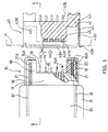
- In Figs. 1 and 2, a
connector 40 is mounted on a circuit board P, and anotherconnector 10 is plugged into theconnector 40. The width of each of theconnectors 10 and 40 (in a first direction parallel to the circuit board P and perpendicular to the plugging direction) is made greater than the height thereof (in a second direction perpendicular to the circuit board P). - As shown in Fig. 2, the
connector 10 has a connector body 11 and acover member 31 for accommodating the connector body 11. The connector body 11 comprises ahousing body 13 with a plurality of elongatedinner cavities 12 provided in the first direction, a plurality ofcontact elements 14 put in theinner cavities 12, respectively, and a pair ofshield plates housing body 13, respectively. - Each
inner cavity 12 is enlarged in the second direction for accommodating one of thecontact elements 14. The width and height of theplug section 17 are made smaller than those of thehousing body 13 so that theinner cavities 12 are made smaller in the second direction in theplug section 17 than in the housing body 13 (Fig. 2). A pair ofprotruded sections 18 extend forwardly from thepluq section 17 to not only form arecess 19 therebetween but also guide plugging with themating connector 40. A pair offine grooves 20 are provided on the upper faces of theprotruded sections 18 for receivinglock members 21. Eachlock member 21 is made substantially flat and has anengaging claw 21A projecting from the upper face of the protruded section 18 (Fig. 3). Theengaging claws 21A of Lhelock members 21 are depressed into thefine grooves 20 by aflexible pressure section 33 that is made by a pair ofslits 32 cut in thecover member 31. - The
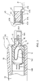
lower shield plate 16 is made thicker than theupper shield plate 15 for providing strength. Theshield plate 16 is provided with aprotective section 16A made of a metal sheet covering the outer and front sides of theprotruded sections 18. Eachcontact element 14 has a U-shapedfront contact section 14A, aconnection section 14B projecting rearwardly from thehousing body 13, and an S-shapedflexible section 14C between them. Thecontact elements 14 include long ground contact elements 14' and shortsignal contact elements 14". Thecontact sections 14A normally project from the bottom of therecess 19 but when theconnector 10 is plugged into theconnector 40, they are pushed back to the bottom of therecess 19 by the contact elements of themating connector 40, with theflexible sections 14C being flexed. - The
connector 40 comprises ahousing body 42, a plurality ofcontact elements 41 supported by thehousing body 42, and ashield plate 43 fitted over thehousing body 42. Thehousing body 42 has a pair of indented sections 44 for not. only receiving theprotruded sections 18 but also forming a raised section 4b therebetween where thecontact sections 41A of thecontact elements 41 are provided for contact with thecontact sections 14A when the raisedsection 45 are put into therecess 19 of theconnector 10. - The
shield plate 43 extend forwardly a little more than the front face of the raisedsection 45 and outwardly at the front land to form aninlet section 43A. It forms outer walls of the indented sections 44 to guide and support theprotruded sections 18 of theconnector 10. A pair ofengaging slits 43B are provided in the upper face of theshield plate 43 for engagement. with theengaging claws 21A of theconnector 10 for making lock. A pair ofspring arms 43D are provided on opposite sides of theshield plate 43 for spring contact with theprotective sections 16A, thus making shield connection therebetween, when theprotruded sections 18 are fitted in the indented sections 44. - A plurality of
grooves 42A are provided in the front Lace of the raisedsection 45 for receiving thecontact sections 41A ofcontact elements 41. As shown in Fig. 2, thecontact sections 41A have sufficient height and width to make contact with thecontact sections 14A of thecontact elements 14. The width and depth of thegrooves 42A are made such that the front end of theconnector 10 does not make any contact with thecontact sections 41A upon plugging. - The end portions of the
contact elements 41 are bent outside thehousing body 42 to formconnection sections 41B which are to be soldered to traces of circultry on a circuit board P. Theshield plate 43 has a pair ofdownward legs 43C to be put through apertures of the circuit board P for making connection by soldering. - How to use the connector will be described below.
- (1) The
connector 40 is attached to the circuit board P. - (2) The cables from other equipment are soldered
to the
connection sections 14B of thecontact elements 14. - (3) The
plug section 17 of theconnector 10 is plugged into theconnector 40 by putting theprotruded sections 18 into the indented sections 44 for guidance, when the guidingsections 43A of theshield plate 43 facilitates insertion of theconnector 10. When theprotruded sections 18 are put in the indented sections 44, theprotective section 16A makes spring contact wit.h thespring arms 43D of theconnector 40 for making shield connection. - (4) When the plugging is completed, the
contact sections 14A of the around contact elements 14' are pushed back by thecontact sections 41A ofLhe contact elements 41, and then thecontact sections 14A of thesignal contact elements 14" are pushed back by thecontact sections 41A of thecontact elements 41. Consequently, the ground contact elements and the signal contact elements make sequential contact with thecontact elements 41 under a predetermined contact pressure by the spring force of theflexible sections 14C. - (5) The
engaging claws 21A of theconnector 10 engage theengaging slits 43B of theconnector 40 to prevent. separation of both the connectors. - (6) To unplug the connector, the
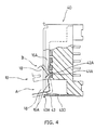
pressure member 33 of theconnector 10 is depressed to flex thelock members 21 for removing theengaging claws 21A from theengaging slits 43B. Under such conditions, it is possible to unplug theconnector 10 from theconnector 40. - (7) Where an attempt is made to plug the connectors at an
angle with an excessive force, the
protruded sections 18 of theconnector 10 and the indented sections 44 of theconnector 40 cooperate to minimise the angle. For example, even if theconnector 10 is tilted or out of position with respect to theconnector 40 in a forced plugging operation as shown by phantom lines A or B in Fig. 4, both of theconnector 10 and thecontact sections 41A are protected by theprotective section 16A and in thegrooves 42A, respectively. -
- As has been described above, the connector according to the invention comprises the guiding sections or protruded sections and the indented sections provided on opposite sides of the connector so that not only the height of the connector is minimized but also the tilting of the connector upon plugging is minimized. Part of the shield plate covers the guiding section to protect the connector against forced plugging.
Claims (7)
- An electrical connector comprising:a housing with a plug section having a width which is greater than a height;a plurality of contact elements with contact sections arranged in said plug section in a widthwise direction of said connector; anda pair of protruded sections or indented sections provided on opposite sides of said connector.
- An electrical connector according to claim 1, which further comprises a shield plate for covering at. least outer side and front faces of said protruded sections for protection.
- An electrical connector according to claim 2, which further comprises a pair of flexible lock members with engaging claws projecting from said housing.
- An electrical connector according to claim 1, wherein said contact elements are provided with flexible sections so that said contact sections are pushed back to a face of said housing by contact sections of said mating connector.
- An electrical connector according to claim 1, which further comprises a shield plate with opposite side walls serving as outer side walls of said indented sections for guiding and supporting side mating connector.
- An electrical connector according to claim 1, wherein said housing has a plurality of fine grooves for receiving contact soctions of said contact elements such that any front corner of said mating connector cannot make contact with said contact sections.
- An electrical connector according to claim 5, wherein said shield plate surrounds said plug section and has a flared front inlet portion.
Applications Claiming Priority (2)
| Application Number | Priority Date | Filing Date | Title |
|---|---|---|---|
| JP2000031369 | 2000-02-09 | ||
| JP2000031369A JP2001223057A (en) | 2000-02-09 | 2000-02-09 | Electric connector |
Publications (2)
| Publication Number | Publication Date |
|---|---|
| EP1124290A2 true EP1124290A2 (en) | 2001-08-16 |
| EP1124290A3 EP1124290A3 (en) | 2002-07-24 |
Family
ID=18556133
Family Applications (1)
| Application Number | Title | Priority Date | Filing Date |
|---|---|---|---|
| EP01102515A Withdrawn EP1124290A3 (en) | 2000-02-09 | 2001-02-05 | Electrical connector |
Country Status (3)
| Country | Link |
|---|---|
| US (1) | US6379187B2 (en) |
| EP (1) | EP1124290A3 (en) |
| JP (1) | JP2001223057A (en) |
Cited By (3)
| Publication number | Priority date | Publication date | Assignee | Title |
|---|---|---|---|---|
| GB2378827A (en) * | 2001-08-17 | 2003-02-19 | Yazaki Corp | Connector with notch to obstruct incorrect counterpart |
| GB2411778A (en) * | 2004-03-02 | 2005-09-07 | Smk Kk | Reinforcing connector using part of shield |
| DE102006020955A1 (en) * | 2006-05-05 | 2007-11-15 | Lumberg Connect Gmbh | press contact |
Families Citing this family (53)
| Publication number | Priority date | Publication date | Assignee | Title |
|---|---|---|---|---|
| FR2769165B1 (en) | 1997-09-26 | 2002-11-29 | Technical Maintenance Corp | WIRELESS SYSTEM WITH DIGITAL TRANSMISSION FOR SPEAKERS |
| FR2781580B1 (en) | 1998-07-22 | 2000-09-22 | Technical Maintenance Corp | SOUND CONTROL CIRCUIT FOR INTELLIGENT DIGITAL AUDIOVISUAL REPRODUCTION SYSTEM |
| FR2781591B1 (en) | 1998-07-22 | 2000-09-22 | Technical Maintenance Corp | AUDIOVISUAL REPRODUCTION SYSTEM |
| FR2805377B1 (en) | 2000-02-23 | 2003-09-12 | Touchtunes Music Corp | EARLY ORDERING PROCESS FOR A SELECTION, DIGITAL SYSTEM AND JUKE-BOX FOR IMPLEMENTING THE METHOD |
| FR2805060B1 (en) | 2000-02-16 | 2005-04-08 | Touchtunes Music Corp | METHOD FOR RECEIVING FILES DURING DOWNLOAD |
| FR2808906B1 (en) | 2000-05-10 | 2005-02-11 | Touchtunes Music Corp | DEVICE AND METHOD FOR REMOTELY MANAGING A NETWORK OF AUDIOVISUAL INFORMATION REPRODUCTION SYSTEMS |
| FR2811114B1 (en) | 2000-06-29 | 2002-12-27 | Touchtunes Music Corp | DEVICE AND METHOD FOR COMMUNICATION BETWEEN A SYSTEM FOR REPRODUCING AUDIOVISUAL INFORMATION AND AN ELECTRONIC ENTERTAINMENT MACHINE |
| FR2814085B1 (en) | 2000-09-15 | 2005-02-11 | Touchtunes Music Corp | ENTERTAINMENT METHOD BASED ON MULTIPLE CHOICE COMPETITION GAMES |
| JP2002373738A (en) * | 2001-06-11 | 2002-12-26 | Molex Inc | Shielded connector with insertion guide |
| US6568961B1 (en) * | 2002-04-29 | 2003-05-27 | Lear Corporation | Wireform contactor assembly |
| US10373420B2 (en) | 2002-09-16 | 2019-08-06 | Touchtunes Music Corporation | Digital downloading jukebox with enhanced communication features |
| US8103589B2 (en) | 2002-09-16 | 2012-01-24 | Touchtunes Music Corporation | Digital downloading jukebox system with central and local music servers |
| US8332895B2 (en) | 2002-09-16 | 2012-12-11 | Touchtunes Music Corporation | Digital downloading jukebox system with user-tailored music management, communications, and other tools |
| US11029823B2 (en) | 2002-09-16 | 2021-06-08 | Touchtunes Music Corporation | Jukebox with customizable avatar |
| US7822687B2 (en) | 2002-09-16 | 2010-10-26 | Francois Brillon | Jukebox with customizable avatar |
| US8584175B2 (en) | 2002-09-16 | 2013-11-12 | Touchtunes Music Corporation | Digital downloading jukebox system with user-tailored music management, communications, and other tools |
| US9646339B2 (en) | 2002-09-16 | 2017-05-09 | Touchtunes Music Corporation | Digital downloading jukebox system with central and local music servers |
| JP3969400B2 (en) | 2004-04-09 | 2007-09-05 | 松下電工株式会社 | connector |
| JP2007103249A (en) * | 2005-10-06 | 2007-04-19 | Japan Aviation Electronics Industry Ltd | Electric connector |
| US9171419B2 (en) * | 2007-01-17 | 2015-10-27 | Touchtunes Music Corporation | Coin operated entertainment system |
| JP4494441B2 (en) * | 2007-07-03 | 2010-06-30 | 日本航空電子工業株式会社 | Electrical connector |
| US10290006B2 (en) | 2008-08-15 | 2019-05-14 | Touchtunes Music Corporation | Digital signage and gaming services to comply with federal and state alcohol and beverage laws and regulations |
| US8849435B2 (en) | 2008-07-09 | 2014-09-30 | Touchtunes Music Corporation | Digital downloading jukebox with revenue-enhancing features |
| JP4849109B2 (en) * | 2008-09-10 | 2012-01-11 | パナソニック電工株式会社 | Receptacle connector and manufacturing method thereof |
| JP4558824B2 (en) | 2008-09-19 | 2010-10-06 | 株式会社アイペックス | Connector device |
| CA2754990C (en) | 2009-03-18 | 2015-07-14 | Touchtunes Music Corporation | Entertainment server and associated social networking services |
| US9292166B2 (en) | 2009-03-18 | 2016-03-22 | Touchtunes Music Corporation | Digital jukebox device with improved karaoke-related user interfaces, and associated methods |
| US9285831B2 (en) | 2009-09-17 | 2016-03-15 | Henge Docks Llc | Docking station for portable electronics |
| US8512079B2 (en) * | 2009-09-17 | 2013-08-20 | Henge Docks Llc | Docking station for an electronic device with improved electrical interface |
| CN105355221A (en) | 2010-01-26 | 2016-02-24 | 踏途音乐公司 | Digital jukebox device with improved user interfaces, and associated methods |
| US8998632B2 (en) | 2010-05-28 | 2015-04-07 | Apple Inc. | Dual orientation connector with external contacts |
| TWM420090U (en) * | 2011-06-16 | 2012-01-01 | Molex Taiwan Ltd | Electrical connection device |
| JP6002770B2 (en) | 2011-09-18 | 2016-10-05 | タッチチューンズ ミュージック コーポレーション | Digital jukebox device with karaoke and / or photo booth functions and related techniques |
| US8708745B2 (en) | 2011-11-07 | 2014-04-29 | Apple Inc. | Dual orientation electronic connector |
| US9293876B2 (en) | 2011-11-07 | 2016-03-22 | Apple Inc. | Techniques for configuring contacts of a connector |
| US9112327B2 (en) | 2011-11-30 | 2015-08-18 | Apple Inc. | Audio/video connector for an electronic device |
| US11151224B2 (en) | 2012-01-09 | 2021-10-19 | Touchtunes Music Corporation | Systems and/or methods for monitoring audio inputs to jukebox devices |
| US9093803B2 (en) | 2012-09-07 | 2015-07-28 | Apple Inc. | Plug connector |
| WO2014040231A1 (en) | 2012-09-11 | 2014-03-20 | Apple Inc. | Connectors and methods for manufacturing connectors |
| US9059531B2 (en) | 2012-09-11 | 2015-06-16 | Apple Inc. | Connectors and methods for manufacturing connectors |
| US9160129B2 (en) | 2012-09-11 | 2015-10-13 | Apple Inc. | Connectors and methods for manufacturing connectors |
| US9325097B2 (en) | 2012-11-16 | 2016-04-26 | Apple Inc. | Connector contacts with thermally conductive polymer |
| US20140206209A1 (en) | 2013-01-24 | 2014-07-24 | Apple Inc. | Reversible usb connector |
| TWI500222B (en) * | 2013-07-12 | 2015-09-11 | Ccp Contact Probes Co Ltd | Connector assembly |
| US9650814B2 (en) | 2013-12-31 | 2017-05-16 | Henge Docks Llc | Alignment and drive system for motorized horizontal docking station |
| US9927838B2 (en) | 2013-12-31 | 2018-03-27 | Henge Docks Llc | Sensor system for docking station |
| CN203760751U (en) * | 2014-02-25 | 2014-08-06 | 番禺得意精密电子工业有限公司 | Electric connector assembly |
| US9727084B2 (en) | 2015-10-23 | 2017-08-08 | Henge Docks Llc | Drivetrain for a motorized docking station |
| US9811118B2 (en) | 2015-10-23 | 2017-11-07 | Henge Docks Llc | Secure assembly for a docking station |
| US9575510B1 (en) | 2015-10-23 | 2017-02-21 | Matthew Leigh Vroom | Precision docking station for an electronic device having integrated retention mechanism |
| JP6634856B2 (en) * | 2016-02-04 | 2020-01-22 | 第一精工株式会社 | Connector device |
| US9935668B1 (en) | 2017-02-16 | 2018-04-03 | Datron World Communications, Inc. | Detachment mechanism and indicator for mobile mount portable radio and method for the same |
| US10365688B1 (en) | 2018-04-19 | 2019-07-30 | Henge Docks Llc | Alignment sleeve for docking station |
Family Cites Families (11)
| Publication number | Priority date | Publication date | Assignee | Title |
|---|---|---|---|---|
| US5267881A (en) * | 1992-09-24 | 1993-12-07 | Hirose Electric Co., Ltd. | Electrical connector |
| US5295843A (en) * | 1993-01-19 | 1994-03-22 | The Whitaker Corporation | Electrical connector for power and signal contacts |
| US5575674A (en) * | 1994-07-29 | 1996-11-19 | The Whitaker Corporation | Connector adapted for hermaphroditic construction |
| KR100404911B1 (en) * | 1995-03-16 | 2004-11-03 | 더 휘태커 코포레이션 | Mobile phone access system |
| US6007379A (en) * | 1997-02-10 | 1999-12-28 | Thomas & Betts International, Inc. | Electrical connector assembly |
| US6007359A (en) * | 1997-11-25 | 1999-12-28 | Itt Manufacturing Enterprises, Inc. | Receptacle connector |
| KR100413026B1 (en) * | 1998-04-30 | 2004-03-22 | 삼성전자주식회사 | A connector assembly |
| FR2781094B1 (en) * | 1998-07-09 | 2000-08-18 | Alsthom Cge Alcatel | MIXED CONNECTION ASSEMBLY |
| TW422433U (en) * | 1998-10-30 | 2001-02-11 | Hon Hai Prec Ind Co Ltd | Electrical connector |
| JP2000223191A (en) * | 1999-01-27 | 2000-08-11 | Mitsumi Electric Co Ltd | Small-sized connector |
| TW427564U (en) * | 1999-12-14 | 2001-03-21 | Hon Hai Prec Ind Co Ltd | Stack-type electrical connector |
-
2000
- 2000-02-09 JP JP2000031369A patent/JP2001223057A/en active Pending
-
2001
- 2001-01-08 US US09/755,079 patent/US6379187B2/en not_active Expired - Fee Related
- 2001-02-05 EP EP01102515A patent/EP1124290A3/en not_active Withdrawn
Cited By (6)
| Publication number | Priority date | Publication date | Assignee | Title |
|---|---|---|---|---|
| GB2378827A (en) * | 2001-08-17 | 2003-02-19 | Yazaki Corp | Connector with notch to obstruct incorrect counterpart |
| US6837750B2 (en) | 2001-08-17 | 2005-01-04 | Yazaki Corporation | Connector and connector housing having a notch formed in an edge of the connector housing to facilitate connection |
| GB2378827B (en) * | 2001-08-17 | 2005-06-08 | Yazaki Corp | A connector with connector housing having a notch to obstruct incorrect fitting |
| GB2411778A (en) * | 2004-03-02 | 2005-09-07 | Smk Kk | Reinforcing connector using part of shield |
| DE102006020955A1 (en) * | 2006-05-05 | 2007-11-15 | Lumberg Connect Gmbh | press contact |
| DE102006020955B4 (en) * | 2006-05-05 | 2010-12-02 | Lumberg Connect Gmbh | Pressure contact and pressure connector |
Also Published As
| Publication number | Publication date |
|---|---|
| JP2001223057A (en) | 2001-08-17 |
| EP1124290A3 (en) | 2002-07-24 |
| US20010012718A1 (en) | 2001-08-09 |
| US6379187B2 (en) | 2002-04-30 |
Similar Documents
| Publication | Publication Date | Title |
|---|---|---|
| EP1124290A2 (en) | Electrical connector | |
| US6358089B1 (en) | Connector for printed wiring board | |
| US7273397B2 (en) | Electrical connector having flexible mating portion | |
| US7217158B2 (en) | Electrical connector | |
| EP0108608B1 (en) | Electrical connector assembly | |
| EP1519451B1 (en) | Electrical connector with regulation means | |
| US4908335A (en) | One-piece molded insulating housing for a circular din connector | |
| KR101052177B1 (en) | Electrical connector | |
| US6241556B1 (en) | Retention member for connector | |
| EP1791217A2 (en) | Female connector and male connector | |
| US7052320B2 (en) | Electrical connector having shielding plates | |
| EP1635425B1 (en) | Connection terminal | |
| US7210965B1 (en) | Cable connector assembly | |
| EP1801933A1 (en) | Connector | |
| US6629859B2 (en) | Shielded connector assembly | |
| US5674078A (en) | Multi-directional interface header assembly | |
| EP0407864B1 (en) | Printed circuit board edge connector | |
| US4995819A (en) | Set of strips of electrical terminals and a method of loading an electrical connector with said terminals | |
| US6267624B1 (en) | Electrical connector | |
| EP1315252B1 (en) | Electrical connector with improved electrostatic discharge system | |
| JP3755652B2 (en) | Shield connector assembly | |
| US6830485B2 (en) | Electrical connector with a terminal pin stabilizing plate | |
| EP1315247A2 (en) | Electrical connector having shutter and alignment means | |
| EP0797277A2 (en) | Electrical connector | |
| EP1804343A2 (en) | Electrical connector having flexible mating portion |
Legal Events
| Date | Code | Title | Description |
|---|---|---|---|
| PUAI | Public reference made under article 153(3) epc to a published international application that has entered the european phase |
Free format text: ORIGINAL CODE: 0009012 |
|
| AK | Designated contracting states |
Kind code of ref document: A2 Designated state(s): AT BE CH CY DE DK ES FI FR GB GR IE IT LI LU MC NL PT SE TR |
|
| AX | Request for extension of the european patent |
Free format text: AL;LT;LV;MK;RO;SI |
|
| PUAL | Search report despatched |
Free format text: ORIGINAL CODE: 0009013 |
|
| AK | Designated contracting states |
Kind code of ref document: A3 Designated state(s): AT BE CH CY DE DK ES FI FR GB GR IE IT LI LU MC NL PT SE TR |
|
| AX | Request for extension of the european patent |
Free format text: AL;LT;LV;MK;RO;SI |
|
| AKX | Designation fees paid | ||
| REG | Reference to a national code |
Ref country code: DE Ref legal event code: 8566 |
|
| STAA | Information on the status of an ep patent application or granted ep patent |
Free format text: STATUS: THE APPLICATION IS DEEMED TO BE WITHDRAWN |
|
| 18D | Application deemed to be withdrawn |
Effective date: 20030125 |