EP1124090B1 - Focus control for search lights - Google Patents
Focus control for search lights Download PDFInfo
- Publication number
- EP1124090B1 EP1124090B1 EP01102086A EP01102086A EP1124090B1 EP 1124090 B1 EP1124090 B1 EP 1124090B1 EP 01102086 A EP01102086 A EP 01102086A EP 01102086 A EP01102086 A EP 01102086A EP 1124090 B1 EP1124090 B1 EP 1124090B1
- Authority
- EP
- European Patent Office
- Prior art keywords
- motor
- single wire
- wire interface
- power source
- focus
- Prior art date
- Legal status (The legal status is an assumption and is not a legal conclusion. Google has not performed a legal analysis and makes no representation as to the accuracy of the status listed.)
- Expired - Lifetime
Links
Images


Classifications
-
- F—MECHANICAL ENGINEERING; LIGHTING; HEATING; WEAPONS; BLASTING
- F21—LIGHTING
- F21S—NON-PORTABLE LIGHTING DEVICES; SYSTEMS THEREOF; VEHICLE LIGHTING DEVICES SPECIALLY ADAPTED FOR VEHICLE EXTERIORS
- F21S8/00—Lighting devices intended for fixed installation
- F21S8/003—Searchlights, i.e. outdoor lighting device producing powerful beam of parallel rays, e.g. for military or attraction purposes
-
- B—PERFORMING OPERATIONS; TRANSPORTING
- B60—VEHICLES IN GENERAL
- B60Q—ARRANGEMENT OF SIGNALLING OR LIGHTING DEVICES, THE MOUNTING OR SUPPORTING THEREOF OR CIRCUITS THEREFOR, FOR VEHICLES IN GENERAL
- B60Q1/00—Arrangement of optical signalling or lighting devices, the mounting or supporting thereof or circuits therefor
- B60Q1/02—Arrangement of optical signalling or lighting devices, the mounting or supporting thereof or circuits therefor the devices being primarily intended to illuminate the way ahead or to illuminate other areas of way or environments
- B60Q1/24—Arrangement of optical signalling or lighting devices, the mounting or supporting thereof or circuits therefor the devices being primarily intended to illuminate the way ahead or to illuminate other areas of way or environments for lighting other areas than only the way ahead
- B60Q1/245—Searchlights, e.g. adjustable from within the vehicle
-
- B—PERFORMING OPERATIONS; TRANSPORTING
- B64—AIRCRAFT; AVIATION; COSMONAUTICS
- B64D—EQUIPMENT FOR FITTING IN OR TO AIRCRAFT; FLIGHT SUITS; PARACHUTES; ARRANGEMENTS OR MOUNTING OF POWER PLANTS OR PROPULSION TRANSMISSIONS IN AIRCRAFT
- B64D47/00—Equipment not otherwise provided for
- B64D47/02—Arrangements or adaptations of signal or lighting devices
-
- F—MECHANICAL ENGINEERING; LIGHTING; HEATING; WEAPONS; BLASTING
- F21—LIGHTING
- F21V—FUNCTIONAL FEATURES OR DETAILS OF LIGHTING DEVICES OR SYSTEMS THEREOF; STRUCTURAL COMBINATIONS OF LIGHTING DEVICES WITH OTHER ARTICLES, NOT OTHERWISE PROVIDED FOR
- F21V21/00—Supporting, suspending, or attaching arrangements for lighting devices; Hand grips
- F21V21/14—Adjustable mountings
- F21V21/30—Pivoted housings or frames
-
- F—MECHANICAL ENGINEERING; LIGHTING; HEATING; WEAPONS; BLASTING
- F21—LIGHTING
- F21W—INDEXING SCHEME ASSOCIATED WITH SUBCLASSES F21K, F21L, F21S and F21V, RELATING TO USES OR APPLICATIONS OF LIGHTING DEVICES OR SYSTEMS
- F21W2111/00—Use or application of lighting devices or systems for signalling, marking or indicating, not provided for in codes F21W2102/00 – F21W2107/00
- F21W2111/06—Use or application of lighting devices or systems for signalling, marking or indicating, not provided for in codes F21W2102/00 – F21W2107/00 for aircraft runways or the like
Definitions
- the present invention relates to a focus control for narrowing and widening the focus angle ⁇ of a search light beam emitted by a search light mounted on a platform having a power source, wherein the search light includes an electric motor, a cam driveable by the motor to rotate and a focus control operated by the cam for narrowing and widening the focus angle ⁇ in response to control signals over a signal wire interface between a remotely positioned control switch and the motor.
- the present invention is generally directed to a focus control for search lights. More particularly, the present invention is directed to a bidirectional focus control for search lights.
- Search lights are extensively used on police and rescue helicopters to illuminate subjects on the ground and in the water.
- search lights are mounted on gimbles which enable the search lights to be angularly adjusted with respect to helicopters in order for the light beams of the search lights to remain in alignment with subjects under scrutiny. This is necessary because a subject may move with respect to a helicopter, either as the helicopter moves, or when the helicopter is substantially stationary and the subject moves. It is frequently necessary to first illuminate a relatively large area in order to locate whatever subject is of interest and then to progressively illuminate smaller and smaller areas in order to isolate the subject so that the subject can be readily discemable by a helicopter crew or other observers either on the ground or at another location.
- search lights are generally connected by a connecting wire harness to internal cable systems within the fuselage of the helicopter or aircraft.
- the connecting wire harness Normally in order to make the cam bidirectional, the DC motor must run in both directions. In the prior art bidirectional motor rotation requires two wires, one for each direction of cam rotation. In order to provide a second wire in the wire harness, the wire harness must be changed or re-engineered.
- a focus control as mentioned at the outset, wherein the focus control comprises an open position, a power source position and a ground position selectively assumable by the remotely positioned control switch, wherein when the remotely positioned control switch is in the power source position, the single wire interface is in a first state different from a second state of the single wire interface which occurs when the remotely positioned control switch is in the ground position, and a switching circuit connected between the power source and the motor for reversing polarity of current flowing through the motor, the switching circuit being connected to the remotely positioned control switch by the single wire interface and including an input responsive to a change in state on the single wire interface to reverse the polarity of current flowing through the motor to reverse rotational direction of the motor, whereby when the cam reverses rotational direction thereby reversing the widening or narrowing of the focus angle ⁇ .
- the present invention is directed to a focus control for narrowing and widening the focus angle of a search light beam emitted by a search light mounted on a platform having a power source.
- the search light includes a motor, a cam driveable by the motor to rotate and a focus control operated by the cam for narrowing and widening the focus angle in response to control signals over a single wire interface between a remotely positioned control switch and the motor.
- the remotely positioned control switch has an open position, a power source position and a ground position, wherein when the remotely positioned control switch is in the power source position, the single wire interface is in a first state different from a second state of the single wire interface which occurs when the remotely position control switch is in the ground position.
- a switching circuit is connected between the power source and the motor for reversing polarity of current flowing through the motor.
- the switching circuit is connected to the remotely positioned control switch by the single wire interface and includes an input responsive to a change in state of the single wire interface, which input reverses the polarity of current flowing through the motor to reverse rotation of the motor and thus the cam. When rotation of the cam reverses, the direction of the focus angle magnitude reverses.
- the motor is a DC motor and circuitry is included for connecting both poles of the DC motor to ground when the remotely positioned switch is in the open position.
- diodes suppressing voltage spikes are provided between the first and second poles of the motor and the power source, as well as between the poles and ground.
- the input comprises a pair of coils, one connected to the power source and the other connected to ground. Both coils are directly connected to the single wire interface, whereby a change in state of the single wire interface deenergizes one coil while the other coil remains energized.
- the coils are each associated with a bipolar switch connected to the DC motor and disposed between ground and the power source, the bipolar switches individually changing connections to reverse polarity of current flowing through the DC motor as the coils are individually deenergized due to changes in state of the single wire interface.
- protective diodes are disposed between the power source of the coils and the single wire interface, as well as between ground and the single wire interface.
- the switching circuit is a double-pole, single-throw dual relay.
- the platform upon which the search light is mounted is a helicopter or fixed wing aircraft having a fuselage; the search light being mounted on the helicopter or aircraft at a location exterior to the fuselage and the remotely positioned switch being within the fuselage and connected to the switching circuit by the single wire interface.
- the switching circuit includes a double-pole, single-throw dual relay and includes circuitry for connecting both poles of the DC motor to ground when the remotely positioned switch is in the open position.
- the beam 14 has a wide focus angle ⁇ 1 .
- the beam 14 is progressively narrowed to have a focus angle of ⁇ 2 , illuminating a smaller area 16'.
- the focus angle ⁇ is changeable bidirectionally by a control within the helicopter 10 to either immediately widen the focus angle ⁇ so as to approach ⁇ 1 or to immediately narrow the focus angle so as to approach ⁇ 2 .
- the search light 12 is mounted on a gimble 20 which is in turn supported by a tripod arrangement 22 attached to the fuselage I 1 of the helicopter 10.
- the gimble 20 is driven by electric drives 24 and 25 to steer the beam 14 so that the beam can move independently of the orientation of the helicopter 10.
- the search light 12 also includes a bulb 26 and an internal focus DC control motor 28 (see Figures 3 and 4).
- the drive 24, bulb 26 and focus motor 28 each receive +28 volt DC power from the helicopter 10 through an external wire harness cable 30, which wire harness cable 30 includes a single wire interface 32 (see Figures 5-8) for controlling the DC motor 28.
- the wire harness 30 has a connector 34 at one end thereof which plugs into a cooperating connector 36 connected to internal cables (not shown) within the fuselage 11 of the helicopter 10.
- the type of search light 12 is exemplified commercially by search lights available from SpectroLab, Inc., of Sylmar, California, a Hughes Electronics Corporation company, and identified as NIGHTSUN® SX-16® and STARBURST SX-5® search lights.
- the motor 28 drives a cam 42 as armature 43 rotates.
- the cam 42 abuts a cam follower 44 which is urged by springs 45 against the cam.
- the cam follower 44 is connected by rods 46 to a reflector 47 which, when moved axially in the direction of arrow 48, narrows the focus angle ⁇ toward the minimum focus angle ⁇ 2 and which when moved in the direction of the arrow 49 widens the focus angle ⁇ toward the maximum focus angle ⁇ 1 .
- the housing of the search light 12 has a back plate 52 on which has been mounted a circuit board 53, which in turn mounts the components of a search light head circuit 60.
- the search light head circuit is a switching circuit through which current passes to drive the DC motor 28 to rotate the armature 43 in either a clockwise direction or the counter-clockwise direction.
- the armature 43 of the DC motor 28 bidirectionally rotates the cam 42 in order to axially slide focus control rods 46 and thus axially position the reflector 47.
- the focus control rods 46 and the cam 42 already exists in prior art search lights 12 if the search lights are exemplified by the NIGHTSUN SX-16® and STARBURST SX-5® search lights.
- the DC motor 28 rotates the cam 42 in only one direction. Consequently, there can be a lag period as the cam 42 cycles around to a desired focus angle that was passed in a previous focus angle adjustment.
- the lag time is eliminated because the rotation of the cam 42 is now bidirectional.
- Having a bidirectional cam 42 to allow an immediate change in the magnitude of the focus angle ⁇ is of considerable interest to police departments. This is because the focus angle ⁇ is only one of several activities performed by a police helicopter pilot during a search in that the pilot must also adjust the search light 12 while simultaneously flying the helicopter 10 and talking on the radio. TV stations fly their own helicopters videoing the pursuit of criminal suspects. The pursuit is broadcast in real time by television stations as information for, and perhaps entertainment of, the general public. If a pursuit takes place at night, the search light beam 14 is of primary significance and is an important aspect in enhancing the spectacle. The police helicopter pilot then has the added pressure of thousands of excited television fans before whom he must perform.
- This enhancement of focus angle control is also of enormous value in other operations, such as, for example, attempting a rescue at sea during a storm, rescuing hikers stranded in the wilderness or medivacting the injured or sick.
- FIG. 5-8 there is shown a diagram of circuitry according to the present invention which allows the search light head circuit 60 disposed within the search light 12 to function as a switching circuit controlled from a control box circuit 62 situated within the fuselage 11 of the helicopter 10 by utilizing only the single wire interface 32 currently within the wiring harness 30.
- the search light head circuit 60 includes a dual relay 64 which is connected through a protective diode pair 65 to the single wire interface 32 as well as a diode array 66 which protects the motor 28 from voltage spikes.
- control switch SW1 Within the control box circuit 62 located in the helicopter 10 there is a remotely positioned, bidirectional control switch SW1 that is connected to the dual relay 64 in the search light head circuit 60 by the single wire interface 32. Since the control switch SW1 is in the fuselage of the helicopter 10, it is remotely positioned with respect to the search light 12 which is mounted exteriorly with respect to the fuselage in the tripod 22.
- the control switch SW1 is a manual switch having three positions. i.e., the OFF position shown in Figures 5 and 6 in which both momentary contacts 70 and 71 are open; a first momentary closed position in which momentary contact 70 is closed as is shown in Figure 7, and a second momentary closed position in which the momentary contact 71 is closed as is shown in Figure 8.
- the dual relay 64 is a double pole, single throw relay. As is seen in Figure 4, the dual relay 64 is conveniently mountable on circuit board 53 attached to the back plate 52 of the housing of search light 12, which back plate already has space available to receive the circuit board 53, thus allowing unidirectional prior art focusing arrangements to be conveniently converted to bidirectional focusing arrangements.
- the momentary closed contact 70 is connected through a 100 ohm 3-watt resistor R1 to a power source provided by a +28 volt DC power supply 72 and through a first 18-volt Zener diode D Z1 to ground 73.
- the power source is the helicopter's +28 volt DC power supply 72 and ground 73 is the helicopter grounding system. In other applications the power source may be different, for example, in a boat or motor vehicle the power source may be +12 volt DC.
- the dual relay 64 has a first coil 76 therein which is connected via a line 77 to the 28-volt DC power source via a 100 ohm 3-watt resistor R2 and which is connected to ground through a second 18-volt Zener diode D Z2 .
- a second coil 78 is connected directly to ground via a line 79, while the first coil 76 and second coil 78 are mutually connected to the single wire interface 32 through protective diode pair comprising diodes D1 and D2.
- the protective diodes D1 and D2 are flyback diodes which clamp any voltage flybacks which occur when the coils 76 and 78 are de-energized, thereby protecting the coils.
- switches SW2 and SW3 are also within the dual relay 64.
- Switches SW2 and SW3 close normally closed contacts 81 and 82 connected to the +28-volt DC power supply 72 via line 83 while normally open contacts 84 and 86 are connected to ground 73 via line 88.
- the coils 76 and 78 provide an input to the switches SW2 and SW3 which is responsive to a change in state on the single wire interface 32 which as explained hereinafter reverses polarity of current flowing through the motor 28.
- the DC motor 28 is connected via line 90 to the +28-volt DC power supply 72 through protective diode D3 while the line 91 is connected to the +28-volt power supply 72 through protective diode D4.
- Line 90 is also connected to ground through protective diode D5 while line 91 is connected to ground 73 through protective diode D6.
- the diodes D3-D6 suppress both positive and negative voltage spikes that are generated when switching the DC motor 28 "on” and "off'.
- the Zener diodes D Z1 and D Z2 regulate the power supply voltage down from +28 volts DC to +18 volts DC for use by the manual control switch SW1 and by the components of the dual relay 64.
- Figure 5 illustrates the condition of circuitry when the helicopter 10 is not operating and thus not generating +28-volt DC power for the power supply 72. Accordingly, in Figure 5 the +28-volt DC power is not shown.
- switch SW1 in the control box circuit 62 is in the OFF position and the switches SW2 and SW3 and the dual relay 64 are open.
- the switch SW1 remains open but the switches SW2 and SW3 automatically switch to a normally open mode in which they contact the normally open contacts 84 and 86 so as to connect both line 90 and line 91 to ground 73 by energizing both the first coil 76 and the second coil 78.
- the DC motor 28 is thus grounded on both poles provided by terminals 92 and 93 thereof because the +28 volt DC power supply 72 is applied to both line 90 and line 91 by lines 94 and 95, respectively.
- the armature 43 of the DC motor and thus the bidirectional cam 42 are then positively held stationary with no rotation.
- Line 90 is connected to ground 73 through the first relay switch SW2 so that in the mode of Figure 8, the direction of current flow to the DC motor 28 is reversed with respect to current flow through the DC motor in the mode shown in Figure 7.
- This causes the armature 43 and cam 42 to rotate in the counter-clockwise direction 102.
- the second relay switch SW3 opens contact with the normally closed contact 82 and closes contact with the normally open contact 86 so that the circuit arrangement returns to the mode of Figure 6.
- the armature 43 is electrically locked to positively fix the bidirectional cam 42 in its last position so that the cam cannot inadvertently rotate and change the focus angle ⁇ .
- circuits disclosed in Figures 5-8 is a preferred circuit, corresponding circuits using equivalent components such as power transistors and chips which are now available or which may become available in the future are within the purview of this disclosure.
- While the focus control described herein is especially useful for search lights 12 mounted on helicopters 10, it is also useful for mounting on fixed wing aircraft, boats, land vehicles, and stationary illuminating facilities. With applications other than helicopters and fixed-wing aircraft the power supply voltages may need to be altered so that the platform upon which the search light is mounted can readily accept the modification set forth in this disclosure.
- boats and land vehicles may have a 12-volt DC power supply 72 so that the components of the circuits as shown in Figures 5-8 would need to be modified to operate from a 12-volt DC power supply rather than a 28 volt DC power supply.
Description
- The present invention relates to a focus control for narrowing and widening the focus angle of a search light beam emitted by a search light mounted on a platform having a power source, wherein the search light includes an electric motor, a cam driveable by the motor to rotate and a focus control operated by the cam for narrowing and widening the focus angle in response to control signals over a signal wire interface between a remotely positioned control switch and the motor.
- Such a focus control is generally known, see for example document US 4 729 077, which discloses the preamble to claim 1.
- The present invention is generally directed to a focus control for search lights. More particularly, the present invention is directed to a bidirectional focus control for search lights.
- Search lights are extensively used on police and rescue helicopters to illuminate subjects on the ground and in the water. Generally, search lights are mounted on gimbles which enable the search lights to be angularly adjusted with respect to helicopters in order for the light beams of the search lights to remain in alignment with subjects under scrutiny. This is necessary because a subject may move with respect to a helicopter, either as the helicopter moves, or when the helicopter is substantially stationary and the subject moves. It is frequently necessary to first illuminate a relatively large area in order to locate whatever subject is of interest and then to progressively illuminate smaller and smaller areas in order to isolate the subject so that the subject can be readily discemable by a helicopter crew or other observers either on the ground or at another location.
- Currently, the focus of a search light beam from a helicopter mounted search light is adjusted by a uni-directional cam which is driven to rotate in only one direction by a DC motor. Consequently, if a desired focus angle has been passed and one wishes to change the size of an area illuminated, there is a lag period as the uni-directional cam recycles. This can result in the subject being observed either escaping from or unintentionally moving out of an illuminated area. It is therefore desirable to rotate the cam in both directions in order to enhance an operator's ability to maintain a desired illuminated area or to rapidly change the size of the area without recycling the cam.
- In helicopters and fixed-wing aircraft, search lights are generally connected by a connecting wire harness to internal cable systems within the fuselage of the helicopter or aircraft. In accordance with standard practice, there is only a single wire in the connecting wire harness devoted to interfacing with the focus control for the search lights, which focus control axially moves bidirectionally according to the rotational position of the uni-directional cam. Normally in order to make the cam bidirectional, the DC motor must run in both directions. In the prior art bidirectional motor rotation requires two wires, one for each direction of cam rotation. In order to provide a second wire in the wire harness, the wire harness must be changed or re-engineered. Moreover, after the wire harness has been changed or re-engineered, the helicopter or aircraft must be inspected by licensing authorities and the new wiring arrangement approved before the aircraft or helicopter is legally allowed to fly. This is an expensive, time-consuming undertaking which requires not only re-wiring of the connecting harness but also re-wiring of the search lights and search light controls. Consequently, helicopters and aircraft already equipped with search lights having a single wire for focus control forego improvements in focus control which would enable focus control to proceed in both directions rather than a single direction.
- In view of the aforementioned considerations, there is a need for an arrangement which allows a search light on a helicopter or an aircraft to be modified in order to have a bidirectional focus control without having to do any re-wiring.
- While this problem is primarily a problem with search lights mounted on platforms such as helicopters and fixed wing aircraft, it is also a consideration for other platforms such as search lights mounted on boats and land vehicles and even those mounted on remotely controlled stationary supports.
- The above mentioned need is satisfied by a focus control as mentioned at the outset, wherein the focus control comprises an open position, a power source position and a ground position selectively assumable by the remotely positioned control switch, wherein when the remotely positioned control switch is in the power source position, the single wire interface is in a first state different from a second state of the single wire interface which occurs when the remotely positioned control switch is in the ground position, and a switching circuit connected between the power source and the motor for reversing polarity of current flowing through the motor, the switching circuit being connected to the remotely positioned control switch by the single wire interface and including an input responsive to a change in state on the single wire interface to reverse the polarity of current flowing through the motor to reverse rotational direction of the motor, whereby when the cam reverses rotational direction thereby reversing the widening or narrowing of the focus angle .
- It is a feature of the present invention to provide a new and improved focus control for a search light wherein the focus control is bidirectional and requires but a single control wire interface with a control station remote from the search light.
- The present invention is directed to a focus control for narrowing and widening the focus angle of a search light beam emitted by a search light mounted on a platform having a power source. The search light includes a motor, a cam driveable by the motor to rotate and a focus control operated by the cam for narrowing and widening the focus angle in response to control signals over a single wire interface between a remotely positioned control switch and the motor. The remotely positioned control switch has an open position, a power source position and a ground position, wherein when the remotely positioned control switch is in the power source position, the single wire interface is in a first state different from a second state of the single wire interface which occurs when the remotely position control switch is in the ground position. A switching circuit is connected between the power source and the motor for reversing polarity of current flowing through the motor. The switching circuit is connected to the remotely positioned control switch by the single wire interface and includes an input responsive to a change in state of the single wire interface, which input reverses the polarity of current flowing through the motor to reverse rotation of the motor and thus the cam. When rotation of the cam reverses, the direction of the focus angle magnitude reverses.
- In another aspect of the invention, the motor is a DC motor and circuitry is included for connecting both poles of the DC motor to ground when the remotely positioned switch is in the open position.
- In still another aspect of the invention, diodes suppressing voltage spikes are provided between the first and second poles of the motor and the power source, as well as between the poles and ground.
- In still another aspect of the invention, the input comprises a pair of coils, one connected to the power source and the other connected to ground. Both coils are directly connected to the single wire interface, whereby a change in state of the single wire interface deenergizes one coil while the other coil remains energized. The coils are each associated with a bipolar switch connected to the DC motor and disposed between ground and the power source, the bipolar switches individually changing connections to reverse polarity of current flowing through the DC motor as the coils are individually deenergized due to changes in state of the single wire interface.
- In still a further aspect of the invention, in order to protect the coils, protective diodes are disposed between the power source of the coils and the single wire interface, as well as between ground and the single wire interface.
- In still a further aspect of the invention, the switching circuit is a double-pole, single-throw dual relay.
- In a more specific aspect of the invention, the platform upon which the search light is mounted is a helicopter or fixed wing aircraft having a fuselage; the search light being mounted on the helicopter or aircraft at a location exterior to the fuselage and the remotely positioned switch being within the fuselage and connected to the switching circuit by the single wire interface.
- In still another aspect of the invention, the switching circuit includes a double-pole, single-throw dual relay and includes circuitry for connecting both poles of the DC motor to ground when the remotely positioned switch is in the open position.
- Various other features and attendant advantages of the present invention will be more fully appreciated as the same becomes better understood when considered in conjunction with the accompanying drawings, in which like reference characters designate the same or similar parts through the several views, and wherein:
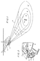
- Figure 1 is a perspective view of an airborne platform, such as a helicopter, having a search light mounted thereon, wherein the search light has an adjustable focus;
- Figure 2 is a perspective view of a portion of the airborne platform of Figure 1 showing a search light employing features of the present invention mounted thereon;
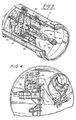
- Figure is a perspective view of a search light configured in accordance with the prior art showing a cam driven by a motor for adjusting the focus of the search light of Figures 1 and 2;
- Figure 4 is a perspective view of a back plate of the search light of Figure 3 modified to include circuitry configured in accordance with the present invention;
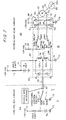
- Figure 5 is a circuit diagram illustrating a search light focus control circuit configured in accordance with the principles of the present invention, the circuit being in an inactive mode prior to applying electric power to the circuit;
- Figure 6 is the circuit of Figure 5 but showing the circuit energized by DC current applied thereto;
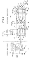
- Figure 7 is the circuit of Figures 5 and 6 but showing the circuit energized to rotate the armature of a focus control motor to drive a bidirectional cam in a clockwise direction, and
- Figure 8 is the circuit of Figures 5-7 but showing the circuit energized to rotate the armature of the focus control motor to drive the bidirectional cam in a counter-clockwise direction.
-
- Referring now to Figure 1, there is shown a platform in the form of a
helicopter 10 having afuselage 11 with asearch light 12 mounted thereon, the search light casting alight beam 14 with a focus angle , which light beam illuminates anarea 16 of ground or water. Frequently, it is desirable to expand or decrease thearea 16 being illuminated by expanding or contracting the focus angle of thebeam 14. For example, in order to search alarge area 16" for aparticular subject 18, thebeam 14 has a wide focus angle 1. In order to concentrate on aspecific subject 18, such as the person, thebeam 14 is progressively narrowed to have a focus angle of 2, illuminating a smaller area 16'. In accordance with the present invention, the focus angle is changeable bidirectionally by a control within thehelicopter 10 to either immediately widen the focus angle so as to approach 1 or to immediately narrow the focus angle so as to approach 2. - Referring now to Figure 2, it is seen that the
search light 12 is mounted on a gimble 20 which is in turn supported by atripod arrangement 22 attached to the fuselage I 1 of thehelicopter 10. The gimble 20 is driven byelectric drives beam 14 so that the beam can move independently of the orientation of thehelicopter 10. Thesearch light 12 also includes abulb 26 and an internal focus DC control motor 28 (see Figures 3 and 4). Thedrive 24,bulb 26 andfocus motor 28 each receive +28 volt DC power from thehelicopter 10 through an externalwire harness cable 30, whichwire harness cable 30 includes a single wire interface 32 (see Figures 5-8) for controlling theDC motor 28. - As is seen in Figure 2, the
wire harness 30 has aconnector 34 at one end thereof which plugs into acooperating connector 36 connected to internal cables (not shown) within thefuselage 11 of thehelicopter 10. The type ofsearch light 12 is exemplified commercially by search lights available from SpectroLab, Inc., of Sylmar, California, a Hughes Electronics Corporation company, and identified as NIGHTSUN® SX-16® and STARBURST SX-5® search lights. - Referring now mainly to Figures 3 and 4, where
interior portions 40 of thesearch light 12 are shown, it is seen that themotor 28 drives acam 42 asarmature 43 rotates. Thecam 42 abuts acam follower 44 which is urged bysprings 45 against the cam. Thecam follower 44 is connected byrods 46 to areflector 47 which, when moved axially in the direction ofarrow 48, narrows the focus angle toward the minimum focus angle 2 and which when moved in the direction of thearrow 49 widens the focus angle toward the maximum focus angle 1. - Referring now mainly to Figure 4, the housing of the
search light 12 has aback plate 52 on which has been mounted a circuit board 53, which in turn mounts the components of a searchlight head circuit 60. The search light head circuit is a switching circuit through which current passes to drive theDC motor 28 to rotate thearmature 43 in either a clockwise direction or the counter-clockwise direction. - According to the present invention, the
armature 43 of theDC motor 28 bidirectionally rotates thecam 42 in order to axially slidefocus control rods 46 and thus axially position thereflector 47. Thefocus control rods 46 and thecam 42 already exists in prior art search lights 12 if the search lights are exemplified by the NIGHTSUN SX-16® and STARBURST SX-5® search lights. In accordance with the prior art, theDC motor 28 rotates thecam 42 in only one direction. Consequently, there can be a lag period as thecam 42 cycles around to a desired focus angle that was passed in a previous focus angle adjustment. By utilizing the present invention, the lag time is eliminated because the rotation of thecam 42 is now bidirectional. - Having a
bidirectional cam 42 to allow an immediate change in the magnitude of the focus angle is of considerable interest to police departments. This is because the focus angle is only one of several activities performed by a police helicopter pilot during a search in that the pilot must also adjust thesearch light 12 while simultaneously flying thehelicopter 10 and talking on the radio. TV stations fly their own helicopters videoing the pursuit of criminal suspects. The pursuit is broadcast in real time by television stations as information for, and perhaps entertainment of, the general public. If a pursuit takes place at night, thesearch light beam 14 is of primary significance and is an important aspect in enhancing the spectacle. The police helicopter pilot then has the added pressure of thousands of excited television fans before whom he must perform. Having bidirectional focus angle control makes it less likely that pilot will mess up and lose sight of the suspect, a mistake not lot on his television audience. This enhancement of focus angle control is also of enormous value in other operations, such as, for example, attempting a rescue at sea during a storm, rescuing hikers stranded in the wilderness or medivacting the injured or sick. - Referring now to Figures 5-8, there is shown a diagram of circuitry according to the present invention which allows the search
light head circuit 60 disposed within thesearch light 12 to function as a switching circuit controlled from acontrol box circuit 62 situated within thefuselage 11 of thehelicopter 10 by utilizing only thesingle wire interface 32 currently within thewiring harness 30. The searchlight head circuit 60 includes adual relay 64 which is connected through aprotective diode pair 65 to thesingle wire interface 32 as well as adiode array 66 which protects themotor 28 from voltage spikes. - Within the
control box circuit 62 located in thehelicopter 10 there is a remotely positioned, bidirectional control switch SW1 that is connected to thedual relay 64 in the searchlight head circuit 60 by thesingle wire interface 32. Since the control switch SW1 is in the fuselage of thehelicopter 10, it is remotely positioned with respect to thesearch light 12 which is mounted exteriorly with respect to the fuselage in thetripod 22. The control switch SW1 is a manual switch having three positions. i.e., the OFF position shown in Figures 5 and 6 in which bothmomentary contacts momentary contact 70 is closed as is shown in Figure 7, and a second momentary closed position in which themomentary contact 71 is closed as is shown in Figure 8. As will be explained hereinafter, there is a change in state on the single wire interface depending on the position of the control switch SW1 so that in the first momentary closed position, theDC motor 28 rotates thefocus control cam 42 clockwise as is shown in Figure 7 and in the second momentary closed position of Figure 8, theDC motor 28 rotates thecam 42 in the counter-clockwise direction as is seen in Figure 8. - In a preferred embodiment of the invention, the
dual relay 64 is a double pole, single throw relay. As is seen in Figure 4, thedual relay 64 is conveniently mountable on circuit board 53 attached to theback plate 52 of the housing ofsearch light 12, which back plate already has space available to receive the circuit board 53, thus allowing unidirectional prior art focusing arrangements to be conveniently converted to bidirectional focusing arrangements. - Considering the circuit elements more specifically, the momentary
closed contact 70 is connected through a 100 ohm 3-watt resistor R1 to a power source provided by a +28 voltDC power supply 72 and through a first 18-volt Zener diode DZ1 to ground 73. Throughout these drawing figures the power source is the helicopter's +28 voltDC power supply 72 andground 73 is the helicopter grounding system. In other applications the power source may be different, for example, in a boat or motor vehicle the power source may be +12 volt DC. Thedual relay 64 has afirst coil 76 therein which is connected via aline 77 to the 28-volt DC power source via a 100 ohm 3-watt resistor R2 and which is connected to ground through a second 18-volt Zener diode DZ2. Asecond coil 78 is connected directly to ground via aline 79, while thefirst coil 76 andsecond coil 78 are mutually connected to thesingle wire interface 32 through protective diode pair comprising diodes D1 and D2. The protective diodes D1 and D2 are flyback diodes which clamp any voltage flybacks which occur when thecoils dual relay 64 are switches SW2 and SW3. Switches SW2 and SW3 close normally closedcontacts DC power supply 72 vialine 83 while normallyopen contacts line 88. Thecoils single wire interface 32 which as explained hereinafter reverses polarity of current flowing through themotor 28. - The
DC motor 28 is connected vialine 90 to the +28-voltDC power supply 72 through protective diode D3 while theline 91 is connected to the +28-volt power supply 72 through protective diode D4.Line 90 is also connected to ground through protective diode D5 whileline 91 is connected to ground 73 through protective diode D6. The diodes D3-D6 suppress both positive and negative voltage spikes that are generated when switching theDC motor 28 "on" and "off'. The Zener diodes DZ1 and DZ2 regulate the power supply voltage down from +28 volts DC to +18 volts DC for use by the manual control switch SW1 and by the components of thedual relay 64. - Considering now the operation of the circuitry of Figures 5-8, Figure 5 illustrates the condition of circuitry when the
helicopter 10 is not operating and thus not generating +28-volt DC power for thepower supply 72. Accordingly, in Figure 5 the +28-volt DC power is not shown. In this condition, switch SW1 in thecontrol box circuit 62 is in the OFF position and the switches SW2 and SW3 and thedual relay 64 are open.
Upon starting thehelicopter 10 so as to supply +28-volt DC power as illustrated in Figure 6, the switch SW1 remains open but the switches SW2 and SW3 automatically switch to a normally open mode in which they contact the normallyopen contacts line 90 andline 91 to ground 73 by energizing both thefirst coil 76 and thesecond coil 78. When switch SW1 is open, no voltage from thecontrol box 62 in thefuselage 11 of thehelicopter 10 is present on thesingle wire interface 32, consequently the voltage is allowed to float to a potential of about +9 volts due to the matched resistance of the first andsecond coils coil 76. By having +9 volts across thecoils open contacts DC motor 28 is thus grounded on both poles provided byterminals DC power supply 72 is applied to bothline 90 andline 91 bylines armature 43 of the DC motor and thus thebidirectional cam 42 are then positively held stationary with no rotation. - Referring now to Figure 7 in which
clockwise rotation 100 of thearmature 43 andcam 42 occurs, it is seen-that when the switch SW1 is moved to close with thecontact 70, there is a change in state on the single interface wire from an inactive state to a first active state where +18 volts is applied through thesingle interface wire 32, the resistor R1 having reduced the +28 voltDC power supply 72. Application of+18 volts to thesingle wire interface 32 to place the single wire interface in the first state causes thefirst coil 76 to de-energize while thesecond coil 78 remains energized. This causes the first relay switch SW2 to close with thecontact 81 while the second relay switch SW3 remains closed with the normallyopen contact 86. Current therefore flows through the first relay switch SW2,line 90 andDC motor 28 to ground 73 throughline 91 and the second relay switch SW3. This causes thearmature 43 of themotor 28 to rotate thebidirectional cam 42 in theclockwise direction 100 as long as the switch SW1 in thecontrol box circuit 62 closes with thecontact 70. Upon releasing the switch SW1, the first relay switch SW2 returns to the OFF position so that the first relay switch SW2 opens the normally closedcontact 81 and closes the normallyopen contact 84, thus returning the circuitry to the mode of Figure 6, which positively holds thearmature 43 and thus thecam 42 positively fixed with no rotation so as to stabilize the selected focus angle of thebeam 14. - Referring now to Figure 8 if it is desired that the
armature 43 and thecam 42 rotate in thecounter-clockwise direction 102, the manual switch SW1 is moved from the inactive off state to close withcontact 71 which puts thesingle interface wire 32 in a second active state. This causes thesecond coil 78 to de-energize while thefirst coil 76 remains energized which results in the second relay switch SW3 closing withcontact 82 while the first relay contact switch SW2 remains closed with the normallyopen contact 84. Power supplied +28-volt DC current flows through the second relay switch SW3 overline 91 and through themotor 28 toline 90.Line 90 is connected to ground 73 through the first relay switch SW2 so that in the mode of Figure 8, the direction of current flow to theDC motor 28 is reversed with respect to current flow through the DC motor in the mode shown in Figure 7. This causes thearmature 43 andcam 42 to rotate in thecounter-clockwise direction 102. When the manual control switch SW1 in thecontrol box circuit 62 is thereafter moved to the OFF position, the second relay switch SW3 opens contact with the normally closedcontact 82 and closes contact with the normallyopen contact 86 so that the circuit arrangement returns to the mode of Figure 6. As was stated before, when the circuit arrangement is in the stabilized mode of Figure 6, thearmature 43 is electrically locked to positively fix thebidirectional cam 42 in its last position so that the cam cannot inadvertently rotate and change the focus angle . - While the circuit disclosed in Figures 5-8 is a preferred circuit, corresponding circuits using equivalent components such as power transistors and chips which are now available or which may become available in the future are within the purview of this disclosure.
- In the aforedescribed exemplary embodiment of the invention, the following specific circuit components were used:
- Dual relay 64 - double pole, single-throw dual relay Model No. V2R-1002, available from Potter & Brumfield;
- DC Motor 28 - DC motor with a permanent magnet available from Globe Motors Co.;
- Zener diodes DZ1 and DZ2 - 1N5355B-18 volts;
- Diodes D1 - D6 - IN4936, and
- Resistors R1 and R2 - 100 ohm, 3-watt
-
- While the focus control described herein is especially useful for
search lights 12 mounted onhelicopters 10, it is also useful for mounting on fixed wing aircraft, boats, land vehicles, and stationary illuminating facilities. With applications other than helicopters and fixed-wing aircraft the power supply voltages may need to be altered so that the platform upon which the search light is mounted can readily accept the modification set forth in this disclosure. For example, boats and land vehicles may have a 12-voltDC power supply 72 so that the components of the circuits as shown in Figures 5-8 would need to be modified to operate from a 12-volt DC power supply rather than a 28 volt DC power supply. - From the foregoing description, one skilled in the art can easily ascertain the essential characteristics of this invention and, without departing from the scope of the present invention as defined in the appended claims, can make various changes and modifications of the invention to adapt it to var ous usages and conditions.
Claims (7)
- A focus control for narrowing and widening the focus angle of a search light beam (14) emitted by a search light (12) mounted on a platform (10) having a power source (72), wherein the search light (12) includes an electric motor (28), a cam (42) driveable by the motor (28) to rotate and a focus control (44, 45, 46, 47) operated by the cam (42) for narrowing and widening the focus angle in response to control signals over a single wire interface (32) between a remotely positioned control switch (SW1) and the motor (28), the focus control being characterized byan open position, a power source position and a ground position selectively assumable by the remotely positioned control switch (SW1), wherein when the remotely positioned control switch (SW1) is in the power source position, the single wire interface (32) is in a first state different from a second state of the single wire interface (32) which occurs when the remotely positioned control switch (SW1) is in the ground position, anda switching circuit (60) connected between the power source (72) and the motor (28) for reversing polarity of current flowing through the motor (28), the switching circuit (60) being connected to the remotely positioned control switch (SW1) by the single wire interface (32) and including an input (76, 78) responsive to a change in state on the single wire interface (32) to reverse the polarity of current flowing through the motor (28) to reverse rotational direction of the motor (28), whereby when the cam (42) reverses rotational direction thereby reversing the widening or narrowing of the focus angle .
- The focus control of claim 1, characterized in that the motor (28) is a DC motor and wherein circuitry is included for connecting both poles (92, 93) of the DC motor (28) to ground (73) when the remotely positioned switch (SW1) is in the open position and the power source (72) is energized.
- The focus control of claim 1 or 2, characterized in that diodes (D3-D6) are disposed between the first and second poles (92, 93) of the DC motor (28) and the DC power source (72) and between the poles (92, 93) and ground (73).
- The focus control of any of claims 1 to 3, characterized in that the input comprises a pair of coils (76, 78), one (76) connected to the power source (72); the other (78) connected to ground (73), and both (76 and 78) directly connected to the single wire interface (32) whereby a change in state of the single wire interface (32) deenergizes one coil (76 or 78) while the other remains energized, the coils (76 and 78) each being associated with a bipolar switch (SW2 or SW3) connected to the DC motor (28) and the coils (76, 78) being disposed between ground (73) and the power source (72), the bipolar switches (SW2 or SW3) individually changing connections to reverse polarity of current flowing through the DC motor (28) as coils (76, 78) are individually deenergized due to changes in state of the single wire interface (32).
- The focus control of claim 4, characterized in that protective diodes (D1, D2) are disposed between the DC power source (72) and the coils (76, 78) and the single wire interface (32) as well as between ground (73) and the single wire interface (32) to protect the coils (76, 78).
- The focus control of any of claims 1 to 5, characterized in that the switching circuit (62) comprises a double pole, single-throw dual relay (64).
- The focus control of any of claims 1 to 6, characterized in that the platform (10) is a helicopter (10) or fixed wing aircraft (10) having a fuselage (11); wherein the search light (12) is mounted on the helicopter (10) or aircraft (10) at a location exterior to the fuselage (11) and the remotely positioned switch (SW1) is disposed within the fuselage (11) and connected to the switching circuit (60) by the single wire interface (32).
Applications Claiming Priority (2)
| Application Number | Priority Date | Filing Date | Title |
|---|---|---|---|
| US500753 | 2000-02-08 | ||
| US09/500,753 US6191547B1 (en) | 2000-02-08 | 2000-02-08 | Focus control for search lights |
Publications (3)
| Publication Number | Publication Date |
|---|---|
| EP1124090A2 EP1124090A2 (en) | 2001-08-16 |
| EP1124090A3 EP1124090A3 (en) | 2003-08-20 |
| EP1124090B1 true EP1124090B1 (en) | 2005-07-27 |
Family
ID=23990768
Family Applications (1)
| Application Number | Title | Priority Date | Filing Date |
|---|---|---|---|
| EP01102086A Expired - Lifetime EP1124090B1 (en) | 2000-02-08 | 2001-01-31 | Focus control for search lights |
Country Status (10)
| Country | Link |
|---|---|
| US (1) | US6191547B1 (en) |
| EP (1) | EP1124090B1 (en) |
| JP (1) | JP2001266603A (en) |
| CN (1) | CN1135315C (en) |
| AU (1) | AU780600B2 (en) |
| BR (1) | BR0100382A (en) |
| CA (1) | CA2329962C (en) |
| DE (1) | DE60112141T2 (en) |
| IL (1) | IL141275A (en) |
| TW (1) | TW506186B (en) |
Families Citing this family (19)
| Publication number | Priority date | Publication date | Assignee | Title |
|---|---|---|---|---|
| US7080928B2 (en) * | 2001-12-12 | 2006-07-25 | Honeywell International Inc. | Electronically controlled aircraft retractable landing light with manual retraction capability |
| CA2543788C (en) * | 2003-10-23 | 2012-01-17 | Tsx Products Corporation | An apparatus for automatically pointing a device at a target |
| US7277265B2 (en) * | 2004-06-22 | 2007-10-02 | General Motors Corporation | Robust power take-off and cruise enable |
| ITTV20070014A1 (en) * | 2007-02-05 | 2008-08-06 | Nice Spa | MOTOR UNIT FOR DRIVE FOR GATES |
| JP5047843B2 (en) * | 2008-03-06 | 2012-10-10 | 株式会社小糸製作所 | Aircraft exterior lighting |
| US8004810B2 (en) * | 2008-06-18 | 2011-08-23 | Elster Electricity, Llc | Meter having load control unit |
| US8297811B2 (en) * | 2008-07-28 | 2012-10-30 | Koito Manufacturing Co., Ltd. | Aircraft lamp |
| WO2010030566A1 (en) | 2008-09-11 | 2010-03-18 | Itt Manufacturing Enterprises, Inc. | Searchlight having rotational beam focus for marine applications |
| CN101839450B (en) * | 2010-01-13 | 2013-10-09 | 海洋王照明科技股份有限公司 | Focusing device of lamp fitting and variable-focus illumination lamp fitting thereof |
| EP2625360A1 (en) * | 2010-10-04 | 2013-08-14 | Dr. Hahn GmbH & Co. KG | Method and device for contactless transmission of electric energy and/or electric signals between a wall and a wing fastened to said wall |
| US8996203B2 (en) * | 2012-04-02 | 2015-03-31 | The Boeing Company | Searchlight location system |
| EP3095710B1 (en) * | 2015-05-20 | 2018-01-03 | Goodrich Lighting Systems GmbH | Dynamic exterior aircraft light unit and method of operating a dynamic exterior aircraft light unit |
| EP3447372A1 (en) * | 2017-08-24 | 2019-02-27 | Goodrich Lighting Systems GmbH | Helicopter search light and method of operating a helicopter search light |
| US10377299B2 (en) * | 2017-09-11 | 2019-08-13 | Ford Global Technologies, Llc | Vehicle spotlight with tracking feature |
| US10562440B1 (en) | 2019-02-04 | 2020-02-18 | Danial Julian | Directional lighting system |
| US11192494B2 (en) | 2020-02-07 | 2021-12-07 | Honeywell International Inc. | Systems and methods for search and landing light |
| CN111673269B (en) * | 2020-07-01 | 2022-05-31 | 中国工程物理研究院激光聚变研究中心 | Focal spot rapid movement regulation and control system based on surface type reflector set and regulation and control method thereof |
| WO2022192698A1 (en) | 2021-03-12 | 2022-09-15 | Essex Industries, Inc., | Rocker switch |
| EP4309200A1 (en) | 2021-03-15 | 2024-01-24 | Essex Industries, Inc. | Five-position switch |
Family Cites Families (12)
| Publication number | Priority date | Publication date | Assignee | Title |
|---|---|---|---|---|
| DE1806312C3 (en) * | 1968-10-31 | 1980-11-20 | Robert Bosch Gmbh, 7000 Stuttgart | Headlamp leveler for vehicle headlights |
| US3979649A (en) * | 1974-08-09 | 1976-09-07 | Persha Gerald C | Remote searchlight control system |
| US3987296A (en) * | 1975-01-17 | 1976-10-19 | Danforth, Div. Of Eastern Co. | Searchlight |
| US4353110A (en) * | 1980-09-12 | 1982-10-05 | Ellis Richard D | Search and warning light system |
| US4729077A (en) * | 1986-03-10 | 1988-03-01 | Mycro Group Co. | Variable beam width lighting device |
| US5228770A (en) * | 1989-05-12 | 1993-07-20 | Brunson Robert L | Search light |
| US5030886A (en) * | 1990-05-25 | 1991-07-09 | Union Switch & Signal Inc. | Self-checking circuit arrangement for operation of a searchlight signal |
| US5490046A (en) * | 1994-02-23 | 1996-02-06 | Gohl; Gerald L. | Portable, remote-controlled searchlight apparatus |
| US5673989A (en) * | 1994-02-23 | 1997-10-07 | Gohl; Gerald Lee | Wireless, remote-controlled portable searchlight |
| US5695272A (en) * | 1994-05-27 | 1997-12-09 | Grimes Aerospace Company | Search light for aircraft and other vehicles |
| US5589901A (en) * | 1995-05-15 | 1996-12-31 | Means; Kevin P. | Apparatus and method for synchronizing search and surveillance devices |
| US5806956A (en) * | 1996-09-18 | 1998-09-15 | Hyun-Jo; Lee | Searchlight |
-
2000
- 2000-02-08 US US09/500,753 patent/US6191547B1/en not_active Expired - Lifetime
- 2000-12-29 CA CA002329962A patent/CA2329962C/en not_active Expired - Lifetime
-
2001
- 2001-01-31 EP EP01102086A patent/EP1124090B1/en not_active Expired - Lifetime
- 2001-01-31 DE DE60112141T patent/DE60112141T2/en not_active Expired - Lifetime
- 2001-02-05 IL IL14127501A patent/IL141275A/en not_active IP Right Cessation
- 2001-02-07 TW TW090102629A patent/TW506186B/en not_active IP Right Cessation
- 2001-02-07 BR BR0100382-8A patent/BR0100382A/en not_active IP Right Cessation
- 2001-02-07 AU AU18340/01A patent/AU780600B2/en not_active Expired
- 2001-02-08 CN CNB011024984A patent/CN1135315C/en not_active Expired - Lifetime
- 2001-02-08 JP JP2001032455A patent/JP2001266603A/en active Pending
Also Published As
| Publication number | Publication date |
|---|---|
| BR0100382A (en) | 2002-07-23 |
| AU1834001A (en) | 2001-08-09 |
| DE60112141T2 (en) | 2006-06-01 |
| EP1124090A3 (en) | 2003-08-20 |
| EP1124090A2 (en) | 2001-08-16 |
| CA2329962A1 (en) | 2001-08-08 |
| JP2001266603A (en) | 2001-09-28 |
| AU780600B2 (en) | 2005-04-07 |
| DE60112141D1 (en) | 2005-09-01 |
| CA2329962C (en) | 2005-03-29 |
| IL141275A0 (en) | 2002-03-10 |
| CN1350138A (en) | 2002-05-22 |
| IL141275A (en) | 2004-02-19 |
| CN1135315C (en) | 2004-01-21 |
| TW506186B (en) | 2002-10-11 |
| US6191547B1 (en) | 2001-02-20 |
Similar Documents
| Publication | Publication Date | Title |
|---|---|---|
| EP1124090B1 (en) | Focus control for search lights | |
| EP1441952B1 (en) | Multi-mode searchlight | |
| AU2002363327A1 (en) | Multi-mode searchlight | |
| US5589901A (en) | Apparatus and method for synchronizing search and surveillance devices | |
| US8325232B2 (en) | Wireless camera surveillance system for an aircraft | |
| US4981363A (en) | Emergency light/spotlight mechanism for automotive vehicles | |
| US6315435B1 (en) | Electronically controlled searchlight having multiple preset positions | |
| US20120176526A1 (en) | Camera light | |
| US5355131A (en) | Aircraft landing light | |
| US5793164A (en) | Low intensity aircraft rotor tip illumination | |
| EP1683720B1 (en) | Multi-mode searchlight | |
| US5499167A (en) | Spotlight unit for use on a vehicle | |
| EP3657912B1 (en) | Controllable micro light emitting diode system and method | |
| KR101895502B1 (en) | An assembly comprising a movable and brakable/dampable part and a method for braking a movable part | |
| AU2006201435A1 (en) | Multi-mode searchlight | |
| US6414456B1 (en) | Positioning device | |
| US2475066A (en) | Follow-up electric motor control apparatus | |
| KR20170012985A (en) | Integrated lantern control system | |
| KR200400915Y1 (en) | Automatic visual field viewer for cars | |
| GB2205968A (en) | Remote viewing optical fibre cable systems |
Legal Events
| Date | Code | Title | Description |
|---|---|---|---|
| PUAI | Public reference made under article 153(3) epc to a published international application that has entered the european phase |
Free format text: ORIGINAL CODE: 0009012 |
|
| AK | Designated contracting states |
Kind code of ref document: A2 Designated state(s): AT BE CH CY DE DK ES FI FR GB GR IE IT LI LU MC NL PT SE TR |
|
| AX | Request for extension of the european patent |
Free format text: AL;LT;LV;MK;RO;SI |
|
| PUAL | Search report despatched |
Free format text: ORIGINAL CODE: 0009013 |
|
| AK | Designated contracting states |
Designated state(s): AT BE CH CY DE DK ES FI FR GB GR IE IT LI LU MC NL PT SE TR |
|
| AX | Request for extension of the european patent |
Extension state: AL LT LV MK RO SI |
|
| RIC1 | Information provided on ipc code assigned before grant |
Ipc: 7F 21V 19/02 A Ipc: 7B 60Q 1/24 B Ipc: 7F 21W 101:06 Z |
|
| 17P | Request for examination filed |
Effective date: 20040211 |
|
| AKX | Designation fees paid |
Designated state(s): DE FR GB GR IT |
|
| GRAP | Despatch of communication of intention to grant a patent |
Free format text: ORIGINAL CODE: EPIDOSNIGR1 |
|
| GRAS | Grant fee paid |
Free format text: ORIGINAL CODE: EPIDOSNIGR3 |
|
| GRAA | (expected) grant |
Free format text: ORIGINAL CODE: 0009210 |
|
| AK | Designated contracting states |
Kind code of ref document: B1 Designated state(s): DE FR GB GR IT |
|
| REG | Reference to a national code |
Ref country code: GB Ref legal event code: FG4D |
|
| REF | Corresponds to: |
Ref document number: 60112141 Country of ref document: DE Date of ref document: 20050901 Kind code of ref document: P |
|
| REG | Reference to a national code |
Ref country code: GR Ref legal event code: EP Ref document number: 20050403117 Country of ref document: GR |
|
| ET | Fr: translation filed | ||
| PLBE | No opposition filed within time limit |
Free format text: ORIGINAL CODE: 0009261 |
|
| STAA | Information on the status of an ep patent application or granted ep patent |
Free format text: STATUS: NO OPPOSITION FILED WITHIN TIME LIMIT |
|
| 26N | No opposition filed |
Effective date: 20060428 |
|
| PGFP | Annual fee paid to national office [announced via postgrant information from national office to epo] |
Ref country code: GR Payment date: 20070129 Year of fee payment: 7 |
|
| PG25 | Lapsed in a contracting state [announced via postgrant information from national office to epo] |
Ref country code: GR Free format text: LAPSE BECAUSE OF NON-PAYMENT OF DUE FEES Effective date: 20080804 |
|
| REG | Reference to a national code |
Ref country code: FR Ref legal event code: PLFP Year of fee payment: 16 |
|
| REG | Reference to a national code |
Ref country code: FR Ref legal event code: PLFP Year of fee payment: 17 |
|
| REG | Reference to a national code |
Ref country code: FR Ref legal event code: PLFP Year of fee payment: 18 |
|
| PGFP | Annual fee paid to national office [announced via postgrant information from national office to epo] |
Ref country code: GB Payment date: 20200127 Year of fee payment: 20 Ref country code: IT Payment date: 20200123 Year of fee payment: 20 Ref country code: DE Payment date: 20200129 Year of fee payment: 20 |
|
| PGFP | Annual fee paid to national office [announced via postgrant information from national office to epo] |
Ref country code: FR Payment date: 20200127 Year of fee payment: 20 |
|
| REG | Reference to a national code |
Ref country code: DE Ref legal event code: R071 Ref document number: 60112141 Country of ref document: DE |
|
| REG | Reference to a national code |
Ref country code: GB Ref legal event code: PE20 Expiry date: 20210130 |
|
| PG25 | Lapsed in a contracting state [announced via postgrant information from national office to epo] |
Ref country code: GB Free format text: LAPSE BECAUSE OF EXPIRATION OF PROTECTION Effective date: 20210130 |