EP1110792A2 - Method and system for continued vehicle control in an adaptive speed control system at vehicle speeds below a minimum operating speed when a sensed target disappears - Google Patents
Method and system for continued vehicle control in an adaptive speed control system at vehicle speeds below a minimum operating speed when a sensed target disappears Download PDFInfo
- Publication number
- EP1110792A2 EP1110792A2 EP00311067A EP00311067A EP1110792A2 EP 1110792 A2 EP1110792 A2 EP 1110792A2 EP 00311067 A EP00311067 A EP 00311067A EP 00311067 A EP00311067 A EP 00311067A EP 1110792 A2 EP1110792 A2 EP 1110792A2
- Authority
- EP
- European Patent Office
- Prior art keywords
- vehicle
- target
- range
- sensed target
- speed
- Prior art date
- Legal status (The legal status is an assumption and is not a legal conclusion. Google has not performed a legal analysis and makes no representation as to the accuracy of the status listed.)
- Granted
Links
Images

Classifications
-
- B—PERFORMING OPERATIONS; TRANSPORTING
- B60—VEHICLES IN GENERAL
- B60W—CONJOINT CONTROL OF VEHICLE SUB-UNITS OF DIFFERENT TYPE OR DIFFERENT FUNCTION; CONTROL SYSTEMS SPECIALLY ADAPTED FOR HYBRID VEHICLES; ROAD VEHICLE DRIVE CONTROL SYSTEMS FOR PURPOSES NOT RELATED TO THE CONTROL OF A PARTICULAR SUB-UNIT
- B60W30/00—Purposes of road vehicle drive control systems not related to the control of a particular sub-unit, e.g. of systems using conjoint control of vehicle sub-units, or advanced driver assistance systems for ensuring comfort, stability and safety or drive control systems for propelling or retarding the vehicle
- B60W30/14—Adaptive cruise control
- B60W30/16—Control of distance between vehicles, e.g. keeping a distance to preceding vehicle
-
- B—PERFORMING OPERATIONS; TRANSPORTING
- B60—VEHICLES IN GENERAL
- B60K—ARRANGEMENT OR MOUNTING OF PROPULSION UNITS OR OF TRANSMISSIONS IN VEHICLES; ARRANGEMENT OR MOUNTING OF PLURAL DIVERSE PRIME-MOVERS IN VEHICLES; AUXILIARY DRIVES FOR VEHICLES; INSTRUMENTATION OR DASHBOARDS FOR VEHICLES; ARRANGEMENTS IN CONNECTION WITH COOLING, AIR INTAKE, GAS EXHAUST OR FUEL SUPPLY OF PROPULSION UNITS IN VEHICLES
- B60K31/00—Vehicle fittings, acting on a single sub-unit only, for automatically controlling vehicle speed, i.e. preventing speed from exceeding an arbitrarily established velocity or maintaining speed at a particular velocity, as selected by the vehicle operator
- B60K31/0008—Vehicle fittings, acting on a single sub-unit only, for automatically controlling vehicle speed, i.e. preventing speed from exceeding an arbitrarily established velocity or maintaining speed at a particular velocity, as selected by the vehicle operator including means for detecting potential obstacles in vehicle path
-
- B—PERFORMING OPERATIONS; TRANSPORTING
- B60—VEHICLES IN GENERAL
- B60T—VEHICLE BRAKE CONTROL SYSTEMS OR PARTS THEREOF; BRAKE CONTROL SYSTEMS OR PARTS THEREOF, IN GENERAL; ARRANGEMENT OF BRAKING ELEMENTS ON VEHICLES IN GENERAL; PORTABLE DEVICES FOR PREVENTING UNWANTED MOVEMENT OF VEHICLES; VEHICLE MODIFICATIONS TO FACILITATE COOLING OF BRAKES
- B60T7/00—Brake-action initiating means
- B60T7/12—Brake-action initiating means for automatic initiation; for initiation not subject to will of driver or passenger
- B60T7/22—Brake-action initiating means for automatic initiation; for initiation not subject to will of driver or passenger initiated by contact of vehicle, e.g. bumper, with an external object, e.g. another vehicle, or by means of contactless obstacle detectors mounted on the vehicle
-
- B—PERFORMING OPERATIONS; TRANSPORTING
- B60—VEHICLES IN GENERAL
- B60W—CONJOINT CONTROL OF VEHICLE SUB-UNITS OF DIFFERENT TYPE OR DIFFERENT FUNCTION; CONTROL SYSTEMS SPECIALLY ADAPTED FOR HYBRID VEHICLES; ROAD VEHICLE DRIVE CONTROL SYSTEMS FOR PURPOSES NOT RELATED TO THE CONTROL OF A PARTICULAR SUB-UNIT
- B60W2520/00—Input parameters relating to overall vehicle dynamics
- B60W2520/10—Longitudinal speed
Definitions
- This invention relates to a method and system for continued vehicle control in an adaptive speed control system at a vehicle speed below a minimum operating speed threshold when a sensed target disappears, based on a phantom target generated to compensate for the loss of the sensed target.
- Adaptive Cruise (i.e ., speed) Control (ACC) systems operate much like conventional Cruise Control systems, with the added capability of being able to sense in-path vehicles and to slow the ACC equipped vehicle in response.
- An ACC equipped vehicle thereby allows its operator to automatically control the vehicle speed, as with conventional Cruise Control, without the necessity of having to deactivate and reactivate control whenever slower traffic is encountered.
- ACC methods and systems use a forward looking range sensor such as radar to sense an in-path vehicle (which may also be referred to as a sensed target or primary target). Based on the radar sensor information, such ACC methods and systems then determine the range and relative velocity (or range rate) of the sensed in-path vehicle. Using the range and range rate, the speed of the ACC equipped vehicle is controlled to maintain a selected following interval between the ACC equipped vehicle and the sensed in-path vehicle. The speed of the ACC equipped vehicle is typically controlled by automatic control of the vehicle throttle actuator. In more advanced ACC methods and systems, vehicle speed may also be controlled by automatic control of vehicle brake actuators. Such ACC methods and systems have the ability to apply a moderate degree of braking to the vehicle to achieve further vehicle deceleration (i.e. , in addition to vehicle deceleration achieved via throttle control) in response to an in-path vehicle.
- ACC systems may decelerate the ACC equipped vehicle to a speed less than a minimum operating speed threshold.
- the ACC system is simply deactivated. This is typically accomplished by "fading" the vehicle brakes. That is, the vehicle brake actuators are controlled to gradually decrease to zero the hydraulic pressure applied to the vehicle brakes. Thereafter, the ACC system having been deactivated, absent intervention by the vehicle operator, the vehicle simply coasts.
- such a method and system would compensate for the loss of the sensed target by controlling the speed of the ACC equipped vehicle based on the range and range rate of a phantom target.
- a phantom target would be created from the last known range and range rate of the sensed target that has disappeared from the radar tracking files of the ACC system.
- Below the minimum operating speed threshold such a method and system could thereby allow, for example, the ACC equipped vehicle to maintain braking even if the in-path sensed vehicle has disappeared. In so doing, such a method and system would provide the ACC equipped vehicle with a smoother, more comfortable response.
- a method and system for continued vehicle control at a vehicle speed below a minimum operating speed threshold when a sensed target disappears.
- the method comprises determining whether the vehicle speed is less than the minimum operation speed threshold, determining whether a sensed target has disappeared if the vehicle speed is less than the minimum operating speed, and generating a phantom target having a range and range rate corresponding to a last known range and range rate, respectively, of the sensed target if the sensed target has disappeared.
- the method further comprises controlling the vehicle speed based on the range and range rate of the phantom target.
- the system of the present invention includes a receiver capable of receiving an input signal indicative of the vehicle speed, and a controller capable of determining whether the vehicle speed is less than the minimum operating speed threshold, capable of determining whether a sensed target has disappeared if the vehicle speed is less than the minimum operating speed threshold, and capable of generating a phantom target having a range and range rate corresponding to a last known range and range rate, respectively, of the sensed target if the sensed target has disappeared.
- the controller of the system of the present invention is further capable of controlling the vehicle speed based on the range and range rate of the phantom target.
- Figure 1 illustrates a simplified block diagram of an Adaptive Cruise Control (ACC) system, including the system of the present invention, denoted generally by reference numeral 10.
- ACC Adaptive Cruise Control
- ACC system 10 is a closed loop control system intended to respond to potential targets in front of and in the same lane of traffic as the vehicle equipped with the ACC system 10.
- the goal of ACC system 10 is to partially automate the continuous longitudinal control of the vehicle, thereby providing the vehicle operator with improved comfort and convenience.
- ACC system 10 may operate in either a normal or a following mode. In normal mode operation, ACC system 10 controls the speed of the ACC equipped vehicle to the speed set by the vehicle operator as the control speed. In following mode operation, ACC system 10 controls the speed of the ACC equipped vehicle to the speed of a sensed in-path vehicle (which may be referred to as a sensed target or a primary target).
- the ACC system 10 includes a vehicle controller 12 provided in communication with a range sensor 14, a speed sensor 16, a yaw rate sensor 18, a user interface 20, a throttle actuator 22, and a brake actuator 24.
- vehicle controller 12 uses throttle and brake actuators 22, 24 to control the speed of the ACC equipped vehicle in order to maintain a selected following interval (in seconds) between the ACC equipped vehicle and a sensed target in the forward path of travel of the ACC equipped vehicle (i.e. , a lead vehicle).
- the following interval between the ACC equipped vehicle and the sensed target is initially set at a default value (typically two seconds) upon activation of the system 10, but may be modified by the vehicle operator to any of a number of other selectable values via user interface 20.
- the default following interval is typically the maximum following interval allowed, and modification of the following interval by the vehicle operator is permitted between that maximum and a defined minimum following interval.
- the following interval is referred to as headway, and is defined as the range to the sensed target (in meters), divided by the speed of the ACC equipped vehicle (in meters per second).
- User interface 20 is also used by the vehicle operator to set the desired vehicle control speed.
- ACC systems and methods are well known in the art.
- a detailed description of the general operation of ACC system 10 including such functions as acquisition, discrimination, differentiation, selection and tracking of targets, range and relative velocity (range rate) determinations, sensor operations, and throttle and brake control is unnecessary and, for the sake of brevity, is not set forth herein.
- functions of ACC system 10 may be undertaken in any fashion known to those of ordinary skill.
- existing ACC methods and systems may decelerate the ACC equipped to a speed less than a minimum operating speed threshold.
- the ACC system is simply deactivated. This is typically accomplished by "fading" the vehicle brakes. That is, the vehicle brake actuators are controlled to gradually decrease to zero the hydraulic pressure applied to the vehicle brakes. Thereafter, the ACC system having been deactivated, absent intervention by the vehicle operator, the vehicle simply coasts.
- the present invention provides, in an ACC system, a method and system for continued control of an ACC equipped vehicle when the speed of the vehicle decreases below the minimum operating speed threshold and the sensed target disappears.
- the present invention adds to an ACC equipped vehicle the ability to control the vehicle speed based on a phantom target. More specifically, when maintaining the selected following interval, if the speed of the ACC equipped vehicle decreases below the minimum operating speed threshold, the present invention determines whether the sensed in-path target vehicle has disappeared (such as where the sensed target leaves the path of the ACC equipped vehicle, the ACC equipped vehicle leaves the path of the sensed target, or the sensed target reaches a sufficiently low speed that it can no longer be identified).
- the present invention compensates for the loss of the sensed target by controlling the speed of the ACC equipped vehicle based on the range and range rate of a phantom target.
- the phantom target is created from the last known range and rage rate of the sensed target that has disappeared from the radar tracking files of the ACC system.
- the present invention could allow, for example, the ACC equipped vehicle to maintain braking even if the in-path sensed vehicle has disappeared. In so doing, the present invention provides the ACC equipped vehicle with a smoother, more comfortable response.
- ACC equipped vehicle 30 uses radar pattern 32 of an ACC range sensor (not shown) to identify lead vehicle 34 as a sensed target. If necessary, ACC equipped vehicle 30 automatically decelerates to maintain a selected headway setting. Such deceleration may result in the speed of ACC equipped vehicle 30 decreasing below a minimum operating threshold speed. As previously noted, in that event, the ACC system is simply deactivated, which is typically accomplished by "fading" the vehicle brakes. That is, the vehicle brake actuators are controlled to gradually decrease to zero the hydraulic pressure applied to the vehicle brakes.
- the present invention provides, in the ACC system 10 of Figure 1, a method and system for continued braking of the ACC equipped vehicle when the vehicle speed falls below the minimum operation speed and the sensed target disappears. More specifically, in the event the vehicle speed is less than the minimum operating speed, the method and system first determine whether the sensed target has disappeared. In that regard, referring to Figure 2b, it can be seen that lead vehicle 34 has changed lanes, thereby disappearing from radar pattern 32 of ACC equipped vehicle 30. A sensed target may also disappear when, for example, lead vehicle 34 continues in its present lane and ACC equipped vehicle 30 changes lanes (not shown). Still further, a sensed target may also disappear if it reaches a sufficiently low speed that it can no longer be identified.
- the method and system of the present invention compensate for such a disappearance by generating a phantom target having its own range and range rate values.
- the initial values of the range and range rate of the phantom target correspond to the last known range and range rate, respectively, of the lost sensed target. Subsequent values of the range and range rate of the phantom target are extrapolated.
- the method and system of the present invention then control the speed of the ACC equipped vehicle based on the range and range rate of the phantom target.
- One type of such control may include continued braking of the ACC equipped vehicle to reduce vehicle speed, including possibly stopping the vehicle.
- the method and system While the method and system control the speed of the ACC equipped vehicle based on the phantom target, the method and system also continue to determine whether a sensed target has been reacquired. If a sensed target is not reacquired, the method and system continue to control the speed of the ACC equipped vehicle based on the phantom target. If, however, a sensed target is reacquired, the method and system of the present invention may then permit operation of the following mode of the ACC system 10 to resume, based on the target information (including range and range rate) of the newly acquired primary target. Such a resumption of following mode operation may include deactivation of the ACC system 10, particularly where the speed of the ACC equipped vehicle is less than the minimum operating speed.
- such deactivation would preferably include "fading" the vehicle brakes ( i.e., gradually reducing to zero the amount of hydraulic pressure applied to the vehicle brakes).
- an improved response of the ACC equipped vehicle is provided. By allowing, for example, the ACC equipped vehicle to continue braking even though the sensed target has disappeared, the present invention provides the ACC equipped vehicle with a smoother, more comfortable response.
- vehicle controller 12 includes a receiver (not shown) capable of receiving an input signal from speed sensor 16 indicative of the speed of the ACC equipped vehicle.
- Vehicle controller 12 also includes a controller (not shown) a controller capable of determining whether the vehicle speed is less than the minimum operating speed threshold, determining whether a sensed target has disappeared if the vehicle speed is less than the minimum operating speed threshold, generating a phantom target having a range and range rate corresponding to a last known range and range rate, respectively, of the sensed target if the sensed target has disappeared, and controlling the vehicle speed based on the range and range rate of the phantom target.
- the controller may be capable of reducing the vehicle speed by generating a brake control signal operative to control a brake actuator, including reducing the vehicle speed to zero.
- the controller of the system of the present invention may further capable of determining whether another sensed target has been acquired, and de-activating the adaptive speed control system if another sensed target has been acquired.
- the controller may be capable of generating a braking control signal operative to control a brake actuator to gradually reduce to zero an amount of hydraulic pressure applied by the brake actuator.
- the controller of the present invention (as well as vehicle controller 12 of ACC system 10) may take the form of an appropriately programmed microprocessor, or any equivalent thereof.
- existing ACC methods include a headway maintenance algorithm which operates based on existing target information 42, including the range and range rate of the primary target and a selected headway value.
- a headway maintenance algorithm which operates based on existing target information 42, including the range and range rate of the primary target and a selected headway value.
- Such an algorithm has been previously described as following mode operation and, once again, is well known to those of ordinary skill in the art.
- the ACC system may be deactivated, such as by "fading" the vehicle brakes to gradually decrease the braking force applied to the vehicle.
- the method of the present invention creates a phantom target based on the last known range and range rate of the lost sensed target 48, as described in detail above. Thereafter, according to the method of the present invention, the speed of the ACC equipped vehicle is controlled based on the phantom target, including the range and range rate of that phantom target 50, again as previously described in detail. In that regard, such control may include continued braking of the ACC equipped vehicle to reduce vehicle speed, including up to stopping the vehicle.
- a primary target has been reacquired 52. If not, control of the ACC equipped vehicle speed continues based on the phantom target, including the range and range rate of that phantom target 50. In the event, however, that a primary target has been reacquired, then operation of the headway maintenance algorithm resumes 42, based on the target information of the newly acquired primary target.
- the ACC system may be deactivated, such as by "fading" the vehicle brakes to gradually decrease the braking force applied to the vehicle.
- the present invention provides, in an adaptive speed control system for a vehicle, a method and system for continued vehicle control at vehicle speeds below a minimum operating speed threshold when a sensed target disappears.
- a method and system add to an ACC equipped vehicle the ability to control the vehicle speed based on the range and range rate of a phantom target created from the last known range and rage rate of the sensed target that has disappeared from the radar tracking files of the ACC system.
- Below the minimum operating speed threshold such a method and system may allow, for example, the ACC equipped vehicle to maintain braking even if the in-path sensed vehicle has disappeared. In so doing, such a method and system provide the ACC equipped vehicle with a smoother, more comfortable response.
Abstract
Description
- This invention relates to a method and system for continued vehicle control in an adaptive speed control system at a vehicle speed below a minimum operating speed threshold when a sensed target disappears, based on a phantom target generated to compensate for the loss of the sensed target.
- Adaptive Cruise (i.e., speed) Control (ACC) systems operate much like conventional Cruise Control systems, with the added capability of being able to sense in-path vehicles and to slow the ACC equipped vehicle in response. An ACC equipped vehicle thereby allows its operator to automatically control the vehicle speed, as with conventional Cruise Control, without the necessity of having to deactivate and reactivate control whenever slower traffic is encountered.
- As is well known in the art, existing ACC methods and systems use a forward looking range sensor such as radar to sense an in-path vehicle (which may also be referred to as a sensed target or primary target). Based on the radar sensor information, such ACC methods and systems then determine the range and relative velocity (or range rate) of the sensed in-path vehicle. Using the range and range rate, the speed of the ACC equipped vehicle is controlled to maintain a selected following interval between the ACC equipped vehicle and the sensed in-path vehicle. The speed of the ACC equipped vehicle is typically controlled by automatic control of the vehicle throttle actuator. In more advanced ACC methods and systems, vehicle speed may also be controlled by automatic control of vehicle brake actuators. Such ACC methods and systems have the ability to apply a moderate degree of braking to the vehicle to achieve further vehicle deceleration (i.e., in addition to vehicle deceleration achieved via throttle control) in response to an in-path vehicle.
- When maintaining the selected following interval, however, existing ACC methods and systems may decelerate the ACC equipped vehicle to a speed less than a minimum operating speed threshold. In such situations, the ACC system is simply deactivated. This is typically accomplished by "fading" the vehicle brakes. That is, the vehicle brake actuators are controlled to gradually decrease to zero the hydraulic pressure applied to the vehicle brakes. Thereafter, the ACC system having been deactivated, absent intervention by the vehicle operator, the vehicle simply coasts.
- Thus, in an ACC system, there exists a need for a method and system for continued control of an ACC equipped vehicle when the speed of the vehicle decreases below the minimum operating speed threshold and a sensed target disappears. Such a method and system would add to an ACC equipped vehicle the ability to control the vehicle speed based on a phantom target. More specifically, when maintaining the selected following interval, if the speed of the ACC equipped vehicle decreases below the minimum operating speed threshold, such a method and system would determine whether the sensed in-path target vehicle has disappeared (such as where the sensed target leaves the path of the ACC equipped vehicle, the ACC equipped vehicle leaves the path of the sensed target, or the sensed target reaches a sufficiently low speed that it can no longer be identified). In that event, such a method and system would compensate for the loss of the sensed target by controlling the speed of the ACC equipped vehicle based on the range and range rate of a phantom target. Such a phantom target would be created from the last known range and range rate of the sensed target that has disappeared from the radar tracking files of the ACC system. Below the minimum operating speed threshold, such a method and system could thereby allow, for example, the ACC equipped vehicle to maintain braking even if the in-path sensed vehicle has disappeared. In so doing, such a method and system would provide the ACC equipped vehicle with a smoother, more comfortable response.
- Accordingly, it is a principal object of the present invention to provide, in an adaptive speed control system for a vehicle, a method and system for continued vehicle control at a vehicle speed below a minimum operating speed threshold when a sensed target disappears, based on a phantom target created to compensate for the loss of the sensed target.
- According to the present invention, then, in an adaptive speed control system for a vehicle, a method and system are provided for continued vehicle control at a vehicle speed below a minimum operating speed threshold when a sensed target disappears. The method comprises determining whether the vehicle speed is less than the minimum operation speed threshold, determining whether a sensed target has disappeared if the vehicle speed is less than the minimum operating speed, and generating a phantom target having a range and range rate corresponding to a last known range and range rate, respectively, of the sensed target if the sensed target has disappeared. The method further comprises controlling the vehicle speed based on the range and range rate of the phantom target.
- The system of the present invention includes a receiver capable of receiving an input signal indicative of the vehicle speed, and a controller capable of determining whether the vehicle speed is less than the minimum operating speed threshold, capable of determining whether a sensed target has disappeared if the vehicle speed is less than the minimum operating speed threshold, and capable of generating a phantom target having a range and range rate corresponding to a last known range and range rate, respectively, of the sensed target if the sensed target has disappeared. The controller of the system of the present invention is further capable of controlling the vehicle speed based on the range and range rate of the phantom target.
- These and other objects, features and advantages of the present invention will be readily apparent upon consideration of the following detailed description of the invention in conjunction with the accompanying drawings.
- The invention will now be described in further detail, but way of example with reference to the accompanying drawings.
- Figure 1 is a simplified block diagram of an adaptive cruise control system, including the system of the present invention;
- Figures 2a and 2b are diagrams depicting an example of a sensed in-path vehicle and the disappearance thereof in an adaptive cruise control system; and
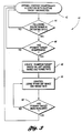
- Figure 3 is a flowchart including the method of the present invention.
-
- Referring to Figures 1-3, the preferred embodiment of the method and system of the present invention will now be described. In that regard, Figure 1 illustrates a simplified block diagram of an Adaptive Cruise Control (ACC) system, including the system of the present invention, denoted generally by
reference numeral 10. - In general, as is well known to those of ordinary skill in the art,
ACC system 10 is a closed loop control system intended to respond to potential targets in front of and in the same lane of traffic as the vehicle equipped with theACC system 10. The goal ofACC system 10 is to partially automate the continuous longitudinal control of the vehicle, thereby providing the vehicle operator with improved comfort and convenience. In that regard,ACC system 10 may operate in either a normal or a following mode. In normal mode operation, ACCsystem 10 controls the speed of the ACC equipped vehicle to the speed set by the vehicle operator as the control speed. In following mode operation,ACC system 10 controls the speed of the ACC equipped vehicle to the speed of a sensed in-path vehicle (which may be referred to as a sensed target or a primary target). - More specifically, as seen in Figure 1, the
ACC system 10 includes avehicle controller 12 provided in communication with arange sensor 14, aspeed sensor 16, ayaw rate sensor 18, auser interface 20, athrottle actuator 22, and abrake actuator 24. As previously described, thesystem 10 extends the function of conventional speed control systems. In that regard, based on range and relative velocity information obtained and/or derived from forward lookingrange sensor 14 andspeed sensor 16,vehicle controller 12 uses throttle andbrake actuators - The following interval between the ACC equipped vehicle and the sensed target is initially set at a default value (typically two seconds) upon activation of the
system 10, but may be modified by the vehicle operator to any of a number of other selectable values viauser interface 20. The default following interval is typically the maximum following interval allowed, and modification of the following interval by the vehicle operator is permitted between that maximum and a defined minimum following interval. The following interval is referred to as headway, and is defined as the range to the sensed target (in meters), divided by the speed of the ACC equipped vehicle (in meters per second).User interface 20 is also used by the vehicle operator to set the desired vehicle control speed. - As previously noted, ACC systems and methods are well known in the art. As a result, a detailed description of the general operation of
ACC system 10, including such functions as acquisition, discrimination, differentiation, selection and tracking of targets, range and relative velocity (range rate) determinations, sensor operations, and throttle and brake control is unnecessary and, for the sake of brevity, is not set forth herein. In connection with the method and system of the present invention, such functions ofACC system 10 may be undertaken in any fashion known to those of ordinary skill. - As also previously noted, while maintaining the selected following interval, existing ACC methods and systems may decelerate the ACC equipped to a speed less than a minimum operating speed threshold. In such situations, the ACC system is simply deactivated. This is typically accomplished by "fading" the vehicle brakes. That is, the vehicle brake actuators are controlled to gradually decrease to zero the hydraulic pressure applied to the vehicle brakes. Thereafter, the ACC system having been deactivated, absent intervention by the vehicle operator, the vehicle simply coasts.
- In contrast, the present invention provides, in an ACC system, a method and system for continued control of an ACC equipped vehicle when the speed of the vehicle decreases below the minimum operating speed threshold and the sensed target disappears. In that regard, the present invention adds to an ACC equipped vehicle the ability to control the vehicle speed based on a phantom target. More specifically, when maintaining the selected following interval, if the speed of the ACC equipped vehicle decreases below the minimum operating speed threshold, the present invention determines whether the sensed in-path target vehicle has disappeared (such as where the sensed target leaves the path of the ACC equipped vehicle, the ACC equipped vehicle leaves the path of the sensed target, or the sensed target reaches a sufficiently low speed that it can no longer be identified). If so, the present invention compensates for the loss of the sensed target by controlling the speed of the ACC equipped vehicle based on the range and range rate of a phantom target. The phantom target is created from the last known range and rage rate of the sensed target that has disappeared from the radar tracking files of the ACC system. Below the minimum operating speed threshold, the present invention could allow, for example, the ACC equipped vehicle to maintain braking even if the in-path sensed vehicle has disappeared. In so doing, the present invention provides the ACC equipped vehicle with a smoother, more comfortable response.
- In that regard, an example of a sensed in-path vehicle and the disappearance thereof is depicted in Figures 2a and 2b. As seen in Figure 2a, ACC equipped
vehicle 30 usesradar pattern 32 of an ACC range sensor (not shown) to identifylead vehicle 34 as a sensed target. If necessary, ACC equippedvehicle 30 automatically decelerates to maintain a selected headway setting. Such deceleration may result in the speed of ACC equippedvehicle 30 decreasing below a minimum operating threshold speed. As previously noted, in that event, the ACC system is simply deactivated, which is typically accomplished by "fading" the vehicle brakes. That is, the vehicle brake actuators are controlled to gradually decrease to zero the hydraulic pressure applied to the vehicle brakes. - As previously noted, the present invention provides, in the
ACC system 10 of Figure 1, a method and system for continued braking of the ACC equipped vehicle when the vehicle speed falls below the minimum operation speed and the sensed target disappears. More specifically, in the event the vehicle speed is less than the minimum operating speed, the method and system first determine whether the sensed target has disappeared. In that regard, referring to Figure 2b, it can be seen thatlead vehicle 34 has changed lanes, thereby disappearing fromradar pattern 32 of ACC equippedvehicle 30. A sensed target may also disappear when, for example,lead vehicle 34 continues in its present lane and ACC equippedvehicle 30 changes lanes (not shown). Still further, a sensed target may also disappear if it reaches a sufficiently low speed that it can no longer be identified. - Regardless, if the sensed target disappears, the method and system of the present invention compensate for such a disappearance by generating a phantom target having its own range and range rate values. The initial values of the range and range rate of the phantom target correspond to the last known range and range rate, respectively, of the lost sensed target. Subsequent values of the range and range rate of the phantom target are extrapolated. The method and system of the present invention then control the speed of the ACC equipped vehicle based on the range and range rate of the phantom target. One type of such control may include continued braking of the ACC equipped vehicle to reduce vehicle speed, including possibly stopping the vehicle.
- While the method and system control the speed of the ACC equipped vehicle based on the phantom target, the method and system also continue to determine whether a sensed target has been reacquired. If a sensed target is not reacquired, the method and system continue to control the speed of the ACC equipped vehicle based on the phantom target. If, however, a sensed target is reacquired, the method and system of the present invention may then permit operation of the following mode of the
ACC system 10 to resume, based on the target information (including range and range rate) of the newly acquired primary target. Such a resumption of following mode operation may include deactivation of theACC system 10, particularly where the speed of the ACC equipped vehicle is less than the minimum operating speed. As in existing ACC methods and systems, such deactivation would preferably include "fading" the vehicle brakes (i.e., gradually reducing to zero the amount of hydraulic pressure applied to the vehicle brakes). Regardless, according to the present invention, an improved response of the ACC equipped vehicle is provided. By allowing, for example, the ACC equipped vehicle to continue braking even though the sensed target has disappeared, the present invention provides the ACC equipped vehicle with a smoother, more comfortable response. - Referring again to Figure 1, the system of the present invention is preferably included in
vehicle controller 12. In that regard,vehicle controller 12 includes a receiver (not shown) capable of receiving an input signal fromspeed sensor 16 indicative of the speed of the ACC equipped vehicle.Vehicle controller 12 also includes a controller (not shown) a controller capable of determining whether the vehicle speed is less than the minimum operating speed threshold, determining whether a sensed target has disappeared if the vehicle speed is less than the minimum operating speed threshold, generating a phantom target having a range and range rate corresponding to a last known range and range rate, respectively, of the sensed target if the sensed target has disappeared, and controlling the vehicle speed based on the range and range rate of the phantom target. In that regard, to control the vehicle speed based on the range and range rate of the phantom target, the controller may be capable of reducing the vehicle speed by generating a brake control signal operative to control a brake actuator, including reducing the vehicle speed to zero. - The controller of the system of the present invention may further capable of determining whether another sensed target has been acquired, and de-activating the adaptive speed control system if another sensed target has been acquired. In that regard, to deactivate the adaptive speed control system, the controller may be capable of generating a braking control signal operative to control a brake actuator to gradually reduce to zero an amount of hydraulic pressure applied by the brake actuator. It should be noted here that the controller of the present invention (as well as
vehicle controller 12 of ACC system 10) may take the form of an appropriately programmed microprocessor, or any equivalent thereof. - Referring now to Figure 3, a flowchart including the method of the present invention is shown, depicted generally by
reference numeral 40. As seen therein, during operation, existing ACC methods include a headway maintenance algorithm which operates based on existingtarget information 42, including the range and range rate of the primary target and a selected headway value. Such an algorithm has been previously described as following mode operation and, once again, is well known to those of ordinary skill in the art. According to the method of the present invention, during such operation, it is determined whether the ACC equipped vehicle is following the sensed target at a speed below the minimum operating speed threshold of theACC system 44. If not, operation of the headway maintenance algorithm continues based on existingtarget information 42. - However, if the speed of the ACC equipped vehicle is less than the minimum operating speed, it is determined whether the primary target has disappeared 46. If not, operation of the headway maintenance algorithm once again continues based on existing
target information 42. In that event, since the speed of the ACC equipped vehicle is less than the minimum operating speed threshold, the ACC system may be deactivated, such as by "fading" the vehicle brakes to gradually decrease the braking force applied to the vehicle. - If, however, the primary target has disappeared, the method of the present invention creates a phantom target based on the last known range and range rate of the lost sensed
target 48, as described in detail above. Thereafter, according to the method of the present invention, the speed of the ACC equipped vehicle is controlled based on the phantom target, including the range and range rate of thatphantom target 50, again as previously described in detail. In that regard, such control may include continued braking of the ACC equipped vehicle to reduce vehicle speed, including up to stopping the vehicle. - Subsequently, it is determined whether a primary target has been reacquired 52. If not, control of the ACC equipped vehicle speed continues based on the phantom target, including the range and range rate of that
phantom target 50. In the event, however, that a primary target has been reacquired, then operation of the headway maintenance algorithm resumes 42, based on the target information of the newly acquired primary target. Once again, in that event, as the speed of the ACC equipped vehicle may be less than the minimum operating speed threshold, the ACC system may be deactivated, such as by "fading" the vehicle brakes to gradually decrease the braking force applied to the vehicle. - In view of the foregoing description, it can be seen that the present invention provides, in an adaptive speed control system for a vehicle, a method and system for continued vehicle control at vehicle speeds below a minimum operating speed threshold when a sensed target disappears. Such a method and system add to an ACC equipped vehicle the ability to control the vehicle speed based on the range and range rate of a phantom target created from the last known range and rage rate of the sensed target that has disappeared from the radar tracking files of the ACC system. Below the minimum operating speed threshold, such a method and system may allow, for example, the ACC equipped vehicle to maintain braking even if the in-path sensed vehicle has disappeared. In so doing, such a method and system provide the ACC equipped vehicle with a smoother, more comfortable response.
- While various embodiments of the invention have been illustrated and described, it is not intended that these embodiments illustrate and describe all possible forms of the invention. Rather, the words used in the specification are words of description rather than limitation, and it is understood that various changes may be made without departing from the scope of the invention.
Claims (10)
- A method for continued vehicle control at a vehicle speed below a minimum operating speed threshold when a sensed target disappears, using an adaptive speed control system for a vehicle, the method comprising:determining whether the vehicle speed is less than the minimum operating speed threshold;if the vehicle speed is less than the minimum operating speed, determining whether the sensed target has disappeared;if the sensed target has disappeared, generating a phantom target having a range and range rate corresponding to a last known range and range rate, respectively, of the sensed target; andcontrolling the vehicle speed based on the range and range rate of the phantom target.
- The method of claim 1 wherein controlling the vehicle speed based on the range and range rate of the phantom target comprises reducing the vehicle speed by generating a brake control signal operative to control a brake actuator.
- The method of claim 2 wherein reducing the vehicle speed includes reducing the vehicle speed to zero.
- The method of claim 1 further comprising:determining whether another sensed target has been acquired; andif another sensed target has been acquired, controlling the vehicle speed based on a range and range rate associated with the another sensed target.
- The method of claim 4 wherein controlling the vehicle speed based on the range and range rate associated with the another sensed target includes deactivating the adaptive speed control system.
- The method of claim 5 wherein deactivating the adaptive speed control system includes generating a braking control signal operative to control a brake actuator to gradually reduce to zero an amount of hydraulic pressure applied by the brake actuator.
- The method of claim 2 further comprising:determining whether another sensed target has been acquired; andif another sensed target has been acquired, controlling the vehicle speed based on a range and range rate associated with the another sensed target.
- The method of claim 7 wherein controlling the vehicle speed based on the range and range rate associated with the another sensed target includes deactivating the adaptive speed control system.
- The method of claim 8 wherein deactivating the adaptive speed control system includes generating a braking control signal operative to control a brake actuator to gradually reduce to zero an amount of hydraulic pressure applied by the brake actuator.
- The method of claim 3 further comprising:determining whether another sensed target has been acquired; andif another sensed target has been acquired, controlling the vehicle speed based on a range and range rate associated with the another sensed target.
Applications Claiming Priority (2)
| Application Number | Priority Date | Filing Date | Title |
|---|---|---|---|
| US470379 | 1999-12-22 | ||
| US09/470,379 US6161074A (en) | 1999-12-22 | 1999-12-22 | Method and system for continued vehicle control in an adaptive speed control system at vehicle speeds below a minimum operating speed when a sensed target disappears |
Publications (3)
| Publication Number | Publication Date |
|---|---|
| EP1110792A2 true EP1110792A2 (en) | 2001-06-27 |
| EP1110792A3 EP1110792A3 (en) | 2004-01-02 |
| EP1110792B1 EP1110792B1 (en) | 2005-07-20 |
Family
ID=23867399
Family Applications (1)
| Application Number | Title | Priority Date | Filing Date |
|---|---|---|---|
| EP00311067A Expired - Lifetime EP1110792B1 (en) | 1999-12-22 | 2000-12-12 | Method and system for continued vehicle control in an adaptive speed control system at vehicle speeds below a minimum operating speed when a sensed target disappears |
Country Status (4)
| Country | Link |
|---|---|
| US (1) | US6161074A (en) |
| EP (1) | EP1110792B1 (en) |
| JP (1) | JP2001206101A (en) |
| DE (1) | DE60021341T2 (en) |
Cited By (2)
| Publication number | Priority date | Publication date | Assignee | Title |
|---|---|---|---|---|
| EP1065089A3 (en) * | 1999-06-30 | 2002-02-06 | Nissan Motor Company, Limited | Vehicle following control with inhibition of braking action on loss of target |
| EP1963128A1 (en) * | 2005-12-13 | 2008-09-03 | Scania CV AB (publ) | Data generating system |
Families Citing this family (27)
| Publication number | Priority date | Publication date | Assignee | Title |
|---|---|---|---|---|
| KR20030069802A (en) | 2000-06-26 | 2003-08-27 | 스넵-온 테크놀로지스 인코포레이티드 | Alternator testing method and system using ripple detection |
| JP3646660B2 (en) * | 2001-03-26 | 2005-05-11 | 日産自動車株式会社 | Vehicle tracking control device |
| JP2003063272A (en) * | 2001-08-30 | 2003-03-05 | Hitachi Ltd | Automatic speed controller for vehicle |
| US6775605B2 (en) | 2001-11-29 | 2004-08-10 | Ford Global Technologies, Llc | Remote sensing based pre-crash threat assessment system |
| US6819991B2 (en) | 2001-11-29 | 2004-11-16 | Ford Global Technologies, Llc | Vehicle sensing based pre-crash threat assessment system |
| US6560525B1 (en) | 2002-01-02 | 2003-05-06 | Ford Global Technologies, Llc | Integrated queue assist and adaptive cruise control |
| US6708099B2 (en) * | 2002-01-17 | 2004-03-16 | Ford Global Technologies, Llc | Stop and go adaptive cruise control system |
| US6831572B2 (en) | 2002-01-29 | 2004-12-14 | Ford Global Technologies, Llc | Rear collision warning system |
| US6721659B2 (en) | 2002-02-01 | 2004-04-13 | Ford Global Technologies, Llc | Collision warning and safety countermeasure system |
| US6519519B1 (en) | 2002-02-01 | 2003-02-11 | Ford Global Technologies, Inc. | Passive countermeasure methods |
| US7009500B2 (en) | 2002-02-13 | 2006-03-07 | Ford Global Technologies, Llc | Method for operating a pre-crash sensing system in a vehicle having a countermeasure system using stereo cameras |
| US6498972B1 (en) | 2002-02-13 | 2002-12-24 | Ford Global Technologies, Inc. | Method for operating a pre-crash sensing system in a vehicle having a countermeasure system |
| US6753804B2 (en) * | 2002-05-21 | 2004-06-22 | Visteon Global Technologies, Inc. | Target vehicle identification based on the theoretical relationship between the azimuth angle and relative velocity |
| US8260514B2 (en) * | 2004-09-24 | 2012-09-04 | Continental Teves Ag & Co. Ohg | Method for supporting a brake system in case of reduced effectiveness |
| DE102005044174A1 (en) * | 2005-09-16 | 2007-03-22 | Bayerische Motoren Werke Ag | Distance-related cruise control system |
| US11285810B2 (en) | 2005-11-17 | 2022-03-29 | Invently Automotive Inc. | Vehicle power management system |
| US11370302B2 (en) | 2005-11-17 | 2022-06-28 | Invently Automotive Inc. | Electric vehicle power management system |
| DE102006046903A1 (en) * | 2006-10-04 | 2008-04-10 | Robert Bosch Gmbh | Driver assistance system and method for tracking located objects |
| EP1978432B1 (en) * | 2007-04-06 | 2012-03-21 | Honda Motor Co., Ltd. | Routing apparatus for autonomous mobile unit |
| US8311720B2 (en) * | 2009-01-09 | 2012-11-13 | Robert Bosch Gmbh | Lost target function for adaptive cruise control |
| DE102012214208A1 (en) * | 2012-08-09 | 2014-02-13 | Bayerische Motoren Werke Aktiengesellschaft | Method for operating a motor vehicle during a fully automatic vehicle guidance |
| DE102013210593B4 (en) * | 2012-08-21 | 2023-04-13 | Ford Global Technologies, Llc | Method of operating a service braking system in a vehicle |
| JP6154348B2 (en) * | 2014-03-28 | 2017-06-28 | 株式会社Soken | Travel route generator |
| US10077032B2 (en) | 2014-09-02 | 2018-09-18 | Ford Global Technologies, Llc | Method and system for reducing brake drag |
| CN106828186B (en) * | 2015-12-04 | 2019-11-22 | 北京宝沃汽车有限公司 | Electric car and its cruise control system and cruise control method |
| US10246091B2 (en) | 2016-06-13 | 2019-04-02 | Robert Bosch Gmbh | Rear monitoring for automotive cruise control systems |
| JP7168493B2 (en) * | 2018-03-23 | 2022-11-09 | 株式会社Soken | radar equipment |
Family Cites Families (6)
| Publication number | Priority date | Publication date | Assignee | Title |
|---|---|---|---|---|
| JP3233739B2 (en) * | 1993-06-30 | 2001-11-26 | マツダ株式会社 | Car driving control device |
| US5493302A (en) * | 1993-10-01 | 1996-02-20 | Woll; Jerry | Autonomous cruise control |
| DE19650168C2 (en) * | 1996-12-04 | 2001-10-04 | Volkswagen Ag | Method and device for regulating the speed of a motor vehicle |
| DE19736966C2 (en) * | 1997-08-25 | 1999-08-05 | Mannesmann Vdo Ag | Method and arrangement for determining a control object |
| JP3402173B2 (en) * | 1998-01-08 | 2003-04-28 | 日産自動車株式会社 | Automatic speed controller |
| US6259992B1 (en) * | 1998-06-03 | 2001-07-10 | Honda Giken Kogyo Kabushiki Kaisha | Vehicle safety running control system |
-
1999
- 1999-12-22 US US09/470,379 patent/US6161074A/en not_active Expired - Fee Related
-
2000
- 2000-12-12 EP EP00311067A patent/EP1110792B1/en not_active Expired - Lifetime
- 2000-12-12 DE DE60021341T patent/DE60021341T2/en not_active Expired - Fee Related
- 2000-12-15 JP JP2000381373A patent/JP2001206101A/en active Pending
Non-Patent Citations (1)
| Title |
|---|
| None |
Cited By (4)
| Publication number | Priority date | Publication date | Assignee | Title |
|---|---|---|---|---|
| EP1065089A3 (en) * | 1999-06-30 | 2002-02-06 | Nissan Motor Company, Limited | Vehicle following control with inhibition of braking action on loss of target |
| EP1963128A1 (en) * | 2005-12-13 | 2008-09-03 | Scania CV AB (publ) | Data generating system |
| EP1963128A4 (en) * | 2005-12-13 | 2010-12-15 | Scania Cv Abp | Data generating system |
| US8190346B2 (en) | 2005-12-13 | 2012-05-29 | Scania Cv Ab (Publ) | Data generating system |
Also Published As
| Publication number | Publication date |
|---|---|
| DE60021341D1 (en) | 2005-08-25 |
| US6161074A (en) | 2000-12-12 |
| DE60021341T2 (en) | 2006-04-20 |
| JP2001206101A (en) | 2001-07-31 |
| EP1110792A3 (en) | 2004-01-02 |
| EP1110792B1 (en) | 2005-07-20 |
Similar Documents
| Publication | Publication Date | Title |
|---|---|---|
| US6161074A (en) | Method and system for continued vehicle control in an adaptive speed control system at vehicle speeds below a minimum operating speed when a sensed target disappears | |
| US6212465B1 (en) | Method and system for controlling vehicle speed based on vehicle yaw rate and yaw acceleration | |
| US6591181B2 (en) | Method and device for setting the vehicle longitudinal velocity to a deired speed | |
| EP2262660B1 (en) | Following distance control device and following distance control method | |
| US6273204B1 (en) | Method and arrangement for controlling the speed of a vehicle | |
| US6094616A (en) | Method for automatically controlling motor vehicle spacing | |
| EP0798150B1 (en) | Cruise control system with vehicle following mode | |
| US8036803B2 (en) | Adaptive cruise control system for motor vehicles | |
| JP4028618B2 (en) | Method and apparatus for controlling the speed of a vehicle | |
| EP0896896A3 (en) | Cruise control system for motor vehicle | |
| EP1317359B1 (en) | Active brake control system and adaptive cruise control integration. | |
| US6285153B1 (en) | Method and system for adjusting headway in an adaptive speed control system based on road surface coefficient of friction | |
| US6393352B2 (en) | Method and system for controlling vehicle deceleration in an adaptive speed control system based on vehicle speed | |
| US7184874B2 (en) | Device for the longitudinally guiding a motor vehicle | |
| US6259985B1 (en) | Method and system for indicating vehicle braking in an adaptive speed control system | |
| US6411883B1 (en) | Vehicle cruise control with automatic set speed reduction | |
| US7228220B2 (en) | Device for adaptive distance and speed control with having torque dampening | |
| EP1112889B1 (en) | Method and system for providing a headway function to an adaptive speed control activation switch | |
| US6445153B1 (en) | Method and system for adjusting headway in an adaptive speed control system based on road surface coefficient of friction | |
| US6408241B1 (en) | Method and system for controlling vehicle speed based on vehicle yaw rate and yaw acceleration | |
| JP4109956B2 (en) | Inter-vehicle distance control device |
Legal Events
| Date | Code | Title | Description |
|---|---|---|---|
| PUAI | Public reference made under article 153(3) epc to a published international application that has entered the european phase |
Free format text: ORIGINAL CODE: 0009012 |
|
| AK | Designated contracting states |
Kind code of ref document: A2 Designated state(s): AT BE CH CY DE DK ES FI FR GB GR IE IT LI LU MC NL PT SE TR |
|
| AX | Request for extension of the european patent |
Free format text: AL;LT;LV;MK;RO;SI |
|
| PUAL | Search report despatched |
Free format text: ORIGINAL CODE: 0009013 |
|
| AK | Designated contracting states |
Kind code of ref document: A3 Designated state(s): AT BE CH CY DE DK ES FI FR GB GR IE IT LI LU MC NL PT SE TR |
|
| AX | Request for extension of the european patent |
Extension state: AL LT LV MK RO SI |
|
| 17P | Request for examination filed |
Effective date: 20040226 |
|
| AKX | Designation fees paid |
Designated state(s): DE FR GB |
|
| GRAP | Despatch of communication of intention to grant a patent |
Free format text: ORIGINAL CODE: EPIDOSNIGR1 |
|
| GRAS | Grant fee paid |
Free format text: ORIGINAL CODE: EPIDOSNIGR3 |
|
| GRAA | (expected) grant |
Free format text: ORIGINAL CODE: 0009210 |
|
| AK | Designated contracting states |
Kind code of ref document: B1 Designated state(s): DE FR GB |
|
| REG | Reference to a national code |
Ref country code: GB Ref legal event code: FG4D |
|
| REF | Corresponds to: |
Ref document number: 60021341 Country of ref document: DE Date of ref document: 20050825 Kind code of ref document: P |
|
| PG25 | Lapsed in a contracting state [announced via postgrant information from national office to epo] |
Ref country code: GB Free format text: LAPSE BECAUSE OF NON-PAYMENT OF DUE FEES Effective date: 20051212 |
|
| PLBE | No opposition filed within time limit |
Free format text: ORIGINAL CODE: 0009261 |
|
| STAA | Information on the status of an ep patent application or granted ep patent |
Free format text: STATUS: NO OPPOSITION FILED WITHIN TIME LIMIT |
|
| 26N | No opposition filed |
Effective date: 20060421 |
|
| GBPC | Gb: european patent ceased through non-payment of renewal fee |
Effective date: 20051212 |
|
| EN | Fr: translation not filed | ||
| PG25 | Lapsed in a contracting state [announced via postgrant information from national office to epo] |
Ref country code: FR Free format text: LAPSE BECAUSE OF FAILURE TO SUBMIT A TRANSLATION OF THE DESCRIPTION OR TO PAY THE FEE WITHIN THE PRESCRIBED TIME-LIMIT Effective date: 20060915 |
|
| PGFP | Annual fee paid to national office [announced via postgrant information from national office to epo] |
Ref country code: DE Payment date: 20061218 Year of fee payment: 7 |
|
| PG25 | Lapsed in a contracting state [announced via postgrant information from national office to epo] |
Ref country code: DE Free format text: LAPSE BECAUSE OF NON-PAYMENT OF DUE FEES Effective date: 20080701 |
|
| PG25 | Lapsed in a contracting state [announced via postgrant information from national office to epo] |
Ref country code: FR Free format text: LAPSE BECAUSE OF FAILURE TO SUBMIT A TRANSLATION OF THE DESCRIPTION OR TO PAY THE FEE WITHIN THE PRESCRIBED TIME-LIMIT Effective date: 20050720 |