EP1103378A1 - An improved acoustic fluid emission head and method of forming same - Google Patents
An improved acoustic fluid emission head and method of forming same Download PDFInfo
- Publication number
- EP1103378A1 EP1103378A1 EP00125022A EP00125022A EP1103378A1 EP 1103378 A1 EP1103378 A1 EP 1103378A1 EP 00125022 A EP00125022 A EP 00125022A EP 00125022 A EP00125022 A EP 00125022A EP 1103378 A1 EP1103378 A1 EP 1103378A1
- Authority
- EP
- European Patent Office
- Prior art keywords
- frame
- plate
- glass substrate
- sealing member
- printhead
- Prior art date
- Legal status (The legal status is an assumption and is not a legal conclusion. Google has not performed a legal analysis and makes no representation as to the accuracy of the status listed.)
- Granted
Links
Images


Classifications
-
- B—PERFORMING OPERATIONS; TRANSPORTING
- B41—PRINTING; LINING MACHINES; TYPEWRITERS; STAMPS
- B41J—TYPEWRITERS; SELECTIVE PRINTING MECHANISMS, i.e. MECHANISMS PRINTING OTHERWISE THAN FROM A FORME; CORRECTION OF TYPOGRAPHICAL ERRORS
- B41J2/00—Typewriters or selective printing mechanisms characterised by the printing or marking process for which they are designed
- B41J2/005—Typewriters or selective printing mechanisms characterised by the printing or marking process for which they are designed characterised by bringing liquid or particles selectively into contact with a printing material
- B41J2/01—Ink jet
- B41J2/135—Nozzles
- B41J2/14—Structure thereof only for on-demand ink jet heads
- B41J2/14008—Structure of acoustic ink jet print heads
Definitions
- This invention relates to an improved acoustic fluid emission head, e.g. an acoustic ink printhead, and a method of forming or assembling same. More particularly, the invention is directed to an acoustic ink printhead that advantageously incorporates elastomer gaskets to replace epoxy joints in the printhead and a corrugated spacer to provide focal gap control in the printhead.
- a related method for forming the printhead includes folding and spot-welding the aperture plate of the printhead to maintain the elastomer gaskets in place and, consequently, control the focal gap.
- acoustic ink printing involves the emission of a droplet of ink from a pool of ink toward a print medium. Sound waves are generated and focussed toward the surface of the ink pool to emit the droplet therefrom.
- acoustic ink printing elements may take various forms, such elements typically include a piezoelectric transducer, a lens, a cover plate having apertures formed therein to allow emission of the ink, and corresponding wiring. It is to be appreciated that approximately one thousand (1,000) or more of these elements may be disposed on a single printhead. It should also be appreciated that other fluids may be emitted such as molten metal, etc. rather than ink.
- a single acoustic element 10 includes a glass layer 12 having an electrode layer 14 disposed thereon.
- a piezoelectric layer 16 preferably formed of zinc oxide, is positioned on the electrode layer 14 and an electrode 18 is disposed on the piezoelectric layer 16.
- Electrode layer 14 and electrode 18 are connected through a surface wiring pattern representatively shown at 20 and cables 22 to a radio frequency (RF) power source 24 which generates power that is transferred to the electrodes 14 and 18.
- RF radio frequency
- a lens 26 preferably a concentric Fresnel lens, is formed on a side opposite the electrode layer 14, spaced from the lens 26 is a liquid level control plate 28, having an aperture 30 formed therein. Ink, or fluid, 32 is retained between the liquid level control plate 28 and the glass layer 12, and the aperture 30 is aligned with the lens 26 to facilitate emission of a droplet 34 from surface 36.
- the surface 36 is, of course, exposed by the aperture 30.
- the lens 26, the electrode layer 14, the piezoelectric layer 16, and the electrode 18 are formed on the glass layer 12 through known photolithographic techniques.
- the liquid level control plate 28 is subsequently positioned to be spaced from the glass layer 12 to establish a focal gap.
- the ink 32 is fed into the space between the plate 28 and the glass layer 12, e.g. the focal gap space, from an ink supply (not shown).
- Acoustic ink printheads of the type incorporating emitting elements as described above typically have components that are bonded together with epoxy material.
- Epoxy bonded heads have the disadvantages of 1) experiencing epoxy delamination by the ink and 2) requiring increased manufacturing time resulting from the excessive cure time inherent in use of epoxy materials.
- many types of epoxy materials are simply not compatible with the types of ink used in acoustic ink printing.
- Another disadvantage of the heretofore known types of acoustic emission heads is that, in such heads, it is difficult to maintain a uniform focal gap, i.e. the gap between the control plate 28 and the glass layer 12 shown in Figure 1, across the entire emitting surface of the head. Controlling the focal gap is important for purposes of precision in emitting fluid.
- the present invention contemplates a new glueless acoustic ink printhead and a method of assembling the printhead that resolves the above-referenced difficulties and others.
- a method and apparatus relating to an improved acoustic fluid emitting head e.g. an acoustic ink printhead, are provided.
- the apparatus comprises a glass substrate having lenses with emitters positioned thereon, a first frame positioned to support the glass substrate -- the first frame having a flange extending therefrom, a first plate having a first portion with apertures defined therein, a second portion and a third portion -- the apertures being positioned in alignment with the lenses of the glass substrate and separated from the lenses by a predetermined distance to establish a focal gap, a second frame positioned to support the first plate, a first sealing member disposed between the first plate and the second frame, a second sealing member disposed between the flange of the first frame and the second frame, a second plate positioned between the second portion of the first plate and the glass substrate -- the second plate having corrugations defined therein, wherein the third portion of the first plate is disposed at an angle relative to the first and second portions and is connected to the second frame, and further wherein the flange of the first frame is connected to the second frame such that the glass substrate is maintained in a position between the first frame and the first plate
- the method comprises steps of folding the first plate such that a fold demarcates the second portion from the third portion, positioning the first sealing member in the first recess of the second frame, connecting the first plate to the second frame such that the first sealing member is compressed between the third portion of the first plate and the second frame, positioning the glass substrate to be supported by the first frame, maintaining the position of the glass substrate relative to the first frame with tabs extending from the first frame, positioning the second sealing member in the second recess of the second frame, positioning the second plate on a second portion of the glass substrate, positioning the first plate over the glass substrate and the second plate such that the first portion of the first plate is in alignment with the first portion of the glass substrate such that a focal gap is established between the first portion of the first plate and the first portion of the glass substrate and such that the second plate is positioned between the second portion of the first plate and the second portion of the glass substrate and connecting the flange of the first frame to the second frame such that the second sealing member is compressed between the flange of the first frame and the
- the apparatus comprises a glass substrate having lenses of acoustic emitters positioned thereon, a first frame positioned to support the glass substrate, a plate with apertures defined therein that are aligned with the lenses, a second frame positioned to support the plate, a first sealing member disposed between the plate and the second frame, a second sealing member disposed between the first frame and the second frame and a spacer positioned between the plate and the glass substrate, wherein the plate is connected to the second frame such that first sealing member is compressed, and further wherein the first frame is connected to the second frame such that the second sealing member is compressed and the glass substrate is maintained in a position between the first frame and the spacer and the plate whereby a focal gap is maintained between the glass substrate and the spacer.
- an acoustic fluid emission head e.g. an acoustic ink printhead
- an emitting portion 114 End portions of the head (one of which is shown in simplified form) may take a variety of forms as a function of the precise head configuration, which may vary.
- the base portion 112 has included therein a variety of components well known to those versed in the field of acoustic fluid emission.
- the base portion 112 may include electronics for controlling the operation of the head and fluid delivery components, e.g. manifolds, for facilitating proper delivery of fluid to the emitting portion of the head.
- the emitting portion 114 includes an aperture plate 116 disposed thereon.
- the plate 116 has a first portion 118 that has an aperture array positioned therein, second portions 120 adjacent the first portion, and a third portion 122 that is delineated from the second portion by a fold 124. It is to be appreciated that the apertures of the aperture array align with emitters having lenses as shown in, for example, Figure 1.
- a frame 126 (preferably formed of metal) positioned to support the aperture plate 116.
- the frame 126 may take a variety of forms to achieve this objective as well as facilitate proper sealing of the printhead.
- the frame 126 preferably is disposed around the periphery of the printhead and, at its ends, generally conforms to the shape of the angled aperture plate, as will be apparent from the representative view shown in Figure 2. It should be appreciated that the frame 126 may be unitary or may be comprised of a number of components suitably joined and/or sealed.
- the aperture plate 116 is connected to the frame 126 by connections representatively shown at 128.
- the connections are shown as being disposed along the bottom, generally straight edge of the aperture plate but it may be desirable in some circumstances to provide connections elsewhere, such as along the angled side edges of the plate.
- the preferred form of the invention uses a plurality of spot welds as the connectors 128, as will be further described below, any suitable connection devices or techniques that accommodate the features of the present invention will suffice. For example, screws, pins or rivets could be suitably used in place of or in conjunction with the spot welds.
- the left side of the head that is partially obscured in the figure includes components substantially identical to those shown on the right side that is in view.
- a glass substrate 150 is supported by a frame 152.
- the glass substrate 150 extends along the length of the printhead and has positioned thereon lenses, representatively shown at 151, aligned with the apertures of the aperture array of the first portion 118 of the plate 116.
- lenses representatively shown at 151, aligned with the apertures of the aperture array of the first portion 118 of the plate 116.
- other elements of the acoustic emitters such as those shown in Figure 1 - e.g. electrodes, piezoelectric layers, etc.
- contributes of the right side of the head as shown in Figure 3 are not shown but are identical and complementary to those illustrated on the left side.
- the frame 152 may vary in configuration but, as described herein, extends around an inner periphery of the printhead and is sized and configured to support the substrate 150.
- the frame 152 preferably is generally rectangular in shape.
- the frame 152 may be comprised of a unitary structure or a number of components suitably joined and/or sealed.
- the frame 152 has connected thereto tabs representatively shown at 154 that are suitably positioned to maintain the glass substrate 150 in position. These tabs may vary in number and location and may be connected to the frame 152 in a variety of known manners.
- a cushion and seal member 156 is also disposed between the glass layer 150 and the frame 152.
- the member 156 may take a variety of forms but preferably is formed of an elastomer or foam material and is disposed along the periphery or a top portion of the frame 152.
- the frame 152 includes a flange portion 158 that extends along a bottom portion thereof to act as a deformable spring plate.
- the flange 158 is connected to the frame 126 via a connection 160.
- the connections at 160 may take a variety of forms including but not limited to spot welds, screws, pins, or rivets.
- a sealing member 162 is disposed between the flange 158 and the frame 126 around the circumference or periphery of the head. As such, the sealing member 162 lies generally in a single plane. In this regard, a recess 166 is preferably provided in the frame 126 to accommodate the sealing member 162.
- a sealing member 164 is provided between the frame 126 and the third portions 122 of the plate 116 along the length of the head and substantially along the angled edge of plate 116.
- the sealing member 164 is not disposed in a single plane but follows the shape of the plate 116, which is angled as shown in Figure 2 and 3.
- a recess 168 is provided to accommodate the sealing member 164.
- the sealing members 162 and 164 are preferably gaskets formed of an elastomer material.
- the gaskets may be shaped as o-rings or may be rectangular in form. In any configuration, the gaskets are preferably sized and configured to conform to the recess or desired shape to accomplish sealing.
- the recesses should be formed to suitably house these gaskets, maintain the position of the gaskets and allow for sufficient protrusion of the gaskets from the recesses to effect sealing.
- various sealing techniques could be used to attain the objectives of the invention, not all of which would require gaskets and/or recesses.
- a spacer plate, or spacer, 170 is provided between the plate 116 and the glass substrate 150 on both sides of the printhead.
- spacer plates 170 are positioned between the second portions 120 of the plate 116 and portions of the glass substrate that do not have lenses formed thereon.
- the spacer plates 170 each preferably has corrugations defined therein.
- a spacer plate 170 preferably is formed of 3 x 125 mil stainless steel ribbon and is corrugated to a dimension to provide a focal gap f between the first portion 118 of plate 116 and the glass substrate 150.
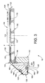
- the corrugations are aligned across the width of the head (left to right in Figure 3) to accommodate the fluid flow indicated by the arrows in Figure 3.
- the corrugations provide about 75% transparency to minimize impedance to lateral fluid flow, and the fine pitch assures even fluid flow across the head.
- the spacer plate is preferably extremely stiff and experiences negligible compression under the force necessary to maintain the focal gap.
- the spacer may take a variety of forms provided that the spacer is of a configuration and positioned to maintain the focal gap f and fluid flow.
- FIG 4 a side view of a preferred spacer plate 170 is shown.
- the plate 170 has formed therein corrugations 172 that define an effective thickness of the plate 170 to substantially correspond to the focal gap f, also shown in Figure 3.
- the corrugations 172 may be formed by any suitable techniques including those that are well known in the metal and wire bending field -- provided that the resultant plate achieves the objectives of the invention.
- the aperture plate 116 (preferably approximately 100 micrometers thick) is first folded to approximately 55° (shown for example at 124 after connection) and spot welded to the frame 126 (shown for example at 128) near its outer edges.
- the frame 126 is beveled at approximately 45° and has the sealing member 164 positioned in the recess 168.
- the angle discrepancy between the fold of the plate 116 and the frame 126 gives the aperture plate 116 a downward bow to be counteracted by the upward force of the spacer plate(s) 170.
- the glass substrate 150 containing the Fresnel lenses 151 and the elastomer cushion and seal member 156 are captured firmly by the tabs 154 of the frame 152.
- the bottom outer flange 158 of the frame 152 is preferably thin enough to deflect when the frame 152 and glass 150 are pressed up into the spacer(s) 170 and aperture plate 116. This ensures constant pressure against the spacer 170 over printhead life even if the cushion and seal member 156 takes a "set".
- the connection 160 e.g. a second set of spot welds which are suitably placed, substantially completes printhead assembly, with the exception of, for example, ink manifold and circuitry attachment. Ink entry and exit holes are not shown.
- a method 500 of assembling the head 110 is illustrated in flowchart form. It is to be appreciated, however, that the particular order of the recited steps of this method may vary as a function of, for example, the preferences of the assembler or the equipment available in the assembly process. The steps themselves may also likewise vary. An important consideration in the assembly process, however, is that sufficient compression should be applied to the components of the head when it is being assembled so that, once the connections are made to complete assembly, the components maintain their position and the focal gap is maintained.
- the plate 116 is folded such that a fold 124 demarcates the second portion 120 from the third portion 122 of the plate 116 on each side of the print head, of course (step 502).
- the sealing member 164 is advantageously positioned in the recess 168 of the frame 126 (step 504).
- the plate 116 i.e. portion 122, is connected to the frame 126 (on both sides of the plate/printhead) such that the first member 164 is compressed between the third portions 122 of the plate 116 and the frame 126 (step 506).
- the sealing member will also be compressed along the angled edge of the plate 116. Because of the differences in the angles of the fold and the bevel of the frame 126 as noted above, the third portions 122 of the plate will require a force to be applied to properly position the plate 116 for connection.
- Steps 502-506 comprise the steps necessary to connect the aperture plate to the frame 126. Before final assembly of the printhead, it is also important (before, after or concurrently with the steps 502-506) to suitably position the glass substrate 150 on the frame 152.
- the tabs 154 are positioned on, or attached to, the frame 152 at locations within the printhead that will facilitate retention of the glass substrate on the frame 152 (step 508).
- the cushion and seal member 156 is positioned on the frame 152 to be retained in position by the tabs (step 510). The substrate 150 is then pressed into position on the member 156 and between the tabs (step 512).
- a sealing member 162 is positioned in the recess 166 of the frame 126 in a plane around the periphery of the printhead and/or frame 126 (step 514).
- a spacer plate 170 is positioned between a second portion of the first plate 116 and portions of the glass substrate 150 lacking lenses (step 516).
- the plate 116 is then positioned over the glass substrate 150 and the spacer plate(s) 170 such that the first portion 118 of the first plate 116 is aligned with the lenses of the emitters on the glass substrate 150 and such that a focal gap f is established therebetween (step 518).
- the flange portion 158 of the frame 152 is then connected to the frame 126 at appropriate locations around the printhead such that the sealing member 162 is compressed between the flange 158 and the frame (step 520). In this configuration, the flange portion will act as a spring plate and provide compression to the components of the head.
- steps may be accomplished in any suitable order but, preferably, the steps entail compressing the components of the printhead together, bending the third portion of the plate into position for attachment and spot welding the components at locations such as 128 and 160 in order to maintain a suitable level of compression.
- the compressive forces maintained in the printhead generate suitable forces on the aperture plate 116 and, consequently the spacer plate, to maintain the focal gap.
Abstract
Description
- This invention relates to an improved acoustic fluid emission head, e.g. an acoustic ink printhead, and a method of forming or assembling same. More particularly, the invention is directed to an acoustic ink printhead that advantageously incorporates elastomer gaskets to replace epoxy joints in the printhead and a corrugated spacer to provide focal gap control in the printhead. A related method for forming the printhead includes folding and spot-welding the aperture plate of the printhead to maintain the elastomer gaskets in place and, consequently, control the focal gap.
- By way of background, acoustic ink printing involves the emission of a droplet of ink from a pool of ink toward a print medium. Sound waves are generated and focussed toward the surface of the ink pool to emit the droplet therefrom. While acoustic ink printing elements may take various forms, such elements typically include a piezoelectric transducer, a lens, a cover plate having apertures formed therein to allow emission of the ink, and corresponding wiring. It is to be appreciated that approximately one thousand (1,000) or more of these elements may be disposed on a single printhead. It should also be appreciated that other fluids may be emitted such as molten metal, etc. rather than ink.
- More particularly, as shown in Figure 1, a single
acoustic element 10 includes aglass layer 12 having anelectrode layer 14 disposed thereon. Apiezoelectric layer 16, preferably formed of zinc oxide, is positioned on theelectrode layer 14 and anelectrode 18 is disposed on thepiezoelectric layer 16.Electrode layer 14 andelectrode 18 are connected through a surface wiring pattern representatively shown at 20 andcables 22 to a radio frequency (RF)power source 24 which generates power that is transferred to theelectrodes electrode layer 14, alens 26, preferably a concentric Fresnel lens, is formed. Spaced from thelens 26 is a liquidlevel control plate 28, having anaperture 30 formed therein. Ink, or fluid, 32 is retained between the liquidlevel control plate 28 and theglass layer 12, and theaperture 30 is aligned with thelens 26 to facilitate emission of adroplet 34 fromsurface 36. Thesurface 36 is, of course, exposed by theaperture 30. - The
lens 26, theelectrode layer 14, thepiezoelectric layer 16, and theelectrode 18 are formed on theglass layer 12 through known photolithographic techniques. The liquidlevel control plate 28 is subsequently positioned to be spaced from theglass layer 12 to establish a focal gap. Theink 32 is fed into the space between theplate 28 and theglass layer 12, e.g. the focal gap space, from an ink supply (not shown). - Acoustic ink printheads of the type incorporating emitting elements as described above typically have components that are bonded together with epoxy material. Epoxy bonded heads have the disadvantages of 1) experiencing epoxy delamination by the ink and 2) requiring increased manufacturing time resulting from the excessive cure time inherent in use of epoxy materials. Moreover, many types of epoxy materials are simply not compatible with the types of ink used in acoustic ink printing. Another disadvantage of the heretofore known types of acoustic emission heads is that, in such heads, it is difficult to maintain a uniform focal gap, i.e. the gap between the
control plate 28 and theglass layer 12 shown in Figure 1, across the entire emitting surface of the head. Controlling the focal gap is important for purposes of precision in emitting fluid. - It would, therefore, be advantageous to provide a head that is assembled without the use of epoxy. Such a head would be easier to assemble and would avoid the problems associated with the lack of compatibility of certain epoxy materials and the ink. It would also be advantageous to provide a head with improved focal gap control.
- The present invention contemplates a new glueless acoustic ink printhead and a method of assembling the printhead that resolves the above-referenced difficulties and others.
- A method and apparatus relating to an improved acoustic fluid emitting head, e.g. an acoustic ink printhead, are provided.
- In one aspect of the invention, the apparatus comprises a glass substrate having lenses with emitters positioned thereon, a first frame positioned to support the glass substrate -- the first frame having a flange extending therefrom, a first plate having a first portion with apertures defined therein, a second portion and a third portion -- the apertures being positioned in alignment with the lenses of the glass substrate and separated from the lenses by a predetermined distance to establish a focal gap, a second frame positioned to support the first plate, a first sealing member disposed between the first plate and the second frame, a second sealing member disposed between the flange of the first frame and the second frame, a second plate positioned between the second portion of the first plate and the glass substrate -- the second plate having corrugations defined therein, wherein the third portion of the first plate is disposed at an angle relative to the first and second portions and is connected to the second frame, and further wherein the flange of the first frame is connected to the second frame such that the glass substrate is maintained in a position between the first frame and the first plate.
- In another aspect of the invention, the method comprises steps of folding the first plate such that a fold demarcates the second portion from the third portion, positioning the first sealing member in the first recess of the second frame, connecting the first plate to the second frame such that the first sealing member is compressed between the third portion of the first plate and the second frame, positioning the glass substrate to be supported by the first frame, maintaining the position of the glass substrate relative to the first frame with tabs extending from the first frame, positioning the second sealing member in the second recess of the second frame, positioning the second plate on a second portion of the glass substrate, positioning the first plate over the glass substrate and the second plate such that the first portion of the first plate is in alignment with the first portion of the glass substrate such that a focal gap is established between the first portion of the first plate and the first portion of the glass substrate and such that the second plate is positioned between the second portion of the first plate and the second portion of the glass substrate and connecting the flange of the first frame to the second frame such that the second sealing member is compressed between the flange of the first frame and the second frame.
- In another aspect of the invention, the apparatus comprises a glass substrate having lenses of acoustic emitters positioned thereon, a first frame positioned to support the glass substrate, a plate with apertures defined therein that are aligned with the lenses, a second frame positioned to support the plate, a first sealing member disposed between the plate and the second frame, a second sealing member disposed between the first frame and the second frame and a spacer positioned between the plate and the glass substrate, wherein the plate is connected to the second frame such that first sealing member is compressed, and further wherein the first frame is connected to the second frame such that the second sealing member is compressed and the glass substrate is maintained in a position between the first frame and the spacer and the plate whereby a focal gap is maintained between the glass substrate and the spacer.
- Figure 1 is an illustration of an acoustic fluid emitting element;
- Figure 2 is an illustration of a preferred embodiment of an acoustic fluid emitting head according to the present invention;
- Figure 3 is a cross-sectional view of a portion of the head of Figure 2;
- Figure 4 is a side view of a portion of the spacer plate of Figure 3; and,
- Figure 5 is a flowchart illustrating a preferred assembly operation for the head shown in Figure 2.
-
- Referring back now to the drawings wherein the showings are for purposes of illustrating the preferred embodiments of the invention only and not for purposes of limiting same, Figure 2 provides a view of the overall preferred apparatus according to the present invention. As shown in representative form, an acoustic fluid emission head, e.g. an acoustic ink printhead, 110 has a
base portion 112 and anemitting portion 114. End portions of the head (one of which is shown in simplified form) may take a variety of forms as a function of the precise head configuration, which may vary. - The
base portion 112 has included therein a variety of components well known to those versed in the field of acoustic fluid emission. For example, thebase portion 112 may include electronics for controlling the operation of the head and fluid delivery components, e.g. manifolds, for facilitating proper delivery of fluid to the emitting portion of the head. - The
emitting portion 114 includes anaperture plate 116 disposed thereon. Theplate 116 has afirst portion 118 that has an aperture array positioned therein,second portions 120 adjacent the first portion, and athird portion 122 that is delineated from the second portion by afold 124. It is to be appreciated that the apertures of the aperture array align with emitters having lenses as shown in, for example, Figure 1. - Also shown in Figure 2 is a frame 126 (preferably formed of metal) positioned to support the
aperture plate 116. Theframe 126 may take a variety of forms to achieve this objective as well as facilitate proper sealing of the printhead. Theframe 126 preferably is disposed around the periphery of the printhead and, at its ends, generally conforms to the shape of the angled aperture plate, as will be apparent from the representative view shown in Figure 2. It should be appreciated that theframe 126 may be unitary or may be comprised of a number of components suitably joined and/or sealed. - Significantly, the
aperture plate 116 is connected to theframe 126 by connections representatively shown at 128. The connections are shown as being disposed along the bottom, generally straight edge of the aperture plate but it may be desirable in some circumstances to provide connections elsewhere, such as along the angled side edges of the plate. While the preferred form of the invention uses a plurality of spot welds as theconnectors 128, as will be further described below, any suitable connection devices or techniques that accommodate the features of the present invention will suffice. For example, screws, pins or rivets could be suitably used in place of or in conjunction with the spot welds. It will be further appreciated by those skilled in the art that the left side of the head that is partially obscured in the figure includes components substantially identical to those shown on the right side that is in view. - Referring now to Figure 3 wherein a cross-sectional view of a portion of the
head 110 is depicted, it will be seen that aglass substrate 150 is supported by aframe 152. Theglass substrate 150 extends along the length of the printhead and has positioned thereon lenses, representatively shown at 151, aligned with the apertures of the aperture array of thefirst portion 118 of theplate 116. Of course, those of skill in the art will appreciate that, although not shown for simplicity, other elements of the acoustic emitters (such as those shown in Figure 1 - e.g. electrodes, piezoelectric layers, etc.) cooperate with the lenses and apertures to emit fluid from the device, as illustrated and described in connection with Figure 1. In addition, it should be recognized that significant portions of the right side of the head as shown in Figure 3 are not shown but are identical and complementary to those illustrated on the left side. - The
frame 152, preferably formed of metal, may vary in configuration but, as described herein, extends around an inner periphery of the printhead and is sized and configured to support thesubstrate 150. For example, theframe 152 preferably is generally rectangular in shape. Theframe 152 may be comprised of a unitary structure or a number of components suitably joined and/or sealed. Theframe 152 has connected thereto tabs representatively shown at 154 that are suitably positioned to maintain theglass substrate 150 in position. These tabs may vary in number and location and may be connected to theframe 152 in a variety of known manners. A cushion andseal member 156 is also disposed between theglass layer 150 and theframe 152. Themember 156 may take a variety of forms but preferably is formed of an elastomer or foam material and is disposed along the periphery or a top portion of theframe 152. - In addition, the
frame 152 includes aflange portion 158 that extends along a bottom portion thereof to act as a deformable spring plate. Theflange 158 is connected to theframe 126 via aconnection 160. As with the connection represented at 128, the connections at 160 may take a variety of forms including but not limited to spot welds, screws, pins, or rivets. - A sealing
member 162 is disposed between theflange 158 and theframe 126 around the circumference or periphery of the head. As such, the sealingmember 162 lies generally in a single plane. In this regard, arecess 166 is preferably provided in theframe 126 to accommodate the sealingmember 162. - In addition, a sealing
member 164 is provided between theframe 126 and thethird portions 122 of theplate 116 along the length of the head and substantially along the angled edge ofplate 116. In this regard, the sealingmember 164 is not disposed in a single plane but follows the shape of theplate 116, which is angled as shown in Figure 2 and 3. Similarly, arecess 168 is provided to accommodate the sealingmember 164. - It should be recognized that the sealing
members - Further, a spacer plate, or spacer, 170 is provided between the
plate 116 and theglass substrate 150 on both sides of the printhead. Preferably,spacer plates 170 are positioned between thesecond portions 120 of theplate 116 and portions of the glass substrate that do not have lenses formed thereon. Thespacer plates 170 each preferably has corrugations defined therein. In this regard, aspacer plate 170 preferably is formed of 3 x 125 mil stainless steel ribbon and is corrugated to a dimension to provide a focal gap f between thefirst portion 118 ofplate 116 and theglass substrate 150. The corrugations are aligned across the width of the head (left to right in Figure 3) to accommodate the fluid flow indicated by the arrows in Figure 3. Preferably, the corrugations provide about 75% transparency to minimize impedance to lateral fluid flow, and the fine pitch assures even fluid flow across the head. In addition, the spacer plate is preferably extremely stiff and experiences negligible compression under the force necessary to maintain the focal gap. Of course, it is to be recognized that the spacer may take a variety of forms provided that the spacer is of a configuration and positioned to maintain the focal gap f and fluid flow. - Referring now to Figure 4, a side view of a
preferred spacer plate 170 is shown. Theplate 170 has formed therein corrugations 172 that define an effective thickness of theplate 170 to substantially correspond to the focal gap f, also shown in Figure 3. It should be appreciated that thecorrugations 172 may be formed by any suitable techniques including those that are well known in the metal and wire bending field -- provided that the resultant plate achieves the objectives of the invention. - To obtain the configuration shown in Figures 2-4, the aperture plate 116 (preferably approximately 100 micrometers thick) is first folded to approximately 55° (shown for example at 124 after connection) and spot welded to the frame 126 (shown for example at 128) near its outer edges. The
frame 126 is beveled at approximately 45° and has the sealingmember 164 positioned in therecess 168. The angle discrepancy between the fold of theplate 116 and theframe 126 gives the aperture plate 116 a downward bow to be counteracted by the upward force of the spacer plate(s) 170. Meanwhile, theglass substrate 150 containing theFresnel lenses 151 and the elastomer cushion andseal member 156 are captured firmly by thetabs 154 of theframe 152. The bottomouter flange 158 of theframe 152 is preferably thin enough to deflect when theframe 152 andglass 150 are pressed up into the spacer(s) 170 andaperture plate 116. This ensures constant pressure against thespacer 170 over printhead life even if the cushion andseal member 156 takes a "set". Theconnection 160, e.g. a second set of spot welds which are suitably placed, substantially completes printhead assembly, with the exception of, for example, ink manifold and circuitry attachment. Ink entry and exit holes are not shown. - More specifically, referring now to Figure 5, a
method 500 of assembling thehead 110 is illustrated in flowchart form. It is to be appreciated, however, that the particular order of the recited steps of this method may vary as a function of, for example, the preferences of the assembler or the equipment available in the assembly process. The steps themselves may also likewise vary. An important consideration in the assembly process, however, is that sufficient compression should be applied to the components of the head when it is being assembled so that, once the connections are made to complete assembly, the components maintain their position and the focal gap is maintained. - Initially, the
plate 116 is folded such that afold 124 demarcates thesecond portion 120 from thethird portion 122 of theplate 116 on each side of the print head, of course (step 502). The sealingmember 164 is advantageously positioned in therecess 168 of the frame 126 (step 504). Theplate 116, i.e.portion 122, is connected to the frame 126 (on both sides of the plate/printhead) such that thefirst member 164 is compressed between thethird portions 122 of theplate 116 and the frame 126 (step 506). The sealing member will also be compressed along the angled edge of theplate 116. Because of the differences in the angles of the fold and the bevel of theframe 126 as noted above, thethird portions 122 of the plate will require a force to be applied to properly position theplate 116 for connection. - Steps 502-506 comprise the steps necessary to connect the aperture plate to the
frame 126. Before final assembly of the printhead, it is also important (before, after or concurrently with the steps 502-506) to suitably position theglass substrate 150 on theframe 152. In this regard, thetabs 154 are positioned on, or attached to, theframe 152 at locations within the printhead that will facilitate retention of the glass substrate on the frame 152 (step 508). Next, the cushion andseal member 156 is positioned on theframe 152 to be retained in position by the tabs (step 510). Thesubstrate 150 is then pressed into position on themember 156 and between the tabs (step 512). - Once the steps 502-506 and steps 508-512 are completed, the resultant combinations of components are ready for final assembly into the printhead. In this regard, a sealing
member 162 is positioned in therecess 166 of theframe 126 in a plane around the periphery of the printhead and/or frame 126 (step 514). In this configuration, on each side of the printhead, aspacer plate 170 is positioned between a second portion of thefirst plate 116 and portions of theglass substrate 150 lacking lenses (step 516). Theplate 116 is then positioned over theglass substrate 150 and the spacer plate(s) 170 such that thefirst portion 118 of thefirst plate 116 is aligned with the lenses of the emitters on theglass substrate 150 and such that a focal gap f is established therebetween (step 518). Theflange portion 158 of theframe 152 is then connected to theframe 126 at appropriate locations around the printhead such that the sealingmember 162 is compressed between theflange 158 and the frame (step 520). In this configuration, the flange portion will act as a spring plate and provide compression to the components of the head. - It is to be appreciated, as noted, that these steps may be accomplished in any suitable order but, preferably, the steps entail compressing the components of the printhead together, bending the third portion of the plate into position for attachment and spot welding the components at locations such as 128 and 160 in order to maintain a suitable level of compression. The compressive forces maintained in the printhead generate suitable forces on the
aperture plate 116 and, consequently the spacer plate, to maintain the focal gap. - Replacement of epoxy by elastomer seals has numerous advantages. 1) The delamination failure mode is eliminated. 2) Cure time is eliminated. 3) Elastomer lifetime projections are easily made by measuring their stiffness over time at elevated temperatures. 4) Several elastomers are reliable and chemically inert even at the higher temperatures of 150°C required for phase-change inks, including silicone, Viton and Kalrez. 5) Spring-loaded focal gap should be more stable than that of present epoxy bonded printheads. 6) The requirement to match thermal expansion of the aperture plate and printhead frame to the glass is relaxed, because there are no glue joints to shear off during assembly. Since alignment of apertures to lenses is needed only at the fixed operating temperature of the printhead, it may be possible to make both the aperture plate and the frames from stainless steel, thereby eliminating corrosion of alloy 42 in ink.
Claims (3)
- A method of forming an acoustic fluid emission head having a glass substrate having lenses of acoustic emitters positioned on a first portion thereof, a first frame, the first frame having a flange extending therefrom, a first plate having a first portion with apertures defined therein, a second portion and a third portion, a second frame having first and second recesses defined therein, a first sealing member, a second sealing member, and a second plate, the second plate having corrugations defined therein, the method comprising steps of:folding the first plate such that a fold demarcates the second portion from the third portion;positioning the first sealing member in the first recess of the second frame;connecting the first plate to the second frame such that the first sealing member is compressed between the third portion of the first plate and the second frame;positioning the glass substrate to be supported by the first frame;maintaining the position of the glass substrate relative to the first frame with tabs extending from the first frame;positioning the second sealing member in the second recess of the second frame;positioning the second plate on a second portion of the glass substrate;positioning the first plate over the glass substrate and the second plate such that the first portion of the first plate is in alignment with the first portion of the glass substrate, such that a focal gap is established between the first portion of the first plate and the first portion of the glass substrate, and such that the second plate is positioned between the second portion of the first plate and the second portion of the glass substrate; and,connecting the flange of the first frame to the second frame such that the second sealing member is compressed between the flange of the first frame and the second frame.
- An apparatus useful for emitting droplets of liquid from a surface of a pool of the liquid, the apparatus comprising:wherein the plate is connected to the second frame such that first sealing member is compressed,a glass substrate having lenses of acoustic emitters positioned thereon;a first frame positioned to support the glass substrate;a plate with apertures defined therein that are aligned with the lenses;a second frame positioned to support the plate;a first sealing member disposed between the plate and the second frame;a second sealing member disposed between the first frame and the second frame; and,a spacer positioned between the plate and the glass substrate;
wherein the first frame is connected to the second frame such that the second sealing member is compressed and the glass substrate is maintained in a position between the first frame and the spacer and the plate whereby a focal gap is maintained between the glass substrate and the plate. - The apparatus as set forth in claim 2 wherein the spacer has corrugations defined therein.
Applications Claiming Priority (2)
| Application Number | Priority Date | Filing Date | Title |
|---|---|---|---|
| US09/448,801 US6276779B1 (en) | 1999-11-24 | 1999-11-24 | Acoustic fluid emission head and method of forming same |
| US448801 | 2003-05-31 |
Publications (2)
| Publication Number | Publication Date |
|---|---|
| EP1103378A1 true EP1103378A1 (en) | 2001-05-30 |
| EP1103378B1 EP1103378B1 (en) | 2005-08-17 |
Family
ID=23781741
Family Applications (1)
| Application Number | Title | Priority Date | Filing Date |
|---|---|---|---|
| EP00125022A Expired - Lifetime EP1103378B1 (en) | 1999-11-24 | 2000-11-16 | An improved acoustic fluid emission head and method of forming same |
Country Status (4)
| Country | Link |
|---|---|
| US (1) | US6276779B1 (en) |
| EP (1) | EP1103378B1 (en) |
| JP (1) | JP4460143B2 (en) |
| DE (1) | DE60021987T2 (en) |
Cited By (2)
| Publication number | Priority date | Publication date | Assignee | Title |
|---|---|---|---|---|
| US6410899B1 (en) | 1998-06-17 | 2002-06-25 | Foveon, Inc. | Active pixel sensor with bootstrap amplification and reduced leakage during readout |
| US6882367B1 (en) | 2000-02-29 | 2005-04-19 | Foveon, Inc. | High-sensitivity storage pixel sensor having auto-exposure detection |
Families Citing this family (7)
| Publication number | Priority date | Publication date | Assignee | Title |
|---|---|---|---|---|
| EP1324823B1 (en) * | 2000-09-25 | 2007-12-26 | Picoliter, Inc. | Focused acoustic energy in the preparation and screening of combinatorial libraries |
| US20040090497A1 (en) * | 2002-11-13 | 2004-05-13 | Xerox Corporation | Acoustic ink printer |
| EP2232572A4 (en) * | 2007-12-07 | 2012-10-17 | Alion Inc | Focused acoustic printing of patterned photovoltaic materials |
| US20100184244A1 (en) * | 2009-01-20 | 2010-07-22 | SunPrint, Inc. | Systems and methods for depositing patterned materials for solar panel production |
| US11247488B2 (en) | 2019-03-08 | 2022-02-15 | Palo Alto Research Center Incorporated | Printer head for strand element printing |
| US11318757B2 (en) | 2019-07-09 | 2022-05-03 | Xerox Corporation | Method and apparatus for digital dyeing of thread |
| US11897188B2 (en) | 2020-01-30 | 2024-02-13 | Xerox Corporation | Method and system for 3D printing on fabric |
Citations (4)
| Publication number | Priority date | Publication date | Assignee | Title |
|---|---|---|---|---|
| US5111220A (en) * | 1991-01-14 | 1992-05-05 | Xerox Corporation | Fabrication of integrated acoustic ink printhead with liquid level control and device thereof |
| EP0683048A2 (en) * | 1994-05-18 | 1995-11-22 | Xerox Corporation | Lithographically defined ejection units |
| EP0683405A1 (en) * | 1994-05-18 | 1995-11-22 | Xerox Corporation | Acoustic fabrication of color filters |
| EP0692383A2 (en) * | 1994-07-11 | 1996-01-17 | Kabushiki Kaisha Toshiba | Ink jet recording device |
Family Cites Families (4)
| Publication number | Priority date | Publication date | Assignee | Title |
|---|---|---|---|---|
| JP3419822B2 (en) * | 1992-05-29 | 2003-06-23 | ゼロックス・コーポレーション | Capping structure and droplet ejector |
| US5736998A (en) * | 1995-03-06 | 1998-04-07 | Hewlett-Packard Company | Inkjet cartridge design for facilitating the adhesive sealing of a printhead to an ink reservoir |
| US5821958A (en) * | 1995-11-13 | 1998-10-13 | Xerox Corporation | Acoustic ink printhead with variable size droplet ejection openings |
| US6007183A (en) * | 1997-11-25 | 1999-12-28 | Xerox Corporation | Acoustic metal jet fabrication using an inert gas |
-
1999
- 1999-11-24 US US09/448,801 patent/US6276779B1/en not_active Expired - Lifetime
-
2000
- 2000-11-15 JP JP2000347607A patent/JP4460143B2/en not_active Expired - Fee Related
- 2000-11-16 DE DE60021987T patent/DE60021987T2/en not_active Expired - Lifetime
- 2000-11-16 EP EP00125022A patent/EP1103378B1/en not_active Expired - Lifetime
Patent Citations (4)
| Publication number | Priority date | Publication date | Assignee | Title |
|---|---|---|---|---|
| US5111220A (en) * | 1991-01-14 | 1992-05-05 | Xerox Corporation | Fabrication of integrated acoustic ink printhead with liquid level control and device thereof |
| EP0683048A2 (en) * | 1994-05-18 | 1995-11-22 | Xerox Corporation | Lithographically defined ejection units |
| EP0683405A1 (en) * | 1994-05-18 | 1995-11-22 | Xerox Corporation | Acoustic fabrication of color filters |
| EP0692383A2 (en) * | 1994-07-11 | 1996-01-17 | Kabushiki Kaisha Toshiba | Ink jet recording device |
Cited By (2)
| Publication number | Priority date | Publication date | Assignee | Title |
|---|---|---|---|---|
| US6410899B1 (en) | 1998-06-17 | 2002-06-25 | Foveon, Inc. | Active pixel sensor with bootstrap amplification and reduced leakage during readout |
| US6882367B1 (en) | 2000-02-29 | 2005-04-19 | Foveon, Inc. | High-sensitivity storage pixel sensor having auto-exposure detection |
Also Published As
| Publication number | Publication date |
|---|---|
| JP4460143B2 (en) | 2010-05-12 |
| DE60021987T2 (en) | 2006-01-26 |
| JP2001150689A (en) | 2001-06-05 |
| EP1103378B1 (en) | 2005-08-17 |
| US6276779B1 (en) | 2001-08-21 |
| DE60021987D1 (en) | 2005-09-22 |
Similar Documents
| Publication | Publication Date | Title |
|---|---|---|
| EP0723869B1 (en) | On-demand type ink jet print head | |
| EP0719642B1 (en) | An ink-jet recording head, a manufacturing method therefor, and a recording apparatus thereof | |
| JP3196811B2 (en) | Laminated ink jet recording head and method of manufacturing the same | |
| EP1103378B1 (en) | An improved acoustic fluid emission head and method of forming same | |
| US20070165077A1 (en) | Head module, liquid jetting head, liquid jetting apparatus, method of manufacturing head module, and method of manufacturing liquid jetting head | |
| JPH06234218A (en) | Lamination type ink jet recording head and manufacture thereof | |
| JP4366568B2 (en) | Liquid ejecting head and liquid ejecting apparatus | |
| JP2003145791A (en) | Ink jet printer head | |
| US7832086B2 (en) | Alignment jig, manufacturing method thereof, and method of manufacturing liquid-jet head unit | |
| JPH11268286A (en) | Ink jet head | |
| KR20010043947A (en) | Narrow-pitch connector, pitch converter, micromachine, piezoelectric actuator, electrostatic actuator, ink-jet head, ink-jet printer, liquid crystal device, and electronic apparatus | |
| JP2007190684A (en) | Head unit and liquid ejector | |
| US9889661B2 (en) | Liquid ejecting head and manufacturing method for liquid ejecting head | |
| JP2002240283A (en) | Ink jet printer head and method for manufacturing ink jet printer head | |
| JP3539653B2 (en) | Inkjet head | |
| JP2007001190A (en) | Head module, liquid ejection head, liquid ejector and method for manufacturing head module | |
| JP2001105574A (en) | Ink jet head | |
| JP2006327159A (en) | Liquid jet head and liquid jet apparatus | |
| JPH11320882A (en) | Ink jet recording head and ink jet recording apparatus | |
| JP2003025565A (en) | Line head and printer comprising it | |
| JP3412156B2 (en) | Inkjet recording head | |
| JPH10119263A (en) | Ink jet head | |
| JP2003145752A (en) | Ink jet printer head and manufacturing method therefor | |
| JPH09226118A (en) | Ink jet head | |
| JP3109013B2 (en) | Ink jet recording head and method of manufacturing the same |
Legal Events
| Date | Code | Title | Description |
|---|---|---|---|
| PUAI | Public reference made under article 153(3) epc to a published international application that has entered the european phase |
Free format text: ORIGINAL CODE: 0009012 |
|
| AK | Designated contracting states |
Kind code of ref document: A1 Designated state(s): DE FR GB |
|
| AX | Request for extension of the european patent |
Free format text: AL;LT;LV;MK;RO;SI |
|
| 17P | Request for examination filed |
Effective date: 20011130 |
|
| AKX | Designation fees paid |
Free format text: DE FR GB |
|
| GRAP | Despatch of communication of intention to grant a patent |
Free format text: ORIGINAL CODE: EPIDOSNIGR1 |
|
| GRAS | Grant fee paid |
Free format text: ORIGINAL CODE: EPIDOSNIGR3 |
|
| GRAA | (expected) grant |
Free format text: ORIGINAL CODE: 0009210 |
|
| AK | Designated contracting states |
Kind code of ref document: B1 Designated state(s): DE FR GB |
|
| REG | Reference to a national code |
Ref country code: GB Ref legal event code: FG4D |
|
| REF | Corresponds to: |
Ref document number: 60021987 Country of ref document: DE Date of ref document: 20050922 Kind code of ref document: P |
|
| ET | Fr: translation filed | ||
| PLBE | No opposition filed within time limit |
Free format text: ORIGINAL CODE: 0009261 |
|
| STAA | Information on the status of an ep patent application or granted ep patent |
Free format text: STATUS: NO OPPOSITION FILED WITHIN TIME LIMIT |
|
| 26N | No opposition filed |
Effective date: 20060518 |
|
| REG | Reference to a national code |
Ref country code: FR Ref legal event code: PLFP Year of fee payment: 16 |
|
| REG | Reference to a national code |
Ref country code: FR Ref legal event code: PLFP Year of fee payment: 17 |
|
| REG | Reference to a national code |
Ref country code: FR Ref legal event code: PLFP Year of fee payment: 18 |
|
| PGFP | Annual fee paid to national office [announced via postgrant information from national office to epo] |
Ref country code: FR Payment date: 20171020 Year of fee payment: 18 Ref country code: DE Payment date: 20171019 Year of fee payment: 18 |
|
| PGFP | Annual fee paid to national office [announced via postgrant information from national office to epo] |
Ref country code: GB Payment date: 20171020 Year of fee payment: 18 |
|
| REG | Reference to a national code |
Ref country code: DE Ref legal event code: R119 Ref document number: 60021987 Country of ref document: DE |
|
| GBPC | Gb: european patent ceased through non-payment of renewal fee |
Effective date: 20181116 |
|
| PG25 | Lapsed in a contracting state [announced via postgrant information from national office to epo] |
Ref country code: DE Free format text: LAPSE BECAUSE OF NON-PAYMENT OF DUE FEES Effective date: 20190601 Ref country code: FR Free format text: LAPSE BECAUSE OF NON-PAYMENT OF DUE FEES Effective date: 20181130 |
|
| PG25 | Lapsed in a contracting state [announced via postgrant information from national office to epo] |
Ref country code: GB Free format text: LAPSE BECAUSE OF NON-PAYMENT OF DUE FEES Effective date: 20181116 |