EP1096834A2 - Display device with luminescent elements - Google Patents
Display device with luminescent elements Download PDFInfo
- Publication number
- EP1096834A2 EP1096834A2 EP00122938A EP00122938A EP1096834A2 EP 1096834 A2 EP1096834 A2 EP 1096834A2 EP 00122938 A EP00122938 A EP 00122938A EP 00122938 A EP00122938 A EP 00122938A EP 1096834 A2 EP1096834 A2 EP 1096834A2
- Authority
- EP
- European Patent Office
- Prior art keywords
- display device
- branch
- dij
- semiconductor components
- circuit
- Prior art date
- Legal status (The legal status is an assumption and is not a legal conclusion. Google has not performed a legal analysis and makes no representation as to the accuracy of the status listed.)
- Withdrawn
Links
Images


Classifications
-
- B—PERFORMING OPERATIONS; TRANSPORTING
- B61—RAILWAYS
- B61L—GUIDING RAILWAY TRAFFIC; ENSURING THE SAFETY OF RAILWAY TRAFFIC
- B61L5/00—Local operating mechanisms for points or track-mounted scotch-blocks; Visible or audible signals; Local operating mechanisms for visible or audible signals
- B61L5/12—Visible signals
- B61L5/18—Light signals; Mechanisms associated therewith, e.g. blinders
- B61L5/1809—Daylight signals
- B61L5/1881—Wiring diagrams for power supply, control or testing
-
- H—ELECTRICITY
- H05—ELECTRIC TECHNIQUES NOT OTHERWISE PROVIDED FOR
- H05B—ELECTRIC HEATING; ELECTRIC LIGHT SOURCES NOT OTHERWISE PROVIDED FOR; CIRCUIT ARRANGEMENTS FOR ELECTRIC LIGHT SOURCES, IN GENERAL
- H05B45/00—Circuit arrangements for operating light-emitting diodes [LED]
- H05B45/30—Driver circuits
- H05B45/357—Driver circuits specially adapted for retrofit LED light sources
- H05B45/3574—Emulating the electrical or functional characteristics of incandescent lamps
-
- H—ELECTRICITY
- H05—ELECTRIC TECHNIQUES NOT OTHERWISE PROVIDED FOR
- H05B—ELECTRIC HEATING; ELECTRIC LIGHT SOURCES NOT OTHERWISE PROVIDED FOR; CIRCUIT ARRANGEMENTS FOR ELECTRIC LIGHT SOURCES, IN GENERAL
- H05B45/00—Circuit arrangements for operating light-emitting diodes [LED]
- H05B45/40—Details of LED load circuits
- H05B45/44—Details of LED load circuits with an active control inside an LED matrix
-
- H—ELECTRICITY
- H05—ELECTRIC TECHNIQUES NOT OTHERWISE PROVIDED FOR
- H05B—ELECTRIC HEATING; ELECTRIC LIGHT SOURCES NOT OTHERWISE PROVIDED FOR; CIRCUIT ARRANGEMENTS FOR ELECTRIC LIGHT SOURCES, IN GENERAL
- H05B45/00—Circuit arrangements for operating light-emitting diodes [LED]
- H05B45/50—Circuit arrangements for operating light-emitting diodes [LED] responsive to malfunctions or undesirable behaviour of LEDs; responsive to LED life; Protective circuits
- H05B45/52—Circuit arrangements for operating light-emitting diodes [LED] responsive to malfunctions or undesirable behaviour of LEDs; responsive to LED life; Protective circuits in a parallel array of LEDs
-
- B—PERFORMING OPERATIONS; TRANSPORTING
- B61—RAILWAYS
- B61L—GUIDING RAILWAY TRAFFIC; ENSURING THE SAFETY OF RAILWAY TRAFFIC
- B61L2207/00—Features of light signals
- B61L2207/02—Features of light signals using light-emitting diodes (LEDs)
Definitions
- the invention relates to a display device according to the preamble of claim 1, in particular for use in a system for traffic regulation, control or monitoring for vehicles, for example in a traffic light.
- Such a display device is designed for the longest possible service life and has been tested, like all other lights, it is subject to certain failures that impair or can lead to the shutdown of the display device.
- the display device to prevent damage on people or vehicles or objects, i.e. used as a safety signal there must be a monitoring device assigned to the display device, which recognize a defect in the display device and corresponding immediate Measures should activate.
- the lighting elements by semiconductor components and are constructed in particular by light emitting diodes, is the constructive and circuitry
- the expense of such a monitoring device is disadvantageous.
- one has Semiconductor components compared to such light fields formed from incandescent lamps one more homogeneous over the entire surface and thus clearer from a distance Recognizability above all the advantage that only a very large number of defective light-emitting diodes become one cause noticeable loss of information.
- a suitable wiring of the LEDs and formation of the circuit controlling this can even with several defects of the Light emitting diodes prevent a decrease in the overall light intensity.
- any individual row of LEDs can be monitored individually for failure and when exceeded a certain limit, for example if the LEDs are defective by more than 20% Display device can be completely switched off via an automatic switch-off.
- incandescent lamp arrangements is essential in terms of circuitry Simpler: Since only the two operating states are intact with incandescent lamps (filament OK) and defective (filament has burned out), but no intermediate states in the characteristics of a display device based on incandescent lamps are Monitoring devices are extremely simple in terms of circuitry and are limited in Essentially on the determination of a binary yes-no state. The one at traffic lights with incandescent lamp signals previously used, extremely constructive and circuit-wise simply constructed monitoring devices are, however, in such display devices, in which the lighting elements are formed by semiconductor components, so far not useable.
- the invention has for its object a display device of the generic type Type in which the lighting elements are designed as semiconductor components to be put in a plant for traffic regulation, control or monitoring for vehicles, in particular a traffic light in connection with the conventional ones there structurally simpler monitoring devices for recording a total failure the display device can be used, d.
- the display device after the The invention is said to have a failure characteristic that largely corresponds to the failure characteristic of incandescent lamp arrangements.
- the semiconductor components Circuit of a constant current device is assigned such that the sum of the in electrical sub-currents flowing in the secondary branches have a predetermined constant value owns.
- the constant current device by a single Main branch of the constant current source provided from the circuit formed by the semiconductor components educated.
- a control circuit device assigned to the semiconductor components provided that if a flowing in a secondary branch is exceeded Partial current around a predetermined current threshold a blocking or deactivation of the relevant branch, and after exceeding a predetermined number a blocking of blocked or deactivated secondary branches in immediate succession or deactivation of all other secondary branches and thus the entire display device controls.
- the invention is based on the finding that if a partial current flowing in a secondary branch is exceeded by a predetermined current threshold value, not only does the affected group of lighting elements fail, but there is an abrupt blocking or deactivation, that is to say at extremely short time intervals that are barely measurable all other secondary branches and thus the entire display device, and in this way the display device according to the invention has a failure characteristic that is comparable to a failure characteristic known in the case of an incandescent lamp arrangement.
- the display device according to the invention can therefore be coupled directly and without further constructive or circuitry measures and expenditure to a monitoring device previously used in systems for traffic regulation, control or monitoring, which monitors a total failure of the display device via a simple current evaluation as in one Filament breakage "detected.
- the invention eliminates the need to regularly check the current lighting status the display device by measuring current flow changes.
- Display device is created in a safe and clear situation of which only two conditions have to be determined, namely whether current flows in the main branch and thus a safe overall light signal that is uniformly defined in terms of brightness and luminance exists, or no current flows in the main branch or that the display device does not more shines. Small current changes that are difficult to measure do not have to be monitored, as is the case with the prior art.
- Another advantage is that the display device according to the invention is flexible can be handled by designing the control circuit device and the individual fuse elements in each secondary branch of the semiconductor components formed circuit can be determined exactly at which light field decay the display device should switch off automatically.
- the display device is not only capable of high-resistance failures of semiconductor components, but now also takes into account low-resistance failures be, whereby the security of the display device is further increased.
- a high impedance Failure of a light element causes the total electrical resistance of the affected Secondary branch is infinite and the partial current flowing therein becomes zero. The partial flows in the remaining secondary branches rise accordingly, accompanying this with the increase in light intensity, etc. as described above.
- the branch in question remains intact overall; it flows in Partial current that is only slightly lower than before the low-resistance failure. Only with several low-resistance failures, the partial current in the relevant branch is so large that the safety element in question triggers and the secondary branch concerned completely locks or deactivates.
- the constant current source device by a single in the main branch of the circuit formed from the semiconductor components provided constant current source is formed.
- any suitable ones are suitable Circuits for such a constant current source.
- a technically simple and Inexpensive constant current sources are achieved with a transistor whose base is based on a predetermined control voltage and its collector on a main current line or in Main branch of the circuit formed from the semiconductor components is connected.
- the An electrical resistance determining the current is assigned to the emitter.
- Constant current source has the advantage that it is not based on a specific circuit of the display device is restricted.
- the embodiment shown in the figures shows a display device according to the invention 1 for a changing information, the information by selection or Combination of individual lighting elements L arranged on a carrier T is shown is, and the lighting elements L are formed by semiconductor devices Dij, in particular from light emitting diodes or other integrated semiconductor circuits with components for Light emission.
- the semiconductor components Dij are in several circuit groups, shown in Case 24 of such groups, with only six groups shown in more detail, switched, each circuit group current-wise a secondary branch N1, N2, ..., N6 of a main branch H forms with node K.
- each secondary branch N there is a multitude of light elements, for example, a number of ten lighting elements Di1 to Di10 connected in series (i denotes the number of the group or branch, j the number of the Light element in the secondary branch).
- the consisting of the semiconductor devices Dij Circuit is assigned to a constant current device 3 such that the sum of the in the sub-branches N1, N2, ... electrical partial currents flowing a predetermined constant Has value, regardless of the flow in the secondary branches Partial flow values.
- It is a control circuit device assigned to the semiconductor components Dij F is provided which, if one in a secondary branch N1, N2, ...
- control circuit device F by individual fuse elements F1, F2, ... in each secondary branch N1, N2, ... the circuit formed from the semiconductor devices Dij.
- These security elements in the simplest case provide fuses with predetermined breakdown current values represents, for example with 125 V / 50 mA each with a number of 24 independent Luminous element groups of 10 LEDs each, the total current in the main branch (operating current the constant current source 3) is typically 0.5 A.
- the display device 1 according to the invention is connected to the potential U + or ground potential GND of a DC supply voltage and to a monitoring device 2 previously used in systems for traffic regulation, control or monitoring, namely the monitoring device 2 is connected to the Primary side of a transformer or a transformer Tr coupled, the secondary side of which is coupled to the circuit according to the invention via a rectifier G1.
- the peculiarity of the display device 1 according to the invention is precisely that it can be coupled to a monitoring circuit 2, which has hitherto been used in traffic lights, and which monitors a total failure of the display device 1 via a simple current evaluation, as in a case Broken filament ".
- the functioning of the display device 1 according to the invention is as follows. In normal operation flows over each branch branch N1, N2, ... through the series connection of light-emitting diodes a group and one provided in each branch, the adaptation of the branches with each other due to manufacturing tolerances serving ohmic resistance R1, R2, ... determined total resistance of the specified partial current, the sum of all partial currents flowing in the secondary branches equal to that from the constant current source 3 delivered total constant current in the main branch H is.
- a high-resistance failure A lighting element Dij has the result that the entire group i or the secondary branch Ni fails, d. H. the partial current flowing in the secondary branch Ni becomes zero.
- the partial flows flowing in the remaining secondary branches assume higher values and correspondingly the luminosity of the luminous elements loaded with a higher partial current increases.
- Luminosity weakening due to failure of one or more groups or secondary branches is thus due to a larger current surcharge of those still in operation Secondary branches compensated.
- the total current is thus divided between the remaining branches while raising the partial flows.
- a progression of the failures of lighting elements leads to successive increases in the partial flows until the partial flows
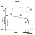
- Function of the display device is therefore essential that the failure characteristic the display device according to the embodiment approximately that of an incandescent lamp arrangement corresponds to how it is based on the schematic characteristic curves 7, 8, 9 in FIG. 3 is shown.
- the time t is plotted to the right, the Time axis is not shown linearly, but the three areas that are completely different in time Year range, hour range and millisecond range. Up are in arbitrary units each have the physical parameters total current, total light intensity and number of intact rows, or secondary branches, where for reasons of the respective 100% values are arranged offset so that they can be better represented. You watch four areas A, B, C and D in the characteristic curves 7, 8, 9.
- Area A corresponds to the normal one Operating state of the display device without any failure
- area B shows the gradually increasing failure of some individual lighting elements or secondary branches, which, however, is not yet an undetected luminosity weakening that is questionable in terms of safety results in area D being the total failure of the display device specified.
- the transition area C with an almost vertical flank is interesting below, which is only the sudden failure of the entire display device after triggering a further securing element deactivated after exceeding the predetermined number Identifies secondary branches.
- This state can be registered by means of a monitoring device 2 customary in technology and reported to a head office. The staff is then asked to identify the person concerned Exchange display device.
Abstract
Description
Die Erfindung betrifft eine Anzeigevorrichtung nach dem Oberbegriff des Anspruches 1, insbesondere
zur Verwendung in einer Anlage zur Verkehrs-Regelung, -Steuerung, oder -Überwachung
für Fahrzeuge, beispielsweise in einer Verkehrsampel.The invention relates to a display device according to the preamble of
Obzwar eine derartige Anzeigevorrichtung für eine höchstmögliche Lebensdauer ausgelegt und geprüft ist, unterliegt sie wie alle andere Leuchten gewissen Ausfällen, die zur Beeinträchtigung oder zur Abschaltung der Anzeigevorrichtung führen können. Gerade in den hier besonders relevanten Fällen, bei denen die Anzeigevorrichtung zur Abwendung von Schäden an Personen oder Fahrzeugen bzw. Gegenständen, also als Sicherheitssignal eingesetzt wird, muss eine der Anzeigevorrichtung zugeordnete Überwachungseinrichtung vorhanden sein, welche einen Defekt der Anzeigevorrichtung erkennen und entsprechende unverzügliche Maßnahmen aktivieren soll.Although such a display device is designed for the longest possible service life and has been tested, like all other lights, it is subject to certain failures that impair or can lead to the shutdown of the display device. Especially here particularly relevant cases in which the display device to prevent damage on people or vehicles or objects, i.e. used as a safety signal, there must be a monitoring device assigned to the display device, which recognize a defect in the display device and corresponding immediate Measures should activate.
Namentlich bei einer gattungsgemäßen Anzeigevorrichtung mit mehreren auf einem Träger angeordneten Leuchtelementen, wobei die Leuchtelemente durch Halbleiterbauelemente und insbesondere durch Leuchtdioden ausgebildet sind, ist der konstruktive und schaltungstechnische Aufwand für eine solche Überwachungseinrichtung nachteilig. Bekanntlich hat ein aus Halbleiterbauelementen gegenüber solchen aus Glühlampen ausgebildeten Leuchtfeldern neben einer über die gesamte Fläche homogenere und damit auch aus weiter Entfernung deutlichere Erkennbarkeit vor allem den Vorteil, dass erst sehr viele defekte Leuchtdioden zu einem erkennbaren Informationsverlust führen. Durch eine geeignete Beschaltung der Leuchtdioden und Ausbildung der diese steuernden Schaltung kann selbst bei mehrerer Defekten der Leuchtdioden eine Abnahme der gesamten Lichtstärke verhindert werden. Durch die dezentrale Anordnung der gruppenweise geschalteten Leuchtdioden-Reihen kann weiterhin vermieden werden, dass Teilflächen des Leuchtfeldes dunkel werden. Es kann beispielsweise jede einzelne Leuchtdioden-Reihe einzeln auf Ausfall überwacht werden, und bei Überschreiten eines bestimmten Grenzwertes, beispielsweise bei mehr als 20 % defekten Leuchtdioden die Anzeigevorrichtung über eine Abschaltautomatik vollständig abgeschalten werden.Especially in the case of a generic display device with several on one carrier arranged lighting elements, the lighting elements by semiconductor components and are constructed in particular by light emitting diodes, is the constructive and circuitry The expense of such a monitoring device is disadvantageous. As is well known, one has Semiconductor components compared to such light fields formed from incandescent lamps one more homogeneous over the entire surface and thus clearer from a distance Recognizability above all the advantage that only a very large number of defective light-emitting diodes become one cause noticeable loss of information. By a suitable wiring of the LEDs and formation of the circuit controlling this can even with several defects of the Light emitting diodes prevent a decrease in the overall light intensity. By the decentralized Arrangement of the rows of light-emitting diodes switched in groups can also be avoided parts of the illuminated field become dark. For example, any individual row of LEDs can be monitored individually for failure and when exceeded a certain limit, for example if the LEDs are defective by more than 20% Display device can be completely switched off via an automatic switch-off.
Demgegenüber ist die Überwachung von Glühlampenanordnungen schaltungstechnisch wesentlich einfacher: Da es bei Glühlampen nur die beiden Betriebszustände intakt (Glühfaden in Ordnung) und defekt (Glühfaden ist durchgebrannt) gibt, jedoch keinerlei Zwischenzustände in der Charakteristik einer auf Glühlampen basierenden Anzeigevorrichtung gibt, sind deren Überwachungseinrichtungen schaltungstechnisch äußerst einfach und beschränken sich im Wesentlichen auf das Feststellen eines binären Ja-Nein-Zustandes. Die bei Verkehrsampeln mit Glühlampensignalen bislang verwendeten, konstruktiv und schaltungstechnisch äußerst einfach aufgebauten Überwachungseinrichtungen sind jedoch bei solchen Anzeigevorrichtungen, bei denen die Leuchtelemente durch Halbleiterbauelemente ausgebildet sind, bislang nicht verwendbar.In contrast, the monitoring of incandescent lamp arrangements is essential in terms of circuitry Simpler: Since only the two operating states are intact with incandescent lamps (filament OK) and defective (filament has burned out), but no intermediate states in the characteristics of a display device based on incandescent lamps are Monitoring devices are extremely simple in terms of circuitry and are limited in Essentially on the determination of a binary yes-no state. The one at traffic lights with incandescent lamp signals previously used, extremely constructive and circuit-wise simply constructed monitoring devices are, however, in such display devices, in which the lighting elements are formed by semiconductor components, so far not useable.
Die Ausfallcharaktenstik bislang bekannter Anzeigevorrichtungen mit Halbleiterbauelementen als Leuchtelementen ist wesentlich komplexer gegenüber einer einfachen Ausfallcharakteristik von Glühlampenanordnungen. Mit den bekannten Überwachungsmöglichkeiten kann ohne einen besonderen, erheblichen Schaltungsaufwand, nicht eindeutig auf den Leuchtzustand einer der Leuchtdioden geschlossen werden. Denn die für die Funktion von Leuchtdioden erforderliche Ansteuerung, die Leuchtschaltung an sich sowie etwaige andere Baugruppen oder Bausteine der Überwachungseinrichtung haben zwangsläufig auch eine Eigenstromaufnahme, die bei einem Defekt undefiniert ist und einen Stromfluss erzeugen kann, der als (ordnungsgemäßes) Leuchten interpretiert werden kann, obwohl bereits eine oder mehrere Leuchtdioden ausgefallen sind. Bei bestimmten Anwendungen, wie insbesondere bei Verkehrsampeln ist es zusätzlich notwendig, sicherzustellen, dass eine Mindeststrahlungsintensität und eine Mindestgleichmäßigkeit des Leuchtfeldes aufrechterhalten bleiben. Die Stromflussänderungen sind jedoch in der Regel relativ klein, so dass die Restleuchtintensität und die Gleichmäßigkeit des Leuchtfeldes unter Umständen nicht genau bestimmt und damit gegebenenfalls eine Sicherheitsabschaltung nicht zuverlässig durchgeführt werden kann.The failure characteristics of previously known display devices with semiconductor components as lighting elements is much more complex than a simple failure characteristic of incandescent lamp assemblies. With the known monitoring options can without a special, considerable circuit effort, not clearly on the lighting state one of the LEDs can be closed. Because that for the function of LEDs required control, the lighting circuit itself and any other modules or modules of the monitoring device also necessarily have their own power consumption, which is undefined in the event of a defect and can generate a current flow which is as (proper) glow can be interpreted, although one or more already LEDs have failed. In certain applications, such as traffic lights in particular it is additionally necessary to ensure that there is a minimum radiation intensity and a minimum uniformity of the illuminated field is maintained. The current flow changes are usually relatively small, so that the residual light intensity and the Uniformity of the luminous field may not be precisely determined and therefore possibly a safety shutdown cannot be performed reliably.
Die bekannten auf Halbleiterbauelemente basierenden Anzeigevorrichtungen berücksichtigen in der Regel nur sogenannte hochohmige Ausfälle, bei denen das defekte Halbleiterbauelement hochohmig wird, d. h. der durch das defekte Halbleiterbauelement fließende Strom wird Null. Niederohmige Ausfälle, bei denen der Widerstandswert des defekten Halbleiterbauelementes Null wird, werden mit bekannten Anzeigevorrichtungen in der Regel vernachlässigt, da diese im Verhältnis zu hochohmigen Ausfällen weniger häufig vorkommen. Gleichwohl wäre es an sich wünschenswert, auch die seltener vorkommenden niederohmigen Ausfälle von Halbleiterbauelementen ebenfalls berücksichtigen zu können, um die Sicherheit der Anzeigevorrichtung weiterhin zu verbessern.Take into account the known display devices based on semiconductor components usually only so-called high-resistance failures, in which the defective semiconductor component becomes high impedance, d. H. the current flowing through the defective semiconductor device Zero. Low-resistance failures in which the resistance value of the defective semiconductor component Becomes zero, are generally neglected with known display devices, since these are less common in relation to high-resistance failures. Nevertheless it would be desirable in itself, also the less common low-resistance failures of semiconductor components can also be considered to ensure the safety of the display device continue to improve.
Der Erfindung liegt die Aufgabe zugrunde, eine Anzeigevorrichtung der gattungsgemäßen Art, bei denen die Leuchtelemente als Halbleiterbauelemente ausgebildet sind, zur Verfügung zu stellen, welche in einer Anlage zur Verkehrs-Regelung, -Steuerung, oder -Überwachung für Fahrzeuge, insbesondere eine Verkehrsampel in Verbindung mit den dortigen, herkömmlichen, konstruktiv einfacheren Überwachungseinrichtungen zur Erfassung eines Gesamtausfalles der Anzeigevorrichtung verwendet werden kann, d. h. die Anzeigevorrichtung nach der Erfindung soll eine Ausfallcharakteristik besitzen, die weitgehend der Ausfallcharakteristik von Glühlampenanordnungen entspricht.The invention has for its object a display device of the generic type Type in which the lighting elements are designed as semiconductor components to be put in a plant for traffic regulation, control or monitoring for vehicles, in particular a traffic light in connection with the conventional ones there structurally simpler monitoring devices for recording a total failure the display device can be used, d. H. the display device after the The invention is said to have a failure characteristic that largely corresponds to the failure characteristic of incandescent lamp arrangements.
Die Lösung der Aufgabe gelingt mit den kennzeichnenden Merkmalen des Anspruches 1.The problem is solved with the characterizing features of
Erfindungsgemäß ist vorgesehen, dass die aus den Halbleiterbauelementen bestehende Schaltung einer Konstantstromeinrichtung dergestalt zugeordnet ist, dass die Summe der in den Nebenzweigen fließenden elektrischen Teilströme einen vorbestimmten konstanten Wert besitzt. Von besonderem Vorteil ist die Konstantstromeinrichtung durch eine einzige im Hauptzweig der aus den Halbleiterbauelementen gebildeten Schaltung vorgesehenen Konstantstromquelle ausgebildet.According to the invention, it is provided that the semiconductor components Circuit of a constant current device is assigned such that the sum of the in electrical sub-currents flowing in the secondary branches have a predetermined constant value owns. Of particular advantage is the constant current device by a single Main branch of the constant current source provided from the circuit formed by the semiconductor components educated.
Dem Prinzip der Erfindung folgend ist eine den Halbleiterbauelementen zugeordnete Steuerschaltungseinrichtung vorgesehen, die bei Überschreitung eines in einem Nebenzweig fließenden Teilstromes um einen vorbestimmten Stromschwellwert eine Sperrung bzw. Deaktivierung des betreffenden Nebenzweiges, und nach Überschreiten einer vorbestimmten Anzahl von gesperrten bzw. deaktivierten Nebenzweige in unmittelbar zeitlicher Folge eine Sperrung bzw. Deaktivierung aller weiteren Nebenzweige und damit der gesamten Anzeigevorrichtung steuert.Following the principle of the invention is a control circuit device assigned to the semiconductor components provided that if a flowing in a secondary branch is exceeded Partial current around a predetermined current threshold a blocking or deactivation of the relevant branch, and after exceeding a predetermined number a blocking of blocked or deactivated secondary branches in immediate succession or deactivation of all other secondary branches and thus the entire display device controls.
Mit der erfindungsgemäßen Schaltungsanordnung gelingt es zum Einen, dass im Betrieb
durch den Ausfall einzelner Leuchtelemente keine unerkannte sicherheitstechnisch bedenkliche
Leuchtkraftschwächung auftritt. Fallen auf der anderen Seite im Laufe der Zeit einzelne
Leuchtelemente durch hochohmige Unterbrechung aus, so wird die gesamte Leuchtkraft der
Anzeigevorrichtung kaum geschwächt, denn es werden die noch in Betrieb befindlichen Nebenzweige
von Leuchtelementen mit einem größeren Teilstrom beaufschlagt, wodurch eine
Kompensation des Leuchtkraftverlustes erreicht wird. Selbst der Ausfall einer oder mehrerer
Nebenzweige führt noch nicht zu einem Totalausfall der Anzeigevorrichtung, da die Teilströme
in den verbleibenden, noch intakten Nebenzweigen selbsttätig so weit angehoben werden,
dass die von den noch intakten Leuchtelementen abgestrahlte Lichtintensität erhöht wird
und die aufgrund des Ausfalls einer oder mehrerer Nebenzweige einhergehenden Leuchtkraftschwächung
kompensiert wird. Erst nach Überschreiten einer vorbestimmten Anzahl gesperrter
bzw. deaktivierter Nebenzweige wird ein Sicherungselement in einem bestimmten
Nebenzweig aufgrund des darin nun fließenden übermäßigen Teilstromes ansprechen, und
letztendlich die Sicherungselemente der verbleibenden Nebenzweige von Leuchtelementen
auslösen und die Anzeigevorrichtung zur automatischen Abschaltung bringen. Dann liefert
die Anzeigevorrichtung ein Ausfallsignal, welches von einer Überwachungseinrichtung erfasst
werden kann. Der Erfindung liegt hierbei die Erkenntnis zugrunde, dass bei Überschreitung
eines in einem Nebenzweig fließenden Teilstromes um einen vorbestimmten Stromschwellwert
nicht nur ein Ausfall der betroffenen Gruppe von Leuchtelementen einhergeht,
sondern eine schlagartige, d. h. in zeitlich äußerst kurzen, kaum meßbaren Abständen erfolgende
Sperrung bzw. Deaktivierung aller weiteren Nebenzweige und damit der gesamten Anzeigevorrichtung
erfolgt, und auf diese Weise die erfindungsgemäße Anzeigevorrichtung eine
Ausfallcharakteristik besitzt, die mit einer bei Glühlampenanordnung bekannten Ausfallcharakteristik
vergleichbar ist. Von besonderem Vorteil ist die erfindungsgemäße Anzeigevorrichtung
daher unmittelbar und ohne weitere konstruktive bzw. schaltungstechnische Maßnahmen
und Aufwendungen mit einer bisher bei Anlagen zur Verkehrs-Regelung, -Steuerung,
oder -Überwachung verwendeten Überwachungseinrichtung koppelbar, welche einen Gesamtausfall
der Anzeigevorrichtung über eine einfachste Stromauswertung wie bei einem
![]()
![]()
Durch die Erfindung erübrigt sich eine regelmäßige Kontrolle des gegenwärtigen Leuchtzustandes des Anzeigevorrichtung durch Messen von Stromflußänderungen. Mit der erfindungsgemäßen Anzeigevorrichtung wird eine sichere und eindeutige Situation geschaffen, bei der nur zwei Zustände festgestellt werden müssen, nämlich ob Strom im Hauptzweig fließt und damit ein in Helligkeit und Leuchtdichte gleichmäßig definiertes sicheres Gesamtleuchtsignal besteht, oder im Hauptzweig kein Strom fließt bzw. dass die Anzeigevorrichtung nicht mehr leuchtet. Schwer meßbare kleine Stromänderungen müssen somit nicht überwacht werden, wie es beim Stand der Technik der Fall ist.The invention eliminates the need to regularly check the current lighting status the display device by measuring current flow changes. With the invention Display device is created in a safe and clear situation of which only two conditions have to be determined, namely whether current flows in the main branch and thus a safe overall light signal that is uniformly defined in terms of brightness and luminance exists, or no current flows in the main branch or that the display device does not more shines. Small current changes that are difficult to measure do not have to be monitored, as is the case with the prior art.
Ein weiterer Vorteil besteht darin, dass die Anzeigevorrichtung nach der Erfindung flexibel gehandhabt werden kann, indem über die Auslegung der Steuerschaltungseinrichtung und deren einzelnen Sicherungselemente in jedem Nebenzweig der aus den Halbleiterbauelementen gebildeten Schaltung genau bestimmbar ist, bei welchem Leuchtfeldzerfall die Anzeigevorrichtung automatisch ausschalten soll.Another advantage is that the display device according to the invention is flexible can be handled by designing the control circuit device and the individual fuse elements in each secondary branch of the semiconductor components formed circuit can be determined exactly at which light field decay the display device should switch off automatically.
Durch die Zuordnung eines einzelnen Sicherungselementes in jedem Nebenzweig der aus den Halbleiterbauelementen gebildeten Schaltung wird erreicht, dass nach Ausfall eines vorbestimmten Prozentsatzes der Gruppen von Leuchtelementen durch Überlastung der Sicherungselemente der noch funktionierenden Strompfade die gesamte Anzeigevorrichtung automatisch ausschaltet und damit die Situation in einen sicheren Zustand gebracht wird. Damit kann über eine bekannte Überwachungseinrichtung der Ausfall in üblicher Weise signalisiert werden, um das Auswechseln der Anzeigevorrichtung veranlassen zu können.By assigning a single fuse element in each secondary branch from the Semiconductor components formed circuit is achieved that after failure of a predetermined Percentage of groups of lighting elements due to overloading of the fuse elements the still functioning current paths automatically the entire display device switches off and the situation is brought into a safe state. In order to the failure can be signaled in the usual way via a known monitoring device to be able to arrange for the replacement of the display device.
Mit der erfindungsgemäßen Anzeigevorrichtung können nicht lediglich hochohmige Ausfälle von Halbleiterbauelementen, sondern nunmehr auch niederohmige Ausfälle berücksichtigt werden, wodurch die Sicherheit der Anzeigevorrichtung weiterhin erhöht wird. Ein hochohmiger Ausfall eines Leuchtelementes bewirkt, dass der elektrische Gesamtwiderstand des betroffenen Nebenzweiges unendlich und entsprechend der darin fließende Teilstrom Null wird. Entsprechend steigen die Teilströme in den verbleibenden Nebenzweigen an, einhergehend mit der Erhöhung der Lichtintensität usw. wie vorstehend geschildert. Bei einem niederohmigen Ausfall hingegen bleibt der betreffende Nebenzweig insgesamt intakt; es fließt ein Teilstrom, der nur geringfügig geringer ist als vor dem niederohmigen Ausfall. Erst bei mehreren niederohmigen Ausfallen wird der Teilstrom im betreffenden Nebenzweig so groß, dass das betreffende Sicherungselement auslöst und den betroffenen Nebenzweig vollständig sperrt bzw. deaktiviert.The display device according to the invention is not only capable of high-resistance failures of semiconductor components, but now also takes into account low-resistance failures be, whereby the security of the display device is further increased. A high impedance Failure of a light element causes the total electrical resistance of the affected Secondary branch is infinite and the partial current flowing therein becomes zero. The partial flows in the remaining secondary branches rise accordingly, accompanying this with the increase in light intensity, etc. as described above. With a low impedance Failure, however, the branch in question remains intact overall; it flows in Partial current that is only slightly lower than before the low-resistance failure. Only with several low-resistance failures, the partial current in the relevant branch is so large that the safety element in question triggers and the secondary branch concerned completely locks or deactivates.
Dem Prinzip der Erfindung folgend ist vorgesehen, dass die Konstantstromquelleneinrichtung durch eine einzige im Hauptzweig der aus den Halbleiterbauelementen gebildeten Schaltung vorgesehen Konstantstromquelle ausgebildet ist. Es eignen sich im Prinzip beliebig geeignete Schaltungen für eine solche Konstantstromquelle. Eine fertigungstechnisch einfache und kostengünstige Konstantstromquefle wird mit einem Transistor erreicht, dessen Basis auf eine vorbestimmte Steuerspannung gelegt und dessen Kollektor an einer Hauptstromlinie bzw. im Hauptzweig der aus den Halbleiterbauelementen gebildeten Schaltung angeschlossen ist. Dem Emitter ist ein den Strom bestimmender elektrischer Widerstand zugeordnet. Eine solche Konstantstromquelle hat den Vorteil, dass diese nicht auf eine bestimmte Schaltung der Anzeigevorrichtung eingeschränkt ist.According to the principle of the invention, it is provided that the constant current source device by a single in the main branch of the circuit formed from the semiconductor components provided constant current source is formed. In principle, any suitable ones are suitable Circuits for such a constant current source. A technically simple and Inexpensive constant current sources are achieved with a transistor whose base is based on a predetermined control voltage and its collector on a main current line or in Main branch of the circuit formed from the semiconductor components is connected. The An electrical resistance determining the current is assigned to the emitter. Such Constant current source has the advantage that it is not based on a specific circuit of the display device is restricted.
Vorteilhafte Weiterbildungen der Erfindung ergeben sich aus den Unteransprüchen.Advantageous developments of the invention result from the subclaims.
Weitere Merkmale, Vorteile und Zweckmäßigkeiten der Erfindung ergeben sich aus der nachfolgenden Beschreibung eines Ausführungsbeispieles der Erfindung anhand der Zeichnung. Es zeigt:
Figur 1- ein schematisches Schaltbild einer Anzeigevorrichtung nach einem bevorzugten Ausführungsbeispiel der Erfindung;
- Figur 2 A und 2 B
- schematische Vorder- und Schnittansichten der Anzeigevorrichtung nach dem Ausführungsbeispiel; und
Figur 3- eine schematische Darstellung der Ausfallcharakteristik einer Anzeigevorrichtung nach dem Ausführungsbeispiel.
- Figure 1
- a schematic diagram of a display device according to a preferred embodiment of the invention;
- Figure 2A and 2B
- schematic front and sectional views of the display device according to the embodiment; and
- Figure 3
- is a schematic representation of the failure characteristic of a display device according to the embodiment.
Das in den Figuren dargestellte Ausführungsbeispiel zeigt eine erfindungsgemäßen Anzeigevorrichtung
1 für eine sich ändernde Information, wobei die Information durch Auswahl oder
Kombination von einzelnen, auf einem Träger T angeordneten Leuchtelementen L dargestellt
wird, und die Leuchtelemente L durch Halbleiterbauelemente Dij ausgebildet sind, insbesondere
aus Leuchtdioden oder anderen integrierten Halbleiterschaltungen mit Komponenten zur
Lichtemission. Die Halbleiterbauelemente Dij sind in mehreren Schaltungsgruppen, im dargestellten
Fall 24 solcher Gruppen, wobei nur sechs Gruppen näher dargestellt sind, geschaltet,
wobei jede Schaltungsgruppe strommäßig einen Nebenzweig N1, N2, ..., N6 eines Hauptzweiges
H mit Knoten K bildet. In jedem Nebenzweig Ni ist eine Vielzahl von Leuchtelementen,
beispielsweise eine Anzahl von zehn Leuchtelementen Di1 bis Di10 in Reihe geschaltet
(i bezeichnet die Nummer der Gruppe bzw. des Nebenzweiges, j die Nummer des
Leuchtelementes in dem Nebenzweig). Die aus den Halbleiterbauelementen Dij bestehende
Schaltung ist einer Konstantstromeinrichtung 3 dergestalt zugeordnet, dass die Summe der in
den Nebenzweigen N1, N2, ... fließenden elektrischen Teilströme einen vorbestimmten konstanten
Wert besitzt, und zwar unabhängig von den in den Nebenzweigen jeweils fließenden
Teilstromwerten. Es ist eine den Halbleiterbauelementen Dij zugeordnete Steuerschaltungseinrichtung
F vorgesehen, welche bei Überschreitung eines in einem Nebenzweig N1, N2, ...
fließenden Teilstromes um einen vorbestimmten Stromschwellwert eine Sperrung bzw. Deaktivierung
des betreffenden Nebenzweiges, und nach Überschreitung einer vorbestimmten
Anzahl von gesperrten bzw. deaktivierten Nebenzweigen in unmittelbar zeitlicher Folge eine
Sperrung bzw. Deaktivierung aller weiteren Nebenzweige und damit der gesamten Anzeigevorrichtung
1 steuert. Im dargestellten Ausführungsbeispiel ist die Steuerungsschaltungseinrichtung
F durch einzelne Sicherungselemente F1, F2, ... in jedem Nebenzweig N1, N2, ... der
aus dem Halbleiterbauelementen Dij gebildeten Schaltung ausgebildet. Diese Sicherungselemente
stellen im einfachsten Fall Schmelzsicherungen mit vorbestimmten Durchbruchsstromwerten
dar, beispielsweise mit je 125 V/50 mA bei einer Anzahl von 24 unabhängigen
Leuchtelement-Gruppen zu je 10 Leuchtdioden, wobei der Gesamtstrom im Hauptzweig (Betriebsstrom
der Konstantstromquelle 3) typischerweise 0,5 A beträgt.The embodiment shown in the figures shows a display device according to the
Über Anschlußleitungen 4 bzw. 5 ist die erfindungsgemäße Anzeigevorrichtung 1 mit dem
Potential U+ bzw. Massenpotential GND einer Versorgungsgleichspannung und mit einer
bisher bei Anlagen zur Verkehrs-Regelung, -Steuerung oder -Überwachung verwendeten
Überwachungseinrichtung 2 verbunden, und zwar ist die Überwachungseinrichtung 2 mit der
Primärseite eines Übertragers bzw. eines Transformators Tr gekoppelt, dessen Sekundärseite
über einen Gleichrichter G1 mit der erfindungsgemäßen Schaltung gekoppelt ist. Die Besonderheit
der erfindungsgemäßen Anzeigevorrichtung 1 liegt somit gerade darin, dass sie mit
einer bislang bei Ampeln überlicherweise zum Einsatz gelangenden Überwachungsschaltung
2 koppelbar ist, welche einen Gesamtausfall der Anzeigevorrichtung 1 über eine einfachste
Stromauswertung, quasi wie bei einem
Die Funktionsweise der erfindungsgemäßen Anzeigevorrichtung 1 ist wie folgt. Im Normalbetrieb
fließt über jeden Nebenzweig N1, N2, ... ein durch die Reihenschaltung von Leuchtdioden
einer Gruppe sowie einem in jedem Nebenzweig vorgesehenen, der Anpassung der Nebenzweige
untereinander aufgrund fertigungsbedingter Toleranzen dienenden ohmschen Widerstand
R1, R2, ... bestimmten Gesamtwiderstand festgelegter Teilstrom, wobei die Summe
aller in den Nebenzweigen fließenden Teilströme gleich dem von der Konstantstromquelle 3
abgegebenen zeitlich konstanten Gesamtstrom im Hauptzweig H ist. Ein hochohmiger Ausfall
eines Leuchtelementes Dij hat zur Folge, dass die gesamte Gruppe i bzw. der Nebenzweig Ni
ausfällt, d. h. der im Nebenzweig Ni fließende Teilstrom wird Null. Dies hat zur Folge, dass
die in den verbleibenden Nebenzweigen fließenden Teilströme höhere Werte annehmen und
entsprechend die Leuchtkraft der mit einem höheren Teilstrom belasteten Leuchtelemente
zunimmt. Eine Leuchtkraftschwächung durch Ausfall einer oder mehrerer Gruppen bzw. Nebenzweige
wird somit durch eine größere Stromaufschlagung der noch im Betrieb befindlichen
Nebenzweige kompensiert. Der Gesamtstrom teilt sich somit auf die restlichen Nebenzweige
unter Anhebung der Teilströme auf. Ein Fortschreiten der Ausfälle von Leuchtelementen
führt zu sukzessiven Erhöhungen der Teilströme solange, bis die Teilströme den
Nennwert der Sicherungselemente F1, F2, ... überschreiten, und diese eine lawinenartige Unterbrechung
der restlichen Stromkreise und damit des Hauptzweiges bewirken. Für die erfindungsgemäße
Funktion der Anzeigevorrichtung wesentlich ist somit, dass die Ausfallcharakteristik
der Anzeigevorrichtung nach dem Ausführungsbeispiel annähernd der einer Glühleuchtenanordnung
entspricht, wie es anhand der schematischen Kennlinien 7, 8, 9 in Figur 3
dargestellt ist. In dem Diagramm nach Figur 3 ist nach rechts die Zeit t aufgetragen, wobei die
Zeitachse nicht linear dargestellt ist, sondern die drei zeitlich völlig unterschiedlichen Bereiche
Jahresbereich, Stundenbereich und Millisekundenbereich ausweist. Nach oben sind in
willkürlichen Einheiten jeweils die physikalischen Parameter Gesamtstrom, Gesamtlichtintensität
und Anzahl der intakten Reihen, bzw. Nebenzweige aufgetragen, wobei aus Gründen der
besseren Darstellbarkeit die jeweiligen 100 %-Werte versetzt angeordnet sind. Man beobachtet
vier Bereiche A, B, C und D in den Kennlinien 7, 8, 9. Der Bereich A entspricht dem ordnungsgemäßen
Betriebszustand der Anzeigevorrichtung ohne jeglichen Ausfall, im Bereich B
zeigt sich der stufenweise zunehmende Ausfall einiger einzelner Leuchtelemente bzw. Nebenzweige,
die allerdings noch keine unerkannte sicherheitstechnisch bedenkliche Leuchtkraftschwächung
nach sich zieht, beim Bereich D ist der Totalausfall der Anzeigevorrichtung
angegeben. Interessant ist der Übergangsbereich C mit einer fast senkrechten Flanke nach
unten, der den schlagartigen Ausfall der gesamten Anzeigevorrichtung nach Auslösen lediglich
eines weiteren Sicherungselementes nach Überschreiten der vorbestimmten Anzahl deaktivierter
Nebenzweige ausweist.The functioning of the
Mittels einer in der Technik üblichen Überwachungseinrichtung 2 kann dieser Zustand registriert
und einer Zentrale gemeldet werden. Das Personal ist dann aufgefordert, die betreffende
Anzeigevorrichtung auszutauschen.This state can be registered by means of a
Claims (10)
dadurch gekennzeichnet, dass
die aus den Halbleiterbauelementen (Dij) bestehende Schaltung einer Konstantstromeinrichtung (3) dergestalt zugeordnet ist, dass die Summe der in den Nebenzweigen (Ni) fließenden elektrischen Teilströme einen vorbestimmten konstanten Wert besitzt.Display device for changing information, the information being represented by selection or combination of individual light-emitting elements (L) arranged on a carrier (T), the light-emitting elements being formed by semiconductor components (Dij), in particular composed of light-emitting diodes or other integrated semiconductor circuits Components for light emission, and the semiconductor components (Dij) are connected in several circuit groups, and each circuit group forms a secondary branch (Ni) in terms of current of a main branch (H),
characterized in that
the circuit consisting of the semiconductor components (Dij) is assigned to a constant current device (3) such that the sum of the partial electrical currents flowing in the secondary branches (Ni) has a predetermined constant value.
Applications Claiming Priority (4)
| Application Number | Priority Date | Filing Date | Title |
|---|---|---|---|
| DE19952150 | 1999-10-29 | ||
| DE19952150 | 1999-10-29 | ||
| DE19955743 | 1999-11-18 | ||
| DE19955743A DE19955743C1 (en) | 1999-10-29 | 1999-11-18 | Display device |
Publications (2)
| Publication Number | Publication Date |
|---|---|
| EP1096834A2 true EP1096834A2 (en) | 2001-05-02 |
| EP1096834A3 EP1096834A3 (en) | 2004-07-07 |
Family
ID=26055402
Family Applications (1)
| Application Number | Title | Priority Date | Filing Date |
|---|---|---|---|
| EP00122938A Withdrawn EP1096834A3 (en) | 1999-10-29 | 2000-10-21 | Display device with luminescent elements |
Country Status (1)
| Country | Link |
|---|---|
| EP (1) | EP1096834A3 (en) |
Cited By (5)
| Publication number | Priority date | Publication date | Assignee | Title |
|---|---|---|---|---|
| EP1337130A2 (en) * | 2002-02-15 | 2003-08-20 | Garufo GmbH | Display |
| EP1460884A2 (en) * | 2003-03-19 | 2004-09-22 | Eastman Kodak Company | Series/parallel oled light source |
| AT500039A3 (en) * | 2002-09-20 | 2006-04-15 | Osram Opto Semiconductors Gmbh | CIRCUIT ARRANGEMENT WITH A LED ARRANGEMENT |
| CN100459822C (en) * | 2004-06-28 | 2009-02-04 | 江苏英特曼电器有限公司 | Urban light monitoring and management system |
| ITPD20110371A1 (en) * | 2011-11-23 | 2013-05-24 | Automotive Lighting Italia S P A A Socio Unico | LED PILOT CIRCUIT, PILOT METHOD AND AUTOMOTIVE HEADLAMP |
Family Cites Families (2)
| Publication number | Priority date | Publication date | Assignee | Title |
|---|---|---|---|---|
| JPS556687A (en) * | 1978-06-29 | 1980-01-18 | Handotai Kenkyu Shinkokai | Traffic use display |
| CA2225005A1 (en) * | 1997-12-17 | 1999-06-17 | Gelcore Llc | Led lamp with a fault-indicating empedance-changing circuit |
-
2000
- 2000-10-21 EP EP00122938A patent/EP1096834A3/en not_active Withdrawn
Non-Patent Citations (1)
| Title |
|---|
| None * |
Cited By (8)
| Publication number | Priority date | Publication date | Assignee | Title |
|---|---|---|---|---|
| EP1337130A2 (en) * | 2002-02-15 | 2003-08-20 | Garufo GmbH | Display |
| EP1337130A3 (en) * | 2002-02-15 | 2006-05-10 | Garufo GmbH | Display |
| AT500039A3 (en) * | 2002-09-20 | 2006-04-15 | Osram Opto Semiconductors Gmbh | CIRCUIT ARRANGEMENT WITH A LED ARRANGEMENT |
| EP1460884A2 (en) * | 2003-03-19 | 2004-09-22 | Eastman Kodak Company | Series/parallel oled light source |
| EP1460884A3 (en) * | 2003-03-19 | 2008-07-16 | Eastman Kodak Company | Series/parallel oled light source |
| CN100459822C (en) * | 2004-06-28 | 2009-02-04 | 江苏英特曼电器有限公司 | Urban light monitoring and management system |
| ITPD20110371A1 (en) * | 2011-11-23 | 2013-05-24 | Automotive Lighting Italia S P A A Socio Unico | LED PILOT CIRCUIT, PILOT METHOD AND AUTOMOTIVE HEADLAMP |
| WO2013076685A1 (en) * | 2011-11-23 | 2013-05-30 | Automotive Lighting Italia S.P.A. A Socio Unico | Led driver circuit, driving method and vehicle light |
Also Published As
| Publication number | Publication date |
|---|---|
| EP1096834A3 (en) | 2004-07-07 |
Similar Documents
| Publication | Publication Date | Title |
|---|---|---|
| DE102005047610B4 (en) | Lighting control circuit for vehicle lamps | |
| DE602004011177T2 (en) | Electrical power supply for light-emitting diodes and headlights, which contains such a power supply device | |
| DE19705776A1 (en) | Discharge lamp turning ON circuit e.g. for metal halide lamp of light source in vehicle | |
| DE102006037342B4 (en) | Circuit for a motor vehicle, in particular for controlling a lighting device | |
| DE60017709T2 (en) | Arrangement for remote monitoring of Led lights | |
| WO2010121806A1 (en) | Circuit for a light-emitting diode assembly and light emitting diode module | |
| DE10102352C2 (en) | Circuit arrangement for adapting the characteristics of a light-emitting diode arrangement, light-emitting diode signal lamp and light signal arrangement and their use | |
| EP0992961B1 (en) | Circuit for operating an illuminated sign | |
| DE102008037551B4 (en) | Device for operating light-emitting diode chains | |
| DE102010003506B4 (en) | LED cluster circuit with fault detection, LED light and lighting system | |
| DE102006018813A1 (en) | Vehicle light arrangement | |
| EP1096834A2 (en) | Display device with luminescent elements | |
| DE19955743C1 (en) | Display device | |
| DE1488996A1 (en) | Photoelectric control device, in particular for triggering an electrical circuit breaker | |
| DE10121380A1 (en) | Monitoring of LED type displays to ensure they are operating correctly, e.g. for signal displays used with railway switching and control, by monitoring the current drawn by individual display units and the whole unit | |
| EP3124988B1 (en) | Light emitting diode control circuit for a signal generator of an illuminating signal system | |
| WO2008065018A1 (en) | Circuit arrangement and method for safeguarding against failure of an led or oled chain | |
| DE102018122649A1 (en) | Electronic circuit with a led module | |
| EP1337130A2 (en) | Display | |
| EP1286571A2 (en) | Electronically secured power supply for a circuit group and display for variable information | |
| EP1341402A2 (en) | Lighting device with a LED-module | |
| DE60209677T2 (en) | Light information device for displaying the operating state of a system, in particular for avionics | |
| DE102013110838B3 (en) | Arrangement and method for monitoring a plurality of LED strands and LED light with such an arrangement | |
| DE102016121930A1 (en) | lighting system | |
| EP2882260A1 (en) | Monitoring protection circuit for lighting installations |
Legal Events
| Date | Code | Title | Description |
|---|---|---|---|
| PUAI | Public reference made under article 153(3) epc to a published international application that has entered the european phase |
Free format text: ORIGINAL CODE: 0009012 |
|
| AK | Designated contracting states |
Kind code of ref document: A2 Designated state(s): AT BE CH CY DE DK ES FI FR GB GR IE IT LI LU MC NL PT SE |
|
| AX | Request for extension of the european patent |
Free format text: AL;LT;LV;MK;RO;SI |
|
| PUAL | Search report despatched |
Free format text: ORIGINAL CODE: 0009013 |
|
| AK | Designated contracting states |
Kind code of ref document: A3 Designated state(s): AT BE CH CY DE DK ES FI FR GB GR IE IT LI LU MC NL PT SE |
|
| AX | Request for extension of the european patent |
Extension state: AL LT LV MK RO SI |
|
| RIC1 | Information provided on ipc code assigned before grant |
Ipc: 7G 08G 1/095 B Ipc: 7H 05B 33/08 A |
|
| 17P | Request for examination filed |
Effective date: 20041228 |
|
| AKX | Designation fees paid |
Designated state(s): AT BE CH CY DE DK ES FI FR GB GR IE IT LI LU MC NL PT SE |
|
| 17Q | First examination report despatched |
Effective date: 20060721 |
|
| GRAP | Despatch of communication of intention to grant a patent |
Free format text: ORIGINAL CODE: EPIDOSNIGR1 |
|
| STAA | Information on the status of an ep patent application or granted ep patent |
Free format text: STATUS: THE APPLICATION IS DEEMED TO BE WITHDRAWN |
|
| 18D | Application deemed to be withdrawn |
Effective date: 20070807 |