EP1089234A2 - Parallel pipelined volume rendering system - Google Patents
Parallel pipelined volume rendering system Download PDFInfo
- Publication number
- EP1089234A2 EP1089234A2 EP00120074A EP00120074A EP1089234A2 EP 1089234 A2 EP1089234 A2 EP 1089234A2 EP 00120074 A EP00120074 A EP 00120074A EP 00120074 A EP00120074 A EP 00120074A EP 1089234 A2 EP1089234 A2 EP 1089234A2
- Authority
- EP
- European Patent Office
- Prior art keywords
- volume
- voxels
- image
- ray
- section
- Prior art date
- Legal status (The legal status is an assumption and is not a legal conclusion. Google has not performed a legal analysis and makes no representation as to the accuracy of the status listed.)
- Withdrawn
Links
Images


Classifications
-
- G—PHYSICS
- G06—COMPUTING; CALCULATING OR COUNTING
- G06T—IMAGE DATA PROCESSING OR GENERATION, IN GENERAL
- G06T15/00—3D [Three Dimensional] image rendering
- G06T15/005—General purpose rendering architectures
Definitions
- This invention relates generally to rendering volume data sets, and more particularly, the invention relates to pruning voxels and samples of volume data sets.
- Volume graphics is the subfield of computer graphics that deals with visualizing objects or models represented as sampled data in three or more dimensions, i.e., a volume data set. These data are called volume elements, or "voxels.”
- the voxels store digital information representing physical characteristics of the objects or models being studied. For example, voxel values for a particular object or model may represent density, type of material, temperature, velocity, or some other property at discrete points in space throughout the interior and in the vicinity of that object or model.
- Volume rendering is that part of volume graphics concerned with the projection of the volume data set as two-dimensional images for purposes of printing, display on computer terminals, and other forms of visualization. By assigning color and transparency values to particular voxel data values, different views of the exterior and interior of an object or model can be rendered.
- a surgeon needing to examine ligaments, tendons, and bones of a human knee in preparation for surgery can utilize a tomographic scan of the knee and cause voxel data values corresponding to blood, skin, and muscle to appear to be completely transparent.
- the resulting image then reveals the condition of the ligaments, tendons, bones, etc. which are hidden from view prior to surgery, thereby allowing for better surgical planning, shorter surgical operations, less surgical exploration and faster recoveries.
- a mechanic using a tomographic scan of a turbine blade or welded joint in a jet engine can cause voxel data values representing solid metal to appear to be transparent while causing those representing air to be opaque. This allows the viewing of internal flaws in the metal that otherwise is hidden from the human eye.
- Real-time volume rendering is the projection and display of the volume data set as a series of images in rapid succession, typically at thirty frames per second or faster. This makes it possible to create the appearance of moving pictures of the object, model, or system of interest. It also enables a human operator to interactively control the parameters of the projection and to manipulate the image, while providing to the user immediate visual feedback. Projecting hundreds of millions of voxel values to an image requires enormous amounts of computing power. Doing so in real time requires substantially more computational power.
- volume rendering is included in a Doctoral Dissertation entitled “Architectures for Real-Time Volume Rendering” submitted by Hanspeter Pfister to the Department of Computer Science at the State University of New York at Stony Brook in December 1996, and in U.S. Patent No. 5,594,842, "Apparatus and Method for Real-time Volume Visualization.” Additional background on volume rendering is presented in a book entitled “Introduction to Volume Rendering” by Barthold Lichtenbelt, Randy Crane, and Shaz Naqvi, published in 1998 by Prentice Hall PTR of Upper Saddle River, New Jersey
- the rendering pipelines are configured as a single integrated chip, U.S. Patent Application Sn. 09/315,742 "Volume Rendering Integrated Circuit.”
- RGBA values are typically composited along each ray to form a final pixel value, and the pixel values for all of the rays form a two-dimensional image of the three-dimensional object or model.
- one ray is cast through the volume array for each pixel in the image plane.
- rays are cast according to a different spacing, then the final image is resampled to the pixel resolution of the image plane.
- the prior art systems cited above uses the well-known Shear-Warp algorithm of Lecroute et al. as described in "Fast Volume Rendering Using Shear-Warp Factorization of the Viewing Transform," Computer Graphics Proceedings of SIGGRAPH, pp. 451-457, 1994.
- rays are cast from uniformly spaced points on a plane parallel to one of the faces of the volume array. This plane is called the base plane, and the points are aligned with axes of the base plane.
- FIG. 1 depicts a typical volume rendering pipeline 100 of the prior art, such as described in US Patent Application Sn. 09/353,679 "Configurable Volume Rendering Pipeline.”
- Voxels are read from a volume memory 110 and passed through a gradient estimation stage 120 in order to estimate gradient vectors.
- the voxels and gradients are then passed through interpolation stages 130 in order to derive their values at sample points along rays, and through classification stages 140 in order to assign RGBA color and opacity values.
- the resulting RGBA values and interpolated gradients are then passed to illumination stages 150, where highlights and shadows are added.
- the values are then clipped and filtered in stages 160 in order to remove portions of the volume or otherwise modulate the image of the volume.
- the values are composited in stages 170 to accumulate all of the RGBA values for each ray into final pixel values for writing to a pixel memory 180.
- gradient estimation stages 120, interpolation stages 130, and classification stages 140 can be connected in any order, depending upon the requirements of the application. This architecture is particularly suited to parallel implementation in a single integrated circuit, as described in the above referenced Patent Applications.
- RGBA values can be written out as a three-dimensional array, thereby creating a new volume data set, which can be rendered with different transfer functions.
- the final images is the result of progressive rendering cycles on an evolving volume data set.
- One of the challenges in designing a volume rendering engine as a single semiconductor integrated circuit is to minimize the amount of on-chip memory required to support the functions of the volume rendering pipelines.
- the amount of on-chip memory is directly proportional to an area of a face 210 of a volume data set 200 that is most nearly perpendicular to a view direction 220, that is the xy -face as illustrated in Figure 2.
- this memory was reduced by partitioning the volume into sections, and by rendering the volume a section at a time.
- Figure 2 illustrates the partition of the volume into sections 230 in both the x - and y -directions.
- Each section is defined by an area on the xy -face of the volume array and projects through the entire array in the z -direction.
- These sections are known as "axis-aligned sections" because they are parallel to the z -axis of the array.
- This partition reduces the requirement for on-chip memory to an amount proportional to the area of the face of the section in the xy -plane rather than to that of the entire volume. It also makes it possible to design a circuit capable of rendering arbitrarily large volume data sets with a fixed amount of on-chip memory.
- volume rendering pipeline must save the partially composited (intermediate) values of rays that have been accumulated while traversing one section in an intermediate storage, so that those composited values are available when processing a subsequent section.
- a volume rendering system comprises a number of pipelines operating in parallel, the values of the rays must be passed from one pipeline to the next, even within a particular section.
- cut planes can be used to slice through the volume array at any oblique angle, showing an angled cross-section of the object.
- combinations of crop planes may be employed to provide distinctive views of an object.
- Depth tests associated with the depth buffer can be used to include or exclude sample points based on their depth values relative to the depth buffer.
- sample point may not be visible in the final image.
- the sample may be clipped out of the final image by one of the cut planes, crop planes, or depth tests.
- the sample may be obscured by other samples which are individually or collectively opaque.
- the sample may have been assigned a transparent color while the sample is processed.
- Skipping samples that are obscured by other parts of the volume is called “early ray termination.” Again, this is easy in software implementations, but very difficult in hardware implementations. Skipping some rays and not others also upsets the orderly progression of data flowing from the memory through the pipelines, just as in the case of pruning voxels and samples.
- space leaping Skipping over transparent parts of the volume is called “space leaping.” This is commonly practiced in software volume rendering systems, but space leaping requires that the volume data set is pre-processed each time transfer functions assigning RGBA values change. This pre-processing step is costly in performance, but the result is a net benefit when the transfer functions do not change very often. In prior art hardware systems, space leaping also required a pre-processing step, but at hardware speeds. However, taking advantage of space-leaping upsets the ordered progression of data flowing from the memory through the pipelines, just as pruning voxels and samples and just as early ray termination.
- a method renders a volume data set as an image in a volume rendering system.
- the volume data set includes a plurality of voxels stored in a memory.
- the volume rendering system includes a plurality of parallel processing pipelines.
- the image includes a plurality of pixels stored in an image buffer. A determination is made whether a particular voxel of the volume data set will contribute to the image. The voxel is read into one of the plurality of pipelines only if the particular voxel contributes to a particular pixel of the image.
- the present volume rendering system partitions the volume data set 200 into ray-aligned sections 330-332.
- Each section is defined by an area 340 on an xy -face 210 of a volume data set 200.
- the sections project through the volume in a direction parallel to a selected view direction 220 rather than parallel to the z -axis as in the prior art.
- Each ray-aligned section is defined as a "bundle" or set of rays, rather than a set of voxels as in the prior art.
- Each ray-aligned section encompasses all of sample points needed to produce a final RGBA pixel values for each ray of the section's ray set.
- the pattern of the rays defining the bundle is typically a rectangle or parallelogram on the xy -face 210 of the volume data set 200.
- other patterns can also be chosen.
- section 330 is the subset of rays parallel to the view direction 220 that strike the rectangular area 340 of the face of the volume array, then proceed through the volume in an increasing x - and y -direction.
- Figure 4 is a cross-sectional view of the volume data set 200 in the yz -plane with a side view of section 330.
- Slices are two-dimensional arrays of voxels parallel to the xy -face of the volume array. These are depicted in Figure 4 as vertical columns of "x" symbols 410, 412, 414, etc. The second dimension of each slice is perpendicular to the page. Planes of samples 411 and 413 are shown by vertical columns of ". " between the voxel slices.
- the density of the samples can be different than that of the voxels. For example, if the volume data set is supersampled, the density of the samples is greater than that of the voxels. In most instances, the samples will not coincide with the voxels, therefore, the samples are interpolated from nearby voxels using convolution kernels having weights.
- the present rendering system offsets each voxel slice from the previous voxel slice by an amount determined by the angle of the ray for a particular view direction.
- section slices 420, 422, and 424 are subsets respectively of slices 410, 412, and 414 needed to render section 330.
- section slice 422 is offset in the y -direction from section slice 420 and that section slice 424 is offset in the y -direction from section slice 422.
- a section slice may be offset in both the x - and y -directions from its neighbor.
- interpolation of sample values and estimation of gradients of samples near the edge of the section depend upon voxels that lie near the edges in adjacent sections. Therefore, near the edges, the voxels of the sections partially overlap. The amount of overlap is determined by the size of the convolution kernel needed for estimating gradients and interpolating the samples from the voxels.
- Ray-aligned sections bring a number of advantages. For example, the samples of an entire ray may be assigned to a particular volume rendering pipeline, as described below. As a result, no intermediate values need to be passed among adjacent pipelines. Because each ray is contained entirely within one section, no intermediate values of rays need be communicated from one section to another via on-chip or off-chip memory. Both of these result in considerable reductions in the amount of circuitry needed in the volume rendering pipelines.
- ray-aligned sections include the ability of the pipeline to efficiently compare sample positions to depth buffers produced by a traditional graphics engine. This in turn enables both arbitrary volume clipping and embedding polygon graphics into the rendered volume. Ray-aligned sections also allow a variety of optimizations, such as space leaping and early ray termination described in greater detail below.
- Figure 5 is a block diagram of an integrated circuit 500 and associated memory modules 510 for rendering a volume data set partitioned into ray-aligned sections according to the present rendering system.
- the integrated circuit 500 includes a memory interface 520, a pipeline controller 900, and a plurality of volume rendering pipelines 540a, ..., 540d. Not shown in Figure 5, but necessary in a practical system, is a bus interface for communication with a host computer. A user interacts with the host while rendering the volume data set stored in the memory 510.
- the integrated circuit 500 acts as a special purpose SIMD (Single-Instruction, Multiple Data) parallel processor, with the controller 900 providing control logic and the volume rendering pipelines 540a, ..., 540d comprising the execution engines operating in response to controller commands.
- SIMD Single-Instruction, Multiple Data
- Each of the pipelines also includes numerous registers and buffers for storing data and control information during operation.
- Each pipeline 540a-d includes a slice buffer 582 at a first stage of the pipeline, a gradient estimation unit 584, interpolation stages 586, classification stages 588, illumination stages 590, filter stages 592, depth test, composite and early ray termination (ERT) stages 594, and depth and image buffers 596 at a last stage of the pipeline.
- ERT composite and early ray termination
- the controller 900 performs a number of functions.
- the controller partitions the volume according to the ray-aligned sections of Figure 3, and processes data associated with the ray-aligned sections in a predetermined order.
- the controller issues memory access commands to the memory interface 550.
- the commands transfer data between the memory 510 and the pipelines 540a-d.
- the controller issues read commands to the interface to distribute slices of voxels from the memory 510 to the slice buffers.
- the controller initializes the depth buffers 596, and the controller writes pixel values back to the memory 510.
- the controller also generates the weights 560 used by the convolution kernels.
- the convolution kernels are used during gradient estimation and interpolation.
- the controller issues commands to write images to the memory, and to updated depth buffers as necessary.
- depth and image buffers are both read and written in order to allow embedding of polygon objects within images of volume objects. While reading depth buffers for a section, minimum and maximum (Min, Max) values 570 are obtained for use by controller 900 in voxel pruning described below.
- the controller 900 assigns the rays of a section equally among the plurality of pipelines 540a, ..., 540d.
- the controller partitions section's data among the depth and image buffers 596a, ..., 596d according to the partitioning of the rays. For example, in the preferred embodiment, there are four volume rendering pipelines in integrated circuit 500, so that each depth and image buffer 596a, ..., 596d holds one fourth of the total depth and image values for the section.
- the controller 900 When the controller 900 causes voxels of a slice to be fetched, the controller directs them to the slice buffers 582a, ..., 582d so that each pipeline has the necessary voxels to render its rays.
- a voxel will typically be directed to more than one slice buffer because a particular voxel may be needed for interpolating samples of multiple rays.
- a particular pipeline takes voxels needed for gradient estimation and interpolation of one sample point from its slice buffer 582. This sample point then passes down the pipeline, one stage per cycle, until it is composited into the image buffer 596 at the last stage of the pipeline.
- the controller 900 causes a stream of voxels from all the section slices of a section to be directed to the slice buffers 582a, ..., 582d, fast enough for the pipelines 540a, ..., 540d to process the voxels and composite samples into the image buffer 596.
- the controller aligns the section slices so that sample points for each ray are always processed by the same pipeline. Therefore, unlike the prior art, communication among adjacent pipelines is avoided. This results in a considerable simplification of the integrated circuit 500.
- the relative position of the slice buffers 582 and the gradient estimation stage 584 may be interchanged in order to reduce the amount of redundant on-chip memory devoted to the slice buffers. For example, gradients can be estimated before the voxels are stored in the slice buffers.
- one goal is to minimize the number of voxels and samples that need to be processed, thereby improving performance. Therefore, numerous steps are taken to identify these data. Furthermore, another goal is to identify such data as early as possible. The identification of "visible” and “invisible” data is done both by the controller and the various stages of the pipelines.
- controller enumerates sections, cut plane equations are tested, and cropping boundaries are checked to determine whether particular samples of a section are included or excluded from the view. If the samples are excluded from the view, then the processing of the section can be terminated without reading voxels and without sending samples down the volume rendering pipelines. Furthermore, the controller "looks-ahead" to anticipate whether later processed data can cause current data to become invisible, in which case processing of current data can be skipped altogether.
- the controller performs coarse grain depth tests for each section.
- the controller does this by determining the minimum and maximum values 570 of each depth array as the array is fetched from memory into the image and depth buffers 596a, ..., 596d. These minimum and maximum values 570 are communicated to the controller 900 from the depth and image buffers 596. If the controller can determine that all of the depth tests of all of the samples within a section fail, then processing of that section can be terminated without reading voxels and without sending samples down the pipelines.
- the controller repeats these tests at a finer grain as described below. For example, if the controller can be determined that all of the samples of a particular slice or group of slices fail a clip, crop, or depth test, then those slices are skipped.
- each sample has an associated "visibility" bit. As long as the visibility bit is set, the sample is valid for processing. When it is determined that the sample will not contribute to the final image, that is the bit is unset, and the sample becomes invalid for further processing.
- Early ray termination is an optimization that recognizes when further samples along a ray cannot affect the final composited result. For example, during front-to-back processing, when a fully opaque surface is encountered, no samples behind the surface will be visible, and hence these samples need not be processed. Similarly, when rays pass through thick translucent material such as fog, they may eventually accumulate so much opacity that no samples further along the ray can be seen. In another example, the depth values of a ray may cross a threshold so that no further samples along that ray pass depth tests.
- the compositor 594 may determine that processing of the ray can be terminated.
- the compositer signals the controller to stop processing that ray via an ERT (Early Ray Termination) signals 572.
- ERT Electronicly Ray Termination
- the controller receives such the ERT signal for a ray, it skips over subsequent voxels and samples involving that ray.
- the controller also keeps track of the ERT signals for all of the rays of a section, so that when all rays in a particular section are terminated, processing for the entire section is terminated.
- the controller maintains a bit mask.
- the mask has one bit for each ray of the section. When all of the bits of the mask indicate termination, then the section is terminated.
- the compositer ignores and discards all subsequent samples along that ray after the compositor has determined that a ray has terminated according to any criterion. Thus, there will be a delay between the time of early termination of one ray and the last sample of that ray to complete its course through the pipeline.
- the threshold of opacity for early ray termination is implemented in a register that can be set by an application program. Therefore, any level of opacity may be used to terminate rays, even if the human eye were capable of detecting objects behind the terminated sample.
- volume models include one or more portions of transparent "empty" space around the object or model of interest.
- classification and lighting functions may make certain types of tissue or material transparent.
- filtering functions based on modulation of gradient magnitudes can cause portions of the volume to become transparent. By skipping these transparent portions, the number of invisible samples is reduced, thereby reducing the time needed to render the entire volume.
- the present pipelined volume rendering system implements space leaping by maintaining an array of bits 620 called "empty bits" corresponding to the volume array 610.
- empty bits For the three dimensional volume array 610, there is a corresponding three dimensional array of empty bits 620.
- one bit 720 in the array of empty bits corresponds to a block of voxels 710. If the empty bit 720 is set, then the voxels of the corresponding block 710 will not contribute to the visibility of samples passing near them. That is, the volume at each of the voxels in the block is transparent.
- each empty bit 720 can correspond to a cubic block of, for example, 4 ⁇ 4 ⁇ 4 voxels, or 64 voxels in total.
- the 4 ⁇ 4 ⁇ 4 cubic array of voxels 710 is represented by the single empty bit 720. Therefore, the empty bit array has 1/64 th the number of bits as there are voxels. Because voxels may be 8, 16, 32, or more bits, the empty bit array requires 1/512 th , 1/1024 th , 1/12048 th , or a smaller fraction of the storage of the volume array itself.
- the semantics of empty bits are as follows. If all of the voxels needed to interpolate a sample point are indicated as transparent by their empty bits, then the sample point itself is deemed to be invisible and not contributing to the final image. Therefore, the controller 900 can omit the reading of those voxels, and can avoid sending the sample points down the volume rendering pipeline.
- the controller can omit reading those voxels and processing those samples. By simply ANDing together the empty bits of a region, the controller can efficiently skip the region.
- the array of empty bits 620 is generated by the pipelines themselves, operating in a special mode, in other words, there is no lengthy preprocessing by the host.
- the view direction is aligned with one of the major axes of the volume, and the sample points are set to be exactly aligned with voxel positions, hence interpolation becomes trivial.
- the compositing stages 594a, ..., 594d examine each RGBA sample to determine whether the opacity of the sample is less than a predetermined threshold. If true, then the sample and its corresponding voxel are deemed to be transparent. If all of the voxels in a 4 ⁇ 4 ⁇ 4 region are transparent, then the corresponding empty bit is set to true. If, however, any voxel in the region is not transparent, then the corresponding empty bit is set to false.
- the controller 900 reads a array of empty bits for the parts of the volume through which a particular section passes. If all of the bits indicate that the portion of the volume is transparent, then the slices of voxels in that portion of the volume are not read and the samples based on these slices are not processed.
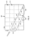
- the volume data set 200 is partitioned into 32 ⁇ 32 ⁇ 32 blocks of voxels 810 aligned with the major axes of the volume. Each block is represented by a 64-byte block of empty bits as described above.
- Section 330 passes through the volume array at an angle represented by view direction 220. The section intersects with blocks 811-821.
- the controller fetches the corresponding blocks of empty bits, ANDs the bits together and determines whether or not the corresponding blocks of voxels and samples can be skipped. Because sections are aligned with rays, transparent samples may be skipped without adding extra complexity to the circuitry of the present pipeline.
- controller 900 of the present pipelined rendering system operates as follows.
- the controller is provided with a complete rendering context 901.
- the rendering context includes all control information needed to render the volume, for example, the view direction, the size of the volume, equations defining cut and crop planes, bounding boxes, scaling factors, depth planes, etc.
- the controller uses the context to partition 910 the rays of the volume data set according to ray aligned sections 911.
- the sections 911 are enumerated for processing according to a predetermined order.
- Each section can be expressed in terms of its geometry with respect to its rays cast through the volume, and with respect to voxels needed to produce samples along the rays.
- step 920 For each section 911, step 920 performs visibility test 920 as described above. Sections that are outside the field of view (“invisible”) are skipped, and only "visible” sections 921 are further processed.
- Step 930 processes each visible section 921 from the perspective of voxels, and in parallel, step 940 processes the section from the perspective of samples.
- Step 930 steps along rays in slice order. For each slice, or group of slices, with look-ahead wherever possible, voxel visibility tests are performed as described above. If a particular slice has at least one visible voxel, then the controller issues a read slice command 931 to the memory interface 550, and a slice of voxels 420 is transferred from the memory 610 to one of the slice buffers 582 of the pipelines 540. If the slice fails the visibility test, then it is skipped.
- step 940 performs sample visibility tests. Note, that voxels and samples are arranged according different coordinate systems, therefore samples might fail this test, even though corresponding voxels passed, and vice versa. If the sample passes, then an interpolate sample command 941 is issued, along with interpolation weights (w) 560, and processing commences.
- the various stages of the pipeline perform further visibility tests, such early ray termination, and depth testing, and processing of a particular sample can be aborted.
- sample slices are partitioned into quadrants, with each quadrant being tested independently for visibility according to the cut plane, cropping, and depth tests.
Abstract
Description
- This invention relates generally to rendering volume data sets, and more particularly, the invention relates to pruning voxels and samples of volume data sets.
- Volume graphics is the subfield of computer graphics that deals with visualizing objects or models represented as sampled data in three or more dimensions, i.e., a volume data set. These data are called volume elements, or "voxels." The voxels store digital information representing physical characteristics of the objects or models being studied. For example, voxel values for a particular object or model may represent density, type of material, temperature, velocity, or some other property at discrete points in space throughout the interior and in the vicinity of that object or model.
- Volume rendering is that part of volume graphics concerned with the projection of the volume data set as two-dimensional images for purposes of printing, display on computer terminals, and other forms of visualization. By assigning color and transparency values to particular voxel data values, different views of the exterior and interior of an object or model can be rendered.
- For example, a surgeon needing to examine ligaments, tendons, and bones of a human knee in preparation for surgery can utilize a tomographic scan of the knee and cause voxel data values corresponding to blood, skin, and muscle to appear to be completely transparent. The resulting image then reveals the condition of the ligaments, tendons, bones, etc. which are hidden from view prior to surgery, thereby allowing for better surgical planning, shorter surgical operations, less surgical exploration and faster recoveries. In another example, a mechanic using a tomographic scan of a turbine blade or welded joint in a jet engine can cause voxel data values representing solid metal to appear to be transparent while causing those representing air to be opaque. This allows the viewing of internal flaws in the metal that otherwise is hidden from the human eye.
- Real-time volume rendering is the projection and display of the volume data set as a series of images in rapid succession, typically at thirty frames per second or faster. This makes it possible to create the appearance of moving pictures of the object, model, or system of interest. It also enables a human operator to interactively control the parameters of the projection and to manipulate the image, while providing to the user immediate visual feedback. Projecting hundreds of millions of voxel values to an image requires enormous amounts of computing power. Doing so in real time requires substantially more computational power.
- Further background on volume rendering is included in a Doctoral Dissertation entitled "Architectures for Real-Time Volume Rendering" submitted by Hanspeter Pfister to the Department of Computer Science at the State University of New York at Stony Brook in December 1996, and in U.S. Patent No. 5,594,842, "Apparatus and Method for Real-time Volume Visualization." Additional background on volume rendering is presented in a book entitled "Introduction to Volume Rendering" by Barthold Lichtenbelt, Randy Crane, and Shaz Naqvi, published in 1998 by Prentice Hall PTR of Upper Saddle River, New Jersey
- In one prior art volume rendering system, the rendering pipelines are configured as a single integrated chip, U.S. Patent Application Sn. 09/315,742 "Volume Rendering Integrated Circuit."
- In a method called "ray-casting," rays are cast through the volume data set, and sample points are calculated along each ray. Red, green, and blue color values, and an opacity value (also called alpha value) is determined for each sample point by interpolating voxels near the sample points. Collectively, the color and opacity values are called RGBA values. These RGBA values are typically composited along each ray to form a final pixel value, and the pixel values for all of the rays form a two-dimensional image of the three-dimensional object or model.
- In some systems based on the ray-casting method, one ray is cast through the volume array for each pixel in the image plane. In other systems, rays are cast according to a different spacing, then the final image is resampled to the pixel resolution of the image plane. In particular, the prior art systems cited above uses the well-known Shear-Warp algorithm of Lecroute et al. as described in "Fast Volume Rendering Using Shear-Warp Factorization of the Viewing Transform," Computer Graphics Proceedings of SIGGRAPH, pp. 451-457, 1994. There, rays are cast from uniformly spaced points on a plane parallel to one of the faces of the volume array. This plane is called the base plane, and the points are aligned with axes of the base plane.
- Figure 1 depicts a typical
volume rendering pipeline 100 of the prior art, such as described in US Patent Application Sn. 09/353,679 "Configurable Volume Rendering Pipeline." Voxels are read from avolume memory 110 and passed through agradient estimation stage 120 in order to estimate gradient vectors. The voxels and gradients are then passed throughinterpolation stages 130 in order to derive their values at sample points along rays, and throughclassification stages 140 in order to assign RGBA color and opacity values. The resulting RGBA values and interpolated gradients are then passed toillumination stages 150, where highlights and shadows are added. The values are then clipped and filtered instages 160 in order to remove portions of the volume or otherwise modulate the image of the volume. Finally, the values are composited instages 170 to accumulate all of the RGBA values for each ray into final pixel values for writing to apixel memory 180. - It should be noted that the
gradient estimation stages 120,interpolation stages 130, andclassification stages 140 can be connected in any order, depending upon the requirements of the application. This architecture is particularly suited to parallel implementation in a single integrated circuit, as described in the above referenced Patent Applications. - As an alternative to compositing a two-dimensional image, RGBA values can be written out as a three-dimensional array, thereby creating a new volume data set, which can be rendered with different transfer functions. In other words, the final images is the result of progressive rendering cycles on an evolving volume data set.
- One of the challenges in designing a volume rendering engine as a single semiconductor integrated circuit is to minimize the amount of on-chip memory required to support the functions of the volume rendering pipelines.
- As shown in Figure 2 for the shear-warp algorithm implemented of the prior art, the amount of on-chip memory is directly proportional to an area of a
face 210 of a volume data set 200 that is most nearly perpendicular to aview direction 220, that is the xy-face as illustrated in Figure 2. In the prior art, this memory was reduced by partitioning the volume into sections, and by rendering the volume a section at a time. - Figure 2 illustrates the partition of the volume into
sections 230 in both the x- and y-directions. Each section is defined by an area on the xy-face of the volume array and projects through the entire array in the z-direction. These sections are known as "axis-aligned sections" because they are parallel to the z-axis of the array. This partition reduces the requirement for on-chip memory to an amount proportional to the area of the face of the section in the xy-plane rather than to that of the entire volume. It also makes it possible to design a circuit capable of rendering arbitrarily large volume data sets with a fixed amount of on-chip memory. - One consequence of partitioning the volume data set into axis-aligned sections is that when rays traverse the volume at arbitrary angles, the rays cross from one section to another. For example, a
ray 240 parallel to viewdirection 220 enters intosection 231, crossessection 232, and then exits fromsection 233. Therefore, the volume rendering pipeline must save the partially composited (intermediate) values of rays that have been accumulated while traversing one section in an intermediate storage, so that those composited values are available when processing a subsequent section. Moreover, when a volume rendering system comprises a number of pipelines operating in parallel, the values of the rays must be passed from one pipeline to the next, even within a particular section. - These two requirements cause the need for a considerable amount of circuitry to communicate data among the pipelines and to write and read intermediate ray values. It is desirable to reduce this communication and circuit complexity.
- It is common in volume rendering applications to specify portions of the volume data set that are cut away or clipped, so that interior portions of the object can be viewed, see U.S. Patent Application Sn. 09/190,645. For example, cut planes can be used to slice through the volume array at any oblique angle, showing an angled cross-section of the object. Similarly, combinations of crop planes may be employed to provide distinctive views of an object.
- Another method of clipping a volume is by an arbitrary clip surface represented by a depth buffer, see U.S. Patent Application Sn. 09/219,059. Depth tests associated with the depth buffer can be used to include or exclude sample points based on their depth values relative to the depth buffer.
- In a prior art pipeline, such as represented by Figure 1, tests for clipping and cropping were implemented in
stages 160 just prior to thecompositor 170. Depth tests were implemented in thecompositor 170 itself. The effect was that every voxel of the volume data set was read into thepipeline 100, and every sample was processed through most, if not all of the volume rendering pipeline, whether or not the sample contributed to the final image of the object or model being rendered. In most cases, this represents unnecessary processing and inefficient use of circuitry. It is desirable to skip over voxels and samples completely if those voxels do not contribute to the final image. - There are three ways that a sample point may not be visible in the final image. First, the sample may be clipped out of the final image by one of the cut planes, crop planes, or depth tests. Second, the sample may be obscured by other samples which are individually or collectively opaque. Third, the sample may have been assigned a transparent color while the sample is processed.
- Skipping over voxels or samples that are explicitly clipped is called "pruning." While this is easy in software implementations of volume rendering, pruning is difficult in hardware implementations. The reason is that prior art hardware systems focus on the systematic movement of data in order to obtain the desired performance from conventional dynamic random access memory (DRAM) modules. By skipping over such data, the orderly progression of data from voxel memory through the volume rendering pipelines is upset, and a complex amount of control information is necessary to keep track of samples and their data.
- Skipping samples that are obscured by other parts of the volume is called "early ray termination." Again, this is easy in software implementations, but very difficult in hardware implementations. Skipping some rays and not others also upsets the orderly progression of data flowing from the memory through the pipelines, just as in the case of pruning voxels and samples.
- One form of early ray termination is described by Knittel in "TriangleCaster - Extensions to 3D-Texture Units for Accelerated Volume Rendering," Proceedings of Eurographics SIGGRAPH, pp. 25-34, 1999. There, volumes are rendered by passing a series of triangles through a 3D texture map in a front-to-back order. If all of the pixels of a triangle are opaque, then triangles behind that triangle can be skipped. The difficulty with that method is that the method depends on first converting the volume to triangles, rather than rendering the volume directly. Moreover, that method cannot terminate opaque rays on a ray-by-ray basis, only on a triangle-to-triangle basis.
- Skipping over transparent parts of the volume is called "space leaping." This is commonly practiced in software volume rendering systems, but space leaping requires that the volume data set is pre-processed each time transfer functions assigning RGBA values change. This pre-processing step is costly in performance, but the result is a net benefit when the transfer functions do not change very often. In prior art hardware systems, space leaping also required a pre-processing step, but at hardware speeds. However, taking advantage of space-leaping upsets the ordered progression of data flowing from the memory through the pipelines, just as pruning voxels and samples and just as early ray termination.
- In Knittel's TriangleCaster system, space leaping is accomplished by first encapsulating non-transparent portions of the volume with a convex polyhedral hull formed of triangles. Portions of the volume outside the hull are excluded by using depth tests on the hull. As a problem, that method requires a significant amount of processing on the host system which must be repeated whenever the transfer function changes, possible making that method unsuitable for real-time interactive volume rendering. As another problem, an object with large concavities, such as a turbine with razor thin blades, will mostly consist of transparent portions within the convex hull. It would be desirable to use the rendering engine itself for space leaping.
- Therefore, it is desirable to have a hardware volume rendering architecture that operates with real-time performance but does not have to render voxels and samples that are clipped out of the image, that are obscured by other parts of the image, or that are transparent.
- A method renders a volume data set as an image in a volume rendering system. The volume data set includes a plurality of voxels stored in a memory. The volume rendering system includes a plurality of parallel processing pipelines.
- The image includes a plurality of pixels stored in an image buffer. A determination is made whether a particular voxel of the volume data set will contribute to the image. The voxel is read into one of the plurality of pipelines only if the particular voxel contributes to a particular pixel of the image.
-
- Figure 1 is a block diagram of a prior art volume rendering pipeline;
- Figure 2 is a diagram of a volume data set partitioned into axis-aligned sections of the prior art;
- Figure 3 is a diagram of a volume data set partitioned into ray-aligned sections;
- Figure 4 is a cross-sectional view of a ray-aligned section;
- Figure 5 is a block diagram of volume rendering pipelines according to the invention;
- Figure 6 is a diagram of a three-dimensional array of empty bits corresponding to the volume data set;
- Figure 7 is a block diagram of one empty bit for a block of the volume data set;
- Figure 8 is a cross-section of the volume data set; and
- Figure 9 is a flow diagram of a controller for the rendering pipelines of Figure 5.
-
- As shown in Figure 3, the present volume rendering system partitions the
volume data set 200 into ray-aligned sections 330-332. Each section is defined by anarea 340 on an xy-face 210 of avolume data set 200. The sections project through the volume in a direction parallel to a selectedview direction 220 rather than parallel to the z-axis as in the prior art. Each ray-aligned section is defined as a "bundle" or set of rays, rather than a set of voxels as in the prior art. - Each ray-aligned section encompasses all of sample points needed to produce a final RGBA pixel values for each ray of the section's ray set.
- In the preferred embodiment, the pattern of the rays defining the bundle is typically a rectangle or parallelogram on the xy-
face 210 of thevolume data set 200. However, other patterns can also be chosen. For example,section 330 is the subset of rays parallel to theview direction 220 that strike therectangular area 340 of the face of the volume array, then proceed through the volume in an increasing x- and y-direction. - Figure 4 is a cross-sectional view of the
volume data set 200 in the yz-plane with a side view ofsection 330. Slices are two-dimensional arrays of voxels parallel to the xy-face of the volume array. These are depicted in Figure 4 as vertical columns of "x" symbols 410, 412, 414, etc. The second dimension of each slice is perpendicular to the page. Planes ofsamples - In contrast to the prior art, the present rendering system offsets each voxel slice from the previous voxel slice by an amount determined by the angle of the ray for a particular view direction. For example, section slices 420, 422, and 424 are subsets respectively of slices 410, 412, and 414 needed to render
section 330. Note thatsection slice 422 is offset in the y-direction fromsection slice 420 and thatsection slice 424 is offset in the y-direction fromsection slice 422. In general, a section slice may be offset in both the x- and y-directions from its neighbor. - Note that interpolation of sample values and estimation of gradients of samples near the edge of the section depend upon voxels that lie near the edges in adjacent sections. Therefore, near the edges, the voxels of the sections partially overlap. The amount of overlap is determined by the size of the convolution kernel needed for estimating gradients and interpolating the samples from the voxels.
- Ray-aligned sections bring a number of advantages. For example, the samples of an entire ray may be assigned to a particular volume rendering pipeline, as described below. As a result, no intermediate values need to be passed among adjacent pipelines. Because each ray is contained entirely within one section, no intermediate values of rays need be communicated from one section to another via on-chip or off-chip memory. Both of these result in considerable reductions in the amount of circuitry needed in the volume rendering pipelines.
- Other advantages of ray-aligned sections include the ability of the pipeline to efficiently compare sample positions to depth buffers produced by a traditional graphics engine. This in turn enables both arbitrary volume clipping and embedding polygon graphics into the rendered volume. Ray-aligned sections also allow a variety of optimizations, such as space leaping and early ray termination described in greater detail below.
- Figure 5 is a block diagram of an
integrated circuit 500 and associatedmemory modules 510 for rendering a volume data set partitioned into ray-aligned sections according to the present rendering system. - The
integrated circuit 500 includes amemory interface 520, apipeline controller 900, and a plurality of volume rendering pipelines 540a, ..., 540d. Not shown in Figure 5, but necessary in a practical system, is a bus interface for communication with a host computer. A user interacts with the host while rendering the volume data set stored in thememory 510. - The
integrated circuit 500 acts as a special purpose SIMD (Single-Instruction, Multiple Data) parallel processor, with thecontroller 900 providing control logic and the volume rendering pipelines 540a, ..., 540d comprising the execution engines operating in response to controller commands. Each of the pipelines also includes numerous registers and buffers for storing data and control information during operation. - Each pipeline 540a-d includes a slice buffer 582 at a first stage of the pipeline, a gradient estimation unit 584, interpolation stages 586, classification stages 588, illumination stages 590, filter stages 592, depth test, composite and early ray termination (ERT) stages 594, and depth and image buffers 596 at a last stage of the pipeline.
- During operation of the pipelines, the
controller 900 performs a number of functions. The controller partitions the volume according to the ray-aligned sections of Figure 3, and processes data associated with the ray-aligned sections in a predetermined order. The controller issues memory access commands to thememory interface 550. The commands transfer data between thememory 510 and the pipelines 540a-d. For example, the controller issues read commands to the interface to distribute slices of voxels from thememory 510 to the slice buffers. The controller initializes the depth buffers 596, and the controller writes pixel values back to thememory 510. - The controller also generates the
weights 560 used by the convolution kernels. The convolution kernels are used during gradient estimation and interpolation. At the completion of each section, the controller issues commands to write images to the memory, and to updated depth buffers as necessary. - For each section, depth and image buffers are both read and written in order to allow embedding of polygon objects within images of volume objects. While reading depth buffers for a section, minimum and maximum (Min, Max) values 570 are obtained for use by
controller 900 in voxel pruning described below. - The
controller 900 assigns the rays of a section equally among the plurality of pipelines 540a, ..., 540d. When the controller initializes the depth and image buffers in preparation a section to be processed, the controller partitions section's data among the depth andimage buffers 596a, ..., 596d according to the partitioning of the rays. For example, in the preferred embodiment, there are four volume rendering pipelines inintegrated circuit 500, so that each depth andimage buffer 596a, ..., 596d holds one fourth of the total depth and image values for the section. - When the
controller 900 causes voxels of a slice to be fetched, the controller directs them to theslice buffers 582a, ..., 582d so that each pipeline has the necessary voxels to render its rays. In this case, a voxel will typically be directed to more than one slice buffer because a particular voxel may be needed for interpolating samples of multiple rays. - In each clock cycle, a particular pipeline takes voxels needed for gradient estimation and interpolation of one sample point from its slice buffer 582. This sample point then passes down the pipeline, one stage per cycle, until it is composited into the image buffer 596 at the last stage of the pipeline.
- In pipeline fashion, the
controller 900 causes a stream of voxels from all the section slices of a section to be directed to theslice buffers 582a, ..., 582d, fast enough for the pipelines 540a, ..., 540d to process the voxels and composite samples into the image buffer 596. - Even though each section slice is offset from its neighboring slice, the controller aligns the section slices so that sample points for each ray are always processed by the same pipeline. Therefore, unlike the prior art, communication among adjacent pipelines is avoided. This results in a considerable simplification of the
integrated circuit 500. - The relative position of the slice buffers 582 and the gradient estimation stage 584 may be interchanged in order to reduce the amount of redundant on-chip memory devoted to the slice buffers. For example, gradients can be estimated before the voxels are stored in the slice buffers.
- Supersampling in the x- and y-directions becomes trivial with ray-aligned sections because the
controller 900 focuses on rays, not voxels. If rays are spaced closer than voxels in either the x- or the - or the y-direction to achieve supersampling, then appropriate voxels can be directed redundantly to the pipelines responsible for the respective rays. In contrast, voxels in prior art pipelines were associated with pipelines, not rays, and therefore considerable communication among pipelines and other complexity were required for supersampling, see for example, U.S. Patent Application 09/190,712 - In the present pipelined volume rendering system, one goal is to minimize the number of voxels and samples that need to be processed, thereby improving performance. Therefore, numerous steps are taken to identify these data. Furthermore, another goal is to identify such data as early as possible. The identification of "visible" and "invisible" data is done both by the controller and the various stages of the pipelines.
- For example, as the controller enumerates sections, cut plane equations are tested, and cropping boundaries are checked to determine whether particular samples of a section are included or excluded from the view. If the samples are excluded from the view, then the processing of the section can be terminated without reading voxels and without sending samples down the volume rendering pipelines. Furthermore, the controller "looks-ahead" to anticipate whether later processed data can cause current data to become invisible, in which case processing of current data can be skipped altogether.
- Likewise, the controller performs coarse grain depth tests for each section. The controller does this by determining the minimum and
maximum values 570 of each depth array as the array is fetched from memory into the image anddepth buffers 596a, ..., 596d. These minimum andmaximum values 570 are communicated to thecontroller 900 from the depth and image buffers 596. If the controller can determine that all of the depth tests of all of the samples within a section fail, then processing of that section can be terminated without reading voxels and without sending samples down the pipelines. - The controller repeats these tests at a finer grain as described below. For example, if the controller can be determined that all of the samples of a particular slice or group of slices fail a clip, crop, or depth test, then those slices are skipped.
- Because sections in the present pipelined volume rendering system are ray aligned, the skipping of samples, slices, or whole sections presents no problem for the pipelines 540a, ..., 540d. Each pipeline processes an independent set of rays and each sample point passes down the pipeline independent of samples in other pipelines. It is only necessary to include "visibility" control information for each sample as the sample flows down the pipeline, so that the sample is composited with the correct element of the final image buffer. If sections were aligned with the z-axis of the volume, then this control information would entail great complexity.
- Therefore, each sample has an associated "visibility" bit. As long as the visibility bit is set, the sample is valid for processing. When it is determined that the sample will not contribute to the final image, that is the bit is unset, and the sample becomes invalid for further processing.
- Note that for samples that are passed down the pipelines, a final depth test must still be performed because the depth buffer value associated with that ray may lie somewhere between the minimum and maximum of the section. This final depth test is performed during compositing, in
stage 594a, ..., 594d. - Early ray termination is an optimization that recognizes when further samples along a ray cannot affect the final composited result. For example, during front-to-back processing, when a fully opaque surface is encountered, no samples behind the surface will be visible, and hence these samples need not be processed. Similarly, when rays pass through thick translucent material such as fog, they may eventually accumulate so much opacity that no samples further along the ray can be seen. In another example, the depth values of a ray may cross a threshold so that no further samples along that ray pass depth tests.
- In these cases, the compositor 594 may determine that processing of the ray can be terminated. In this case, the compositer signals the controller to stop processing that ray via an ERT (Early Ray Termination) signals 572. When the controller receives such the ERT signal for a ray, it skips over subsequent voxels and samples involving that ray. The controller also keeps track of the ERT signals for all of the rays of a section, so that when all rays in a particular section are terminated, processing for the entire section is terminated.
- In a typical implementation, the controller maintains a bit mask. The mask has one bit for each ray of the section. When all of the bits of the mask indicate termination, then the section is terminated.
- Note that in most cases, when the compositor has determined that a ray should be terminated, there may still be samples for that ray in previous stages of the volume rendering pipeline. Therefore, in order to preserve the semantics of early ray termination, the compositer ignores and discards all subsequent samples along that ray after the compositor has determined that a ray has terminated according to any criterion. Thus, there will be a delay between the time of early termination of one ray and the last sample of that ray to complete its course through the pipeline.
- In the preferred embodiment, the threshold of opacity for early ray termination is implemented in a register that can be set by an application program. Therefore, any level of opacity may be used to terminate rays, even if the human eye were capable of detecting objects behind the terminated sample.
- Space leaping allows the pipelines to skip over transparent portions of the volume. For example, many volume models include one or more portions of transparent "empty" space around the object or model of interest. Also, classification and lighting functions may make certain types of tissue or material transparent. Similarly, filtering functions based on modulation of gradient magnitudes can cause portions of the volume to become transparent. By skipping these transparent portions, the number of invisible samples is reduced, thereby reducing the time needed to render the entire volume.
- As shown in Figures 6 and 7, the present pipelined volume rendering system implements space leaping by maintaining an array of
bits 620 called "empty bits" corresponding to thevolume array 610. For the threedimensional volume array 610, there is a corresponding three dimensional array ofempty bits 620. Typically, onebit 720 in the array of empty bits corresponds to a block ofvoxels 710. If theempty bit 720 is set, then the voxels of thecorresponding block 710 will not contribute to the visibility of samples passing near them. That is, the volume at each of the voxels in the block is transparent. - As shown in Figure 7, each
empty bit 720 can correspond to a cubic block of, for example, 4×4×4 voxels, or 64 voxels in total. The 4×4×4 cubic array ofvoxels 710 is represented by the singleempty bit 720. Therefore, the empty bit array has 1/64th the number of bits as there are voxels. Because voxels may be 8, 16, 32, or more bits, the empty bit array requires 1/512th, 1/1024th, 1/12048th, or a smaller fraction of the storage of the volume array itself. - The semantics of empty bits are as follows. If all of the voxels needed to interpolate a sample point are indicated as transparent by their empty bits, then the sample point itself is deemed to be invisible and not contributing to the final image. Therefore, the
controller 900 can omit the reading of those voxels, and can avoid sending the sample points down the volume rendering pipeline. - If, as is typical in many volume data sets, a large portion of a volume is transparent as indicated by their empty bits, then the controller can omit reading those voxels and processing those samples. By simply ANDing together the empty bits of a region, the controller can efficiently skip the region.
- In the preferred embodiment, the array of
empty bits 620 is generated by the pipelines themselves, operating in a special mode, in other words, there is no lengthy preprocessing by the host. In this mode, the view direction is aligned with one of the major axes of the volume, and the sample points are set to be exactly aligned with voxel positions, hence interpolation becomes trivial. - Then, the volume is rendered once with desired transfer functions to assign color and opacity and with desired filters based on gradient magnitude and other factors. The compositing stages 594a, ..., 594d examine each RGBA sample to determine whether the opacity of the sample is less than a predetermined threshold. If true, then the sample and its corresponding voxel are deemed to be transparent. If all of the voxels in a 4×4×4 region are transparent, then the corresponding empty bit is set to true. If, however, any voxel in the region is not transparent, then the corresponding empty bit is set to false.
- During normal rendering of a volume data set, the
controller 900 reads a array of empty bits for the parts of the volume through which a particular section passes. If all of the bits indicate that the portion of the volume is transparent, then the slices of voxels in that portion of the volume are not read and the samples based on these slices are not processed. - This is illustrated in Figure 8. For the purpose of the empty bits, the
volume data set 200 is partitioned into 32×32×32 blocks ofvoxels 810 aligned with the major axes of the volume. Each block is represented by a 64-byte block of empty bits as described above.Section 330 passes through the volume array at an angle represented byview direction 220. The section intersects with blocks 811-821. As part of processing thesection 330, the controller fetches the corresponding blocks of empty bits, ANDs the bits together and determines whether or not the corresponding blocks of voxels and samples can be skipped. Because sections are aligned with rays, transparent samples may be skipped without adding extra complexity to the circuitry of the present pipeline. - Naturally, if classification lookup tables assigning color and opacity change, or if filter functions affecting modulation of opacity change, then the
empty bit array 620 becomes invalid, and must be recomputed. However, this does not require host processor resources. - As illustrated by Figure 9, the
controller 900 of the present pipelined rendering system operates as follows. - The controller is provided with a
complete rendering context 901. The rendering context includes all control information needed to render the volume, for example, the view direction, the size of the volume, equations defining cut and crop planes, bounding boxes, scaling factors, depth planes, etc. - The controller uses the context to partition 910 the rays of the volume data set according to ray aligned
sections 911. Thesections 911 are enumerated for processing according to a predetermined order. Each section can be expressed in terms of its geometry with respect to its rays cast through the volume, and with respect to voxels needed to produce samples along the rays. - For each
section 911,step 920 performsvisibility test 920 as described above. Sections that are outside the field of view ("invisible") are skipped, and only "visible"sections 921 are further processed. - Step 930 processes each
visible section 921 from the perspective of voxels, and in parallel, step 940 processes the section from the perspective of samples. - Step 930 steps along rays in slice order. For each slice, or group of slices, with look-ahead wherever possible, voxel visibility tests are performed as described above. If a particular slice has at least one visible voxel, then the controller issues a
read slice command 931 to thememory interface 550, and a slice ofvoxels 420 is transferred from thememory 610 to one of the slice buffers 582 of the pipelines 540. If the slice fails the visibility test, then it is skipped. - Concurrently,
step 940 performs sample visibility tests. Note, that voxels and samples are arranged according different coordinate systems, therefore samples might fail this test, even though corresponding voxels passed, and vice versa. If the sample passes, then aninterpolate sample command 941 is issued, along with interpolation weights (w) 560, and processing commences. - Subsequently, the various stages of the pipeline perform further visibility tests, such early ray termination, and depth testing, and processing of a particular sample can be aborted.
- It will be appreciated that additional optimizations for further improvements in volume rendering performance. For example, in certain embodiments, sample slices are partitioned into quadrants, with each quadrant being tested independently for visibility according to the cut plane, cropping, and depth tests.
Claims (3)
- A method for rendering a volume data set as an image in a volume rendering system, wherein the volume data set includes a plurality of voxels stored in a memory, the volume rendering system includes a plurality of parallel processing pipelines, and the image includes a plurality of pixels stored in an image buffer; comprising the steps of:determining whether a particular voxel of the volume data set will contribute to the image; andreading the voxel into one of the plurality of pipelines only if the particular voxel contributes to a particular pixel of the image.
- The method of claim 1 wherein a sample interpolated from the voxels is tested against minimum and maximum depth values stored in depth buffers at a last stage of the plurality of parallel processing pipelines.
- The method of claim 1 further comprising the steps of:determining whether a particular sample interpolated from the voxels will contribute to the image; andinterpolating voxels associated with the sample only of the particular sample contributes to the image.
Applications Claiming Priority (2)
| Application Number | Priority Date | Filing Date | Title |
|---|---|---|---|
| US09/410,770 US20020190984A1 (en) | 1999-10-01 | 1999-10-01 | Voxel and sample pruning in a parallel pipelined volume rendering system |
| US410770 | 1999-10-01 |
Publications (2)
| Publication Number | Publication Date |
|---|---|
| EP1089234A2 true EP1089234A2 (en) | 2001-04-04 |
| EP1089234A3 EP1089234A3 (en) | 2004-01-02 |
Family
ID=23626141
Family Applications (1)
| Application Number | Title | Priority Date | Filing Date |
|---|---|---|---|
| EP00120074A Withdrawn EP1089234A3 (en) | 1999-10-01 | 2000-09-15 | Parallel pipelined volume rendering system |
Country Status (3)
| Country | Link |
|---|---|
| US (1) | US20020190984A1 (en) |
| EP (1) | EP1089234A3 (en) |
| JP (1) | JP2001109903A (en) |
Cited By (2)
| Publication number | Priority date | Publication date | Assignee | Title |
|---|---|---|---|---|
| USRE42952E1 (en) | 1999-11-05 | 2011-11-22 | Vital Images, Inc. | Teleradiology systems for rendering and visualizing remotely-located volume data sets |
| CN113140027A (en) * | 2020-01-16 | 2021-07-20 | 浙江碧晟环境科技有限公司 | Construction method of four-dimensional water body model |
Families Citing this family (28)
| Publication number | Priority date | Publication date | Assignee | Title |
|---|---|---|---|---|
| US7154500B2 (en) * | 2004-04-20 | 2006-12-26 | The Chinese University Of Hong Kong | Block-based fragment filtration with feasible multi-GPU acceleration for real-time volume rendering on conventional personal computer |
| US7339586B2 (en) * | 2004-04-23 | 2008-03-04 | Siemens Medical Solutions Usa, Inc. | Method and system for mesh-to-image registration using raycasting |
| US7298372B2 (en) * | 2004-10-08 | 2007-11-20 | Mitsubishi Electric Research Laboratories, Inc. | Sample rate adaptive filtering for volume rendering |
| US7970625B2 (en) | 2004-11-04 | 2011-06-28 | Dr Systems, Inc. | Systems and methods for retrieval of medical data |
| US7787672B2 (en) | 2004-11-04 | 2010-08-31 | Dr Systems, Inc. | Systems and methods for matching, naming, and displaying medical images |
| US7920152B2 (en) | 2004-11-04 | 2011-04-05 | Dr Systems, Inc. | Systems and methods for viewing medical 3D imaging volumes |
| US7660488B2 (en) | 2004-11-04 | 2010-02-09 | Dr Systems, Inc. | Systems and methods for viewing medical images |
| US7885440B2 (en) | 2004-11-04 | 2011-02-08 | Dr Systems, Inc. | Systems and methods for interleaving series of medical images |
| US7711162B2 (en) * | 2005-01-27 | 2010-05-04 | Siemens Medical Solutions Usa, Inc. | Accelerated texture-based fusion renderer |
| US7460119B2 (en) * | 2005-01-27 | 2008-12-02 | Siemens Medical Solutions Usa, Inc. | Invisible space skipping with adaptive granularity for texture-based volume rendering |
| US7692651B2 (en) * | 2005-09-22 | 2010-04-06 | Siemens Medical Solutions Usa, Inc. | Method and apparatus for providing efficient space leaping using a neighbor guided emptiness map in octree traversal for a fast ray casting algorithm |
| US20070132754A1 (en) * | 2005-12-12 | 2007-06-14 | Intel Corporation | Method and apparatus for binary image classification and segmentation |
| US8031208B2 (en) * | 2005-12-26 | 2011-10-04 | Kabushiki Kaisha Toshiba | Drawing apparatus and method for processing plural pixels in parallel |
| US20080024494A1 (en) * | 2006-07-25 | 2008-01-31 | Perumal Poopathy | Method and system for image based rendering large volumetric datasets |
| US7953614B1 (en) | 2006-11-22 | 2011-05-31 | Dr Systems, Inc. | Smart placement rules |
| DE102007008767B3 (en) * | 2007-02-22 | 2008-07-24 | Tomtec Imaging Systems Gmbh | Method for representation of three-dimensional graphic data sets on two-dimensional images, involves initializing three-dimensional data set of three-dimensional image volume and arranging line of sight to produce two-dimensional image |
| US20080232694A1 (en) * | 2007-03-21 | 2008-09-25 | Peter Sulatycke | Fast imaging data classification method and apparatus |
| US8380533B2 (en) | 2008-11-19 | 2013-02-19 | DR Systems Inc. | System and method of providing dynamic and customizable medical examination forms |
| US8712120B1 (en) | 2009-09-28 | 2014-04-29 | Dr Systems, Inc. | Rules-based approach to transferring and/or viewing medical images |
| US9092551B1 (en) | 2011-08-11 | 2015-07-28 | D.R. Systems, Inc. | Dynamic montage reconstruction |
| US9495604B1 (en) | 2013-01-09 | 2016-11-15 | D.R. Systems, Inc. | Intelligent management of computerized advanced processing |
| GB201415534D0 (en) * | 2014-09-02 | 2014-10-15 | Bergen Teknologioverforing As | Method and apparatus for processing three-dimensional image data |
| US9865080B2 (en) * | 2014-09-11 | 2018-01-09 | Siemens Medical Solutions Usa, Inc. | Velocity volume rendering with sign-based termination in ultrasound |
| US9934602B2 (en) * | 2015-03-12 | 2018-04-03 | Happy L-Lord AB | System, method and device for three-dimensional modeling |
| US9852526B2 (en) * | 2015-04-10 | 2017-12-26 | Toshiba Medical Systems Corporation | Method and apparatus of resampling and averaging to obtain tilted thick-slice computed tomography images |
| US20170046483A1 (en) | 2015-04-30 | 2017-02-16 | D.R. Systems, Inc. | Database systems and interactive user interfaces for dynamic interaction with, and comparison of, digital medical image data |
| KR102384304B1 (en) * | 2019-07-15 | 2022-04-07 | 레고 에이/에스 | Rendering method and rendering device performing the same |
| US11398072B1 (en) * | 2019-12-16 | 2022-07-26 | Siemens Healthcare Gmbh | Method of obtaining a set of values for a respective set of parameters for use in a physically based path tracing process and a method of rendering using a physically based path tracing process |
Citations (1)
| Publication number | Priority date | Publication date | Assignee | Title |
|---|---|---|---|---|
| GB2325835A (en) * | 1997-05-30 | 1998-12-02 | Hewlett Packard Co | Volumetric pre-clipping method in a volumetric rendering system |
Family Cites Families (4)
| Publication number | Priority date | Publication date | Assignee | Title |
|---|---|---|---|---|
| US5377313A (en) * | 1992-01-29 | 1994-12-27 | International Business Machines Corporation | Computer graphics display method and system with shadow generation |
| JPH0636048A (en) * | 1992-07-13 | 1994-02-10 | Toshiba Corp | Volume data clipping system |
| KR100261077B1 (en) * | 1996-04-25 | 2000-07-01 | 윤종용 | Volume rendering apparatus and method therefor |
| JPH11203501A (en) * | 1998-01-14 | 1999-07-30 | Sega Enterp Ltd | Picture processor and picture processing method |
-
1999
- 1999-10-01 US US09/410,770 patent/US20020190984A1/en not_active Abandoned
-
2000
- 2000-09-07 JP JP2000270910A patent/JP2001109903A/en active Pending
- 2000-09-15 EP EP00120074A patent/EP1089234A3/en not_active Withdrawn
Patent Citations (1)
| Publication number | Priority date | Publication date | Assignee | Title |
|---|---|---|---|---|
| GB2325835A (en) * | 1997-05-30 | 1998-12-02 | Hewlett Packard Co | Volumetric pre-clipping method in a volumetric rendering system |
Non-Patent Citations (3)
| Title |
|---|
| SOMMER O ET AL: "An interactive visualization and navigation tool for medical volume data" COMPUTERS AND GRAPHICS, PERGAMON PRESS LTD. OXFORD, GB, vol. 23, no. 2, April 1999 (1999-04), pages 233-244, XP004165787 ISSN: 0097-8493 * |
| SRAMEK M: "Fast surface rendering from raster data by voxel traversal using chessboard distance" VISUALIZATION, 1994., VISUALIZATION '94, PROCEEDINGS., IEEE CONFERENCE ON WASHINGTON, DC, USA 17-21 OCT. 1994, LOS ALAMITOS, CA, USA,IEEE COMPUT. SOC, 17 October 1994 (1994-10-17), pages 188-195,CP21, XP010100568 ISBN: 0-8186-6627-7 * |
| YACOOB Y: "Displaying voxel-based objects according to their qualitative shape synthesis" PROCEEDINGS OF THE CONFERENCE ON VISUALIZATION. SAN FRANCISCO, OCT. 23 - 26, 1990, LOS ALAMITOS, IEEE COMP. SOC. PRESS, US, vol. CONF. 1, 23 October 1990 (1990-10-23), pages 51-58,463-4, XP010021060 ISBN: 0-8186-2083-8 * |
Cited By (4)
| Publication number | Priority date | Publication date | Assignee | Title |
|---|---|---|---|---|
| USRE42952E1 (en) | 1999-11-05 | 2011-11-22 | Vital Images, Inc. | Teleradiology systems for rendering and visualizing remotely-located volume data sets |
| USRE44336E1 (en) | 1999-11-05 | 2013-07-02 | Vital Images, Inc. | Teleradiology systems for rendering and visualizing remotely-located volume data sets |
| CN113140027A (en) * | 2020-01-16 | 2021-07-20 | 浙江碧晟环境科技有限公司 | Construction method of four-dimensional water body model |
| CN113140027B (en) * | 2020-01-16 | 2022-07-15 | 浙江碧晟环境科技有限公司 | Construction method of four-dimensional water body model |
Also Published As
| Publication number | Publication date |
|---|---|
| JP2001109903A (en) | 2001-04-20 |
| EP1089234A3 (en) | 2004-01-02 |
| US20020190984A1 (en) | 2002-12-19 |
Similar Documents
| Publication | Publication Date | Title |
|---|---|---|
| US6654012B1 (en) | Early ray termination in a parallel pipelined volume rendering system | |
| EP1089234A2 (en) | Parallel pipelined volume rendering system | |
| EP1014308B1 (en) | Method and apparatus for volume rendering with multiple depth buffers | |
| TWI448983B (en) | Method and system for rendering 3d model of 3d object | |
| JP4158167B2 (en) | Volume graphics device | |
| US8284197B2 (en) | Method and apparatus for rendering instance geometry | |
| US6424345B1 (en) | Binsorter triangle insertion optimization | |
| US20080231632A1 (en) | Accelerated volume image rendering pipeline method and apparatus | |
| JP2000348202A (en) | Shifting warp renderling method for volume data set having voxel and rendering method for volume data set | |
| US7812837B2 (en) | Reduced Z-buffer generating method, hidden surface removal method and occlusion culling method | |
| US20070268291A1 (en) | Occlusion Culling Method and Rendering Processing Apparatus | |
| JPH07152926A (en) | Method for shading of three-dimensional image | |
| US20050140684A1 (en) | Graphical data access method apparatus and system | |
| JP2000357240A (en) | Volume rendering device, volume graphic integrated circuit, and volume rendering integrating circuit | |
| US20150049110A1 (en) | Rendering using multiple render target sample masks | |
| WO2002001500A2 (en) | Method, apparatus and article for determining visible parts of surfaces of three-dimensional objects and their parameters of shading accounting for light and shadow volumes | |
| Meißner et al. | Volume Visualization and Volume Rendering Techniques. | |
| EP1093085B1 (en) | Parallel pipelined volume rendering system | |
| US11341708B2 (en) | Graphics processing | |
| EP1089235A2 (en) | Space leaping in a parallel pipelined volume rendering system | |
| EP1209629A1 (en) | Early ray termination in a parallel pipelined volume rendering system | |
| EP1089225A2 (en) | Parallel pipelined volume rendering system | |
| JP2002183746A (en) | Rendering method for volume data set | |
| US8179394B1 (en) | Cull streams for fine-grained rendering predication | |
| US9489767B1 (en) | Cull streams for fine-grained rendering predication |
Legal Events
| Date | Code | Title | Description |
|---|---|---|---|
| PUAI | Public reference made under article 153(3) epc to a published international application that has entered the european phase |
Free format text: ORIGINAL CODE: 0009012 |
|
| AK | Designated contracting states |
Kind code of ref document: A2 Designated state(s): AT BE CH CY DE DK ES FI FR GB GR IE IT LI LU MC NL PT SE |
|
| AX | Request for extension of the european patent |
Free format text: AL;LT;LV;MK;RO;SI |
|
| RAP1 | Party data changed (applicant data changed or rights of an application transferred) |
Owner name: TERARECON, INC., A DELAWARE CORPORATION |
|
| PUAL | Search report despatched |
Free format text: ORIGINAL CODE: 0009013 |
|
| AK | Designated contracting states |
Kind code of ref document: A3 Designated state(s): AT BE CH CY DE DK ES FI FR GB GR IE IT LI LU MC NL PT SE |
|
| AX | Request for extension of the european patent |
Extension state: AL LT LV MK RO SI |
|
| RIC1 | Information provided on ipc code assigned before grant |
Ipc: 7G 06T 15/10 A Ipc: 7G 06T 15/00 B |
|
| STAA | Information on the status of an ep patent application or granted ep patent |
Free format text: STATUS: THE APPLICATION IS DEEMED TO BE WITHDRAWN |
|
| AKX | Designation fees paid | ||
| 18D | Application deemed to be withdrawn |
Effective date: 20040401 |
|
| REG | Reference to a national code |
Ref country code: DE Ref legal event code: 8566 |