EP1074718A2 - Method for testing plausibility of engine and probe parameters using a wide range lambda sensor - Google Patents
Method for testing plausibility of engine and probe parameters using a wide range lambda sensor Download PDFInfo
- Publication number
- EP1074718A2 EP1074718A2 EP00115537A EP00115537A EP1074718A2 EP 1074718 A2 EP1074718 A2 EP 1074718A2 EP 00115537 A EP00115537 A EP 00115537A EP 00115537 A EP00115537 A EP 00115537A EP 1074718 A2 EP1074718 A2 EP 1074718A2
- Authority
- EP
- European Patent Office
- Prior art keywords
- internal combustion
- combustion engine
- lambda probe
- control value
- lambda
- Prior art date
- Legal status (The legal status is an assumption and is not a legal conclusion. Google has not performed a legal analysis and makes no representation as to the accuracy of the status listed.)
- Granted
Links
Images
Classifications
-
- F—MECHANICAL ENGINEERING; LIGHTING; HEATING; WEAPONS; BLASTING
- F02—COMBUSTION ENGINES; HOT-GAS OR COMBUSTION-PRODUCT ENGINE PLANTS
- F02D—CONTROLLING COMBUSTION ENGINES
- F02D41/00—Electrical control of supply of combustible mixture or its constituents
- F02D41/02—Circuit arrangements for generating control signals
- F02D41/14—Introducing closed-loop corrections
- F02D41/1438—Introducing closed-loop corrections using means for determining characteristics of the combustion gases; Sensors therefor
- F02D41/1493—Details
- F02D41/1495—Detection of abnormalities in the air/fuel ratio feedback system
-
- F—MECHANICAL ENGINEERING; LIGHTING; HEATING; WEAPONS; BLASTING
- F02—COMBUSTION ENGINES; HOT-GAS OR COMBUSTION-PRODUCT ENGINE PLANTS
- F02D—CONTROLLING COMBUSTION ENGINES
- F02D41/00—Electrical control of supply of combustible mixture or its constituents
- F02D41/0025—Controlling engines characterised by use of non-liquid fuels, pluralities of fuels, or non-fuel substances added to the combustible mixtures
- F02D41/0047—Controlling exhaust gas recirculation [EGR]
-
- F—MECHANICAL ENGINEERING; LIGHTING; HEATING; WEAPONS; BLASTING
- F02—COMBUSTION ENGINES; HOT-GAS OR COMBUSTION-PRODUCT ENGINE PLANTS
- F02M—SUPPLYING COMBUSTION ENGINES IN GENERAL WITH COMBUSTIBLE MIXTURES OR CONSTITUENTS THEREOF
- F02M26/00—Engine-pertinent apparatus for adding exhaust gases to combustion-air, main fuel or fuel-air mixture, e.g. by exhaust gas recirculation [EGR] systems
- F02M26/13—Arrangement or layout of EGR passages, e.g. in relation to specific engine parts or for incorporation of accessories
- F02M26/14—Arrangement or layout of EGR passages, e.g. in relation to specific engine parts or for incorporation of accessories in relation to the exhaust system
- F02M26/15—Arrangement or layout of EGR passages, e.g. in relation to specific engine parts or for incorporation of accessories in relation to the exhaust system in relation to engine exhaust purifying apparatus
Definitions
- the invention relates to a method for monitoring the function of an exhaust gas duct an internal combustion engine arranged lambda probe with the in the preamble of Claim 1 mentioned features.
- Exhaust channel at least one lambda probe, in particular a broadband lambda probe, to arrange.
- an oxygen concentration in an exhaust gas can be detected and a conclusion on the ratio of an oxygen fraction to a fuel fraction take place in the air-fuel mixture supplied to the combustion process.
- Broadband lambda probes enable measurement of lambda in a range of about 0.7 to ⁇ .
- the lambda probe Measurement signal for controlling the air-fuel mixture according to the given Requirements for the internal combustion engine used (lambda control).
- the measurement signal is read into an engine control unit and serves as the basis for Measures that, for example, regulate an injection system or intake air include.
- Lambda probes of this type are usually also used to monitor in addition the exhaust duct arranged catalysts. Redox reactions take place on the catalysts instead, which leads to a conversion of pollutants contained in the exhaust gas into less environmentally relevant Lead reaction products.
- the operating mode of the internal combustion engine is based on the Measurement signal of the lambda probe regulated.
- the measurement signal provided is faulty due to a defect in the lambda probe, this can on the one hand result in the setting of a lead to low-consumption operating mode, and on the other hand one can possibly Reduction of pollutant emissions by means of the catalysts no longer in the necessary dimensions are granted.
- the invention has for its object to provide a method that a Functional monitoring of the lambda probe allowed and thus possible rectification Defects in the lambda probe enabled.
- a predeterminable number of Control values first of all to a correlation calculation, in particular a cross-correlation subject.
- the correlation calculation then delivers a correlated control value.
- a maintenance signal is generated in a preferred manner (on-board diagnosis). Based on the Maintenance signals can then provide appropriate information to a vehicle driver the maintenance personnel must carry out a necessary maintenance measure be proposed.
- the diagnosis period is such choose that he immediately a load change or a change in speed of the Internal combustion engine connects, since there are particularly significant measurement signals. It is therefore not necessary to use special functions for monitoring the lambda probe Let signal patterns run and thus the normal operation of the Interrupt internal combustion engine.
- Parameters such as one, flow into the model for the internal combustion engine Intake air mass, a fuel mass and the speed.
- Intake air mass a fuel mass and the speed.
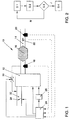
- FIG. 10 An arrangement 10 of an internal combustion engine 12 is shown in FIG a catalytic converter 16 arranged in an exhaust gas duct 14 and two lambda probes 18, 20 includes.
- a temperature sensor 22 is additionally arranged downstream of the catalytic converter 16, with which an exhaust gas temperature can be detected.
- the catalyst 16 serves one Conversion of pollutants contained in the exhaust gas of the internal combustion engine 12.
- a ratio of an oxygen fraction to a fuel fraction in one to be burned Air-fuel mixture provides a lambda value.
- the lambda probe 18 can be an oxygen concentration immediately behind the internal combustion engine 12 detect, the oxygen concentration clearly assigned to a lambda value can be.
- a conversion rate of the catalytic converter 16 can be determined using a monitor the signal provided by the lambda probe 20 in a known manner.
- the Lambda value is continuously recorded according to the exemplary embodiment, that is, the Lambda probes 18, 20 are so-called broadband lambda probes.
- a range of measurements for Broadband lambda probes range from approximately 0.7 to ⁇ . How it works such probes is known, so that in the context of the present description should not be discussed in more detail.
- the measurement signals detected by the sensors 18, 20, 22 are fed into an engine control unit 24 read, evaluated and to control an operating mode of the Internal combustion engine 12 used.
- the internal combustion engine 12 is a means assigned, for example, an injection system 26 or an exhaust gas recirculation include.
- the exhaust gas recirculation can reduce the volume flow intake air by means of a throttle valve 28 and by simultaneous supply low-oxygen exhaust gas take place via an exhaust gas reflux valve 30. In this way it is Oxygen content of a via an intake pipe 32 of the internal combustion engine 12 provided intake air mass can be specified.
- Exhaust gas turbochargers of supercharged engines have at least one lambda probe behind them Turbine in the exhaust gas.
- FIG. 2 shows a block diagram for function monitoring of the lambda probes 18, 20.
- a step S1 in addition to that by the lambda probes 18, 20 Provided measurement signal determines a target signal.
- a model for the internal combustion engine is used for this 12.
- the model includes parameters such as the intake air mass, a injected fuel mass or a speed of the internal combustion engine 12. It is also conceivable to use other sizes, for example in the engine control unit 24 are provided to be used to optimize the model.
- the operating mode of the internal combustion engine 12 must be used for function monitoring can not be controlled according to a signal pattern, but any Operating points can be used for monitoring. It has proven to be advantageous a diagnosis period immediately after a load change or a change in the Let the speed of the internal combustion engine 12 begin.
- a ratio of the measurement signal to the target signal provides a control value (step S2).
- the control value KW or the correlated control value KW k is then compared in a step S3 with a predefinable limit value GW.
- the limit value GW can also be determined using the model for the internal combustion engine 12. If the control value KW or the correlated control value KW k is below the limit value GW, a new measuring cycle of the function monitoring can follow, starting with step S1. However, if the control value KW or the correlated control value KW k exceeds the limit value GW, a maintenance signal is generated in a step S4. The maintenance signal then serves, for example in an on-board diagnosis, to inform a vehicle driver. Furthermore, the maintenance signal can be used to provide the maintenance personnel with appropriate instructions.
Abstract
Description
Die Erfindung betrifft ein Verfahren zur Funktionsüberwachung einer in einem Abgaskanal
einer Verbrennungskraftmaschine angeordneten Lambda-Sonde mit den im Oberbegriff des
Anspruchs 1 genannten Merkmalen.The invention relates to a method for monitoring the function of an exhaust gas duct
an internal combustion engine arranged lambda probe with the in the preamble of
Zur Regelung eines Betriebsmodus der Verbrennungskraftmaschine ist es bekannt, in dem Abgaskanal wenigstens eine Lambda-Sonde, insbesondere eine Breitband-Lambda-Sonde, anzuordnen. Mit Hilfe der Lambda-Sonde kann eine Sauerstoffkonzentration in einem Abgas erfaßt werden und ein Rückschluß auf das Verhältnis eines Sauerstoffanteils zu einem Kraftstoffanteil in dem dem Verbrennungsprozeß zugeführten Luft-Kraftstoff-Gemisch erfolgen. Breitband-Lambda-Sonden ermöglichen eine Messung von Lambda in einem Bereich von zirka 0,7 bis ∞.To control an operating mode of the internal combustion engine, it is known in which Exhaust channel at least one lambda probe, in particular a broadband lambda probe, to arrange. With the help of the lambda probe, an oxygen concentration in an exhaust gas can be detected and a conclusion on the ratio of an oxygen fraction to a fuel fraction take place in the air-fuel mixture supplied to the combustion process. Broadband lambda probes enable measurement of lambda in a range of about 0.7 to ∞.
In modernen Verbrennungskraftmaschinen wird das durch die Lambda-Sonde bereitgestellte Meßsignal zur Regelung des Luft-Kraftstoff-Gemisches entsprechend den gegebenen Anforderungen an die Verbrennungskraftmaschine genutzt (Lambda-Regelung). Dazu wird üblicherweise das Meßsignal in ein Motorsteuergerät eingelesen und dient dort als Basis für Maßnahmen, die beispielsweise eine Regelung eines Einspritzsystems oder einer Ansaugluft umfassen.In modern internal combustion engines, this is provided by the lambda probe Measurement signal for controlling the air-fuel mixture according to the given Requirements for the internal combustion engine used (lambda control). This will Usually the measurement signal is read into an engine control unit and serves as the basis for Measures that, for example, regulate an injection system or intake air include.
Üblicherweise dienen derartige Lambda-Sonden auch zur Überwachung von zusätzlich in dem Abgaskanal angeordneten Katalysatoren. An den Katalysatoren finden Redoxreaktionen statt, die zu einer Konvertierung von im Abgas enthaltenen Schadstoffen in weniger umweltrelevante Reaktionsprodukte führen. Lambda probes of this type are usually also used to monitor in addition the exhaust duct arranged catalysts. Redox reactions take place on the catalysts instead, which leads to a conversion of pollutants contained in the exhaust gas into less environmentally relevant Lead reaction products.
Wie bereits erläutert, wird der Betriebsmodus der Verbrennungskraftmaschine anhand des Meßsignals der Lambda-Sonde geregelt. Ist jedoch das bereitgestellte Meßsignal fehlerhaft aufgrund eines Defektes der Lambda-Sonde, so kann dies zum einen zur Einstellung eines verbrauchsungünstigen Betriebsmodus führen, und zum anderen kann gegebenenfalls eine Reduktion einer Schadstoffemission mittels der Katalysatoren nicht mehr in dem erforderlichen Maße gewährt werden.As already explained, the operating mode of the internal combustion engine is based on the Measurement signal of the lambda probe regulated. However, the measurement signal provided is faulty due to a defect in the lambda probe, this can on the one hand result in the setting of a lead to low-consumption operating mode, and on the other hand one can possibly Reduction of pollutant emissions by means of the catalysts no longer in the necessary dimensions are granted.
Der Erfindung liegt die Aufgabe zugrunde, ein Verfahren zur Verfügung zu stellen, das eine Funktionsüberwachung der Lambda-Sonde erlaubt und damit eine Behebung möglicher Defekte der Lambda-Sonde ermöglicht.The invention has for its object to provide a method that a Functional monitoring of the lambda probe allowed and thus possible rectification Defects in the lambda probe enabled.
Erfindungsgemäß wird diese Aufgabe durch das Verfahren zur Funktionsüberwachung der in
dem Abgaskanal der Verbrennungskraftmaschine angeordneten Lambda-Sonde mit den im
Anspruch 1 genannten Merkmalen gelöst. Dadurch, daß
Zur Kompensation statistischer Ausreißer ist vorgesehen, eine vorgebbare Anzahl der Kontrollwerte zunächst einer Korrelationsrechnung, insbesondere einer Kreuzkorrelation, zu unterwerfen. Die Korrelationsrechnung liefert dann einen korrelierten Kontrollwert. Beim Überschreiten des Kontrollwertes oder des korrelierten Kontrollwertes über den Grenzwert wird in bevorzugter Weise ein Wartungssignal erzeugt (On-board-Diagnose). Anhand des Wartungssignales kann dann eine entsprechende Information eines Fahrzeugführers erfolgen beziehungsweise dem Wartungspersonal eine notwendige Wartungsmaßnahme vorgeschlagen werden. To compensate for statistical outliers, a predeterminable number of Control values first of all to a correlation calculation, in particular a cross-correlation subject. The correlation calculation then delivers a correlated control value. At the Exceeding the control value or the correlated control value above the limit value a maintenance signal is generated in a preferred manner (on-board diagnosis). Based on the Maintenance signals can then provide appropriate information to a vehicle driver the maintenance personnel must carry out a necessary maintenance measure be proposed.
In vorteilhafter Ausgestaltung der Erfindung ist vorgesehen, den Diagnosezeitraum derart zu wählen, daß er sich unmittelbar einem Lastwechsel oder einer Änderung einer Drehzahl der Verbrennungskraftmaschine anschließt, da hier besonders signifikante Meßsignale vorliegen. Es ist demnach nicht notwendig, zur Funktionsüberwachung der Lambda-Sonde spezielle Signalmuster ablaufen zu lassen und damit den Regelbetrieb der Verbrennungskraftmaschine zu unterbrechen.In an advantageous embodiment of the invention, it is provided that the diagnosis period is such choose that he immediately a load change or a change in speed of the Internal combustion engine connects, since there are particularly significant measurement signals. It is therefore not necessary to use special functions for monitoring the lambda probe Let signal patterns run and thus the normal operation of the Interrupt internal combustion engine.
In das Modell für die Verbrennungskraftmaschine fließen Parameter ein, wie eine Ansaugluftmasse, eine Kraftstoffmasse und die Drehzahl. Selbstverständlich können auch andere Betriebsgrößen, die üblicherweise in einem Motorsteuergerät bereitgestellt werden, zur genaueren Anpassung des Modells verwendet werden.Parameters, such as one, flow into the model for the internal combustion engine Intake air mass, a fuel mass and the speed. Of course you can too other operating variables that are usually provided in an engine control unit, can be used to adjust the model more precisely.
Weitere bevorzugte Ausgestaltungen der Erfindung ergeben sich aus den übrigen, in den Unteransprüchen genannten Merkmalen.Further preferred refinements of the invention result from the others in the Characteristics mentioned subclaims.
Die Erfindung wird nachfolgend in einem Ausführungsbeispiel anhand der zugehörigen Zeichnungen näher erläutert. Es zeigen:
Figur 1- eine Anordnung von Lambda-Sonden in einem Abgaskanal einer Verbrennungskraftmaschine und
Figur 2- ein Blockschaltbild zur Funktionsüberwachung der Lambda-Sonden.
- Figure 1
- an arrangement of lambda probes in an exhaust duct of an internal combustion engine and
- Figure 2
- a block diagram for monitoring the function of the lambda probes.
In der Figur 1 ist eine Anordnung 10 einer Verbrennungskraftmaschine 12 dargestellt, die
einen in einem Abgaskanal 14 angeordneten Katalysator 16 und zwei Lambda-Sonden 18,
20 umfaßt. Stromab des Katalysators 16 ist zusätzlich ein Temperatursensor 22 angeordnet,
mit dem eine Abgastemperatur erfaßt werden kann. Der Katalysator 16 dient einer
Konvertierung von im Abgas der Verbrennungskraftmaschine 12 enthaltenen Schadstoffen.An
Ein Verhältnis eines Sauerstoffanteils zu einem Kraftstoffanteil in einem zu verbrennenden
Luft-Kraftstoff-Gemisch liefert einen Lambdawert. Insbesondere mit Hilfe der Lambda-Sonde
18 läßt sich eine Sauerstoffkonzentration unmittelbar hinter der Verbrennungskraftmaschine
12 erfassen, wobei die Sauerstoffkonzentration eindeutig einem Lambdawert zugeordnet
werden kann. Ferner läßt sich eine Konvertierungsrate des Katalysators 16 anhand eines
durch die Lambda-Sonde 20 bereitgestellten Signals in bekannter Weise überwachen. Der
Lambdawert wird gemäß dem Ausführungsbeispiel kontinuierlich erfaßt, das heißt, die
Lambda-Sonden 18, 20 sind sogenannte Breitband-Lambda-Sonden. Ein Meßwertbereich für
Breitband-Lambda-Sonden erstreckt sich von Lambda zirka 0,7 bis ∞. Die Funktionsweise
derartiger Sonden ist bekannt, so daß im Rahmen der vorliegenden Beschreibung hierauf
nicht näher eingegangen werden soll.A ratio of an oxygen fraction to a fuel fraction in one to be burned
Air-fuel mixture provides a lambda value. Especially with the help of the
Die mittels der Sensoren 18, 20, 22 erfaßten Meßsignale werden in ein Motorsteuergerät 24
eingelesen, ausgewertet und zur Regelung eines Betriebsmodus der
Verbrennungskraftmaschine 12 genutzt. Dazu sind der Verbrennungskraftmaschine 12 Mittel
zugeordnet, die beispielsweise ein Einspritzsystem 26 oder eine Abgasrückführung
umfassen. Durch die Abgasrückführung kann eine Reduzierung eines Volumenstromes
angesaugter Luft mittels einer Drosselklappe 28 und durch gleichzeitige Zuführung
sauerstoffarmen Abgases über ein Abgasrückflußventil 30 erfolgen. Auf diese Weise ist der
Sauerstoffanteil einer über ein Saugrohr 32 der Verbrennungskraftmaschine 12
bereitgestellten Ansaugluftmasse vorgebbar. Im Falle hier nicht dargestellter durch
Abgasturbolader aufgeladener Motoren sitzt zumindest eine Lambda-Sonde hinter der
Turbine im Abgas.The measurement signals detected by the
Die Figur 2 zeigt ein Blockschaltbild zur Funktionsüberwachung der Lambda-Sonden 18, 20.
Zunächst wird in einem Schritt S1 neben dem durch die Lambda-Sonden 18, 20 zur
Verfügung gestellten Meßsignal ein Sollsignal ermittelt. Dazu dient ein Modell für die Verbrennungskraftmaschine
12. Das Modell umfaßt Parameter, wie die Ansaugluftmasse, eine
eingespritzte Kraftstoffmasse oder auch eine Drehzahl der Verbrennungskraftmaschine 12.
Ebenso ist denkbar, auch andere Größen, die beispielsweise in dem Motorsteuergerät 24
bereitgestellt werden, zur Optimierung des Modells heranzuziehen.FIG. 2 shows a block diagram for function monitoring of the
Der Betriebsmodus der Verbrennungskraftmaschine 12 muß zur Funktionsüberwachung
nicht entsprechend einem Signalmuster gesteuert werden, sondern es können beliebige
Betriebspunkte für die Überwachung genutzt werden. Als vorteilhaft hat es sich erwiesen,
einen Diagnosezeitraum unmittelbar nach einem Lastwechsel oder einer Änderung der
Drehzahl der Verbrennungskraftmaschine 12 beginnen zu lassen. The operating mode of the
Ein Verhältnis des Meßsignals zum Sollsignal liefert einen Kontrollwert (Schritt S2). Zur Kompensation statistischer Ausreißer ist es dabei vorteilhaft, zunächst eine vorgebbare Anzahl der Kontrollwerte KW in eine Korrelationsrechnung einzubeziehen, die einen korrelierten Kontrollwert KWk liefert.A ratio of the measurement signal to the target signal provides a control value (step S2). In order to compensate for statistical outliers, it is advantageous to first include a predeterminable number of control values KW in a correlation calculation, which delivers a correlated control value KW k .
Der Kontrollwert KW oder der korrelierte Kontrollwert KWk wird anschließend in einem Schritt
S3 mit einem vorgebbaren Grenzwert GW verglichen. Auch der Grenzwert GW kann anhand
des Modells für die Verbrennungskraftmaschine 12 festgelegt werden. Liegt der Kontrollwert
KW beziehungsweise der korrelierte Kontrollwert KWk unterhalb des Grenzwertes GW, kann
sich ein erneuter Meßzyklus der Funktionsüberwachung beginnend mit dem Schritt S1 anschließen.
Überschreitet jedoch der Kontrollwert KW beziehungsweise der korrelierte
Kontrollwert KWk den Grenzwert GW, so wird in einem Schritt S4 ein Wartungssignal
erzeugt. Das Wartungssignal dient dann, beispielsweise in einer On-board-Diagnose, zur
Information eines Fahrzeugführers. Weiterhin kann das Wartungssignal dazu genutzt
werden, dem Wartungspersonal entsprechende Instruktionen zur Verfügung zu stellen.The control value KW or the correlated control value KW k is then compared in a step S3 with a predefinable limit value GW. The limit value GW can also be determined using the model for the
Claims (6)
Applications Claiming Priority (2)
| Application Number | Priority Date | Filing Date | Title |
|---|---|---|---|
| DE19936355A DE19936355A1 (en) | 1999-08-03 | 1999-08-03 | Procedure for the plausibility check of engine sizes and sensor sizes using a continuous lambda probe |
| DE19936355 | 1999-08-03 |
Publications (3)
| Publication Number | Publication Date |
|---|---|
| EP1074718A2 true EP1074718A2 (en) | 2001-02-07 |
| EP1074718A3 EP1074718A3 (en) | 2001-09-26 |
| EP1074718B1 EP1074718B1 (en) | 2004-11-10 |
Family
ID=7916920
Family Applications (1)
| Application Number | Title | Priority Date | Filing Date |
|---|---|---|---|
| EP00115537A Expired - Lifetime EP1074718B1 (en) | 1999-08-03 | 2000-07-19 | Method for testing plausibility of engine and probe parameters using a wide range lambda sensor |
Country Status (3)
| Country | Link |
|---|---|
| EP (1) | EP1074718B1 (en) |
| AT (1) | ATE282144T1 (en) |
| DE (2) | DE19936355A1 (en) |
Cited By (8)
| Publication number | Priority date | Publication date | Assignee | Title |
|---|---|---|---|---|
| DE102004033325B4 (en) * | 2003-07-10 | 2006-05-24 | Honda Motor Co., Ltd. | Diagnostic device for an exhaust gas sensor |
| EP1746276A2 (en) | 2005-07-22 | 2007-01-24 | Robert Bosch Gmbh | Monitoring of exhaust emission limits |
| WO2009011191A1 (en) * | 2007-07-19 | 2009-01-22 | Toyota Jidosha Kabushiki Kaisha | Abnormality detection device for internal combustion engine and air/fuel ratio control apparatus for internal combustion engine |
| WO2011018317A1 (en) | 2009-08-10 | 2011-02-17 | Robert Bosch Gmbh | Method and device for dynamically diagnosing an exhaust gas probe |
| WO2013087262A1 (en) * | 2011-12-12 | 2013-06-20 | Robert Bosch Gmbh | Method and device for the dynamic monitoring of gas sensors |
| WO2013110385A1 (en) * | 2012-01-25 | 2013-08-01 | Robert Bosch Gmbh | Method and control unit for determining a dead time of an exhaust gas sensor of an internal combustion engine |
| CN103967567A (en) * | 2013-02-04 | 2014-08-06 | 罗伯特·博世有限公司 | Method For Operating Oxygen Sensor Arrangement In Exhaust Gas System Of Internal Combustion Engine |
| WO2022084067A1 (en) * | 2020-10-23 | 2022-04-28 | Vitesco Technologies GmbH | Calculator for diagnosing fouling of a vehicle probe |
Families Citing this family (7)
| Publication number | Priority date | Publication date | Assignee | Title |
|---|---|---|---|---|
| DE10029633A1 (en) * | 2000-04-07 | 2001-10-11 | Volkswagen Ag | Multi-flow exhaust system of a multi-cylinder engine and method for controlling an air-fuel ratio |
| DE10111586A1 (en) | 2001-03-10 | 2002-09-12 | Volkswagen Ag | Process for operating internal combustion engines |
| DE10128969C1 (en) * | 2001-06-15 | 2002-12-12 | Audi Ag | Method for diagnosing guide probe fitted downstream from catalytic converter in system for controlling engine, involves detecting oxygen content in exhaust system for an internal combustion engine. |
| DE10250219A1 (en) * | 2002-10-23 | 2004-05-06 | Volkswagen Ag | Regulator and method for regulating a NOx sensor arranged in an exhaust gas duct of an internal combustion engine |
| DE10307342B4 (en) * | 2003-02-21 | 2005-08-11 | Volkswagen Ag | Device and method for model-based on-board diagnostics |
| DE102005016075B4 (en) * | 2005-04-08 | 2007-04-12 | Audi Ag | Method for diagnosing a lambda probe assigned to the exhaust gas catalytic converter of an internal combustion engine |
| JP4816773B2 (en) * | 2009-07-16 | 2011-11-16 | 株式会社デンソー | Exhaust component concentration sensor response detection device |
Citations (3)
| Publication number | Priority date | Publication date | Assignee | Title |
|---|---|---|---|---|
| US5550762A (en) * | 1993-12-20 | 1996-08-27 | Doll; John A. | Diagnostic system for electronic automotive system |
| US5676119A (en) * | 1995-09-25 | 1997-10-14 | Honda Giken Kogyo Kabushiki Kaisha | Air-fuel ratio control system for internal combustion engines |
| US5781878A (en) * | 1995-06-05 | 1998-07-14 | Nippondenso Co., Ltd. | Apparatus and method for diagnosing degradation or malfunction of oxygen sensor |
Family Cites Families (3)
| Publication number | Priority date | Publication date | Assignee | Title |
|---|---|---|---|---|
| DE19612212B4 (en) * | 1995-03-31 | 2005-12-08 | Denso Corp., Kariya | Diagnostic device for an air / fuel ratio sensor |
| DE19606652B4 (en) * | 1996-02-23 | 2004-02-12 | Robert Bosch Gmbh | Method of setting the air-fuel ratio for an internal combustion engine with a downstream catalytic converter |
| DE19844994C2 (en) * | 1998-09-30 | 2002-01-17 | Siemens Ag | Method for diagnosing a continuous lambda probe |
-
1999
- 1999-08-03 DE DE19936355A patent/DE19936355A1/en not_active Withdrawn
-
2000
- 2000-07-19 EP EP00115537A patent/EP1074718B1/en not_active Expired - Lifetime
- 2000-07-19 DE DE50008573T patent/DE50008573D1/en not_active Expired - Fee Related
- 2000-07-19 AT AT00115537T patent/ATE282144T1/en not_active IP Right Cessation
Patent Citations (3)
| Publication number | Priority date | Publication date | Assignee | Title |
|---|---|---|---|---|
| US5550762A (en) * | 1993-12-20 | 1996-08-27 | Doll; John A. | Diagnostic system for electronic automotive system |
| US5781878A (en) * | 1995-06-05 | 1998-07-14 | Nippondenso Co., Ltd. | Apparatus and method for diagnosing degradation or malfunction of oxygen sensor |
| US5676119A (en) * | 1995-09-25 | 1997-10-14 | Honda Giken Kogyo Kabushiki Kaisha | Air-fuel ratio control system for internal combustion engines |
Cited By (20)
| Publication number | Priority date | Publication date | Assignee | Title |
|---|---|---|---|---|
| DE102004033325B4 (en) * | 2003-07-10 | 2006-05-24 | Honda Motor Co., Ltd. | Diagnostic device for an exhaust gas sensor |
| EP1746276A2 (en) | 2005-07-22 | 2007-01-24 | Robert Bosch Gmbh | Monitoring of exhaust emission limits |
| EP1746276A3 (en) * | 2005-07-22 | 2013-05-22 | Robert Bosch Gmbh | Monitoring of exhaust emission limits |
| WO2009011191A1 (en) * | 2007-07-19 | 2009-01-22 | Toyota Jidosha Kabushiki Kaisha | Abnormality detection device for internal combustion engine and air/fuel ratio control apparatus for internal combustion engine |
| CN101755115A (en) * | 2007-07-19 | 2010-06-23 | 丰田自动车株式会社 | Abnormality detection device for internal combustion engine and air/fuel ratio control apparatus for internal combustion engine |
| US8050852B2 (en) | 2007-07-19 | 2011-11-01 | Toyota Jidosha Kabushiki Kaisha | Abnormality detection device for internal combustion engine and air/fuel ratio control apparatus for internal combustion engine |
| CN101755115B (en) * | 2007-07-19 | 2013-04-10 | 丰田自动车株式会社 | Abnormality detection device for internal combustion engine and air/fuel ratio control apparatus for internal combustion engine |
| US8646324B2 (en) | 2009-08-10 | 2014-02-11 | Robert Bosch Gmbh | Method and device for dynamically diagnosing an exhaust gas probe |
| WO2011018317A1 (en) | 2009-08-10 | 2011-02-17 | Robert Bosch Gmbh | Method and device for dynamically diagnosing an exhaust gas probe |
| CN102472186A (en) * | 2009-08-10 | 2012-05-23 | 罗伯特·博世有限公司 | Method and device for dynamically diagnosing an exhaust gas probe |
| US20120222474A1 (en) * | 2009-08-10 | 2012-09-06 | Robert Bosch Gmbh | Method and device for dynamically diagnosing an exhaust gas probe |
| CN102472186B (en) * | 2009-08-10 | 2015-06-17 | 罗伯特·博世有限公司 | Method and device for dynamically diagnosing an exhaust gas probe |
| WO2013087262A1 (en) * | 2011-12-12 | 2013-06-20 | Robert Bosch Gmbh | Method and device for the dynamic monitoring of gas sensors |
| US10060894B2 (en) | 2011-12-12 | 2018-08-28 | Robert Bosch Gmbh | Method and device for dynamic monitoring of gas sensors |
| WO2013110385A1 (en) * | 2012-01-25 | 2013-08-01 | Robert Bosch Gmbh | Method and control unit for determining a dead time of an exhaust gas sensor of an internal combustion engine |
| US9518893B2 (en) | 2012-01-25 | 2016-12-13 | Robert Bosch Gmbh | Method and control unit for determining a dead time of an exhaust gas sensor of an internal combustion engine |
| CN103967567A (en) * | 2013-02-04 | 2014-08-06 | 罗伯特·博世有限公司 | Method For Operating Oxygen Sensor Arrangement In Exhaust Gas System Of Internal Combustion Engine |
| CN103967567B (en) * | 2013-02-04 | 2018-03-30 | 罗伯特·博世有限公司 | A kind of method for running air inflow detector assembly in engine exhaust gas system |
| WO2022084067A1 (en) * | 2020-10-23 | 2022-04-28 | Vitesco Technologies GmbH | Calculator for diagnosing fouling of a vehicle probe |
| FR3115597A1 (en) * | 2020-10-23 | 2022-04-29 | Vitesco Technologies | Calculator for vehicle probe fouling diagnostics |
Also Published As
| Publication number | Publication date |
|---|---|
| EP1074718B1 (en) | 2004-11-10 |
| EP1074718A3 (en) | 2001-09-26 |
| ATE282144T1 (en) | 2004-11-15 |
| DE19936355A1 (en) | 2001-02-08 |
| DE50008573D1 (en) | 2004-12-16 |
Similar Documents
| Publication | Publication Date | Title |
|---|---|---|
| DE102008042549B4 (en) | Method and device for diagnosing an exhaust gas probe | |
| EP0492165B1 (en) | Procedure and device for testing catalytic converters | |
| EP1074718B1 (en) | Method for testing plausibility of engine and probe parameters using a wide range lambda sensor | |
| DE10319983B3 (en) | Device for regulating the lambda value in an I.C. engine with a catalyst arranged in the exhaust gas pipe, comprises a nitrogen oxides sensor arranged after a partial volume of the catalyst or downstream of the catalyst | |
| DE10111586A1 (en) | Process for operating internal combustion engines | |
| EP3527810A1 (en) | Method for operating a combustion engine | |
| DE102004038731A1 (en) | Method and device for operating an internal combustion engine | |
| EP2401485B1 (en) | Method for operating an exhaust gas system | |
| EP0530655B1 (en) | Method and apparatus for controlling an internal combustion engine and testing its catalytic converter | |
| DE10309422B4 (en) | Method and device for calibrating a NOx sensor | |
| DE102008042925B3 (en) | Cetane number determination involves injecting fuel for combustion in cylinder of internal combustion engine by using engine management system | |
| DE102008008985B4 (en) | Method for OSC-based diagnosis of a catalyst | |
| DE102006026739A1 (en) | Internal combustion engine e.g. diesel internal combustion engine, operating method, involves detecting intact or defective nitrogen oxide sensor or ammonia sensor or intact or defective controller | |
| DE10234340B4 (en) | Method for determining the loading state of a particle filter of an internal combustion engine | |
| EP1136670B1 (en) | Monitoring device and method of a 3-way catalyst in the exhaust pipe of an internal combustion engine | |
| DE102006011894B4 (en) | Method for correcting a signal provided by a lambda sensor | |
| WO2001006223A1 (en) | Method for detecting the state of a catalytic converter system | |
| DE102006002257B4 (en) | Method and device for operating an exhaust gas catalytic converter of an internal combustion engine | |
| DE10014881A1 (en) | Calibration of lambda sensors in exhaust system including NOx sensor downstream of three-way catalyst, first adjusts mixture to approach predetermined NOx signal | |
| DE102005046956B3 (en) | Method for detecting misfiring in combustion chamber of engine cylinder involves using operating parameter of engine and determining fault cause in injection system dependent on cylinder-specific uneven running value | |
| DE102018104258B4 (en) | Fuel determination technology | |
| EP1434049B1 (en) | Method of and device for monitoring the NOx signal of an NOx sensor | |
| DE10300939A1 (en) | Method and device for monitoring the NOx signal of a NOx sensor | |
| DE10261618B4 (en) | Runningirregularity evaluation process | |
| DE102005020139A1 (en) | Combustion misfire detection for internal combustion engine, involves detecting misfire based on given condition that depends on error signal, where signal depends on measuring signal of probe arranged upstream of converter |
Legal Events
| Date | Code | Title | Description |
|---|---|---|---|
| PUAI | Public reference made under article 153(3) epc to a published international application that has entered the european phase |
Free format text: ORIGINAL CODE: 0009012 |
|
| AK | Designated contracting states |
Kind code of ref document: A2 Designated state(s): AT BE CH CY DE DK ES FI FR GB GR IE IT LI LU MC NL PT SE |
|
| AX | Request for extension of the european patent |
Free format text: AL;LT;LV;MK;RO;SI |
|
| PUAL | Search report despatched |
Free format text: ORIGINAL CODE: 0009013 |
|
| AK | Designated contracting states |
Kind code of ref document: A3 Designated state(s): AT BE CH CY DE DK ES FI FR GB GR IE IT LI LU MC NL PT SE |
|
| AX | Request for extension of the european patent |
Free format text: AL;LT;LV;MK;RO;SI |
|
| RIC1 | Information provided on ipc code assigned before grant |
Free format text: 7F 02D 41/14 A, 7F 02D 41/22 B, 7F 01N 11/00 B |
|
| 17P | Request for examination filed |
Effective date: 20020326 |
|
| AKX | Designation fees paid |
Free format text: AT BE CH CY DE DK ES FI FR GB GR IE IT LI LU MC NL PT SE |
|
| 17Q | First examination report despatched |
Effective date: 20030115 |
|
| GRAP | Despatch of communication of intention to grant a patent |
Free format text: ORIGINAL CODE: EPIDOSNIGR1 |
|
| GRAS | Grant fee paid |
Free format text: ORIGINAL CODE: EPIDOSNIGR3 |
|
| GRAA | (expected) grant |
Free format text: ORIGINAL CODE: 0009210 |
|
| AK | Designated contracting states |
Kind code of ref document: B1 Designated state(s): AT BE CH CY DE DK ES FI FR GB GR IE IT LI LU MC NL PT SE |
|
| PG25 | Lapsed in a contracting state [announced via postgrant information from national office to epo] |
Ref country code: FI Free format text: LAPSE BECAUSE OF FAILURE TO SUBMIT A TRANSLATION OF THE DESCRIPTION OR TO PAY THE FEE WITHIN THE PRESCRIBED TIME-LIMIT Effective date: 20041110 Ref country code: NL Free format text: LAPSE BECAUSE OF FAILURE TO SUBMIT A TRANSLATION OF THE DESCRIPTION OR TO PAY THE FEE WITHIN THE PRESCRIBED TIME-LIMIT Effective date: 20041110 Ref country code: IT Free format text: LAPSE BECAUSE OF FAILURE TO SUBMIT A TRANSLATION OF THE DESCRIPTION OR TO PAY THE FEE WITHIN THE PRESCRIBED TIME-LIMIT;WARNING: LAPSES OF ITALIAN PATENTS WITH EFFECTIVE DATE BEFORE 2007 MAY HAVE OCCURRED AT ANY TIME BEFORE 2007. THE CORRECT EFFECTIVE DATE MAY BE DIFFERENT FROM THE ONE RECORDED. Effective date: 20041110 Ref country code: IE Free format text: LAPSE BECAUSE OF FAILURE TO SUBMIT A TRANSLATION OF THE DESCRIPTION OR TO PAY THE FEE WITHIN THE PRESCRIBED TIME-LIMIT Effective date: 20041110 Ref country code: FR Free format text: LAPSE BECAUSE OF NON-PAYMENT OF DUE FEES Effective date: 20041110 |
|
| REG | Reference to a national code |
Ref country code: GB Ref legal event code: FG4D Free format text: NOT ENGLISH |
|
| REG | Reference to a national code |
Ref country code: CH Ref legal event code: EP |
|
| REG | Reference to a national code |
Ref country code: IE Ref legal event code: FG4D Free format text: GERMAN |
|
| REF | Corresponds to: |
Ref document number: 50008573 Country of ref document: DE Date of ref document: 20041216 Kind code of ref document: P |
|
| PG25 | Lapsed in a contracting state [announced via postgrant information from national office to epo] |
Ref country code: GR Free format text: LAPSE BECAUSE OF FAILURE TO SUBMIT A TRANSLATION OF THE DESCRIPTION OR TO PAY THE FEE WITHIN THE PRESCRIBED TIME-LIMIT Effective date: 20050210 Ref country code: SE Free format text: LAPSE BECAUSE OF FAILURE TO SUBMIT A TRANSLATION OF THE DESCRIPTION OR TO PAY THE FEE WITHIN THE PRESCRIBED TIME-LIMIT Effective date: 20050210 Ref country code: DK Free format text: LAPSE BECAUSE OF FAILURE TO SUBMIT A TRANSLATION OF THE DESCRIPTION OR TO PAY THE FEE WITHIN THE PRESCRIBED TIME-LIMIT Effective date: 20050210 |
|
| PG25 | Lapsed in a contracting state [announced via postgrant information from national office to epo] |
Ref country code: ES Free format text: LAPSE BECAUSE OF FAILURE TO SUBMIT A TRANSLATION OF THE DESCRIPTION OR TO PAY THE FEE WITHIN THE PRESCRIBED TIME-LIMIT Effective date: 20050221 |
|
| GBT | Gb: translation of ep patent filed (gb section 77(6)(a)/1977) |
Effective date: 20050316 |
|
| NLV1 | Nl: lapsed or annulled due to failure to fulfill the requirements of art. 29p and 29m of the patents act | ||
| REG | Reference to a national code |
Ref country code: IE Ref legal event code: FD4D |
|
| PG25 | Lapsed in a contracting state [announced via postgrant information from national office to epo] |
Ref country code: AT Free format text: LAPSE BECAUSE OF NON-PAYMENT OF DUE FEES Effective date: 20050719 Ref country code: LU Free format text: LAPSE BECAUSE OF NON-PAYMENT OF DUE FEES Effective date: 20050719 Ref country code: CY Free format text: LAPSE BECAUSE OF FAILURE TO SUBMIT A TRANSLATION OF THE DESCRIPTION OR TO PAY THE FEE WITHIN THE PRESCRIBED TIME-LIMIT Effective date: 20050719 |
|
| PG25 | Lapsed in a contracting state [announced via postgrant information from national office to epo] |
Ref country code: CH Free format text: LAPSE BECAUSE OF NON-PAYMENT OF DUE FEES Effective date: 20050731 Ref country code: MC Free format text: LAPSE BECAUSE OF NON-PAYMENT OF DUE FEES Effective date: 20050731 Ref country code: LI Free format text: LAPSE BECAUSE OF NON-PAYMENT OF DUE FEES Effective date: 20050731 Ref country code: BE Free format text: LAPSE BECAUSE OF NON-PAYMENT OF DUE FEES Effective date: 20050731 |
|
| PLBE | No opposition filed within time limit |
Free format text: ORIGINAL CODE: 0009261 |
|
| STAA | Information on the status of an ep patent application or granted ep patent |
Free format text: STATUS: NO OPPOSITION FILED WITHIN TIME LIMIT |
|
| 26N | No opposition filed |
Effective date: 20050811 |
|
| EN | Fr: translation not filed | ||
| EN | Fr: translation not filed | ||
| REG | Reference to a national code |
Ref country code: CH Ref legal event code: PL |
|
| BERE | Be: lapsed |
Owner name: *VOLKSWAGEN A.G. Effective date: 20050731 |
|
| PG25 | Lapsed in a contracting state [announced via postgrant information from national office to epo] |
Ref country code: PT Free format text: LAPSE BECAUSE OF NON-PAYMENT OF DUE FEES Effective date: 20050410 |
|
| PGFP | Annual fee paid to national office [announced via postgrant information from national office to epo] |
Ref country code: GB Payment date: 20090612 Year of fee payment: 10 Ref country code: DE Payment date: 20090731 Year of fee payment: 10 |
|
| GBPC | Gb: european patent ceased through non-payment of renewal fee |
Effective date: 20100719 |
|
| PG25 | Lapsed in a contracting state [announced via postgrant information from national office to epo] |
Ref country code: DE Free format text: LAPSE BECAUSE OF NON-PAYMENT OF DUE FEES Effective date: 20110201 |
|
| REG | Reference to a national code |
Ref country code: DE Ref legal event code: R119 Ref document number: 50008573 Country of ref document: DE Effective date: 20110201 |
|
| PG25 | Lapsed in a contracting state [announced via postgrant information from national office to epo] |
Ref country code: GB Free format text: LAPSE BECAUSE OF NON-PAYMENT OF DUE FEES Effective date: 20100719 |