EP1074220A1 - Imaging system phantom - Google Patents
Imaging system phantom Download PDFInfo
- Publication number
- EP1074220A1 EP1074220A1 EP00306600A EP00306600A EP1074220A1 EP 1074220 A1 EP1074220 A1 EP 1074220A1 EP 00306600 A EP00306600 A EP 00306600A EP 00306600 A EP00306600 A EP 00306600A EP 1074220 A1 EP1074220 A1 EP 1074220A1
- Authority
- EP
- European Patent Office
- Prior art keywords
- phantom
- segment
- imaging system
- identifier
- plate
- Prior art date
- Legal status (The legal status is an assumption and is not a legal conclusion. Google has not performed a legal analysis and makes no representation as to the accuracy of the status listed.)
- Granted
Links
Images


Classifications
-
- A—HUMAN NECESSITIES
- A61—MEDICAL OR VETERINARY SCIENCE; HYGIENE
- A61B—DIAGNOSIS; SURGERY; IDENTIFICATION
- A61B6/00—Apparatus for radiation diagnosis, e.g. combined with radiation therapy equipment
- A61B6/58—Testing, adjusting or calibrating apparatus or devices for radiation diagnosis
- A61B6/582—Calibration
- A61B6/583—Calibration using calibration phantoms
-
- G—PHYSICS
- G01—MEASURING; TESTING
- G01R—MEASURING ELECTRIC VARIABLES; MEASURING MAGNETIC VARIABLES
- G01R33/00—Arrangements or instruments for measuring magnetic variables
- G01R33/20—Arrangements or instruments for measuring magnetic variables involving magnetic resonance
- G01R33/44—Arrangements or instruments for measuring magnetic variables involving magnetic resonance using nuclear magnetic resonance [NMR]
- G01R33/48—NMR imaging systems
- G01R33/58—Calibration of imaging systems, e.g. using test probes, Phantoms; Calibration objects or fiducial markers such as active or passive RF coils surrounding an MR active material
-
- G—PHYSICS
- G09—EDUCATION; CRYPTOGRAPHY; DISPLAY; ADVERTISING; SEALS
- G09B—EDUCATIONAL OR DEMONSTRATION APPLIANCES; APPLIANCES FOR TEACHING, OR COMMUNICATING WITH, THE BLIND, DEAF OR MUTE; MODELS; PLANETARIA; GLOBES; MAPS; DIAGRAMS
- G09B23/00—Models for scientific, medical, or mathematical purposes, e.g. full-sized devices for demonstration purposes
- G09B23/28—Models for scientific, medical, or mathematical purposes, e.g. full-sized devices for demonstration purposes for medicine
Definitions
- This invention relates generally to an imaging system and, more particularly, to a phantom for use with an imaging system.
- Medical imaging systems include a source that emits signals (including but not limited to x-ray, radio frequency, or sonar signals), and the signals are directed toward an object to be imaged.
- the emitted signals and the interposed object interact to produce a response that is received by one or more detectors.
- the imaging system then processes the detected response signals to generate an image of the object.
- a phantom for use with an imaging system, said phantom comprising: a plurality of segments, each said segment coupled to at least one other said segment to enclose a volume, each said segment having a unique segment identifier; and an inner plate positioned within said volume, said inner plate coupled to at least one said segment.
- the inner plate may comprise a unique plate identifier.
- the phantom may further comprise at least one inner block positioned within said volume, each said inner block disposed upon said inner plate.
- Each inner block may comprises a unique block identifier.
- the plurality of segments may substantially form a polyhedron which may comprise twenty segments. Each segment may be substantially a triangle.
- Each segment identifier may outline an opening through each corresponding segment.
- Each said segment identifier may comprise at least one alphanumeric character and may further comprise a period.
- the segments and the inner plate may comprise a plastic material.
- the plate identifier may outline an opening through the inner plate and each block identifier may outline an opening through each said corresponding inner block.
- the plate identifier may comprises at least one alphanumeric character and may further comprises a period.
- Each block identifier may comprise at least one alphanumeric character and may further comprises a period.
- the phantom may comprises at least one inner block substantially orthogonal to the inner plate. It may comprise at least two said inner blocks substantially orthogonal to one another.
- an imaging object for use with an imaging system, said imaging object comprising: a phantom comprising a plurality of segments, each said segment coupled to at least one other said segment to enclose a volume, each said segment having a unique segment identifier, said phantom further comprising an inner plate positioned within said volume, said inner plate coupled to at least one said segment; and a stand coupled to and supporting said phantom.
- the stand may comprise a base and a support member.
- the stand may comprises a plastics material.
- the imaging system may include a table for supporting objects to be imaged and the stand may be configured to orient the inner plate horizontally as the phantom rests on the table.
- a container may be configured to receive the phantom and the stand and may comprise a means for sealing liquid inside the container.
- a method for verifying correctness of image orientation and image annotation in an imaging system comprising the steps of: orienting a phantom at a particular location relative to the imaging system, the phantom including a plurality of segments and an inner plate, each segment having a unique segment identifier, the plate having a unique plate identifier; generating an image of the phantom; and comparing the generated image to the configuration and orientation of the phantom.
- the phantom may include at least one inner block, at least one of the inner blocks being orthogonal to the inner plate, and the step of orienting a phantom at a particular location relative to the imaging system may comprises the step of aligning the inner blocks and the inner plate orthogonally to the imaging system.
- Each inner block may have a unique block identifier
- the step of generating an image of the phantom may comprises the step of orienting the source relative to the phantom's segment identifiers, plate identifier and block identifiers.
- Each segment identifier may outline an opening through the corresponding segment
- the plate identifier may outline an opening through the inner plate
- each block identifier may outline an opening through the corresponding inner block
- the step of orienting the source relative to the phantom's segment identifiers, plate identifier and block identifiers may comprise orienting the source for image projection through one or more of the openings outlined by the segment identifiers, plate identifier and block identifiers in the corresponding segments, plate or blocks.
- the step of generating an image of the phantom may comprise the steps of: orienting the source for image projection relative to a particular segment, the inner plate or a particular inner block; and generating an image of such segment, inner plate or inner block.
- the method may further comprise the step of: placing the phantom within a container; and filling the container with a liquid.
- the imaging system may be a real-time interactive imaging system.
- present invention in one aspect, is a phantom that facilitates training operators with respect to positioning the image system components, and includes an inner plate enclosed and supported by a plurality of segments which join together to form an icosahedron. Each segment includes a unique identifier, for example, an alphanumeric character.
- Two inner blocks are seated on the inner plate which, together with the inner blocks, indicate orthogonal planes (i.e. axial, sagittal, and coronal).
- the inner plate and inner blocks have unique identifiers that, together with the segment identifiers, are used to orient the imaging system source during imaging.
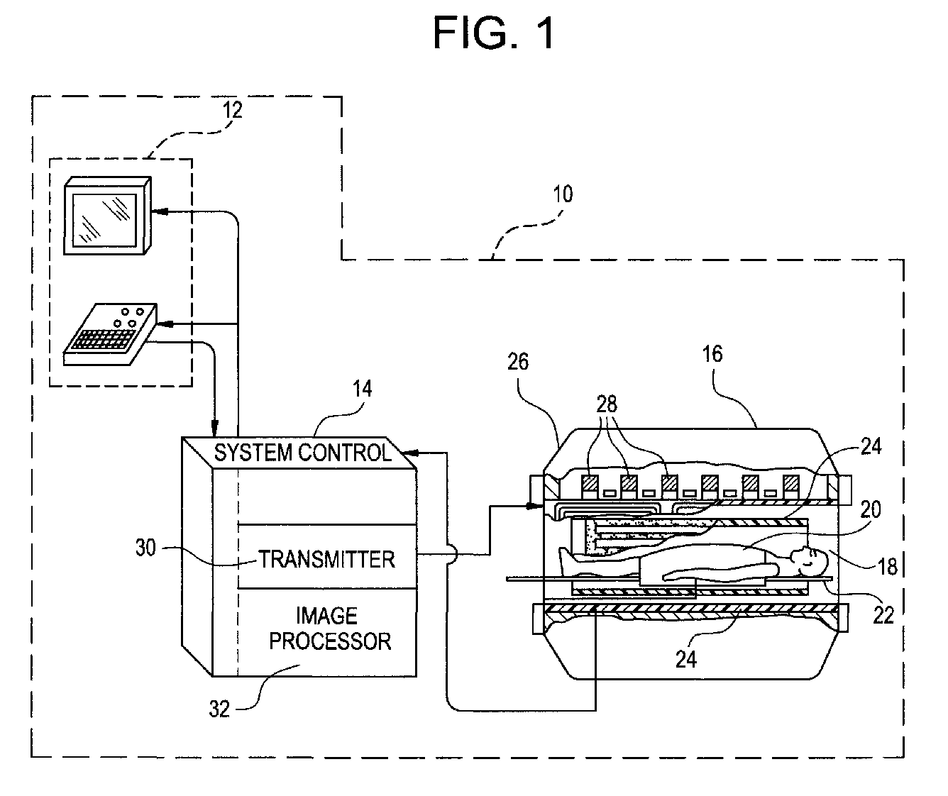
- Figure 1 is a pictorial view of an MRI imaging system.
- Figure 2 is an elevational view of an embodiment of a phantom.
- Figure 3 is an exploded perspective view of the phantom shown in Figure 2.
- an MRI imaging system 10 includes an operator console 12 from which the operator controls imaging system 10.
- a system control 14 receives commands from the operator indicating the scan sequence to be performed and transmits imaging control signals to an MRI scanner 16.
- patient or object 20 is positioned on a table 22 and is surrounded by a magnetic coil or detector 24.
- Magnetic coil 24 is part of a magnet assembly 26, which also includes a polarizing magnet 28.
- Polarizing magnet 28 subjects object 20 to a uniform magnetic field.
- a transmitter or source 30 included in system control 14 transmits radio frequency pulses to magnet assembly 26.
- the resulting signals emitted by the excited spins in object 20 are picked up by magnetic coil 24, transmitted to system control 14 and reconstructed into an image by an image processor 32.
- the operator of imaging system 10 is able to view the image on console 12. If imaging system 10 is interactive in real time, the operator is able to view images and alter the scan sequence as it progresses.
- a phantom 34 for use with imaging system 10 includes twenty triangular segments or sides 36. Segments 36 are coupled together to form a substantially polyhedral shape enclosing a volume 38. Each segment 36 includes a unique segment identifier 40. Phantom 34 is coupled to and supported by a stand 42, which includes a base 44 and a support member 46.
- Figure 3 is an exploded view of phantom 34.
- phantom 34 includes an inner plate 48 surrounded by and connected to several segments 36.
- Inner plate 48 includes a unique plate identifier 50.
- Two inner blocks 52 are positioned over inner plate 48.
- Each inner block 52 includes a unique block identifier 54.
- Each segment identifier 40, block identifier 54 and plate identifier 50 includes an alphanumeric character 56 and also includes a period 58.
- Each segment identifier 40 outlines an opening 62 through the corresponding segment 36.
- each block identifier 54 outlines an opening 66 through the corresponding inner block 52
- plate identifier 50 outlines an opening 70 through inner plate 48.
- a container (not shown) is configured to receive phantom 34 and stand 42. The container then is filled with a liquid, sealed and placed on table 22 for imaging.
- Segments 36, inner plate 48, inner blocks 52, and stand 42 in an exemplary embodiment, are fabricated from acrylic sheet and joined together with Weld-On 40 adhesive available from IPS Corporation, Compton, CA 90220.
- openings 62, 66 and 70 are visible from multiple directions and are used to identify the direction from which phantom 34 is being viewed.
- Inner blocks 52 and inner plate 48 are orthogonal to one another, thereby providing orthogonal axes for imaging system alignment purposes.
- block identifiers 54 and plate identifier 50 are denoted as "A.”, "S.” and “C.” respectively, to indicate axial, sagittal and coronal planes.
- Stand 42 is configured to orient inner plate 48 horizontally when phantom 34 is positioned on table 22.
- An imaging system user prepares for imaging by orienting phantom 34 on table 22 at a particular location relative to imaging system 10. Specifically, inner blocks 52 and inner plate 48 are aligned orthogonally to imaging system 10.
- an imaging system user orients source 30 relative to a particular segment 36, inner plate 48, and/or a particular inner block 52. The user then generates an image of segment 36, inner plate 48, and/or inner block 52 for comparison with the known configuration and orientation of phantom 34.
- the imaging system operator uses segment identifiers 40, plate identifier 50, and (if present in the particular embodiment) block identifiers 54 as guides in maneuvering in three dimensions. Based on the image generated, the operator can ascertain whether the desired positioning was achieved.
- the above described phantom facilitates and shortens time needed for training imaging system operators, particularly for interactive real-time imaging systems.
- the phantom provides a variety of surfaces, angles and edges in scanning locations known to the imaging system operator.
- the phantom enables an operator to practice scanning from many directions, or alternatively to generate images to verify an imaging system's image correctness and annotation.
- phantom include segments 36, inner plate 48 and inner blocks 52 of shape and number other than those described above and that join together to form a polyhedron other than an icosahedron. Segment, plate and block identifiers other than alphanumeric characters followed by periods also can be used. Further, the phantom and stand can be fabricated from materials other than acrylic, such as other plastics. In addition, although the invention has been described occasionally with reference to a MRI system, the invention is not limited to use with MRI systems, and may be used with other types of imaging systems.
Abstract
Description
- This invention relates generally to an imaging system and, more particularly, to a phantom for use with an imaging system.
- Medical imaging systems include a source that emits signals (including but not limited to x-ray, radio frequency, or sonar signals), and the signals are directed toward an object to be imaged. The emitted signals and the interposed object interact to produce a response that is received by one or more detectors. The imaging system then processes the detected response signals to generate an image of the object.
- With real-time interactive imaging systems, a user controls movement of system components in three-dimensional space while performing scans. Inexperienced operators often have difficulty in visualizing the object in three-dimensional space and maneuvering the system in three dimensions while scanning. In addition, proper verification of image orientation and image annotation is difficult, particularly for double angle oblique scans acquired in real time.
- According to a first aspect of the invention, there is provided a phantom for use with an imaging system, said phantom comprising: a plurality of segments, each said segment coupled to at least one other said segment to enclose a volume, each said segment having a unique segment identifier; and an inner plate positioned within said volume, said inner plate coupled to at least one said segment.
- The inner plate may comprise a unique plate identifier.
- The phantom may further comprise at least one inner block positioned within said volume, each said inner block disposed upon said inner plate. Each inner block may comprises a unique block identifier.
- The plurality of segments may substantially form a polyhedron which may comprise twenty segments. Each segment may be substantially a triangle.
- Each segment identifier may outline an opening through each corresponding segment. Each said segment identifier may comprise at least one alphanumeric character and may further comprise a period.
- The segments and the inner plate may comprise a plastic material.
- The plate identifier may outline an opening through the inner plate and each block identifier may outline an opening through each said corresponding inner block.
- The plate identifier may comprises at least one alphanumeric character and may further comprises a period.
- Each block identifier may comprise at least one alphanumeric character and may further comprises a period.
- The phantom may comprises at least one inner block substantially orthogonal to the inner plate. It may comprise at least two said inner blocks substantially orthogonal to one another.
- According to a second aspect of the invention, there is provided an imaging object for use with an imaging system, said imaging object comprising: a phantom comprising a plurality of segments, each said segment coupled to at least one other said segment to enclose a volume, each said segment having a unique segment identifier, said phantom further comprising an inner plate positioned within said volume, said inner plate coupled to at least one said segment; and a stand coupled to and supporting said phantom.
- The stand may comprise a base and a support member.
- The stand may comprises a plastics material.
- The imaging system may include a table for supporting objects to be imaged and the stand may be configured to orient the inner plate horizontally as the phantom rests on the table.
- A container may be configured to receive the phantom and the stand and may comprise a means for sealing liquid inside the container.
- According to a third aspect of the invention, there is provided a method for verifying correctness of image orientation and image annotation in an imaging system, the imaging system including a source and a detector, said method comprising the steps of: orienting a phantom at a particular location relative to the imaging system, the phantom including a plurality of segments and an inner plate, each segment having a unique segment identifier, the plate having a unique plate identifier; generating an image of the phantom; and comparing the generated image to the configuration and orientation of the phantom.
- The phantom may include at least one inner block, at least one of the inner blocks being orthogonal to the inner plate, and the step of orienting a phantom at a particular location relative to the imaging system may comprises the step of aligning the inner blocks and the inner plate orthogonally to the imaging system.
- Each inner block may have a unique block identifier, and the step of generating an image of the phantom may comprises the step of orienting the source relative to the phantom's segment identifiers, plate identifier and block identifiers.
- Each segment identifier may outline an opening through the corresponding segment, the plate identifier may outline an opening through the inner plate, each block identifier may outline an opening through the corresponding inner block; and the step of orienting the source relative to the phantom's segment identifiers, plate identifier and block identifiers may comprise orienting the source for image projection through one or more of the openings outlined by the segment identifiers, plate identifier and block identifiers in the corresponding segments, plate or blocks.
- The step of generating an image of the phantom may comprise the steps of: orienting the source for image projection relative to a particular segment, the inner plate or a particular inner block; and generating an image of such segment, inner plate or inner block.
- The method may further comprise the step of: placing the phantom within a container; and filling the container with a liquid.
- The imaging system may be a real-time interactive imaging system.
- Thus, present invention, in one aspect, is a phantom that facilitates training operators with respect to positioning the image system components, and includes an inner plate enclosed and supported by a plurality of segments which join together to form an icosahedron. Each segment includes a unique identifier, for example, an alphanumeric character. Two inner blocks are seated on the inner plate which, together with the inner blocks, indicate orthogonal planes (i.e. axial, sagittal, and coronal). The inner plate and inner blocks have unique identifiers that, together with the segment identifiers, are used to orient the imaging system source during imaging.
- The invention will now be described in greater detail, by way of example, with reference to the drawings, in which:-
- Figure 1 is a pictorial view of an MRI imaging system.
- Figure 2 is an elevational view of an embodiment of a phantom.
- Figure 3 is an exploded perspective view of the phantom shown in Figure 2.
- Referring to Figure 1, major components of an
MRI imaging system 10 include anoperator console 12 from which the operator controlsimaging system 10. Asystem control 14 receives commands from the operator indicating the scan sequence to be performed and transmits imaging control signals to anMRI scanner 16. Within acylindrical bore 18 ofscanner 16, patient orobject 20 is positioned on a table 22 and is surrounded by a magnetic coil ordetector 24.Magnetic coil 24 is part of amagnet assembly 26, which also includes a polarizingmagnet 28. Polarizingmagnet 28subjects object 20 to a uniform magnetic field. A transmitter orsource 30 included insystem control 14 transmits radio frequency pulses tomagnet assembly 26. The resulting signals emitted by the excited spins inobject 20 are picked up bymagnetic coil 24, transmitted tosystem control 14 and reconstructed into an image by animage processor 32. The operator ofimaging system 10 is able to view the image onconsole 12. Ifimaging system 10 is interactive in real time, the operator is able to view images and alter the scan sequence as it progresses. - In one embodiment and as shown in Figure 2, a
phantom 34 for use withimaging system 10 includes twenty triangular segments orsides 36.Segments 36 are coupled together to form a substantially polyhedral shape enclosing avolume 38. Eachsegment 36 includes aunique segment identifier 40. Phantom 34 is coupled to and supported by astand 42, which includes abase 44 and asupport member 46. - Figure 3 is an exploded view of
phantom 34. As shown in Figure 3,phantom 34 includes aninner plate 48 surrounded by and connected toseveral segments 36.Inner plate 48 includes aunique plate identifier 50. Twoinner blocks 52 are positioned overinner plate 48. Eachinner block 52 includes aunique block identifier 54. Eachsegment identifier 40,block identifier 54 andplate identifier 50 includes analphanumeric character 56 and also includes aperiod 58. Each segment identifier 40 outlines anopening 62 through thecorresponding segment 36. In the same manner, each block identifier 54 outlines anopening 66 through the correspondinginner block 52, andplate identifier 50 outlines anopening 70 throughinner plate 48. - Imaging quality often is enhanced, particularly in the case of an MRI imaging system, by submerging
phantom 34 in liquid, e. g. water. Therefore, in one embodiment, a container (not shown) is configured to receivephantom 34 and stand 42. The container then is filled with a liquid, sealed and placed on table 22 for imaging.Segments 36,inner plate 48,inner blocks 52, and stand 42, in an exemplary embodiment, are fabricated from acrylic sheet and joined together with Weld-On 40 adhesive available from IPS Corporation, Compton, CA 90220. - When
phantom 34 is in use,openings phantom 34 is being viewed.Inner blocks 52 andinner plate 48 are orthogonal to one another, thereby providing orthogonal axes for imaging system alignment purposes. For example, as shown in Figure 3, blockidentifiers 54 andplate identifier 50 are denoted as "A.", "S." and "C." respectively, to indicate axial, sagittal and coronal planes.Stand 42 is configured to orientinner plate 48 horizontally whenphantom 34 is positioned on table 22. - An imaging system user prepares for imaging by orienting
phantom 34 on table 22 at a particular location relative toimaging system 10. Specifically,inner blocks 52 andinner plate 48 are aligned orthogonally toimaging system 10. In generating an image ofphantom 34, an imaging system user orientssource 30 relative to aparticular segment 36,inner plate 48, and/or a particularinner block 52. The user then generates an image ofsegment 36,inner plate 48, and/orinner block 52 for comparison with the known configuration and orientation ofphantom 34. In orientingsource 30 to produce an image, the imaging system operator usessegment identifiers 40,plate identifier 50, and (if present in the particular embodiment)block identifiers 54 as guides in maneuvering in three dimensions. Based on the image generated, the operator can ascertain whether the desired positioning was achieved. - The above described phantom facilitates and shortens time needed for training imaging system operators, particularly for interactive real-time imaging systems. Specifically, the phantom provides a variety of surfaces, angles and edges in scanning locations known to the imaging system operator. The phantom enables an operator to practice scanning from many directions, or alternatively to generate images to verify an imaging system's image correctness and annotation.
- Alternative embodiments of the phantom include
segments 36,inner plate 48 andinner blocks 52 of shape and number other than those described above and that join together to form a polyhedron other than an icosahedron. Segment, plate and block identifiers other than alphanumeric characters followed by periods also can be used. Further, the phantom and stand can be fabricated from materials other than acrylic, such as other plastics. In addition, although the invention has been described occasionally with reference to a MRI system, the invention is not limited to use with MRI systems, and may be used with other types of imaging systems.
Claims (10)
- A phantom (34) for use with an imaging system (10), said phantom comprising:a plurality of segments (36), each said segment coupled to at least one other said segment to enclose a volume (38), each said segment having a unique segment identifier (40); andan inner plate (48) positioned within said volume, said inner plate coupled to at least one said segment.
- A phantom (34) in accordance with Claim 1 wherein said inner plate (48) comprises a unique plate identifier (50).
- A phantom (34) in accordance with Claim 2 further comprising at least one inner block (52) positioned within said volume (38), each said inner block disposed upon said inner plate (48).
- A phantom (34) in accordance with Claim 3 wherein each said inner block (52) comprises a unique block identifier (54).
- An imaging object for use with an imaging system (10), said imaging object comprising:a phantom (34) comprising a plurality of segments (36), each said segment coupled to at least one other said segment to enclose a volume (38), each said segment having a unique segment identifier (40), said phantom further comprising an inner plate (48) positioned within said volume, said inner plate coupled to at least one said segment; anda stand (42) coupled to and supporting said phantom.
- A imaging object in accordance with Claim 5 wherein said stand (42) comprises a base (44) and a support member (46).
- An imaging object in accordance with Claim 5 wherein said stand (42) comprises a plastics material.
- A method for verifying correctness of image orientation and image annotation in an imaging system (10), the imaging system including a source (30) and a detector (24), said method comprising the steps of:orienting a phantom (34) at a particular location relative to the imaging system, the phantom including a plurality of segments (36) and an inner plate (48), each segment having a unique segment identifier (40), the plate having a unique plate identifier (50);generating an image of the phantom; andcomparing the generated image to the configuration and orientation of the phantom.
- A method in accordance with Claim 8 wherein the phantom (34) includes at least one inner block (52), at least one of the inner blocks being orthogonal to the inner plate (48), and wherein the step of orienting a phantom at a particular location relative to the imaging system (10) comprises the step of aligning the inner blocks and the inner plate orthogonally to the imaging system.
- A method in accordance with Claim 8 wherein each inner block (52) has a unique block identifier (54), and wherein the step of generating an image of the phantom (34) comprises the step of orienting the source (30) relative to the phantom's segment identifiers (40), plate identifier (50) and block identifiers (54).
Applications Claiming Priority (2)
| Application Number | Priority Date | Filing Date | Title |
|---|---|---|---|
| US366672 | 1999-08-03 | ||
| US09/366,672 US6409515B1 (en) | 1999-08-03 | 1999-08-03 | Imaging system phantom |
Publications (2)
| Publication Number | Publication Date |
|---|---|
| EP1074220A1 true EP1074220A1 (en) | 2001-02-07 |
| EP1074220B1 EP1074220B1 (en) | 2004-11-03 |
Family
ID=23444013
Family Applications (1)
| Application Number | Title | Priority Date | Filing Date |
|---|---|---|---|
| EP00306600A Expired - Lifetime EP1074220B1 (en) | 1999-08-03 | 2000-08-02 | Imaging system phantom |
Country Status (4)
| Country | Link |
|---|---|
| US (1) | US6409515B1 (en) |
| EP (1) | EP1074220B1 (en) |
| JP (1) | JP2001104283A (en) |
| DE (1) | DE60015449T2 (en) |
Cited By (3)
| Publication number | Priority date | Publication date | Assignee | Title |
|---|---|---|---|---|
| WO2008030475A2 (en) * | 2006-09-08 | 2008-03-13 | Varian, Inc. | Magnetic resonance phantom systems and methods |
| EP2028621A1 (en) * | 2007-08-20 | 2009-02-25 | Agfa HealthCare NV | System and method for information embedding and extraction in phantom targets for digital radiography systems |
| EP2434306A1 (en) * | 2010-09-27 | 2012-03-28 | Aspect Magnet Technologies Ltd. | Microwells with MRI readable indicia |
Families Citing this family (17)
| Publication number | Priority date | Publication date | Assignee | Title |
|---|---|---|---|---|
| DE19958407A1 (en) * | 1999-12-02 | 2001-06-07 | Philips Corp Intellectual Pty | Arrangement to display layered images during treatment of patient; has measurement devices to determine position of medical instrument, which has adjustment devices projecting from patient |
| US7157696B2 (en) * | 2002-04-04 | 2007-01-02 | Synarc, Inc. | Test object for calibration of imaging measurements of mammalian skeletal joints |
| US6992280B2 (en) * | 2002-04-04 | 2006-01-31 | Synarc, Inc. | Test object for calibration of imaging measurements of mammalian skeletal joints |
| US7305611B2 (en) * | 2002-08-22 | 2007-12-04 | Platform Digital Llc | Authoring tool for remote experience lessons |
| US7081752B2 (en) * | 2003-04-04 | 2006-07-25 | General Electric Company | System and method of electrically loading radio-frequency coils using conductive polymers |
| FR2854050B1 (en) * | 2003-04-23 | 2005-07-22 | Assist Publ Hopitaux De Paris | GHOST FOR THE QUALITY CONTROL OF A VIRTUAL SIMULATION SYSTEM FOR RADIOTHERAPY TREATMENT |
| US7443164B2 (en) * | 2005-11-10 | 2008-10-28 | Board Of Regents, The University Of Texas System | Methods and apparatus for measuring magnetic field homogeneity |
| KR100799569B1 (en) | 2005-12-08 | 2008-01-31 | 한국전자통신연구원 | Phantom for diffusion tensor imaging |
| WO2011143143A2 (en) * | 2010-05-12 | 2011-11-17 | Kitware, Inc. | Calibration phantom device and analysis methods |
| US8708562B1 (en) | 2013-03-05 | 2014-04-29 | Nosil DSC Innovations, Inc. | Phantom systems and methods for diagnostic x-ray equipment |
| US9936935B1 (en) | 2014-02-14 | 2018-04-10 | Nosil DSC Innovations, Inc. | Phantom systems and methods for diagnostic radiographic and fluoroscopic X-ray equipment |
| EP3166489B1 (en) | 2014-07-11 | 2021-11-17 | Psychology Software Tools, Inc. | Universal, modular temperature controlled mri phantom for calibrated anisotropic and isotropic imaging including hollow fluid filled tubular textiles for calibrated anisotropic imaging |
| WO2016049585A1 (en) | 2014-09-26 | 2016-03-31 | Battelle Memorial Institute | Image quality test article set |
| WO2016049589A1 (en) * | 2014-09-26 | 2016-03-31 | Battelle Memorial Institute | Image quality test article |
| CA2987792C (en) | 2015-09-04 | 2018-10-23 | Synaptive Medical (Barbados) Inc. | Cerebrospinal diffusion phantom |
| EP3807667A4 (en) | 2018-06-16 | 2022-06-01 | Psychology Software Tools, Inc. | Mri phantom having filaments of integral textile axon simulations and anisotropic homogeneity mri phantom using the filaments |
| US11959990B2 (en) | 2018-06-16 | 2024-04-16 | Psychology Software Tools, Inc | MRI phantom having filaments of integral textile axon simulations and anisotropic homogeneity MRI phantom using the filaments |
Citations (3)
| Publication number | Priority date | Publication date | Assignee | Title |
|---|---|---|---|---|
| GB1098615A (en) * | 1965-05-25 | 1968-01-10 | Mary Cecelia Harrison | X-ray demonstration device |
| US4618978A (en) * | 1983-10-21 | 1986-10-21 | Cosman Eric R | Means for localizing target coordinates in a body relative to a guidance system reference frame in any arbitrary plane as viewed by a tomographic image through the body |
| US4644276A (en) * | 1984-09-17 | 1987-02-17 | General Electric Company | Three-dimensional nuclear magnetic resonance phantom |
Family Cites Families (9)
| Publication number | Priority date | Publication date | Assignee | Title |
|---|---|---|---|---|
| US3726027A (en) * | 1971-01-21 | 1973-04-10 | L Cohen | Teaching aid and educational toy |
| US4529201A (en) * | 1982-03-22 | 1985-07-16 | Ernest Nadel | Multi-faceted solid geometrical puzzle toy |
| US4575088A (en) * | 1982-04-21 | 1986-03-11 | Peek Darwin E | Three dimensional combinatorial device |
| US5057024A (en) * | 1986-08-01 | 1991-10-15 | Sprott Glenn C | Computerized globe/almanac system |
| US4794024A (en) * | 1987-08-21 | 1988-12-27 | Structural Graphics, Inc. | Stabilizer and rigidified pop-up structures resembling solid polyhedrons |
| NZ228230A (en) * | 1988-03-11 | 1990-11-27 | Venture Technologies Inc | Electronic puzzle: lamps change colour in response to manipulation of puzzle body |
| ES2036474B1 (en) * | 1991-10-14 | 1994-02-01 | Simco Sa | DIDACTIC GAME OF THE PUZZLE TYPE. |
| US5386993A (en) * | 1994-05-23 | 1995-02-07 | Apsan; Bernardo H. | Rotatable puzzle with octahedral base and connected tetrahedral members |
| US5620324A (en) * | 1995-11-16 | 1997-04-15 | Rettke; Robert S. | Educational kit including separable alphanumeric symbols |
-
1999
- 1999-08-03 US US09/366,672 patent/US6409515B1/en not_active Expired - Fee Related
-
2000
- 2000-08-01 JP JP2000232539A patent/JP2001104283A/en not_active Withdrawn
- 2000-08-02 EP EP00306600A patent/EP1074220B1/en not_active Expired - Lifetime
- 2000-08-02 DE DE60015449T patent/DE60015449T2/en not_active Expired - Fee Related
Patent Citations (3)
| Publication number | Priority date | Publication date | Assignee | Title |
|---|---|---|---|---|
| GB1098615A (en) * | 1965-05-25 | 1968-01-10 | Mary Cecelia Harrison | X-ray demonstration device |
| US4618978A (en) * | 1983-10-21 | 1986-10-21 | Cosman Eric R | Means for localizing target coordinates in a body relative to a guidance system reference frame in any arbitrary plane as viewed by a tomographic image through the body |
| US4644276A (en) * | 1984-09-17 | 1987-02-17 | General Electric Company | Three-dimensional nuclear magnetic resonance phantom |
Cited By (5)
| Publication number | Priority date | Publication date | Assignee | Title |
|---|---|---|---|---|
| WO2008030475A2 (en) * | 2006-09-08 | 2008-03-13 | Varian, Inc. | Magnetic resonance phantom systems and methods |
| WO2008030475A3 (en) * | 2006-09-08 | 2008-08-14 | Varian Inc | Magnetic resonance phantom systems and methods |
| US8072217B2 (en) | 2006-09-08 | 2011-12-06 | Agilent Technologies, Inc. | Magnetic resonance phantom systems and methods |
| EP2028621A1 (en) * | 2007-08-20 | 2009-02-25 | Agfa HealthCare NV | System and method for information embedding and extraction in phantom targets for digital radiography systems |
| EP2434306A1 (en) * | 2010-09-27 | 2012-03-28 | Aspect Magnet Technologies Ltd. | Microwells with MRI readable indicia |
Also Published As
| Publication number | Publication date |
|---|---|
| DE60015449D1 (en) | 2004-12-09 |
| EP1074220B1 (en) | 2004-11-03 |
| US6409515B1 (en) | 2002-06-25 |
| JP2001104283A (en) | 2001-04-17 |
| US20020061502A1 (en) | 2002-05-23 |
| DE60015449T2 (en) | 2005-12-08 |
Similar Documents
| Publication | Publication Date | Title |
|---|---|---|
| EP1074220B1 (en) | Imaging system phantom | |
| US7503692B2 (en) | Arrangement in connection with intra-oral x-ray imaging | |
| US5390673A (en) | Magnetic resonance imaging system | |
| US6490477B1 (en) | Imaging modality for image guided surgery | |
| CN105476634B (en) | Imaging device and positioning device | |
| US4923459A (en) | Stereotactics apparatus | |
| Leotta et al. | Performance of a miniature magnetic position sensor for three-dimensional ultrasound imaging | |
| JP6517803B2 (en) | X-ray tube alignment function for mobile radiography system | |
| US6605041B2 (en) | 3-D ultrasound recording device | |
| US6466813B1 (en) | Method and apparatus for MR-based volumetric frameless 3-D interactive localization, virtual simulation, and dosimetric radiation therapy planning | |
| EP1383427B1 (en) | Mr-based real-time radiation therapy oncology simulator | |
| JP2005527292A (en) | Reference markers for MRI | |
| US20020198452A1 (en) | Method and apparatus for photogrammetric orientation of ultrasound images | |
| EP0757255A2 (en) | Imaging systems | |
| JP2003506119A (en) | Apparatus, method, and coil apparatus for magnetic resonance imaging controlled by position of movable RF coil | |
| JPH08509144A (en) | System to locate relative position of objects | |
| US20130256559A1 (en) | Method and apparatus for aligning a multi-modality imaging system | |
| JPH0827353B2 (en) | How to determine points of interest in the body | |
| KR20030084774A (en) | Ultrasonic imaging apparatus | |
| US6032066A (en) | Method and apparatus for virtual radiotherapy beam projection localization in real space | |
| CN108186117A (en) | A kind of distribution optical alignment tracking system and method | |
| US5514962A (en) | Oblique MR image controlled from a 3D workstation model | |
| JPH0568254B2 (en) | ||
| EP0449179B1 (en) | Shockwave generating system capable of displaying shockwave effective region | |
| EP0999800B1 (en) | Imaging modality for image guided surgery |
Legal Events
| Date | Code | Title | Description |
|---|---|---|---|
| PUAI | Public reference made under article 153(3) epc to a published international application that has entered the european phase |
Free format text: ORIGINAL CODE: 0009012 |
|
| AK | Designated contracting states |
Kind code of ref document: A1 Designated state(s): DE NL |
|
| AX | Request for extension of the european patent |
Free format text: AL;LT;LV;MK;RO;SI |
|
| RIN1 | Information on inventor provided before grant (corrected) |
Inventor name: LIGHTFOOT, LANCE L. Inventor name: KOSAK, DONALD E. Inventor name: PERSOHN, JAMES L. |
|
| 17P | Request for examination filed |
Effective date: 20010807 |
|
| AKX | Designation fees paid |
Free format text: DE NL |
|
| GRAP | Despatch of communication of intention to grant a patent |
Free format text: ORIGINAL CODE: EPIDOSNIGR1 |
|
| GRAS | Grant fee paid |
Free format text: ORIGINAL CODE: EPIDOSNIGR3 |
|
| GRAA | (expected) grant |
Free format text: ORIGINAL CODE: 0009210 |
|
| AK | Designated contracting states |
Kind code of ref document: B1 Designated state(s): DE NL |
|
| REF | Corresponds to: |
Ref document number: 60015449 Country of ref document: DE Date of ref document: 20041209 Kind code of ref document: P |
|
| PGFP | Annual fee paid to national office [announced via postgrant information from national office to epo] |
Ref country code: NL Payment date: 20050716 Year of fee payment: 6 |
|
| PLBE | No opposition filed within time limit |
Free format text: ORIGINAL CODE: 0009261 |
|
| STAA | Information on the status of an ep patent application or granted ep patent |
Free format text: STATUS: NO OPPOSITION FILED WITHIN TIME LIMIT |
|
| PGFP | Annual fee paid to national office [announced via postgrant information from national office to epo] |
Ref country code: DE Payment date: 20050930 Year of fee payment: 6 |
|
| 26N | No opposition filed |
Effective date: 20050804 |
|
| PG25 | Lapsed in a contracting state [announced via postgrant information from national office to epo] |
Ref country code: NL Free format text: LAPSE BECAUSE OF NON-PAYMENT OF DUE FEES Effective date: 20070301 Ref country code: DE Free format text: LAPSE BECAUSE OF NON-PAYMENT OF DUE FEES Effective date: 20070301 |
|
| NLV4 | Nl: lapsed or anulled due to non-payment of the annual fee |
Effective date: 20070301 |