EP1063754A2 - Transversal flux machine - Google Patents
Transversal flux machine Download PDFInfo
- Publication number
- EP1063754A2 EP1063754A2 EP00890195A EP00890195A EP1063754A2 EP 1063754 A2 EP1063754 A2 EP 1063754A2 EP 00890195 A EP00890195 A EP 00890195A EP 00890195 A EP00890195 A EP 00890195A EP 1063754 A2 EP1063754 A2 EP 1063754A2
- Authority
- EP
- European Patent Office
- Prior art keywords
- pole elements
- stator
- machine
- machine according
- pole
- Prior art date
- Legal status (The legal status is an assumption and is not a legal conclusion. Google has not performed a legal analysis and makes no representation as to the accuracy of the status listed.)
- Granted
Links
Images


Classifications
-
- H—ELECTRICITY
- H02—GENERATION; CONVERSION OR DISTRIBUTION OF ELECTRIC POWER
- H02K—DYNAMO-ELECTRIC MACHINES
- H02K21/00—Synchronous motors having permanent magnets; Synchronous generators having permanent magnets
- H02K21/12—Synchronous motors having permanent magnets; Synchronous generators having permanent magnets with stationary armatures and rotating magnets
- H02K21/125—Synchronous motors having permanent magnets; Synchronous generators having permanent magnets with stationary armatures and rotating magnets having an annular armature coil
-
- H—ELECTRICITY
- H02—GENERATION; CONVERSION OR DISTRIBUTION OF ELECTRIC POWER
- H02K—DYNAMO-ELECTRIC MACHINES
- H02K1/00—Details of the magnetic circuit
- H02K1/06—Details of the magnetic circuit characterised by the shape, form or construction
- H02K1/12—Stationary parts of the magnetic circuit
- H02K1/14—Stator cores with salient poles
- H02K1/145—Stator cores with salient poles having an annular coil, e.g. of the claw-pole type
-
- H—ELECTRICITY
- H02—GENERATION; CONVERSION OR DISTRIBUTION OF ELECTRIC POWER
- H02K—DYNAMO-ELECTRIC MACHINES
- H02K21/00—Synchronous motors having permanent magnets; Synchronous generators having permanent magnets
- H02K21/12—Synchronous motors having permanent magnets; Synchronous generators having permanent magnets with stationary armatures and rotating magnets
- H02K21/22—Synchronous motors having permanent magnets; Synchronous generators having permanent magnets with stationary armatures and rotating magnets with magnets rotating around the armatures, e.g. flywheel magnetos
- H02K21/227—Synchronous motors having permanent magnets; Synchronous generators having permanent magnets with stationary armatures and rotating magnets with magnets rotating around the armatures, e.g. flywheel magnetos having an annular armature coil
-
- H—ELECTRICITY
- H02—GENERATION; CONVERSION OR DISTRIBUTION OF ELECTRIC POWER
- H02K—DYNAMO-ELECTRIC MACHINES
- H02K2201/00—Specific aspects not provided for in the other groups of this subclass relating to the magnetic circuits
- H02K2201/12—Transversal flux machines
-
- H—ELECTRICITY
- H02—GENERATION; CONVERSION OR DISTRIBUTION OF ELECTRIC POWER
- H02K—DYNAMO-ELECTRIC MACHINES
- H02K5/00—Casings; Enclosures; Supports
- H02K5/24—Casings; Enclosures; Supports specially adapted for suppression or reduction of noise or vibrations
Definitions
- the invention relates to a transverse flux machine Permanent magnets arranged over the circumference of the rotor of the machine in a number corresponding to the number of poles of the machine and if necessary arranged between the permanent magnets Flux guides made of magnetically conductive material, and with pole elements arranged over the circumference of the stator of the machine to hold windings to generate a magnetic Flux and to guide the magnetic flux.
- Transverse flux machines are characterized by a special, three-dimensional magnetic flux, whereby in contrast to conventional electrical machines magnetic Flow lines also in the transverse direction, i.e. parallel run to the axis of rotation of the machine, which also gives the name of these machines.
- transverse flux machines With transverse flux machines generates a magnetic field using ring windings on the stator, which has corresponding pole elements over the air gap runs to the rotor and there with the help of permanent magnets and at most, river guide pieces concentrated and in their direction is directed.
- the pole elements on the stator are usually made of soft magnetic material. Laminates are often used Sheets with a lamination direction parallel to the axis of rotation the machine used.
- the pole elements usually have a U shape single-phase transverse flux machines or corresponding comb shape in multi-phase transverse flux machines, with between the legs of the pole elements pointing in the direction of the rotor the ring winding is arranged.
- the pole elements of the machine can be divided.
- Laminated sheets point in the direction of the plane of the sheets very good magnetic conductivity while normal too the level of the sheets has a very poor magnetic conductivity demonstrate. Accordingly, the three-dimensional course of the magnetic flux in transverse flux machines in those Areas where the magnetic field lines are normal Lamination direction run, with relatively high iron losses to count.
- the aim of the present invention is to reduce the magnetic Losses in the stator, so that the power yield and the efficiency of the machine can be increased.
- the magnetic Losses in the stator fall in particular the iron losses as well as the losses caused by stray fields.
- the object of the invention is achieved in that at least part of the pole elements of the stator of the machine magnetically isotropic material.
- Magnetically isotropic materials have the same magnetic properties in all directions, in contrast to laminated sheets, which are only available in Have preferred properties in the direction of the sheet metal planes. By using such magnetically isotropic materials the losses can be reduced accordingly.
- the stator of the machine made of magnetically isotropic material, in which the magnetic flux deviates from the radial direction. If laminated sheets are used, this runs Lamellar plane usually in the radial direction. Therefore should particularly be those areas where the magnetic flux normal to the radial direction or the lamination levels stands, i.e. transversal, i.e. parallel to the axis of rotation of the machine or tangential to the axis of rotation of the machine, made of magnetic isotropic material. This allows in those areas that are usually very poor magnetic Have conductivity when using laminated cores that Losses can be further reduced and thus the power yield the machine can be increased.
- Pole elements of the stator can be made of magnetic sintered material consist. Although these materials are currently even more expensive than laminated sheets, but the production is especially more complex shapes, significantly sintered easier.
- the sintered materials consist of iron, nickel or cobalt particles, which with suitable coatings are provided and with each other by suitable binding materials get connected.
- At least the poles of the substantially normal to the axis of rotation the machine standing leg of the pole elements made of magnetic isotropic material. Use in these areas also Magnetic isotropic materials have advantages because of these Areas the flow direction is three-dimensional and thus losses are to be expected from stray fields.
- the pole elements of the stator of the machine made of laminated sheets, the lamination plane being substantially normal to Axis of rotation of the machine is.
- the direction of the rotor of the machine facing poles of the pole elements at their ends for formation be bent by pole pieces.
- the sheets are one Sheet packets bent in the same direction while the sheets of the next adjacent laminated core is bent in the opposite direction are.
- pole shoes which are Increase the torque-generating surface and thus an increase in torque.
- the magnetic Flow through the appropriate design of the laminated core be directed in a preferred direction and the Leakage flux to the outside can be reduced.
- the laminated sheets combined to sheet packages, which against each other, essentially around a pole pitch or odd multiples of the pole pitch are twisted.
- the pole pitch is defined by the ratio of the effective scope between rotor and stator of the machine to the number of poles.
- Parts of the stator are made of magnetically isotropic Material existing parts of the pole elements of the stator formations on, which in correspondingly complementary designs the adjacent parts of the stator can intervene. This allows in particular a tool-free and connection without additional aids can be achieved. Such forms can be barb-shaped, so that a shift the parts can be prevented from each other.
- Sintered materials in particular can be of almost any design the pole elements can be achieved, which in use of sheet metal would not be possible. Accordingly, according to one Another feature of the invention provided that the entire Pole elements of the stator consist of magnetically isotropic material. This can reduce costs compared to laminated variants be achieved.
- pole elements are made in several pieces, whereby the individual parts of the pole elements are designed to be complementary Formations are connected to each other, can be simple manufacture be achieved.
- pole elements are made in one piece can be assembled from a very common large number of individual parts existing transverse flux machines be made considerably easier.
- the legs and / or webs of the pole elements in the direction of the rotor diverge essentially wedge-shaped and in the direction the Pole converge.
- the legs result in a larger cross-sectional area, resulting in this Area the magnetic induction is reduced and thus the Iron losses can be reduced.
- the poles are tapered again, so that those on the rotor opposite permanent magnets through the poles not magnetic be closed briefly, which leads to a reduction or Extinction of the resulting torque would result.
- Damping inserts can be placed between the legs of the pole elements made of elastic material, such as rubber his. These bring a damping or reduction in mechanical stress due to vibrations between the individual Pole element parts with itself and also causes the necessary Isolation of the individual pole elements.
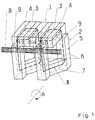
- FIG. 1 shows a Principle sketch of a part of a transverse flux machine for Explanation of the magnetic flux
- Fig. 2 the iron losses depending on the frequency and the magnetic permeability depending on the magnetic field strength for explanation the differences of magnetically isotropic material laminated sheets
- Fig. 3 shows an embodiment of the Pole elements of the stator of a transverse flux machine according to the invention in cross section
- Fig. 4a and 4b the design of the Poles of the laminated pole elements
- Fig. 5 the execution of the poles the pole elements in the form of magnetically isotropic material
- Fig. 7a and 7b two embodiments of the pole elements in Cross-section.
- Fig. 1 shows a three-dimensional section of a Transversal flux machine in the form of an external rotor (i.e. the rotating part of the machine is on the outside) for illustration of the magnetic flux.
- the outrunner are over the Scope of permanent magnets 3 in a number corresponding to the number of poles 2p of the machine and between the permanent magnets 3
- Flow guide pieces 4 made of magnetically conductive material.
- the axis of rotation of the machine is indicated by reference symbol A.
- the permanent magnets 3 are magnetized in the tangential direction.
- the permanent magnet 3 By marking the north pole N and south pole S the permanent magnet 3 illustrates the direction of magnetization.
- Magnetically conductive are on the stator 2 of the machine Pole elements 5 arranged, which are usually U-shaped or Comb shape in corresponding multi-phase transverse flux machines available.
- the web 7 runs between the legs 6 of the pole elements 5 is the winding 8, which is usually in the form of a ring winding is present, which is the magnetic field in the stator evokes.
- the magnetic flux ⁇ runs as in the illustration indicated in a three-dimensional form, whereby partially radially over the legs 6 of the pole elements 5 and transversely across the web 7 of the pole elements.
- Pole elements 5 made of laminated metal sheets are in the direction of Sheets have a high magnetic conductivity and therefore low Loss of iron causes, but normally you get a very low magnetic conductivity.
- the stray fields occur mainly between the pole elements 5 and on the poles 9 am Air gap between rotor 1 and stator 2.
- Fig. 2 shows the course of the iron losses depending the frequency for magnetic materials from sheet metal fins and made of sintered material.
- the top curve shows the iron losses for laminated sheet metal with a laminating direction transverse to the direction of the magnetic flux ⁇ , therefore the Iron losses relatively high.
- the bottom curve shows the iron losses for dynamo sheet with a lamination direction in Direction of the magnetic field lines. With such materials the iron losses are minimal.
- the losses with magnetically isotropic Materials such as are magnetic sintered materials independent of direction and are approximately between the size Losses for the two magnetization directions laminated sheets. Are the magnetic field lines only in on one level, the use of sheet metal is preferable. At the laminating direction is correct coincides with the field line level. However, with transverse flux machines, where the magnetic flux is not in one plane is the sum of the losses in sintered materials less.
- the mapping of the permeability ⁇ depending on the magnetic field strength H illustrates the properties of magnetic Sintered materials.
- Fig. 3 shows an embodiment of the pole elements 5 of the Stator 2, in which the parts of the pole elements 5, in which the magnetic flux transverse, i.e. parallel to the axis of rotation A runs, these are the webs 7 of the pole elements 5, made of magnetic Sintered material or magnetically isotropic material produced are.
- the parts of the pole elements 5, in which the magnetic flux ⁇ runs radially, that is the legs 6 of the Pole elements 5 can be made of soft magnetic material Lamination direction to be constructed normal to the axis of rotation A.
- FIG. 4a and 4b show an embodiment of the machine, in which the legs 6 of the pole elements 5 by laminated laminations are constructed, the poles 9 of the legs 6 of the pole elements 5 to enlarge the torque-generating surface are bent.
- a part can be used to make the machine easier to assemble the web 7 of the pole elements 5 also by laminated sheets be made so that the pole elements 5 of the stator 2 individual disks, as shown in Fig. 4a, are constructed.
- Fig. 5 shows an embodiment of the machine in which the Poles 9 are made of magnetically isotropic material.
- corresponding formations 10 can connect to the underlying Parts of the pole elements 5, which are the correct positioning of the poles 9 and a fixation, guaranteed in particular in the radial direction R.
- the pole elements 5 can also made entirely of magnetically isotropic material, in particular sintered material, be made. Especially in manufacturing almost any shape can be achieved by sintering, whereby the legs 6 of the pole elements 5 widen can be achieved, resulting in an increase in area, thus to a reduction in the magnetic induction B and to one Reduction of iron losses leads. Towards the end of the leg 6 of the Pole elements 5 must be tapered again, so that there is no magnetic short circuit on the rotor 1 arranged permanent magnets 3 and thus at all Torque generation is coming.
- the pole 9 Pole elements 5 grooves 11 are provided, which for Bandaging the arrangement when building the machine.
- Fig. 6b shows a variant in which the pole elements 5 of the entire machine made in one piece in the form of a ring are. Likewise, a certain number of pole elements 5 be made in one piece in the form of a ring segment and the entire machine is made up of some such ring segments become. In this case the individual parts are preferred provided with complementarily shaped formations 10, about the a tool-free connection possible without additional aids is. Such an embodiment is shown in Fig. 6c, at of the individual pole elements 5 with adjacent stator components and or or adjacent pole elements 5 are positively connected become.
- pole elements 5 damping inserts 12 for example made of rubber, arranged be used to isolate the pole elements 5 and to dampen or reduce the mechanical load by Vibrations between the individual pole elements 5 serve.
- the Pole shoe can also be constructed asymmetrically, as in Fig. 7b shown. This allows the magnetic flux to move in a preferred direction be directed. Since pole elements made of sintered material can take almost any shape is one Design relatively easy and inexpensive to achieve.
Abstract
Description
Die Erfindung betrifft eine Transversalflussmaschine mit über den Umfang des Rotors der Maschine angeordneten Permanentmagneten in einer Anzahl entsprechend der Polzahl der Maschine und allenfalls zwischen den Permanentmagneten angeordneten Flussleitstücken aus magnetisch leitfähigem Material, und mit über den Umfang des Stators der Maschine angeordneten Polelementen zur Aufnahme von Wicklungen zur Erzeugung eines magnetischen Flusses und zur Leitung des magnetischen Flusses.The invention relates to a transverse flux machine Permanent magnets arranged over the circumference of the rotor of the machine in a number corresponding to the number of poles of the machine and if necessary arranged between the permanent magnets Flux guides made of magnetically conductive material, and with pole elements arranged over the circumference of the stator of the machine to hold windings to generate a magnetic Flux and to guide the magnetic flux.
Transversalflussmaschinen zeichnen sich durch einen besonderen, dreidimensional verlaufenden, magnetischen Fluss aus, wobei im Gegensatz zu herkömmlichen elektrischen Maschinen magnetische Flusslinien auch in transversaler Richtung, d.h. parallel zur Drehachse der Maschine verlaufen, was auch zur Namensgebung dieser Maschinen geführt hat. Bei Transversalflussmaschinen wird mit Hilfe von Ringwicklungen am Stator ein magnetisches Feld erzeugt, welches über entsprechende Polelemente über den Luftspalt zum Rotor verläuft und dort mit Hilfe von Permanentmagneten und allenfalls Flussleitstücken konzentriert und in seiner Richtung geleitet wird. Üblicherweise sind die Polelemente am Stator aus weichmagnetischem Material aufgebaut. Häufig werden lamellierte Bleche mit einer Lamellierungsrichtung parallel zur Drehachse der Maschine verwendet. Die Polelemente weisen meist U-Form bei einphasigen Transversalflussmaschinen bzw. entsprechende Kammform bei mehrphasigen Transversalflussmaschinen auf, wobei zwischen den in Richtung des Rotors weisenden Schenkeln der Polelemente die Ringwicklung angeordnet ist. Zum leichteren Aufbau der Maschine können die Polelemente geteilt ausgeführt sein. Lamellierte Bleche weisen in Richtung der Ebene der Bleche eine sehr gute magnetische Leitfähigkeit auf, während sie normal zu der Ebene der Bleche eine sehr schlechte magnetische Leitfähigkeit zeigen. Dementsprechend ist beim dreidimensionalen Verlauf des magnetischen Flusses bei Transversalflussmaschinen in jenen Bereichen, wo die magnetischen Feldlinien normal zur Lamellierungsrichtung verlaufen, mit relativ hohen Eisenverlusten zu rechnen.Transverse flux machines are characterized by a special, three-dimensional magnetic flux, whereby in contrast to conventional electrical machines magnetic Flow lines also in the transverse direction, i.e. parallel run to the axis of rotation of the machine, which also gives the name of these machines. With transverse flux machines generates a magnetic field using ring windings on the stator, which has corresponding pole elements over the air gap runs to the rotor and there with the help of permanent magnets and at most, river guide pieces concentrated and in their direction is directed. The pole elements on the stator are usually made of soft magnetic material. Laminates are often used Sheets with a lamination direction parallel to the axis of rotation the machine used. The pole elements usually have a U shape single-phase transverse flux machines or corresponding comb shape in multi-phase transverse flux machines, with between the legs of the pole elements pointing in the direction of the rotor the ring winding is arranged. For easier assembly the pole elements of the machine can be divided. Laminated sheets point in the direction of the plane of the sheets very good magnetic conductivity while normal too the level of the sheets has a very poor magnetic conductivity demonstrate. Accordingly, the three-dimensional course of the magnetic flux in transverse flux machines in those Areas where the magnetic field lines are normal Lamination direction run, with relatively high iron losses to count.
Darüber hinaus sind die Streuverluste bei Transversalflussmaschinen zwischen den Polelementen des Stators und an den in Richtung des Rotors weisenden Enden der Polelemente relativ hoch.In addition, there are scatter losses in transverse flux machines between the pole elements of the stator and at the in Direction of the rotor facing ends of the pole elements relative high.
Ziel der vorliegenden Erfindung ist die Reduktion der magnetischen Verluste im Stator, sodass die Leistungsausbeute und der Wirkungsgrad der Maschine erhöht werden kann. Unter die magnetischen Verluste im Stator fallen insbesondere die Eisenverluste sowie die durch Streufelder hervorgerufenen Verluste.The aim of the present invention is to reduce the magnetic Losses in the stator, so that the power yield and the efficiency of the machine can be increased. Among the magnetic Losses in the stator fall in particular the iron losses as well as the losses caused by stray fields.
Die erfindungsgemäße Aufgabe wird dadurch gelöst, dass zumindest ein Teil der Polelemente des Stators der Maschine aus magnetisch isotropem Material besteht. Magnetisch isotrope Materialien haben in allen Richtungen gleiche magnetische Eigenschaften, im Gegensatz zu lamellierten Blechen, welche nur in Richtung der Blechebenen bevorzugte Eigenschaften aufweisen. Durch den Einsatz derartiger magnetisch isotroper Materialien können die Verluste entsprechend reduziert werden.The object of the invention is achieved in that at least part of the pole elements of the stator of the machine magnetically isotropic material. Magnetically isotropic materials have the same magnetic properties in all directions, in contrast to laminated sheets, which are only available in Have preferred properties in the direction of the sheet metal planes. By using such magnetically isotropic materials the losses can be reduced accordingly.
Vorzugsweise bestehen zumindest jene Teile der Polelemente des Stators der Maschine aus magnetisch isotropem Material, in welchen der magnetische Fluss von der radialen Richtung abweicht. Bei Verwendung lamellierter Bleche verläuft die Lamellierungsebene in der Regel in den radialer Richtung. Daher sollten insbesondere jene Bereiche, wo der magnetische Fluss normal auf die radiale Richtung bzw. die Lamellierungsebenen steht, also transversal, d.h. parallel zur Drehachse der Maschine oder tangential zur Drehachse der Maschine verläuft, aus magnetisch isotropem Material aufgebaut werden. Dadurch können in jenen Bereichen, die normalerweise sehr schlechte magnetische Leitfähigkeit bei der Verwendung von Blechpaketen aufweisen, die Verluste weiter reduziert werden und somit die Leistungsausbeute der Maschine erhöht werden.Preferably there are at least those parts of the pole elements the stator of the machine made of magnetically isotropic material, in which the magnetic flux deviates from the radial direction. If laminated sheets are used, this runs Lamellar plane usually in the radial direction. Therefore should particularly be those areas where the magnetic flux normal to the radial direction or the lamination levels stands, i.e. transversal, i.e. parallel to the axis of rotation of the machine or tangential to the axis of rotation of the machine, made of magnetic isotropic material. This allows in those areas that are usually very poor magnetic Have conductivity when using laminated cores that Losses can be further reduced and thus the power yield the machine can be increased.
Die aus magnetisch isotropem Material bestehenden Teile der Polelemente des Stators können aus magnetischem Sintermaterial bestehen. Diese Werkstoffe sind zwar zum gegenwärtigen Zeitpunkt noch teurer als lamellierte Bleche, jedoch ist die Herstellung, insbesondere komplizierterer Formen, durch Sintern wesentlich einfacher. Die Sintermaterialien bestehen aus Eisen-, Nickel- oder Kobaltpartikel, welche mit geeigneten Beschichtungen versehen sind und durch geeignete Bindematerialien miteinander verbunden werden.The parts of the magnetically isotropic material Pole elements of the stator can be made of magnetic sintered material consist. Although these materials are currently even more expensive than laminated sheets, but the production is especially more complex shapes, significantly sintered easier. The sintered materials consist of iron, nickel or cobalt particles, which with suitable coatings are provided and with each other by suitable binding materials get connected.
Gemäß einem weiteren Merkmal der Erfindung bestehen zumindest die im wesentlichen parallel zur Drehachse der Maschine verlaufenden Stege der Polelemente aus magnetisch isotropem Material. In diesen Stegen verläuft der magnetische Fluss transversal, d.h. parallel zur Drehachse der Maschine.According to a further feature of the invention at least essentially parallel to the axis of rotation of the machine extending ridges of the pole elements made of magnetically isotropic Material. The magnetic flux in these webs is transverse, i.e. parallel to the axis of rotation of the machine.
Gemäß einem weiteren Merkmal der Erfindung bestehen zumindest die Pole der im wesentlichen normal auf die Drehachse der Maschine stehenden Schenkel der Polelemente aus magnetisch isotropem Material. Auch in diesen Bereichen weist die Verwendung magnetisch isotroper Materialien Vorteile auf, da in diesen Bereichen die Flussrichtung dreidimensional ist und somit Verluste durch Streufelder zu erwarten sind.According to a further feature of the invention at least the poles of the substantially normal to the axis of rotation the machine standing leg of the pole elements made of magnetic isotropic material. Use in these areas also Magnetic isotropic materials have advantages because of these Areas the flow direction is three-dimensional and thus losses are to be expected from stray fields.
Gemäß einem weiteren Merkmal der Erfindung besteht ein Teil der Polelemente des Stators der Maschine aus lamellierten Blechen, wobei die Lamellierungsebene im wesentlichen normal zur Drehachse der Maschine steht. Durch eine derartige Kombination von magnetisch isotropem Material, insbesondere von Sintermaterial und lamellierten Blechen, können wesentliche Reduktionen der Verluste bewirkt werden, indem die Materialien an die jeweilige Richtung des magnetischen Flusses angepasst wird. Dementsprechend wird dort, wo der magnetische Fluss radial verläuft ein Dynamoblech und dort wo der magnetische Fluss transversal verläuft ein Sintermaterial eingesetzt. Die lamellierten Bleche weisen in Blechrichtung bessere magnetische Eigenschaften auf als die Sintermaterialien, jedoch dort, wo der magnetische Fluss seine Richtung ändert, d.h. im Übergangsbereich von radialer Richtung zu tangentialen Richtung, sind in Summe die Sintermaterialien vorzuziehen.According to another feature of the invention, there is a part the pole elements of the stator of the machine made of laminated sheets, the lamination plane being substantially normal to Axis of rotation of the machine is. With such a combination of magnetically isotropic material, especially sintered material and laminated sheets, can make significant reductions of the losses are caused by the materials to the respective direction of the magnetic flux is adjusted. Accordingly is where the magnetic flux is radial a dynamo sheet and where the magnetic flux is transverse runs a sintered material used. The laminated sheets have better magnetic properties in the direction of the sheet than the sintered materials, but where the magnetic flux changes its direction, i.e. in the transition area from radial Direction to tangential direction are the sintered materials preferable.
Vorteilhafterweise sind die zum Rotor der Maschine weisenden Schenkel der Polelemente sowie ein Teil der im wesentlichen parallel zur Drehachse der Maschine verlaufenden Stege der Polelemente des Stators durch lamellierte Bleche gebildet. Dadurch können die Verluste bedingt durch die Streuung im Bereich der Pole reduziert und die Eisenverluste im Bereich der Stege der Polelemente ebenfalls verringert werden. Zur besseren Herstellbarkeit ist ein Teil der im wesentlichen parallel zur Drehachse der Maschine verlaufenden Stege der Polelemente ebenfalls durch die Bleche gebildet, sodass die einzelnen in Richtung des Rotors weisenden Teile der Polelemente miteinander durch den Steg verbunden werden. Somit sind die Polelemente des Stators aus einzelnen scheibenförmigen Blechen aufgebaut, welche leicht durch Stanzwerkzeuge hergestellt werden können. Die scheibenförmigen Bleche werden vorteilhafterweise einmal entlang ihres Umfangs durchtrennt und allenfalls isoliert, sodass Probleme bedingt durch Wirbelströme vermieden werden können.Advantageously, those facing the rotor of the machine Leg of the pole elements as well as part of the essentially Ridges of the pole elements running parallel to the axis of rotation of the machine of the stator formed by laminated sheets. Thereby The losses can be caused by the spread in the area of Poles are reduced and the iron losses in the area of the webs Pole elements can also be reduced. For better Manufacturability is part of the essentially parallel to The axis of rotation of the machine extending webs of the pole elements also formed by the sheets, so that the individual in Parts of the pole elements pointing towards the rotor with one another be connected by the web. Thus, the pole elements of the Stator built from individual disc-shaped sheets, which can be easily manufactured by punching tools. The disk-shaped sheets are advantageously once along severed and possibly isolated, causing problems can be avoided due to eddy currents.
In diesem Fall können die in Richtung des Rotors der Maschine weisenden Pole der Polelemente an deren Enden zur Bildung von Polschuhen gebogen sein. Dabei sind die Bleche jeweils eines Blechpaketes in die gleiche Richtung gebogen, während die Bleche des nächsten benachbarten Blechpaketes in die Gegenrichtung gebogen sind. Dadurch entstehen sogenannte Polschuhe, welche eine Vergrößerung der momentenbildenden Oberfläche mit sich bringen und somit eine Drehmomentsteigerung. Darüber hinaus kann der magnetische Fluss durch die entsprechende Gestaltung des Blechpaketes in eine bevorzugte Richtung gelenkt werden und der Streufluss nach außen vermindert werden.In this case, the direction of the rotor of the machine facing poles of the pole elements at their ends for formation be bent by pole pieces. The sheets are one Sheet packets bent in the same direction while the sheets of the next adjacent laminated core is bent in the opposite direction are. This creates so-called pole shoes, which are Increase the torque-generating surface and thus an increase in torque. In addition, the magnetic Flow through the appropriate design of the laminated core be directed in a preferred direction and the Leakage flux to the outside can be reduced.
Gemäß einem weiteren Merkmal der Erfindung sind die lamellierten Bleche zu Blechpaketen zusammengefasst, welche gegeneinander, im wesentlichen um eine Polteilung oder ungeradzahlige Vielfache der Polteilung, verdreht sind. Die Polteilung ist definiert durch das Verhältnis des wirksamen Umfanges zwischen Rotor und Stator der Maschine zur Polzahl. Durch diese Verdrehung bzw. Versetzung der Polelemente können die üblicherweise verwendeten I-Joche am Rotor der Maschine zur Schließung der magnetischen Feldlinien entfallen, wodurch die Eisenverluste verringert und das resultierende Drehmoment und somit der Wirkungsgrad der Maschine erhöht werden können.According to a further feature of the invention, the laminated sheets combined to sheet packages, which against each other, essentially around a pole pitch or odd multiples of the pole pitch are twisted. The pole pitch is defined by the ratio of the effective scope between rotor and stator of the machine to the number of poles. By this rotation or displacement of the pole elements can Usually used i-yokes on the rotor of the machine Closure of the magnetic field lines is eliminated, which means that Iron losses are reduced and the resulting torque and thus the efficiency of the machine can be increased.
Zur leichteren Positionierung und Fixierung an den benachbarten Teilen des Stators weisen die aus magnetisch isotropem Material bestehenden Teile der Polelemente des Stators Ausformungen auf, welche in entsprechend komplementär gestaltete Ausformungen der benachbarten Teile des Stators eingreifen können. Dadurch kann insbesondere eine werkzeuglose und Verbindung ohne zusätzliche Hilfsmittel erreicht werden. Solche Ausformungen können widerhakenartig ausgebildet sein, sodass eine Verschiebung der Teile zueinander unterbunden werden kann.For easier positioning and fixing to the neighboring ones Parts of the stator are made of magnetically isotropic Material existing parts of the pole elements of the stator formations on, which in correspondingly complementary designs the adjacent parts of the stator can intervene. This allows in particular a tool-free and connection without additional aids can be achieved. Such forms can be barb-shaped, so that a shift the parts can be prevented from each other.
Bei der Verwendung von magnetisch isotropen Materialien, insbesondere von Sintermaterialien, können nahezu beliebige Gestaltungen der Polelemente erzielt werden, welche bei Verwendung von Blechen nicht möglich wären. Dementsprechend ist gemäß einem weiteren Merkmal der Erfindung vorgesehen, dass die gesamten Polelemente des Stators aus magnetisch isotropem Material bestehen. Dadurch kann eine Kostenreduktion gegenüber geblechten Varianten erzielt werden.When using magnetically isotropic materials, Sintered materials in particular can be of almost any design the pole elements can be achieved, which in use of sheet metal would not be possible. Accordingly, according to one Another feature of the invention provided that the entire Pole elements of the stator consist of magnetically isotropic material. This can reduce costs compared to laminated variants be achieved.
Wenn die Polelemente mehrstückig hergestellt sind, wobei die einzelnen Teile der Polelemente über komplementär gestaltete Ausformungen miteinander verbunden sind, kann eine einfache Herstellung erzielt werden.If the pole elements are made in several pieces, whereby the individual parts of the pole elements are designed to be complementary Formations are connected to each other, can be simple manufacture be achieved.
Insbesondere, wenn die Polelemente einstückig hergestellt werden, kann der Zusammenbau der üblicherweise aus einer sehr großen Anzahl von Einzelteilen bestehenden Transversalflussmaschinen erheblich erleichtert werden.Especially if the pole elements are made in one piece can be assembled from a very common large number of individual parts existing transverse flux machines be made considerably easier.
Gemäß einem weiteren Erfindungsmerkmal ist vorgesehen, dass die Schenkel und/oder Stege der Polelemente in Richtung des Rotors im wesentlichen keilförmig auseinanderlaufen und in Richtung der Pole zusammenlaufen. Durch die Verbreiterung der Schenkel resultiert eine größere Querschnittsfläche, wodurch in diesem Bereich die magnetische Induktion verringert und somit die Eisenverluste reduziert werden. An den Enden der Schenkel müssen die Pole wieder verjüngend ausgebildet werden, sodass die am Rotor gegenüberliegenden Permanentmagnete durch die Pole nicht magnetisch kurz geschlossen werden, was zu einer Reduktion bzw. Auslöschung des resultierenden Drehmomentes führen würde.According to a further feature of the invention, it is provided that the legs and / or webs of the pole elements in the direction of the rotor diverge essentially wedge-shaped and in the direction the Pole converge. By widening the legs results in a larger cross-sectional area, resulting in this Area the magnetic induction is reduced and thus the Iron losses can be reduced. At the ends of the legs the poles are tapered again, so that those on the rotor opposite permanent magnets through the poles not magnetic be closed briefly, which leads to a reduction or Extinction of the resulting torque would result.
Zwischen den Schenkeln der Polelemente können Dämpfungseinlagen aus elastischem Material, beispielsweise aus Gummi, angeordnet sein. Diese bringen eine Dämpfung bzw. Verringerung der mechanischen Belastung durch Vibrationen zwischen den einzelnen Polelementteilen mit sich und bewirkt darüber hinaus die notwendige Isolierung der einzelnen Polelemente. Damping inserts can be placed between the legs of the pole elements made of elastic material, such as rubber his. These bring a damping or reduction in mechanical stress due to vibrations between the individual Pole element parts with itself and also causes the necessary Isolation of the individual pole elements.
Diese und weitere Merkmale der Erfindung sind in den nachfolgenden Abbildungen näher erläutert. Darin zeigen Fig. 1 eine Prinzipskizze eines Teiles einer Transversalflussmaschine zur Erläuterung des magnetischen Flussverlaufes, Fig. 2 die Eisenverluste in Abhängigkeit der Frequenz und die magnetische Permeabilität in Abhängigkeit der magnetischen Feldstärke zur Erläuterung der Unterschiede von magnetisch isotropem Material zu lamellierten Blechen, Fig. 3 eine Ausführungsform der erfindungsgemäßen Polelemente des Stators einer Transversalflussmaschine im Querschnitt, Fig. 4a und 4b die Gestaltung der Pole der lamellierten Polelemente, Fig. 5 die Ausführung der Pole der Polelemente in Form von magnetisch isotropem Material, Fig. 6a bis 6c Ausführungsformen der Erfindung mit vollständig aus magnetisch isotropem Material hergestellten Polelementen, und Fig. 7a und 7b zwei Ausführungsformen der Polelemente im Querschnitt.These and other features of the invention are in the following Illustrations explained in more detail. 1 shows a Principle sketch of a part of a transverse flux machine for Explanation of the magnetic flux, Fig. 2 the iron losses depending on the frequency and the magnetic permeability depending on the magnetic field strength for explanation the differences of magnetically isotropic material laminated sheets, Fig. 3 shows an embodiment of the Pole elements of the stator of a transverse flux machine according to the invention in cross section, Fig. 4a and 4b the design of the Poles of the laminated pole elements, Fig. 5 the execution of the poles the pole elements in the form of magnetically isotropic material, 6a to 6c embodiments of the invention with complete pole elements made of magnetically isotropic material, and Fig. 7a and 7b two embodiments of the pole elements in Cross-section.
Fig. 1 zeigt einen dreidimensionalen Ausschnitt aus einer
Transversalflussmaschine in Form eines Außenläufers (d.h. der
rotierende Teil der Maschine liegt außen) zur Veranschaulichung
des magnetischen Flussverlaufes. Am Rotor 1 der Transversalflussmaschine,
in diesem Fall des Außenläufers, sind über den
Umfang Permanentmagnete 3 in einer Anzahl entsprechend der Polzahl
2p der Maschine und zwischen den Permanentmagneten 3
Flussleitstücke 4 aus magnetisch leitfähigem Material angeordnet.
Die Drehachse der Maschine ist mit Bezugszeichen A angedeutet.
In der gezeichneten Anordnung der abwechselnden
Permanentmagnete 3 und Flussleitstücke 4 am Rotor 1 der Maschine
sind die Permanentmagnete 3 in tangentialer Richtung magnetisiert.
Durch die Kennzeichnung des Nordpoles N und Südpoles S
der Permanentmagnete 3 wird die Magnetisierungsrichtung veranschaulicht.
Am Stator 2 der Maschine sind magnetisch leitfähige
Polelemente 5 angeordnet, welche üblicherweise in U-Form bzw.
Kammform bei entsprechend mehrphasigen Transversalflussmaschinen
vorliegen. Zwischen den radial angeordneten Schenkeln 6 der Polelemente
verläuft der Steg 7. Zwischen den Schenkeln 6 der Polelemente
5 ist die Wicklung 8, welche meist in Form einer Ringwicklung
vorliegt, angeordnet, welche das Magnetfeld im Stator
hervorruft. Der magnetische Fluss Φ verläuft, wie in der Darstellung
angedeutet, in einer dreidimensionalen Form, wobei
teilweise radial über die Schenkel 6 der Polelemente 5 sowie
transversal über den Steg 7 der Polelemente. Beim Aufbau der
Polelemente 5 aus lamellierten Blechen wird zwar in Richtung der
Bleche eine große magnetische Leitfähigkeit und somit geringe
Eisenverluste bewirkt, aber normal dazu erhält man eine sehr
niedrige magnetische Leitfähigkeit. Die Streufelder treten
hauptsächlich zwischen den Polelementen 5 und an den Polen 9 am
Luftspalt zwischen Rotor 1 und Stator 2 auf.Fig. 1 shows a three-dimensional section of a
Transversal flux machine in the form of an external rotor (i.e. the
rotating part of the machine is on the outside) for illustration
of the magnetic flux. At rotor 1 of the transverse flux machine,
in this case the outrunner are over the
Scope of
Fig. 2 zeigt den Verlauf der Eisenverluste in Abhängigkeit der Frequenz für magnetische Materialien aus Blechlamellen und aus Sintermaterial. Die oberste Kurvenform zeigt die Eisenverluste für lamelliertes Blech mit einer Lamellierungsrichtung quer zur Richtung des magnetischen Flusses Φ, daher sind die Eisenverluste relativ hoch. Die unterste Kurve zeigt die Eisenverluste für Dynamoblech mit einer Lamellierungsrichtung in Richtung der magnetischen Feldlinien. Bei derartigen Materialien sind die Eisenverluste minimal. Die Verluste bei magnetisch isotropen Materialien, wie z.B. magnetische Sinterwerkstoffen sind richtungsunabhängig und liegen größenmäßig etwa zwischen den Verlusten für die beiden Magnetisierungsrichtungen bei lamellierten Blechen. Liegen die magnetischen Feldlinien nur in einer Ebene vor, ist die Verwendung von Blechen vorzuziehen. Bei derartigen lamellierten Blechen stimmt die Lamellierungsrichtung mit der Feldlinienebene überein. Jedoch bei Transversalflussmaschinen, bei denen der magnetische Fluss nicht in einer Ebene liegt, sind in Summe gesehen die Verluste bei Sintermaterialien geringer. Die Abbildung der Permeabilität µ in Abhängigkeit der magnetischen Feldstärke H verdeutlicht die Eigenschaften von magnetischen Sintermaterialien.Fig. 2 shows the course of the iron losses depending the frequency for magnetic materials from sheet metal fins and made of sintered material. The top curve shows the iron losses for laminated sheet metal with a laminating direction transverse to the direction of the magnetic flux Φ, therefore the Iron losses relatively high. The bottom curve shows the iron losses for dynamo sheet with a lamination direction in Direction of the magnetic field lines. With such materials the iron losses are minimal. The losses with magnetically isotropic Materials such as are magnetic sintered materials independent of direction and are approximately between the size Losses for the two magnetization directions laminated sheets. Are the magnetic field lines only in on one level, the use of sheet metal is preferable. At the laminating direction is correct coincides with the field line level. However, with transverse flux machines, where the magnetic flux is not in one plane is the sum of the losses in sintered materials less. The mapping of the permeability µ depending on the magnetic field strength H illustrates the properties of magnetic Sintered materials.
Fig. 3 zeigt eine Ausführungsform der Polelemente 5 des
Stators 2, bei der die Teile der Polelemente 5, bei denen der
magnetische Fluss transversal, d.h. parallel zur Drehachse A
verläuft, das sind die Stege 7 der Polelemente 5, aus magnetischem
Sintermaterial bzw. magnetisch isotropem Material hergestellt
sind. Die Teile der Polelemente 5, bei denen der
magnetische Fluss Φ radial verläuft, das sind die Schenkel 6 der
Polelemente 5, können aus weichmagnetischem Material mit
Lamellierungsrichtung normal zur Drehachse A aufgebaut sein.Fig. 3 shows an embodiment of the
Fig. 4a und 4b zeigen eine Ausführungsform der Maschine,
bei der die Schenkel 6 der Polelemente 5 durch Blechlamellenpakete
aufgebaut sind, wobei die Pole 9 der Schenkel 6 der Polelemente
5 zur Vergrößerung der drehmomentenbildenden Oberfläche
verbogen sind. Zum leichteren Aufbau der Maschine kann ein Teil
des Steges 7 der Polelemente 5 ebenfalls durch lamellierte Bleche
hergestellt sein, sodass die Polelemente 5 des Stators 2 aus
einzelnen Scheiben, wie in Fig. 4a dargestellt, aufgebaut sind.4a and 4b show an embodiment of the machine,
in which the
Fig. 5 zeigt eine Ausführungsform der Maschine, bei der die
Pole 9 aus magnetisch isotropem Material hergestellt sind. Durch
entsprechende Ausformungen 10 kann eine Verbindung mit den darunterliegenden
Teilen der Polelemente 5 erfolgen, welche die
richtige Positionierung der Pole 9 und eine Fixierung,
insbesondere in radialer Richtung R gewährleistet.Fig. 5 shows an embodiment of the machine in which the
Wie in Fig. 6a dargestellt, können die Polelemente 5 auch
gesamt aus magnetisch isotropem Material, insbesondere Sintermaterial,
hergestellt sein. Insbesondere bei der Herstellung
durch Sintern können fast beliebige Gestaltungen erreicht werden,
wodurch eine Verbreiterung der Schenkel 6 der Polelemente 5
erreicht werden kann, was zu einer Vergrößerung der Fläche, somit
zu einer Reduktion der magnetischen Induktion B und zu einer
Reduktion der Eisenverluste führt. Gegen Ende der Schenkel 6 der
Polelemente 5 müssen diese wieder verjüngend ausgebildet sein,
sodass es nicht zu einem magnetischen Kurzschluss der am Rotor 1
angeordneten Permanentmagnete 3 und somit überhaupt zu einer
Drehmomentenbildung kommt. Darüber hinaus können am Pol 9 der
Polelemente 5 Nuten 11 vorgesehen werden, welche zur
Bandagierung der Anordnung beim Aufbau der Maschine dienen.As shown in Fig. 6a, the
Fig. 6b zeigt eine Variante, bei der die Polelemente 5 der
gesamten Maschine einstückig in Form eines Ringes hergestellt
sind. Ebenso können eine bestimmte Anzahl von Polelementen 5
einstückig in Form eines Ringsegmentes hergestellt werden und
die gesamte Maschine aus einigen derartigen Ringsegmenten aufgebaut
werden. In diesem Fall sind die Einzelteile vorzugsweise
mit komplementär gestalteten Ausformungen 10 versehen, über die
eine werkzeuglose Verbindung ohne zusätzliche Hilfsmittel möglich
ist. Eine derartige Ausführung ist in Fig. 6c gezeigt, bei
der die einzelnen Polelemente 5 mit angrenzenden Statorbauteilen
und bzw. oder angrenzenden Polelementen 5 formschlüssig verbunden
werden.Fig. 6b shows a variant in which the
Wie in Fig. 7a dargestellt, können zwischen den Polelementen
5 Dämpfungseinlagen 12, beispielsweise aus Gummi, angeordnet
sein, welche zu einer Isolierung der Polelemente 5 und
zur Dämpfung bzw. Verminderung der mechanischen Belastung durch
Vibrationen zwischen den einzelnen Polelementen 5 dienen. Der
Polschuh kann auch unsymmetrisch aufgebaut sein, wie in Fig. 7b
dargestellt. Dadurch kann der magnetische Fluss in eine Vorzugsrichtung
gelenkt werden. Da aus Sintermaterial hergestellte Polelemente
nahezu beliebige Formen annehmen können, ist eine derartige
Gestaltung relativ einfach und kostengünstig erzielbar.As shown in Fig. 7a, can between the
Claims (15)
Applications Claiming Priority (2)
| Application Number | Priority Date | Filing Date | Title |
|---|---|---|---|
| AT109899 | 1999-06-22 | ||
| AT0109899A AT504456A1 (en) | 1999-06-22 | 1999-06-22 | transverse flux |
Publications (3)
| Publication Number | Publication Date |
|---|---|
| EP1063754A2 true EP1063754A2 (en) | 2000-12-27 |
| EP1063754A3 EP1063754A3 (en) | 2003-11-05 |
| EP1063754B1 EP1063754B1 (en) | 2007-12-12 |
Family
ID=3506553
Family Applications (1)
| Application Number | Title | Priority Date | Filing Date |
|---|---|---|---|
| EP00890195A Expired - Lifetime EP1063754B1 (en) | 1999-06-22 | 2000-06-23 | Transversal flux machine |
Country Status (3)
| Country | Link |
|---|---|
| EP (1) | EP1063754B1 (en) |
| AT (2) | AT504456A1 (en) |
| DE (1) | DE50014837D1 (en) |
Cited By (17)
| Publication number | Priority date | Publication date | Assignee | Title |
|---|---|---|---|---|
| WO2003047067A3 (en) * | 2001-11-23 | 2003-08-21 | David Calley | Electrical machine |
| DE10240704A1 (en) * | 2002-09-04 | 2004-04-08 | Tirron-Elektronik Gmbh | High-pole alternator for back-geared motor torque/speed ranges, uses a frequency converter with higher frequencies and a much higher number of poles |
| WO2006126973A1 (en) * | 2005-05-26 | 2006-11-30 | Meier, Mojca | Stator comprising claw-shaped poles which are arranged on both sides |
| DE102008012324A1 (en) | 2008-03-03 | 2009-09-17 | Continental Automotive Gmbh | Electric machine e.g. harmonic machine, for use in magnetic levitation system, has pole elements designed, so that magnetic fluxes are circulated in pole elements, without passing into pole elements that are activated by electric conductors |
| US7605515B2 (en) | 2004-05-06 | 2009-10-20 | Gerard Koehler | Variable reluctance dynamo-electric rotary machine provided with united magnetic, electric and polarising circuits and method for production thereof |
| DE10262148B4 (en) * | 2002-09-04 | 2010-10-28 | Tirron-Elektronik Gmbh | High-pole alternator for back-geared motor torque/speed ranges, uses a frequency converter with higher frequencies and a much higher number of poles |
| EP2493054A1 (en) * | 2011-02-25 | 2012-08-29 | Siemens Aktiengesellschaft | Multi-phase transversal flow machine with inclined back iron segments |
| WO2012125790A2 (en) | 2011-03-15 | 2012-09-20 | Motor Excellence Llc | Transverse and/or commutated flux systems having laminated and powdered metal portions |
| EP2605367A1 (en) | 2011-12-12 | 2013-06-19 | Siemens Aktiengesellschaft | Transversal flux machine with Halbach arrays |
| CN103326487A (en) * | 2012-03-22 | 2013-09-25 | 通用汽车环球科技运作有限责任公司 | Segmented rotor in a rotor assembly |
| WO2015128072A3 (en) * | 2014-02-27 | 2016-07-07 | Sew-Eurodrive Gmbh & Co. Kg | Transverse flux machine |
| EP2641316A4 (en) * | 2010-11-17 | 2017-03-22 | Motor Excellence, LLC | Transverse and/or commutated flux systems having segmented stator laminations |
| US9722479B2 (en) | 2012-08-03 | 2017-08-01 | Eocycle Technologies Inc. | Wind turbine comprising a transverse flux electrical machine |
| US9876401B2 (en) | 2012-10-17 | 2018-01-23 | Eocycle Technologies Inc. | Transverse flux electrical machine rotor |
| WO2022035940A1 (en) * | 2020-08-12 | 2022-02-17 | Electric Torque Machines, Inc. | Electric motor |
| WO2022165029A1 (en) * | 2021-01-29 | 2022-08-04 | Electric Torque Machines, Inc. | Electric motor having laminas-formed teeth |
| US11831222B2 (en) | 2020-09-24 | 2023-11-28 | Electric Torque Machines, Inc. | Marine propeller system with high torque drive |
Families Citing this family (15)
| Publication number | Priority date | Publication date | Assignee | Title |
|---|---|---|---|---|
| US7973446B2 (en) | 2007-05-09 | 2011-07-05 | Motor Excellence, Llc | Electrical devices having tape wound core laminate rotor or stator elements |
| WO2008141198A1 (en) | 2007-05-09 | 2008-11-20 | Motor Excellence, Llc | Electrical output generating and driven devices using disk and non-disk shaped rotors, and methods of making and using the same |
| EP2255431B1 (en) | 2008-03-15 | 2012-05-16 | Rainer Marquardt | Low-inertia direct drive having high power density |
| WO2010062765A2 (en) | 2008-11-03 | 2010-06-03 | Motor Excellence, Llc | Transverse and/or commutated flux system rotor concepts |
| WO2011115632A1 (en) | 2010-03-15 | 2011-09-22 | Motor Excellence Llc | Transverse and/or commutated flux systems configured to provide reduced flux leakage, hysteresis loss reduction, and phase matching |
| CN102959832B (en) | 2010-03-15 | 2016-11-16 | 电扭矩机器股份有限公司 | There is the horizontal of phase deviation and/or commutation throughput systems |
| WO2011115633A1 (en) | 2010-03-15 | 2011-09-22 | Motor Excellence Llc | Transverse and/or commutated flux system for electric bicycles |
| DE102010018145B4 (en) | 2010-04-24 | 2012-07-26 | Kolektor Group D.O.O. | Claw pole type dynamoelectric machine |
| DE102010018146A1 (en) | 2010-04-24 | 2011-10-27 | Kolektor Group D.O.O. | Multiphase claw pole type dynamoelectric machine |
| WO2012067896A2 (en) | 2010-11-17 | 2012-05-24 | Motor Excellence, Llc | Transverse and/or commutated flux systems having laminated and powdered metal portions |
| WO2012067895A2 (en) | 2010-11-17 | 2012-05-24 | Motor Excellence, Llc | Transverse and/or commutated flux system coil concepts |
| US9559558B2 (en) | 2012-09-24 | 2017-01-31 | Eocycle Technologies Inc. | Modular transverse flux electrical machine assembly |
| DE102019215015A1 (en) * | 2019-09-30 | 2021-04-01 | Rolls-Royce Deutschland Ltd & Co Kg | Transverse flux machine |
| US11824410B1 (en) | 2023-01-11 | 2023-11-21 | Rolls-Royce Deutschland Ltd & Co Kg | Electrical machines for aircraft power and propulsion systems |
| US11827371B1 (en) | 2023-01-11 | 2023-11-28 | Rolls-Royce Deutschland Ltd & Co Kg | Electrical machines for aircraft power and propulsion systems |
Citations (4)
| Publication number | Priority date | Publication date | Assignee | Title |
|---|---|---|---|---|
| US5051641A (en) * | 1987-02-13 | 1991-09-24 | J. M. Voith Gmbh | Transversal flow machine in accumulator arrangement |
| EP0762618A1 (en) * | 1995-08-11 | 1997-03-12 | ROLLS-ROYCE POWER ENGINEERING plc | Electrical machine |
| DE19833021A1 (en) * | 1998-07-23 | 2000-01-27 | Voith Turbo Kg | Electrical machine stator e.g. for transversal flux machine, has peripheral surface provided by flux return element fitted with soft iron elements lying on either side of stator armature winding |
| US20020175586A1 (en) * | 1997-07-02 | 2002-11-28 | Wolfgang Hill | Electric machine with soft magnetic teeth |
-
1999
- 1999-06-22 AT AT0109899A patent/AT504456A1/en not_active Application Discontinuation
-
2000
- 2000-06-23 DE DE50014837T patent/DE50014837D1/en not_active Expired - Lifetime
- 2000-06-23 EP EP00890195A patent/EP1063754B1/en not_active Expired - Lifetime
- 2000-06-23 AT AT00890195T patent/ATE381140T1/en active
Patent Citations (4)
| Publication number | Priority date | Publication date | Assignee | Title |
|---|---|---|---|---|
| US5051641A (en) * | 1987-02-13 | 1991-09-24 | J. M. Voith Gmbh | Transversal flow machine in accumulator arrangement |
| EP0762618A1 (en) * | 1995-08-11 | 1997-03-12 | ROLLS-ROYCE POWER ENGINEERING plc | Electrical machine |
| US20020175586A1 (en) * | 1997-07-02 | 2002-11-28 | Wolfgang Hill | Electric machine with soft magnetic teeth |
| DE19833021A1 (en) * | 1998-07-23 | 2000-01-27 | Voith Turbo Kg | Electrical machine stator e.g. for transversal flux machine, has peripheral surface provided by flux return element fitted with soft iron elements lying on either side of stator armature winding |
Cited By (26)
| Publication number | Priority date | Publication date | Assignee | Title |
|---|---|---|---|---|
| US6664704B2 (en) * | 2001-11-23 | 2003-12-16 | David Gregory Calley | Electrical machine |
| US6924579B2 (en) * | 2001-11-23 | 2005-08-02 | David Calley | Electrical machine |
| WO2003047067A3 (en) * | 2001-11-23 | 2003-08-21 | David Calley | Electrical machine |
| DE10262148B4 (en) * | 2002-09-04 | 2010-10-28 | Tirron-Elektronik Gmbh | High-pole alternator for back-geared motor torque/speed ranges, uses a frequency converter with higher frequencies and a much higher number of poles |
| DE10240704A1 (en) * | 2002-09-04 | 2004-04-08 | Tirron-Elektronik Gmbh | High-pole alternator for back-geared motor torque/speed ranges, uses a frequency converter with higher frequencies and a much higher number of poles |
| DE10240704B4 (en) * | 2002-09-04 | 2006-04-27 | Tirron-Elektronik Gmbh | High-poled, multi-phase alternating current machine with transversal flux guidance |
| US7605515B2 (en) | 2004-05-06 | 2009-10-20 | Gerard Koehler | Variable reluctance dynamo-electric rotary machine provided with united magnetic, electric and polarising circuits and method for production thereof |
| WO2006126973A1 (en) * | 2005-05-26 | 2006-11-30 | Meier, Mojca | Stator comprising claw-shaped poles which are arranged on both sides |
| DE102008012324A1 (en) | 2008-03-03 | 2009-09-17 | Continental Automotive Gmbh | Electric machine e.g. harmonic machine, for use in magnetic levitation system, has pole elements designed, so that magnetic fluxes are circulated in pole elements, without passing into pole elements that are activated by electric conductors |
| EP2641316A4 (en) * | 2010-11-17 | 2017-03-22 | Motor Excellence, LLC | Transverse and/or commutated flux systems having segmented stator laminations |
| EP2493054A1 (en) * | 2011-02-25 | 2012-08-29 | Siemens Aktiengesellschaft | Multi-phase transversal flow machine with inclined back iron segments |
| WO2012113654A3 (en) * | 2011-02-25 | 2013-08-15 | Siemens Aktiengesellschaft | Multi-phase transverse flux machine having angled back irons |
| WO2012125790A2 (en) | 2011-03-15 | 2012-09-20 | Motor Excellence Llc | Transverse and/or commutated flux systems having laminated and powdered metal portions |
| EP2686939A2 (en) * | 2011-03-15 | 2014-01-22 | Motor Excellence, LLC | Transverse and/or commutated flux systems having laminated and powdered metal portions |
| EP2686939A4 (en) * | 2011-03-15 | 2014-10-29 | Electric Torque Machines Inc | Transverse and/or commutated flux systems having laminated and powdered metal portions |
| WO2013087412A1 (en) | 2011-12-12 | 2013-06-20 | Siemens Aktiengesellschaft | Transversal flux machine with halbach arrays |
| EP2605367A1 (en) | 2011-12-12 | 2013-06-19 | Siemens Aktiengesellschaft | Transversal flux machine with Halbach arrays |
| US20130249345A1 (en) * | 2012-03-22 | 2013-09-26 | GM Global Technology Operations LLC | Segmented rotor in a rotor assembly |
| CN103326487A (en) * | 2012-03-22 | 2013-09-25 | 通用汽车环球科技运作有限责任公司 | Segmented rotor in a rotor assembly |
| US9722479B2 (en) | 2012-08-03 | 2017-08-01 | Eocycle Technologies Inc. | Wind turbine comprising a transverse flux electrical machine |
| US9755492B2 (en) | 2012-08-03 | 2017-09-05 | Eocycle Technologies Inc. | Rotatable transverse flux electrical machine |
| US9876401B2 (en) | 2012-10-17 | 2018-01-23 | Eocycle Technologies Inc. | Transverse flux electrical machine rotor |
| WO2015128072A3 (en) * | 2014-02-27 | 2016-07-07 | Sew-Eurodrive Gmbh & Co. Kg | Transverse flux machine |
| WO2022035940A1 (en) * | 2020-08-12 | 2022-02-17 | Electric Torque Machines, Inc. | Electric motor |
| US11831222B2 (en) | 2020-09-24 | 2023-11-28 | Electric Torque Machines, Inc. | Marine propeller system with high torque drive |
| WO2022165029A1 (en) * | 2021-01-29 | 2022-08-04 | Electric Torque Machines, Inc. | Electric motor having laminas-formed teeth |
Also Published As
| Publication number | Publication date |
|---|---|
| AT504456A1 (en) | 2008-05-15 |
| EP1063754B1 (en) | 2007-12-12 |
| EP1063754A3 (en) | 2003-11-05 |
| ATE381140T1 (en) | 2007-12-15 |
| DE50014837D1 (en) | 2008-01-24 |
Similar Documents
| Publication | Publication Date | Title |
|---|---|---|
| EP1063754B1 (en) | Transversal flux machine | |
| DE102004036691B4 (en) | Rotor for a rotating machine of a reluctance type | |
| DE112015007131T5 (en) | Electric motor and air conditioning | |
| WO2007144232A1 (en) | Ring coil motor | |
| EP1005136A1 (en) | One-phase or multiphase transversal flux machine | |
| DE102013000222B4 (en) | Electric motor, comprising an iron core with primary teeth and secondary teeth | |
| DE102005047771A1 (en) | Rotor arrangement for electrical machine has stacked plates with some openings bridged at outer ends by outer bridges and other openings open at outer end | |
| DE102006000455A1 (en) | Internal permanent magnet rotor and internal permanent magnet motor | |
| DE102010024344A1 (en) | Direct current machine e.g. generator, has armature winding enclosing annular magnetic yoke as annular coil such that force- and movement effects occur between winding and permanent magnets or pole pieces | |
| DE102014101221A1 (en) | Rotor for a permanent magnet motor, method for manufacturing a rotor for a permanent magnet motor and permanent magnet motor | |
| DE102011118064A1 (en) | RUNNER AND MOTOR | |
| DE112009002090T5 (en) | Rotating electric machine | |
| DE102012219003A1 (en) | Rotor assembly for, e.g. rotary inner rotor permanent magnet machine, has pole piece held obliquely to radial direction extending web at rear end region while a web extends to magnetic yoke portion from radial center axis of pole piece | |
| DE102015104445A1 (en) | Electric motor with polygonal stand | |
| EP2587636A2 (en) | Electrical machine, in particular brushless torque motor | |
| DE102017102242A1 (en) | USE OF MAGNETIC FIELDS IN ELECTRIC MACHINES | |
| DE102013200476A1 (en) | Permanent magnet-excited two-pole synchronous machine e.g. wind force generator, for use as inner rotor machine in wind-power plant, has pockets comprising magnets that exhibits magnetization direction to form magnetic poles of rotor | |
| DE19900170A1 (en) | Permanent magnet motor | |
| DE102008022209A1 (en) | AC motor | |
| DE102008041604A1 (en) | Rotor for an electric machine with reduced cogging torque | |
| DE102019214434A1 (en) | Rotor of an electrical machine | |
| WO2013127435A1 (en) | Electric motor | |
| EP2705590B1 (en) | Rotor for a permanent-magnet machine | |
| DE102010036828A1 (en) | Annular stator for electro-dynamic machine, has U-shaped core metal sheets that are provided with two parallel legs for guiding magnetic flux within each coil | |
| DE102006011738A1 (en) | Electrical machine e.g. permanent magnet synchronize motor, has rotor supported around rotary axis in rotatable manner, where rotor has permanent magnets that are arranged within rotor and magnetic coating layer of magnetic pole |
Legal Events
| Date | Code | Title | Description |
|---|---|---|---|
| PUAI | Public reference made under article 153(3) epc to a published international application that has entered the european phase |
Free format text: ORIGINAL CODE: 0009012 |
|
| AK | Designated contracting states |
Kind code of ref document: A2 Designated state(s): AT BE CH CY DE DK ES FI FR GB GR IE IT LI LU MC NL PT SE |
|
| AX | Request for extension of the european patent |
Free format text: AL;LT;LV;MK;RO;SI |
|
| RAP1 | Party data changed (applicant data changed or rights of an application transferred) |
Owner name: BOMBARDIER TRANSPORTATION GMBH |
|
| PUAL | Search report despatched |
Free format text: ORIGINAL CODE: 0009013 |
|
| AK | Designated contracting states |
Kind code of ref document: A3 Designated state(s): AT BE CH CY DE DK ES FI FR GB GR IE IT LI LU MC NL PT SE |
|
| AX | Request for extension of the european patent |
Extension state: AL LT LV MK RO SI |
|
| 17P | Request for examination filed |
Effective date: 20040403 |
|
| AKX | Designation fees paid |
Designated state(s): AT DE FR GB |
|
| 17Q | First examination report despatched |
Effective date: 20061204 |
|
| GRAP | Despatch of communication of intention to grant a patent |
Free format text: ORIGINAL CODE: EPIDOSNIGR1 |
|
| GRAS | Grant fee paid |
Free format text: ORIGINAL CODE: EPIDOSNIGR3 |
|
| GRAA | (expected) grant |
Free format text: ORIGINAL CODE: 0009210 |
|
| AK | Designated contracting states |
Kind code of ref document: B1 Designated state(s): AT DE FR GB |
|
| REG | Reference to a national code |
Ref country code: GB Ref legal event code: FG4D Free format text: NOT ENGLISH |
|
| RIN1 | Information on inventor provided before grant (corrected) |
Inventor name: SCHAEFER, UWE Inventor name: STOCKMAYER, MICHAEL Inventor name: HACKMANN, WILHELM Inventor name: GUENTENSPERGER, WALTER Inventor name: NEUDORFER, HARALD |
|
| REF | Corresponds to: |
Ref document number: 50014837 Country of ref document: DE Date of ref document: 20080124 Kind code of ref document: P |
|
| GBT | Gb: translation of ep patent filed (gb section 77(6)(a)/1977) |
Effective date: 20080227 |
|
| ET | Fr: translation filed | ||
| PLBE | No opposition filed within time limit |
Free format text: ORIGINAL CODE: 0009261 |
|
| STAA | Information on the status of an ep patent application or granted ep patent |
Free format text: STATUS: NO OPPOSITION FILED WITHIN TIME LIMIT |
|
| 26N | No opposition filed |
Effective date: 20080915 |
|
| PGFP | Annual fee paid to national office [announced via postgrant information from national office to epo] |
Ref country code: AT Payment date: 20120613 Year of fee payment: 13 |
|
| PGFP | Annual fee paid to national office [announced via postgrant information from national office to epo] |
Ref country code: DE Payment date: 20130620 Year of fee payment: 14 Ref country code: GB Payment date: 20130619 Year of fee payment: 14 |
|
| PGFP | Annual fee paid to national office [announced via postgrant information from national office to epo] |
Ref country code: FR Payment date: 20130703 Year of fee payment: 14 |
|
| REG | Reference to a national code |
Ref country code: DE Ref legal event code: R119 Ref document number: 50014837 Country of ref document: DE |
|
| REG | Reference to a national code |
Ref country code: AT Ref legal event code: MM01 Ref document number: 381140 Country of ref document: AT Kind code of ref document: T Effective date: 20140623 |
|
| GBPC | Gb: european patent ceased through non-payment of renewal fee |
Effective date: 20140623 |
|
| REG | Reference to a national code |
Ref country code: DE Ref legal event code: R119 Ref document number: 50014837 Country of ref document: DE Effective date: 20150101 |
|
| REG | Reference to a national code |
Ref country code: FR Ref legal event code: ST Effective date: 20150227 |
|
| PG25 | Lapsed in a contracting state [announced via postgrant information from national office to epo] |
Ref country code: DE Free format text: LAPSE BECAUSE OF NON-PAYMENT OF DUE FEES Effective date: 20150101 |
|
| PG25 | Lapsed in a contracting state [announced via postgrant information from national office to epo] |
Ref country code: GB Free format text: LAPSE BECAUSE OF NON-PAYMENT OF DUE FEES Effective date: 20140623 Ref country code: FR Free format text: LAPSE BECAUSE OF NON-PAYMENT OF DUE FEES Effective date: 20140630 Ref country code: AT Free format text: LAPSE BECAUSE OF NON-PAYMENT OF DUE FEES Effective date: 20140623 |