EP1062975A2 - Cardio-electrical device - Google Patents
Cardio-electrical device Download PDFInfo
- Publication number
- EP1062975A2 EP1062975A2 EP00250208A EP00250208A EP1062975A2 EP 1062975 A2 EP1062975 A2 EP 1062975A2 EP 00250208 A EP00250208 A EP 00250208A EP 00250208 A EP00250208 A EP 00250208A EP 1062975 A2 EP1062975 A2 EP 1062975A2
- Authority
- EP
- European Patent Office
- Prior art keywords
- parameters
- tachycardia
- apd
- values
- memory
- Prior art date
- Legal status (The legal status is an assumption and is not a legal conclusion. Google has not performed a legal analysis and makes no representation as to the accuracy of the status listed.)
- Granted
Links
Images


Classifications
-
- A—HUMAN NECESSITIES
- A61—MEDICAL OR VETERINARY SCIENCE; HYGIENE
- A61N—ELECTROTHERAPY; MAGNETOTHERAPY; RADIATION THERAPY; ULTRASOUND THERAPY
- A61N1/00—Electrotherapy; Circuits therefor
- A61N1/18—Applying electric currents by contact electrodes
- A61N1/32—Applying electric currents by contact electrodes alternating or intermittent currents
- A61N1/36—Applying electric currents by contact electrodes alternating or intermittent currents for stimulation
- A61N1/362—Heart stimulators
- A61N1/365—Heart stimulators controlled by a physiological parameter, e.g. heart potential
- A61N1/36585—Heart stimulators controlled by a physiological parameter, e.g. heart potential controlled by two or more physical parameters
-
- A—HUMAN NECESSITIES
- A61—MEDICAL OR VETERINARY SCIENCE; HYGIENE
- A61N—ELECTROTHERAPY; MAGNETOTHERAPY; RADIATION THERAPY; ULTRASOUND THERAPY
- A61N1/00—Electrotherapy; Circuits therefor
- A61N1/18—Applying electric currents by contact electrodes
- A61N1/32—Applying electric currents by contact electrodes alternating or intermittent currents
- A61N1/36—Applying electric currents by contact electrodes alternating or intermittent currents for stimulation
- A61N1/362—Heart stimulators
- A61N1/37—Monitoring; Protecting
- A61N1/3702—Physiological parameters
-
- A—HUMAN NECESSITIES
- A61—MEDICAL OR VETERINARY SCIENCE; HYGIENE
- A61N—ELECTROTHERAPY; MAGNETOTHERAPY; RADIATION THERAPY; ULTRASOUND THERAPY
- A61N1/00—Electrotherapy; Circuits therefor
- A61N1/18—Applying electric currents by contact electrodes
- A61N1/32—Applying electric currents by contact electrodes alternating or intermittent currents
- A61N1/38—Applying electric currents by contact electrodes alternating or intermittent currents for producing shock effects
- A61N1/39—Heart defibrillators
- A61N1/3925—Monitoring; Protecting
Definitions
- the invention relates to a device for a tachycardia of a heart.
- a heart especially a human heart, can be physiologically questionable and possibly fatal conditions.
- a condition is a so-called Tachycardia, which is characterized by very rapid successive heartbeats, i.e. one high heart rate with reduced pumping power of the heart.
- Cardioverters or defibrillators are generally known.
- a disadvantage of the known Device is that they only recognize tachycardia when if it has already occurred.
- Such a device is indeed capable of causing impending tachycardia recognize before it enters. Deriving the heart descriptively, more time variant Parameters from the measured value pairs will be described in detail below. Determining the heart rate, i.e. the heart's pulse rate, and the duration of the action potential is generally known per se, as evidenced by the following description also results. It is also known in principle as a device must be designed so that it is able to determine whether certain Parameters fall within a certain parameter range.
- a device which is used to record at least two pairs of measured values is formed at different times and additionally a second Memory that is connected to the measured value processing means and in which at least the parameters derived for the two most recent measurement times can be stored are included, and trend determining means connected to the second memory and are used to determine a trend for the future development of the parameters are formed on the basis of the stored parameters, the evaluation unit is connected to the trend determining means and is designed to generate the tachycardia hazard signal outputs if the derived parameters are close to the tachycardia hazard area lie and the trend for the future development of the parameters points towards the tachycardia hazard area.
- Such a device is able to detect a risk of tachycardia before the determined parameters in fall within an area known to be dangerous, since the device has already determined beforehand can that the derived from the pairs of measured values in the direction of Develop danger area.
- an alternatively preferred device which is for recording at least two pairs of measured values is formed at different measuring times and additionally a second memory, which is connected to the measured value processing means and at least for the two most recent measurement times derived parameters are storable, includes, and trend determining means, the are connected to the second memory and for extrapolating future parameters are formed from the stored parameters, the evaluation unit connected to the trend determining means and to compare the extrapolated Parameters with comparison values stored in the memory and for outputting a Tachycardia hazard signal are formed if the comparison of the extrapolated Parameter with the comparison values shows that the extrapolated parameters in the Tachycardia hazard area.
- these parameters are suitable to describe the properties of cardiac muscle cells so that a early tachycardia detection is possible.
- the above-described situation can also be expressed in such a way that the first parameter ( ⁇ x ) is the time constant of the dynamic potassium channel of the heart muscle cells and the second parameter (g) is the ratio ((A Ca - A KI ) / (A Kx ) ) between the permeabilities of the calcium channel (A Ca ) and the static potassium channel (A KI ) and the dynamic potassium channel (A Kx ) of the heart muscle cells.
- a device which additionally has an electrostimulator such as is particularly preferred has a cardioverter or a defibrillator, and which is characterized by that the electrostimulator with evaluation unit for taking over the tachycardia hazard signal connected and by the tachycardia hazard signal to deliver anti-tachycardia electrical stimulation pulses to the heart is designed to be triggered.
- Fig. 1 shows a device for the early detection of a Tachycardia of a heart.
- This device 10 comprises an electrode line 12 which is used to receive electrical Signals of a heart 14 is connected to a measuring unit 16.
- the measuring means 16 derive measured values for the heart rate HR from the recorded electrical signals Heart 14 or the reciprocal of the heart rate HR, the cycle length L on the one hand and on the other hand, measured values for the depolarization time T or the action potential duration APD of the heart. These measured values are determined at different times and forwarded in pairs to one another to a measured value processing unit 18.
- the measured value processing unit 18 is provided with corresponding ones on the input side Outputs of the measuring unit 16 connected.
- the cycle length L a time constant ⁇ x of the dynamic potassium channel of the heart muscle cells of the heart 14 and a difference g of the calcium current amplitude A Ca and the potassium current amplitude A KI based on the amplitude of the dynamic potassium current A Kx .
- the difference g represents the ratios of the permeabilities of the calcium and potassium channels.
- the derived parameters ⁇ x and g are forwarded by the measured value processing unit 18 as mutually assigned value pairs to an evaluation unit 20 which is connected on the input side to the output of the measured value processing unit 18.
- the evaluation unit 20 is connected to a first memory 22 and a second memory 24, which can form a physical unit.
- comparison values for the parameters ⁇ x and g are stored which identify a danger zone or a tachycardia danger area, ie comparison values for those value pairs of the parameters ⁇ x and g which indicate a risk of tachycardia.
- the evaluation unit 20 is designed such that it compares the derived values for the parameters ⁇ x and g received from the measured value processing unit 18 with the comparison values stored in the first memory 22 and outputs a tachycardia hazard signal if the comparison should show that Values for the parameters ⁇ x and g transmitted to the measured value processing unit fall into the danger zone or the tachycardia danger area.
- Value pairs for values of the parameters ⁇ x and g derived at earlier measurement times are stored in the second memory 24.
- the evaluation unit 20 determines a trend for future values of the parameters ⁇ x and g. If this trend points in the direction of such values of ⁇ x and g that lie in the danger zone or the tachycardia danger area, the evaluation unit 20 also outputs a tachycardia danger signal if the values of these parameters last transmitted by the measured value processing unit are not in the danger zone.
- the evaluation unit 20 determines extrapolated values for the parameters ⁇ x and g for the future from the values for ⁇ x and g last transmitted by the measured value processing unit and the values of previous measurement times stored in the second memory 24. If these extrapolated parameter values lie in the tachycardia risk area, the evaluation unit 20 likewise outputs a tachycardia risk signal.
- the tachycardia hazard signal is forwarded to an electrostimulation unit 26, which is connected to the evaluation unit 20 for this purpose.
- the electrostimulation unit 26 can be an electrical stimulator, such as a cardioverter or a Defibrillator.
- the electrical stimulation unit 26 is via an electrical line with electrically conductive surface areas of the electrode lead inserted into the heart 14 12 connected to over the electrically conductive surface areas on the Electrode line 12 to the heart 14 in a manner known per se and to combat tachycardia.
- the electrode line 12 can be connected to the device in a manner known per se 10 connected that to the conductive surface areas, for example can be designed as a ring or tip electrode, leading lines are switchable so that the electrically conductive surface areas on the one hand Delivering stimulation pulses to the heart 14 and on the other hand for recording electrical signals from the heart 14 can be switched.
- the switching state is the electrically conductive surface areas with the measuring unit 16 connected to supply electrical signals to the heart.
- In another Switching state are the electrically conductive surface areas with the Electrostimulation unit 26 connected to electrical stimulation pulses to the To give up heart 14.
- the subject of the considerations is the myocardial syncytium, which turns out to be a manifested nonlinear dynamic system.
- the goal is based on methods the system identification to define and quantify parameters Characterize arrhythmia-relevant properties of the syncytium.
- For Implementation of the system identification must know the input and output signal with the input signal deflecting the system, i.e. the internal State variables must stimulate.
- the concrete choice of input and output signal is based on physiological criteria, which will be discussed later. If the system is observable in the system-theoretical sense, it can be used the system parameters are determined based on the transmission behavior. In the specific case can this requirement be somewhat restricted to the extent that the system (only) must be observable with regard to the arrhythmia-relevant parameters.
- the extended approach presented in this work builds on one physiologically based model of the substrate.
- the modeling directed to the fact that, in particular, those relevant to arrhythmia from a physiological point of view Parameters are worked out.
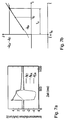
- the starting point is a mathematical one Model of the cardiac muscle cell, which on the one hand acts as a network node in muscle tissue is to be considered and, on the other hand, via the dynamically acting ion channels Ion flow between the intracellular and extracellular space enables (Fig. 2).
- the repolarization time represents the time interval between the time of excitation of the cell and the time of return to the resting membrane potential, ie the duration of the action potential (APD, here representative of APD 90 ). Strictly speaking, however, it is a parameter that characterizes the individual cell.
- HR as local heart rate
- the correlation between the action potential duration and, for example, the QT interval of the ECG has been demonstrated both experimentally and theoretically in good approximation. Similar considerations also apply to the IEGM, XAP or VER , so that several alternatives are available for the metrological determination of an approximate value of the repolarization time. Which of the two is the cheapest must still be decided on the basis of practical aspects of clinical implementation and the computational complexity of signal processing. However, it should be noted that both the input signal as well as the output signal can be measured as necessary prerequisites for system identification with reasonable technical effort.
- Fig. 3a which shows the entire settling process as a result of the frequency jump
- the restitution curve is obtained if the peak values are connected immediately after the jump.
- the APD ( HR ) results ⁇ curve if the mean values of the APD times are plotted at a later point in time.
- the relationship between repolarization time and heart rate is derived from the mathematical model description of the heart muscle cell.
- the goal is to determine the APD ( HR )
- the cell embodies a rigid dynamic System. While the time constants of the fast state variables compared to APD are vanishingly small, the gate variables f and in particular x even long after the action potential returns to the resting membrane voltage not their steady state.
- the variable f describes the Opening state of the inactivation gate of the Ca channel and x the opening state of the dynamic K channel. Both variables vary between 0 and 1 (relative State of opening).
- the new stimulus starts earlier, so that the initial values of the state variables f and x for the new cycle differ significantly from those of the previous cycle. It is therefore obvious that corresponding changes in the characteristic Dimensions of the action potential are to be expected.
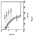
- the initial value is concrete of x larger in this example case (Fig. 4), i.e. the K current already starts from an increased value. With this, the unstable equilibrium of ion currents during the plateau phase earlier towards a repolarizing outward cell current tilted; the duration of the action potential is shortened. Similar considerations can be made for the Ca channel. With a shortened stimulation period, the f-variable is still noticeably less than 1, i.e. the Ca channel cannot yet be fully activated.
- Fig. 5 illustrates these effects using a Simulation calculation.
- V m 0 and A V denote the quiescent membrane voltage and the amplitude of the action potential, s ( t ) is the Heaviside jump function.
- y ⁇ only takes on 2 values, namely y s during systole (excited state) and y d during diastole (unexcited state), so that the differential equation from (1) becomes linear within each of these two time intervals. In some areas, y (t) then has an exponential course.
- Y is an example of an approximation of the gate variable x (note the Agreement with Fig. 4).
- the repolarization time is represented by the action potential duration, which is referred to as T in the calculations for the sake of simplicity.
- T the action potential duration
- L stimulation period
- ⁇ the duration of the diastole
- y n ( y n -1 - y s ) e - L n -1 ⁇ + ( y s - y d ) e - L n -1 - T n -1 ⁇ + y d
- the next step is to relate these state variables to the action potential duration be derived. To do this, it is helpful to see the timeline of the most important ones Analyze ion currents of the cell model to provide a mathematical criterion for define the triggering of the repolarization in the action potential.
- the ion currents relevant in relation to the repolarization are the Ca current, and the currents through the dynamic and the static K channel, the sum of which current is directed outward of the cell during the repolarization phase. They are included in the calculation in the form of the current densities J Ca , J Kx and J KI .
- the Na current is negligible because it is almost 0 except during depolarization.
- J Kx alone is still temporally variable during the plateau phase and therefore determines when the current direction changes.
- the scope of this description (8) is limited to the plateau phase (diastole). That due to this simplified representation of the ion currents the total current and thus dV m / dt during the plateau phase is not equal to 0, ie the action potential plateau cannot be strictly speaking (as described by equation (2)) must be accepted as a consequence of these simplifications .
- the duration (pulse width) of the action potential is of interest and not the exact signal morphology.
- This mathematical model representation represents an important partial result for the desired system identification, the equations of which express the nonlinear dynamic relationship between the state variables: action potential duration (T) and the gate variables x and f.
- the input signal of the system is the cycle length L.
- the most important variables with regard to the early detection of arrhythmias are the model parameters ⁇ x , c 1 and c 0 .
- ⁇ x represents the time constant of the dynamic K channel, while c 1 and c 0, as defined in (10 b, c), express the ratios of the Ca and K current amplitudes.
- the latter are a measure of the conductivity of the relevant ion channels and provide information about their operating points.
- the system is viewed in a steady state, that is, when it has been stimulated at a constant frequency for a long time, so that transient processes are completed.
- Parameters of this relationship are ⁇ x the time constant of the dynamic K-channel, and g , an expression that describes the relationships between the permeabilities of the Ca and the K-channels on the basis of (14) and (10 b, c).
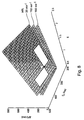
- FIG. 8 illustrates the dependency of the action potential duration T on the physiological parameters ⁇ x and g in the form of a pair of surfaces, whose pair parameter is the stimulation frequency.
- P 0 ( ⁇ x 0 , g 0 )
- a linearized description approximates this relationship to a good approximation.
- This fact justifies linearization in the following relationship (23) with regard to the parameters ⁇ x and g . Then their values can be calculated based on a linear system of equations.
- T 0 ( L ) ⁇ x 0 m 1 e 2nd L ⁇ x 0 + m 2nd e L ⁇ x 0 + m 3rd G 0 e L ⁇ x 0 + m 4th G 0 + m 5 + m 6 e L ⁇ x 0 + m 7
- the relationship between the action potential duration and the cycle length is: T ( L , ⁇ x , G ) ⁇ T 0 ( L ) + ⁇ T ⁇ x
- this relationship forms the basis for the development of an algorithm for determining the parameters ⁇ x and g , that is to say the quantities which provide information about the functional state of the Ca and K channels with regard to an impending arrhythmia.
- the time intervals during which the measured value pairs ( L m , T m ) are recorded should be selected so that a steady state is present as well as possible. Although this can easily be determined from the variability of the heart rate, as the simulation results presented later show, it is sufficient if the measured variables do not change all too suddenly (rate of change of the heart rate ⁇ 10 bpm / heartbeat) in order to nevertheless obtain good results .
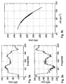
- FIGS. 9a, 9b and 9c visualize an application example of this parameter estimation algorithm.
- 9a and 9b firstly show the heart rate (HR) (here representative of L), for which a random but physiologically acceptable course was assumed in the simulation.
- HR heart rate
- T repolarization time
- the behavior was given a deterministic Heart rate curve tested in the form of a ramp between 60 bpm and 80 bpm. In the In practice, this means that the pacemaker has such a stimulation protocol must follow to deflect the system. Under these conditions the parameter recalculation is characterized by relative errors below 2%, while mostly only 3 iterations are needed.
- the simulation results showed that even with stochastic heart rate profiles, that come close to natural, still usable results. It is therefore not absolutely necessary to identify a specific system rigidly follow the specified stimulation protocol, which may even be the does not meet current needs of the organism.
- the implant fulfills in In this sense, the role of a diagnostic observer and prompted a therapeutic measure only if necessary.
- a cell model serves as the test object (system to be identified) (based on [[6]]), the state variables of which are directly physiological variables depict. This makes it possible to directly identify pathological system behavior simulation of clinical studies.
- FIGS. 10 and 11 illustrate this relationship for the now physiological cell model using two stimulation protocols.
- 11a and 11b similar to FIGS. 3a and 3b, show the system's response to a sudden change in the stimulation frequency.
- the measured value pairs (HR, APD) (corresponding to (27)) were plotted as points (groups consisting of several measured value pairs for the stimulation frequency after the jump).
- the solid line represents the APD ( HR )
- 11b illustrates the transient process itself: on the one hand for the physiological cell model and on the other hand for the replacement model.
- the parameter values ( ⁇ x , g ) required for the replacement model were calculated back from the measurements on the physiological model.
- 11b illustrates in particular how detailed the replacement model itself simulates the transient process, that is, despite simplifications, also has a physiologically correct behavior in quantitative terms.
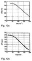
- FIGS. 12a and 12b show that among others Framework conditions, the replacement model behaves correctly physiologically. This one The protocol used sets a ramp to excite the system increasing course of the stimulation frequency. Regarding the illustrated Sizes are analogous to FIGS. 11a, 11b and 12a, 12b.
- the developed method should also be able to detect changes in the substrate properties. This ability was tested using the physiological cell model, specifically modifying the permeability of the Ca channel and / or shifting the relaxation characteristic ⁇ x ( Vm ) of the dynamic K channel along the abscissa.
- the table summarizes the quantities which, on the one hand, describe the changes in the ion channels and, on the other hand, reflect the system parameters ( ⁇ x , g ) determined from the simulated measurements.
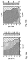
- FIGS. 14a and 14b The coupling of the identified system parameters ( ⁇ x , g ) emerges particularly well from FIGS. 14a and 14b, since the contour lines do not run parallel to either of the two parameter axes.
- These graphics represent the relationship between the system parameters ⁇ x and g in the variation area of the cellular model parameters Ca_mod and taux_sh.
- the interval limits within which the parameters of the physiological cell model were varied can be read from FIGS. 14a and 14b.
- the grid was 11 subdivisions per parameter area. For the parameter estimation, 100 stimulation cycles were considered (for each grid point).
- the cell model behaves pathologically for parameter values (Ca_mod, taux_sh) within the areas hatched in FIGS. 14a and 14b; EADs occur. Since in this extreme case the model considerations for deriving the mathematical relationship between APD and HR are no longer valid, the use of the method developed from this for parameter estimation in this area is also inadmissible. Therefore, no values for ⁇ x and g can be specified in the hatched area. In Fig. 14a, however, it is striking that the steepest gradient of g points exactly in the direction of this danger zone.
- the mechanisms and cellular causes of arrhythmogenesis are complex and changed substrate properties can cause tachycardia in a wide variety of ways Trigger way.
- Trigger way the relationship between the Occurrence of EADs and the Reenty-based arrhythmia form 'Torsade de Pointes' proven [[10]] [[11]].
- these mechanisms are also in one Model study has been clarified and reproduced [[13]]. That concludes the Chain of arguments as to why this method is also used for the early detection of Tachycardia is applicable.
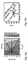
- 15b shows the image of these trajectories in the parameter space ( ⁇ x , g ).
- the boundary points of the hatched EAD area from the illustration on the left were transformed into this parameter space and a regression line was drawn through these points. It represents the boundary to the EAD zone in the parameter space.
- another straight line is laid parallel to it, which marks the danger zone. If the operating point ( ⁇ x, g ) moves beyond this limit, the algorithm sets an alarm flag.
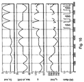
- 17a and 17b provide a more detailed insight.
- two examples illustrates how the procedure is about 100 heartbeats before the onset of the EADs recognizes and reports this danger.
- the exact number of heartbeats depends on However, depending on the speed at which the Change substrate properties. However, it can be assumed with great certainty that that a disease does not suddenly occur from one heartbeat to another, but rather progresses gradually. As expected, this is the case in practice sufficient time for therapeutic measures.
- the method can even use the identified system parameters to determine what the EADs will look like in a specific case. Indications of EADs are also provided by the parameter g alone, the gradient of which is steepest in the direction of the danger zone (FIGS. 14a and 14b). However, the expected EAD forms can only be specified with the help of the parameter ⁇ x .
Abstract
Description
Die Erfindung betrifft eine Vorrichtung einer Tachykardie eines Herzens.The invention relates to a device for a tachycardia of a heart.
Ein Herz, insbesondere ein menschliches Herz, kann in physiologisch bedenkliche und möglicherweise tödliche Zustände geraten. Ein solcher Zustand ist eine sogenannte Tachykardie, die sich durch sehr schnell aufeinanderfolgende Herzschläge, also eine hohe Herzrate bei gleichzeitig verminderter Pumpleistung des Herzens auszeichnet.A heart, especially a human heart, can be physiologically questionable and possibly fatal conditions. Such a condition is a so-called Tachycardia, which is characterized by very rapid successive heartbeats, i.e. one high heart rate with reduced pumping power of the heart.
Vorrichtungen zum Erkennen und Behandeln solcher Tachykardien, beispielsweise Kardioverter oder Defibrillatoren, sind grundsätzlich bekannt. Ein Nachteil der bekannten Vorrichtung besteht darin, daß sie eine Tachykardie erst dann erkennen, wenn, wenn sie bereits eingetreten ist.Devices for detecting and treating such tachycardias, for example Cardioverters or defibrillators are generally known. A disadvantage of the known Device is that they only recognize tachycardia when if it has already occurred.
Ziel der vorliegenden Erfindung ist es, eine Vorrichtung anzugeben, die in der Lage ist, eine Tachykardie vorzeitig, d.h. vor Beginn der Tachykardie zu erkennen. Erfindungsgemäß wird diese Aufgabe mit einer Vorrichtung zum vorzeitigen Erkennen einer Tachykardie eines Herzens gelöst, die folgende Bestandteile umfaßt:
- Meßmittel zum Aufnehmen von Meßwerten für die Herzrate und die Aktionspotentialdauer, mit mindestens einem Ausgang zum Ausgeben vom Meßwertpaaren einander zugeordneter Meßwerte für die Herzrate und Aktionspotentialdauer,
- Meßwertverarbeitungsmittel, die zur Übernahme der Meßwertpaare mit dem Ausgang der Meßmittel verbunden sind und zum Ableiten das Herz beschreibender, zeitvarianter Parameter aus den Meßwertpaaren ausgebildet sind,
- einen Speicher, in dem eine Tachykardiegefahr kennzeichnende Vergleichswerte speicherbar sind und
- eine Auswerteeinheit, die mit den Meßwertverarbeitungsmitteln zur bernahme der aus den Meßwertpaaren abgeleiteten Parameter und mit dem Speicher verbunden ist, und die zum Vergleichen der abgeleiteten Parameter mit im Speicher gespeicherten Vergleichswerten und zum Ausgeben eines Tachykardiegefahrensignals ausgebildet ist, falls der Vergleich der abgeleiteten Parameter mit den Vergleichswerten ergibt, daß die abgeleiteten Parameter in dem Tachykardiegefahrenbereich liegen.
- Measuring means for recording measured values for the heart rate and the action potential duration, with at least one output for outputting measured values for the heart rate and action potential duration assigned to each other by pairs of measured values,
- Measured value processing means which are connected to the output of the measuring means for taking over the measured value pairs and which are designed to derive time-variant parameters describing the heart from the measured value pairs,
- a memory in which comparison values characterizing a risk of tachycardia can be stored and
- an evaluation unit which is connected to the measured value processing means for taking over the parameters derived from the measured value pairs and to the memory, and which is designed to compare the derived parameters with comparison values stored in the memory and to output a tachycardia hazard signal, if the comparison of the derived parameters with the Comparative values show that the derived parameters lie in the tachycardia risk area.
Eine derartige Vorrichtung ist in der Tat in der Lage, eine drohende Tachykardie zu erkennen, bevor sie eintritt. Die Ableitung das Herz beschreibender, zeitvarianter Parameter aus den Meßwertpaaren wird im folgenden ausführlich beschrieben werden. Das Bestimmen der Herzrate, also der Pulsfrequenz des Herzens, sowie der Aktionspotentialdauer ist für sich genommen allgemein bekannt, wie sich aus der folgenden Beschreibung ebenfalls ergibt. Außerdem ist es grundsätzlich bekannt, wie eine Vorrichtung gestaltet sein muß, daß sie in der Lage ist, festzustellen, ob bestimmte Parameter in einen bestimmten Parameterbereich fallen.Such a device is indeed capable of causing impending tachycardia recognize before it enters. Deriving the heart descriptively, more time variant Parameters from the measured value pairs will be described in detail below. Determining the heart rate, i.e. the heart's pulse rate, and the duration of the action potential is generally known per se, as evidenced by the following description also results. It is also known in principle as a device must be designed so that it is able to determine whether certain Parameters fall within a certain parameter range.
Bevorzugt wird eine Vorrichtung, die zum Aufnehmen mindestens zweier Meßwertpaare zu verschiedenen Meßzeitpunkten ausgebildet ist und zusätzlich einen zweiten Speicher, der mit den Meßwertverarbeitungsmitteln verbunden ist und in dem zumindest die für die zwei jeweils jüngsten Meßzeitpunkte abgeleiteten Parameter speicherbar sind, umfaßt, sowie Trendbestimmungsmittel, die mit dem zweiten Speicher verbunden sind und die zum Bestimmen eines Trendes für die zukünftige Entwicklung der Parameter anhand der gespeicherten Parameter ausgebildet sind, wobei die Auswerteeinheit mit den Trendbestimmungsmitteln verbunden und so ausgebildet ist, daß sie das Tachykardiegefahrensignal ausgibt, wenn die abgeleiteten Parameter in der Nähe des Tachykardiegefahrenbereichs liegen und der Trend für die zukünftige Entwicklung der Parameter in Richtung des Tachykardiegefahrenbereichs weist. Eine derartige Vorrichtung ist in der Lage, eine Tachykardiegefahr zu erkennen, bevor die ermittelten Parameter in einen als gefährlich bekannten Bereich fallen, da die Vorrichtung bereits vorher ermitteln kann, daß sich die aus den Meßwertpaaren abgeleiteten Parameter in Richtung des Gefahrenbereichs entwickeln.A device is preferred which is used to record at least two pairs of measured values is formed at different times and additionally a second Memory that is connected to the measured value processing means and in which at least the parameters derived for the two most recent measurement times can be stored are included, and trend determining means connected to the second memory and are used to determine a trend for the future development of the parameters are formed on the basis of the stored parameters, the evaluation unit is connected to the trend determining means and is designed to generate the tachycardia hazard signal outputs if the derived parameters are close to the tachycardia hazard area lie and the trend for the future development of the parameters points towards the tachycardia hazard area. Such a device is able to detect a risk of tachycardia before the determined parameters in fall within an area known to be dangerous, since the device has already determined beforehand can that the derived from the pairs of measured values in the direction of Develop danger area.
Zu diesem Zweck dient auch eine alternativ bevorzugte Vorrichtung, die zum Aufnehmen mindestens zweier Meßwertpaare zu verschiedenen Meßzeitpunkten ausgebildet ist und zusätzlich einen zweiten Speicher, der mit den Meßwertverarbeitungsmitteln verbunden ist und in dem zumindest für die zwei jeweils jüngsten Meßzeitpunkte abgeleiteten Parameter speicherbar sind, umfaßt, sowie Trendbestimmungsmittel, die mit dem zweiten Speicher verbunden sind und die zum Extrapolieren zukünftiger Parameter aus den gespeicherten Parametern ausgebildet sind, wobei die Auswerteeinheit mit den Trendbestimmungsmitteln verbunden und zum Vergleichen der extrapolierten Parameter mit im Speicher gespeicherten Vergleichswerten und zum Ausgeben eines Tachykardiegefahrensignals ausgebildet sind, falls der Vergleich der extrapolierten Parameter mit den Vergleichswerten ergibt, daß die extrapolierten Parameter in dem Tachykardiegefahrenbereich liegen.For this purpose, an alternatively preferred device is also used, which is for recording at least two pairs of measured values is formed at different measuring times and additionally a second memory, which is connected to the measured value processing means and at least for the two most recent measurement times derived parameters are storable, includes, and trend determining means, the are connected to the second memory and for extrapolating future parameters are formed from the stored parameters, the evaluation unit connected to the trend determining means and to compare the extrapolated Parameters with comparison values stored in the memory and for outputting a Tachycardia hazard signal are formed if the comparison of the extrapolated Parameter with the comparison values shows that the extrapolated parameters in the Tachycardia hazard area.
Besonders bevorzugt ist eine Vorrichtung, bei der die abgeleiteten Parameter zeitvariable,
bidirektionale Ionenströme zwischen dem Zellinneren und dem Zelläußeren
von Herzmuskelzellen beschreiben, zu denen einen statischer und ein dynamischer
Kalium-Ionenstrom sowie einen Kalziumionenstrom zählen, wobei ein erster der Parameter
(τx) eine Zeitkonstante des dynamischen Kalium-Ionenstroms ist und ein zweiter
der Parameter (g) eine auf die Amplitude des dynamischen Kalium-Ionenstroms (AKx)
bezogene Differenz (ACa - AKI) der Amplituden des Kalzium-Ionenstroms (ACa) und des
statischen Kalium-Ionenstroms (AKI) ist:
Wie sich aus der folgenden ausführlichen Beschreibung ergibt, sind diese Parameter geeignet, die Eigenschaften von Herzmuskelzellen so zu beschreiben, daß eine vorzeitige Tachykardieerkennung möglich ist.As follows from the detailed description below, these parameters are suitable to describe the properties of cardiac muscle cells so that a early tachycardia detection is possible.
In einer alternativen Begrifflichkeit läßt sich der vorbeschriebene Sachverhalt auch so ausdrücken, daß der erste Parameter (τx) die Zeitkonstante des dynamischen Kaliumkanals der Herzmuskelzellen und der zweite Parameter (g) die Verhältnisse ((ACa - AKI) / (AKx)) zwischen den Permeabilitäten des Kalziumkanals (ACa) und des statischen Kaliumkanals (AKI) sowie des dynamischen Kaliumkanals (AKx) der Herzmuskelzellen repräsentieren.In an alternative concept, the above-described situation can also be expressed in such a way that the first parameter (τ x ) is the time constant of the dynamic potassium channel of the heart muscle cells and the second parameter (g) is the ratio ((A Ca - A KI ) / (A Kx ) ) between the permeabilities of the calcium channel (A Ca ) and the static potassium channel (A KI ) and the dynamic potassium channel (A Kx ) of the heart muscle cells.
Besonders bevorzugt ist eine Vorrichtung, die zusätzlich einen Elektrostimulator wie einen Kardioverter oder einen Defibrillator aufweist, und die sich dadurch auszeichnet, daß der Elektrostimulator mit Auswerteeinheit zur Übernahme des Tachykardiegefahrensignals verbunden und durch das Tachykardiegefahrensignal zur Abgabe tachykardiebekämpfender elektrischer Stimulationsimpulse an das Herz auslösbar gestaltet ist.A device which additionally has an electrostimulator such as is particularly preferred has a cardioverter or a defibrillator, and which is characterized by that the electrostimulator with evaluation unit for taking over the tachycardia hazard signal connected and by the tachycardia hazard signal to deliver anti-tachycardia electrical stimulation pulses to the heart is designed to be triggered.
Die Erfindung soll nun anhand eines Ausführungsbeispiels mit Hilfe der Figur näher erläutert werden. Fig. 1 zeigt eine Vorrichtung zum vorzeitigen Erkennen einer Tachykardie eines Herzens.The invention will now be described in more detail using an exemplary embodiment with the aid of the figure are explained. Fig. 1 shows a device for the early detection of a Tachycardia of a heart.
Diese Vorrichtung 10 umfaßt eine Elektrodenleitung 12, die zur Aufnahme elektrischer Signale eines Herzens 14 mit einer Meßeinheit 16 verbunden ist. Die Meßmittel 16 leiten aus den aufgenommenen elektrischen Signalen Meßwerte für die Herzrate HR des Herzens 14 bzw. den Kehrwert der Herzrate HR, die Zykluslänge L einerseits und andererseits Meßwerte für die Depolarisationszeit T bzw. die Aktionspotentialdauer APD des Herzens ab. Diese Meßwerte werden zu verschiedenen Zeitpunkten ermittelt und paarweise einander zugeordnet an eine Meßwertverarbeitungseinheit 18 weitergeleitet. Die Meßwertverarbeitungseinheit 18 ist dazu eingangsseitig mit entsprechenden Ausgängen der Meßeinheit 16 verbunden.This device 10 comprises an electrode line 12 which is used to receive electrical Signals of a heart 14 is connected to a measuring unit 16. The measuring means 16 derive measured values for the heart rate HR from the recorded electrical signals Heart 14 or the reciprocal of the heart rate HR, the cycle length L on the one hand and on the other hand, measured values for the depolarization time T or the action potential duration APD of the heart. These measured values are determined at different times and forwarded in pairs to one another to a measured value processing unit 18. For this purpose, the measured value processing unit 18 is provided with corresponding ones on the input side Outputs of the measuring unit 16 connected.
In der Meßwertverarbeitungseinheit 18 werden aus der Depolarisationszeit T bzw. der Aktionspotentialdauer APD und der Herzrate HR bzw. deren Kehrwert, der Zykluslänge L eine Zeitkonstante τx des dynamischen Kalium-Kanals der Herzmuskelzellen des Herzens 14 sowie eine Differenz g der Kalzium-Stromamplitude ACa und der Kaliumstromamplitude AKI bezogen auf die Amplitude des dynamischen Kaliumstroms AKx gebildet. Die Differenz g stellt dabei die Verhältnisse der Permeabilitäten des Kalzium- und der Kaliumkanäle dar. Der Ableitung der Parameter g und τx liegt das im folgenden beschriebene Modell eines Herzens als zeitvariables System zugrunde, in dem τx und g zeitvariante Strukturparameter sind. Die Ableitung dieser Parameter erfolgt durch die beschriebene Linearisierung, wobei von einem gewählten Linearisierungspunkt innerhalb des Modells ausgegangen wird und eine iterative Annäherung an den tatsächlichen Arbeitspunkt des Herzens erfolgt. Die Einzelheiten sind weiter hinten näher beschrieben.In the measured value processing unit 18 from the depolarization time T or the action potential duration APD and the heart rate HR or its reciprocal, the cycle length L a time constant τ x of the dynamic potassium channel of the heart muscle cells of the heart 14 and a difference g of the calcium current amplitude A Ca and the potassium current amplitude A KI based on the amplitude of the dynamic potassium current A Kx . The difference g represents the ratios of the permeabilities of the calcium and potassium channels. The derivation of the parameters g and τ x is based on the model of a heart described below as a time-variable system, in which τ x and g are time-variant structural parameters. These parameters are derived by the linearization described, starting from a selected linearization point within the model and an iterative approximation to the actual working point of the heart. The details are described in more detail below.
Die abgeleiteten Parameter τx und g werden von der Meßwertverarbeitungseinheit 18 als einander zugeordnete Wertepaare an eine Auswerteeinheit 20 weitergeleitet, die dazu eingangsseitig mit dem Ausgang der Meßwertverarbeitungseinheit 18 verbunden ist. Außerdem ist die Auswerteeinheit 20 mit einem ersten Speicher 22 und einem zweiten Speicher 24 verbunden, die eine physikalische Einheit bilden können. In dem ersten Speicher 22 sind Vergleichswerte für die Parameter τx und g gespeichert, die eine Gefahrenzone oder einen Tachykardiegefahrenbereich kennzeichnen, d.h. Vergleichswerte für solche Wertepaare der Parameter τx und g, die eine Tachykardiegefahr indizieren. Die Auswerteeinheit 20 ist dabei so ausgebildet, daß sie die abgeleiteten und von der Meßwertverarbeitungseinheit 18 empfangenen Werte für die Parameter τx und g mit den in dem ersten Speicher 22 gespeicherten Vergleichswerten vergleicht und ein Tachykardiegefahrensignal ausgibt, falls der Vergleich ergeben sollte, daß die von der Meßwertverarbeitungseinheit übermittelten Werte für die Parameter τx und g in die Gefahrenzone bzw. den Tachykardiegefahrenbereich fallen.The derived parameters τ x and g are forwarded by the measured value processing unit 18 as mutually assigned value pairs to an evaluation unit 20 which is connected on the input side to the output of the measured value processing unit 18. In addition, the evaluation unit 20 is connected to a first memory 22 and a second memory 24, which can form a physical unit. In the first memory 22, comparison values for the parameters τ x and g are stored which identify a danger zone or a tachycardia danger area, ie comparison values for those value pairs of the parameters τ x and g which indicate a risk of tachycardia. The evaluation unit 20 is designed such that it compares the derived values for the parameters τ x and g received from the measured value processing unit 18 with the comparison values stored in the first memory 22 and outputs a tachycardia hazard signal if the comparison should show that Values for the parameters τ x and g transmitted to the measured value processing unit fall into the danger zone or the tachycardia danger area.
In dem zweiten Speicher 24 sind Wertepaare für zu früheren Meßzeitpunkten abgeleitete Werte der Parameter τx und g abgespeichert. Durch Vergleich der jeweils jüngst abgeleiteten Werte für die Parameter τx und g mit denjenigen vorangegangener Meßzeitpunkte bestimmt die Auswerteeinheit 20 einen Trend für zukünftige Werte der Parameter τx und g. Weist dieser Trend in Richtung solcher Werte von τx und g, die in der Gefahrenzone bzw. dem Tachykardiegefahrenbereich liegen, gibt die Auswerteeinheit 20 auch dann ein Tachykardiegefahrensignal aus, wenn die zuletzt von der Meßwertverarbeitungseinheit übermittelten Werte dieser Parameter nicht in der Gefahrenzone liegen. Alternativ ermittelt die Auswerteeinheit 20 aus den zuletzt von der Meßwertverarbeitungseinheit übermittelten Werten für τx und g sowie den in dem zweiten Speicher 24 gespeicherten Werten vorangegangener Meßzeitpunkte für die Zukunft extrapolierte Werte für die Parameter τx und g. Liegen diese extrapolierten Parameterwerte in dem Tachykardiegefahrenbereich gibt die Auswerteeinheit 20 ebenfalls ein Tachykardiegefahrensignal aus.Value pairs for values of the parameters τ x and g derived at earlier measurement times are stored in the second memory 24. By comparing the most recently derived values for the parameters τ x and g with those of previous measurement times, the evaluation unit 20 determines a trend for future values of the parameters τ x and g. If this trend points in the direction of such values of τ x and g that lie in the danger zone or the tachycardia danger area, the evaluation unit 20 also outputs a tachycardia danger signal if the values of these parameters last transmitted by the measured value processing unit are not in the danger zone. Alternatively, the evaluation unit 20 determines extrapolated values for the parameters τ x and g for the future from the values for τ x and g last transmitted by the measured value processing unit and the values of previous measurement times stored in the second memory 24. If these extrapolated parameter values lie in the tachycardia risk area, the evaluation unit 20 likewise outputs a tachycardia risk signal.
Das Tachykardiegefahrensignal wird an eine Elektrostimulationseinheit 26 weitergeleitet, die dazu mit der Auswerteeinheit 20 verbunden ist. Die Elektrostimulationseinheit 26 kann ein Elektrostimulator, wie beispielsweise ein Kardioverter oder ein Defibrillator, sein. Die Elektrostimulationseinheit 26 ist über eine elektrische Leitung mit elektrisch leitenden Oberflächenbereichen der in das Herz 14 eingeführten Elektrodenleitung 12 verbunden, um über die elektrisch leitenden Oberflächenbereiche auf der Elektrodenleitung 12 in an sich bekannter Weise Stimulationsimpulse an das Herz 14 abzugeben und auf diese Weise eine Tachykardie zu bekämpfen.The tachycardia hazard signal is forwarded to an electrostimulation unit 26, which is connected to the evaluation unit 20 for this purpose. The electrostimulation unit 26 can be an electrical stimulator, such as a cardioverter or a Defibrillator. The electrical stimulation unit 26 is via an electrical line with electrically conductive surface areas of the electrode lead inserted into the heart 14 12 connected to over the electrically conductive surface areas on the Electrode line 12 to the heart 14 in a manner known per se and to combat tachycardia.
Die Elektrodenleitung 12 kann dabei in an sich bekannter Weise so an die Vorrichtung 10 angeschlossen sein, daß die zu den leitenden Oberflächenbereichen, die beispielsweise als Ring- oder Tipelektrode ausgebildet sein können, führenden Leitungen umschaltbar sind, so daß die elektrisch leitenden Oberflächenbereiche einerseits zum Abgeben von Stimulationsimpulsen an das Herz 14 und andererseits zur Aufnahme elektrischer Signale vom Herzen 14 umgeschaltet werden können. In einem Schaltzustand sind die elektrisch leitenden Oberflächenbereiche mit der Meßeinheit 16 verbunden, um dieser elektrische Signale des Herzens zuzuführen. In einem anderen Schaltzustand sind die elektrisch leitenden Oberflächenbereiche mit der Elektrostimulationseinheit 26 verbunden, um elektrische Stimulationsimpulse an das Herz 14 abzugeben.The electrode line 12 can be connected to the device in a manner known per se 10 connected that to the conductive surface areas, for example can be designed as a ring or tip electrode, leading lines are switchable so that the electrically conductive surface areas on the one hand Delivering stimulation pulses to the heart 14 and on the other hand for recording electrical signals from the heart 14 can be switched. In one The switching state is the electrically conductive surface areas with the measuring unit 16 connected to supply electrical signals to the heart. In another Switching state are the electrically conductive surface areas with the Electrostimulation unit 26 connected to electrical stimulation pulses to the To give up heart 14.
Zum tieferen Verständnis der Erfindung dienen die folgenden Ausführungen, denen insbesondere die Ableitung der Parameter τx und g aus Meßwerten für die Herzrate und die Aktionspotentialdauer zu entnehmen sind sowie Ausführungen zur Bestimmung eines Trends dieser Parameter und Angaben zu einem Tachykardiegefahrenbereich, der in den folgenden Ausführungen als Gefahrenzone bezeichnet ist. The following explanations serve to provide a deeper understanding of the invention, from which in particular the derivation of the parameters τ x and g can be found from measured values for the heart rate and the action potential duration, as well as explanations for determining a trend of these parameters and information on a tachycardia risk range, which is described in the following explanations is designated as a danger zone.
Mit der Fragestellung nach frühen Anzeichen einer sich anbahnenden Arrhythmie kristallisieren sich im wesentlichen zwei Aspekte heraus, die zum einen die zeitliche Koordination der Myokarderregung und zum anderen die Bereitschaft des Substrates für eine Arrhythmie betreffen.With the question of early signs of an impending arrhythmia Essentially two aspects emerge, firstly the temporal Coordination of myocardial excitation and secondly the readiness of the substrate for an arrhythmia concern.
Von den in [[12]] bereits skizzierten Möglichkeiten zur Früherkennung von Herzrhythmusstörungen vertieft diese Arbeit den zweiten Teilaspekt, nämlich die Frage, ob und wie aus der Systembeobachtung Rückschlüsse auf elektrophysiologische Veränderung im Herzmuskelgewebe gezogen werden können. Es ist bekannt, daß selbst im Gesunden zufällig entstandene, sogenannte ektopische Herzschläge zu beobachten sind. Andererseits aber zeigen klinische Studien, daß bei entsprechenden Herzerkrankungen selbst schon ein einziger in einem kritischen Zeitfenster eingebrachter Stimulus eine Arrhythmie auslösen kann [[3]]. Die Ursache, daß der ektopische Herzschlag im gesunden Myokard keine Arrhythmie auslöst, ist auf die unterschiedlichen funktionellen Eigenschaften des gesunden bzw. erkrankten Syncytiums zurückzuführen.Of the possibilities for the early detection of [...] already outlined in [[12]] Cardiac arrhythmias deepens this work the second aspect, namely the Question whether and how conclusions can be drawn from the system observation electrophysiological changes in the heart muscle tissue can be drawn. It is known that even in health, accidental, so-called ectopic Heartbeats are observed. On the other hand, clinical studies show that in corresponding heart disease itself one in a critical Time window introduced stimulus can trigger an arrhythmia [[3]]. The cause, that the ectopic heartbeat in the healthy myocardium does not trigger an arrhythmia on the different functional properties of the healthy or sick Attributed to Syncytiums.
Eine weitere Überlegung frühe Anzeichen einer sich anbahnenden Arrhythmie durch Analyse der Substrateigenschaften zu identifizieren, wird dadurch bestärkt, daß erwartungsgemäß Veränderungen im Substrat die Folge eines längerfristigen Prozesses sind. Es ist also davon auszugehen, daß durch diesen Ansatz länger schon vor dem Eintreten der Herzrhythmusstörungen diese Gefahr erkannt und damit rechtzeitig therapiert werden kann.Another consideration is early signs of an impending arrhythmia Identifying analysis of substrate properties is reinforced by the fact that As expected, changes in the substrate result from a longer term Processes are. It can therefore be assumed that this approach has been around for some time before the occurrence of cardiac arrhythmias this danger was recognized and thus can be treated in time.
Gegenstand der Betrachtungen ist das myokardiale Syncytium, das sich als ein nichtlineares dynamisches System manifestiert. Ziel ist es, basierend auf Methoden der Systemidentifikation Parameter zu definieren und quantitativ zu bestimmen, die Arrhythmie-relevante Eigenschaften des Syncytiums charakterisieren. Zur Durchführung der Systemidentifikation müssen Ein- und Ausgangssignal bekannt sein, wobei das Eingangssignal das System auslenken, d.h. die internen Zustandsgrößen anregen muß. Die konkrete Wahl von Ein- und Ausgangssignal erfolgt aufgrund physiologischer Kriterien, die an späterer Stelle diskutiert werden. Sofern das System im systemtheoretischen Sinne beobachtbar ist, können damit aus dem Ubertragungsverhalten die Systemparameter ermittelt werden. Im konkreten Fall kann diese Forderung etwas eingeschränkt werden, insoweit, daß das System (nur) hinsichtlich der Arrhythmie-relevanten Paramter beobachtbar sein muß.The subject of the considerations is the myocardial syncytium, which turns out to be a manifested nonlinear dynamic system. The goal is based on methods the system identification to define and quantify parameters Characterize arrhythmia-relevant properties of the syncytium. For Implementation of the system identification must know the input and output signal with the input signal deflecting the system, i.e. the internal State variables must stimulate. The concrete choice of input and output signal is based on physiological criteria, which will be discussed later. If the system is observable in the system-theoretical sense, it can be used the system parameters are determined based on the transmission behavior. In the specific case can this requirement be somewhat restricted to the extent that the system (only) must be observable with regard to the arrhythmia-relevant parameters.
Die Festlegung dieser Parameter ist vom Modellansatz für das zu beobachtende
System abhängig. In der Praxis wird meist mangels näherer Informationen über das
System eine ![]()
![]()
Deshalb baut der in dieser Arbeit vorgestellte erweiterte Ansatz auf einem physiologisch begründeten Modell des Substrats auf. Dabei wird die Modellbildung dahingehend gelenkt, daß insbesondere die aus physiologischer Sicht Arrhythmierelevanten Parameter herausgearbeitet werden. Ausgangspunkt ist ein mathematisches Modell der Herzmuskelzelle, die einerseits als Netzwerkknoten im Muskelgewebe zu betrachten ist und andererseits über die dynamisch agierenden Ionenkanäle den Ionenfluß zwischen Intra- und Extrazellulärraum ermöglicht (Fig 2).Therefore, the extended approach presented in this work builds on one physiologically based model of the substrate. Thereby the modeling directed to the fact that, in particular, those relevant to arrhythmia from a physiological point of view Parameters are worked out. The starting point is a mathematical one Model of the cardiac muscle cell, which on the one hand acts as a network node in muscle tissue is to be considered and, on the other hand, via the dynamically acting ion channels Ion flow between the intracellular and extracellular space enables (Fig. 2).
Im weiteren ist nun festzulegen, welche konkreten Meßgrößen als Ein- und Ausgangssignal für die Systemidentifikation zu wählen sind. Basierend auf der in [[12]] durchgeführten Literaturstudie erwiesen sich zwei fundamentale dynamische Abhängigkeiten physiologischer Größen als aussagekräftig für eine Systemidentifikation im Hinblick auf die Früherkennung von Arrhythmien, nämlich:
- der Zusammenhang zwischen Herzrate (HR) und Repolarisationszeit (repolarization time, RT) und
- der Zusammenhang zwischen Herzrate und Ausbreitungsgeschwindigkeit der Erregung. Gemessen wird die Erregungslaufzeit (propagation time, PT) zwischen 2 definieren Meßpunkten.
- the relationship between heart rate (HR) and repolarization time (RT) and
- the relationship between heart rate and the rate of spread of arousal. The excitation time (PT) between two defined measuring points is measured.
Die vorliegende Arbeit vertieft zunächst den ersten Aspekt, also die Frage welche Gesetzmäßigkeit zwischen der Herzrate (bzw. der Zykluslänge = Herzschlagperiode) und der Repolarisationszeit besteht, sowie die Frage welche physiologischen Parameter diesen Zusammenhang im Falle pathologischer Substratveränderungen beeinflussen.The present work first deepens the first aspect, i.e. the question of which Law between the heart rate (or the cycle length = heartbeat period) and the repolarization time, as well as the question of which physiological Parameter this relationship in the case of pathological substrate changes influence.
Es sei darauf hingewiesen, daß unter HR genauer gesagt die lokale Herzrate zu verstehen ist, also die Ereignisrate am Meßort (deswegen auch als event rate, ER differenziert). Offensichtlich ist bei einer bereits unkoordinierten Erregungsausbreitung der Begriff Herzrate streng genommen gar nicht definiert und ER je nach Meßort unterschiedlich. Die zentrale Aufgabe besteht jedoch darin, ein Verfahren zu entwickeln, das bereits in einem frühen Stadium der Erkrankung auf die drohende Arrhythmiegefahr hinweist, also dann schon, wenn der Herzmuskel noch weitestgehend normal funktioniert. Unter diesen Randbedingungen läuft die Erregung koordiniert ab und ER stimmt unabhängig vom Meßort mit HR überein. Aus diesem Grund, und auch um die übliche Terminologie zu verwenden, wird im folgenden stets die Größe HR verwendet.It should be noted that under HR the local heart rate increases too is to be understood, i.e. the event rate at the measurement location (therefore also as event rate, ER differentiated). Obviously with an already uncoordinated spread of excitation Strictly speaking, the term heart rate is not defined at all and depending on ER Measuring location different. The central task, however, is to create a procedure develop that at an early stage of the disease to the impending Arrhythmia risk indicates, so if the heart muscle is still works as normal as possible. The excitement runs under these boundary conditions coordinates and ER agrees with HR regardless of the measurement location. For this Reason, and also to use the usual terminology, is always in the following the size HR used.
Die Repolarisationszeit stellt das Zeitintervall zwischen dem Erregungszeitpunkt der Zelle und dem Zeitpunkt der Rückkehr zum Ruhemembranpotential dar, d.h. die Aktionspotentialdauer (APD, hier stellvertretend für APD90). Streng gesehen ist sie allerdings ein Parameter der die einzelne Zelle charakterisiert.The repolarization time represents the time interval between the time of excitation of the cell and the time of return to the resting membrane potential, ie the duration of the action potential (APD, here representative of APD 90 ). Strictly speaking, however, it is a parameter that characterizes the individual cell.
Die unter diesem Gesichtspunkt zu beobachtenden Größen für die Systemidentifikation sind damit:
- HR - als Eingangssignal und
- RT - als Ausgangssignal.
- HR - as an input signal and
- RT - as an output signal.
Die Bestimmung von HR (als
Der physiologische Informationsgehalt des dynamischen Zusammenhangs zwischen HR und RT (bzw. APD) ist in der Literatur vielfach untersucht worden und zwar insbesondere auch im Hinblick auf frühe Anzeichen der Entstehung von Herzrhythmusstörungen. Dieser Fragestellung wurde sowohl unter klinischen als auch elektrophysiologischen Aspekten nachgegangen, wobei sich zwei Meßprotokolle etabliert haben, die den Zusammenhang zwischen HR und APD in Kennlinienform charakterisieren.
- Bestimmung der APD(HR)|0 -Kennlinie (
Das Substrat wird zunächst eine Zeit lang mit konstanter Frequenz stimuliert und ausgehend davon ein Frequenzsprung vorgenommen. Die restitution curve resultiert, wenn die Repolarisationszeit des ersten Herzschlags nach dem Frequenzsprung über der entsprechenden (neuen) Stimulationsrate aufgetragen wird. - Bestimmung der APD(HR)|∞ -Kennlinie (im ein geschwungenen Zustand)
Die Repolarisationszeit wird ebenfalls für verschieden Stimulationsfrequenzen gemessen, jedoch erst nach dem ein
- Determination of APD ( HR ) | 0 characteristic (
The substrate is first stimulated with a constant frequency for a period of time and a frequency jump is then carried out. The restitution curve results when the repolarization time of the first heartbeat after the frequency jump is plotted over the corresponding (new) stimulation rate. - Determination of APD ( HR ) | ∞ characteristic (in a curved state)
The repolarization time is also measured for different stimulation frequencies, but only after the one
Betrachtet man Fig. 3a, die den gesamten Einschwingprozeß infolge des Frequenzsprungs darstellt, so erhält man die restitution curve, wenn die Spitzenwerte unmittelbar nach den Sprung verbunden werden. Hingegen resultiert die APD(HR)|∞ -Kennlinie, wenn man die Mittelwerte der APD-Zeiten zu einem reichlich späteren Zeitpunkt aufträgt.Looking at Fig. 3a, which shows the entire settling process as a result of the frequency jump, the restitution curve is obtained if the peak values are connected immediately after the jump. In contrast, the APD ( HR ) results ∞ curve if the mean values of the APD times are plotted at a later point in time.
Die wichtigsten Beobachtungen und Schlußfolgerung der Literatur im Zusammenhang mit der Bestimmung dieser Kennlinien und deren Abhängigkeit von krankhaften bzw. kontrolliert veränderten Substrateigenschaften können wie folgt zusammengefaßt werden:
- Untersuchungen des elektrischen Remodellierungsphänomens am menschlichen Atrium haben gezeigt, daß sich im Vorfeld von AF sowohl die restitution curve als auch die APD(HR)|∞ -Kennlinie verändern und zwar sich einerseits verschieben und andererseits flacher werden [[2]].
- Im Falle Ischämie-betroffener Bereiche im menschlichen Endokard war ebenfalls eine Abflachung der restitution curve nachweisbar [[8]], wobei hieraus Rückschlüsse für die Arrhythmogenese abgeleitet wurden. Auf einen allgemeinen Zusammenhang zwischen den frequenzabhängigen elektrophysiologischen Eigenschaften des myokardialen Syncytiums in Form der restitution curve und der Entstehung von Herzrhythmusstörungen wird auch in [[4]] hingewiesen.
- Besonders aufschlußreich für die Festlegung der Arrhythmie-relevanten Parameter sind zwei weitere elektrophysiologische Studien. Zum einen wurde basierend auf Messungen des zellulären Aktionspotentials der Einfluß von Sympathikomimetika (β-adrenerge Stimulation durch den Ca-Kanal-Agonisten Dobutamin) untersucht [[5]] und daraus geschlußfolgert, daß die beobachteten Veränderungen der restitution curve mit einer Erhöhung der Ca-Kanal-Leitfähigkeit zusammenhängen. Zum anderen wird gezielt nachgewiesen [[7]], daß Veränderungen in der restitution curve auf Eigenschaften der K- und wiederum der Ca-Kanäle zurückzuführen sind. Um diese Mechanismen selektiv zu untersuchen, wurden dabei spezifische Kanalblocker eingesetzt.
- Studies of the electrical remodeling phenomenon on the human atrium have shown that both the restitution curve and the APD ( HR ) | ∞ curve change, shifting on the one hand and flattening on the other [[2]].
- In the case of ischaemia-affected areas in the human endocardium, a flattening of the restitution curve was also detectable [[8]], from which conclusions for the arrhythmogenesis were derived. A general relationship between the frequency-dependent electrophysiological properties of the myocardial syncytium in the form of the restitution curve and the development of cardiac arrhythmias is also pointed out in [[4]].
- Two further electrophysiological studies are particularly instructive for determining the parameters relevant to arrhythmia. On the one hand, the influence of sympathomimetics (β-adrenergic stimulation by the Ca-channel agonist dobutamine) was examined based on measurements of the cellular action potential [[5]] and it was concluded that the observed changes in the restitution curve with an increase in the Ca Channel conductivity related. On the other hand, it is specifically demonstrated [[7]] that changes in the restitution curve are due to properties of the K and again the Ca channels. In order to selectively investigate these mechanisms, specific channel blockers were used.
Basierend auf diesen Erkenntnissen bleibt nun zu klären, welcher physiologisch begründbare Modellansatz die dynamische Abhängigkeit zwischen HR und APD (bzw. RT allgemein) erklärt und über welche Mechanismen bestimmte zelluläre Parameter diese Gesetzmäßigkeit beeinflussen. Ziel ist dabei, diese Parameterwerte mittels eines Systemidentifikationsansatzes zu ermitteln, um dann die Arrhythmiegefahr aufgrund von bekannten elektrophysiologischen Kriterien beurteilen zu können.Based on these findings, it remains to be clarified which one is physiological justifiable model approach the dynamic dependency between HR and APD (or RT in general) and the mechanisms by which certain cellular Parameters influence this regularity. The goal is to get these parameter values using a system identification approach to then determine the Arrhythmia risk based on known electrophysiological criteria to be able to judge.
Ausgehend von der mathematischen Modellbeschreibung der Herzmuskelzelle wird im folgenden der Zusammenhang zwischen Repolarisationszeit und Herzrate hergeleitet. Ziel ist dabei, die meßtechnisch bestimmbare APD(HR)|∞ -Kennlinie formelmäßig durch einen geschlossenen Ausdruck zu beschreiben, um dann aus den Meßdaten auf die physiologischen Parameter rückrechnen zu können, die diese Gesetzmäßigkeit beeinflussen.The relationship between repolarization time and heart rate is derived from the mathematical model description of the heart muscle cell. The goal is to determine the APD ( HR ) | ∞ -Description of the characteristic by means of a closed expression, so that the measurement data can then be used to calculate the physiological parameters that influence this law.
Sowohl aus experimentellen Studien als auch aus Modellrechnungen ist bekannt, daß sich die Aktionspotentialdauer verkürzt, wenn die Herzrate ansteigt bzw. wenn die Zykluslängen verringert wird, und umgekehrt. Die Ursachen dieses Mechanismus zu klären, stellt die Schlüsselfrage für die Herleitung der APD(HR)-Kennlinien dar.It is known from experimental studies as well as from model calculations that the action potential duration shortens when the heart rate increases or when the Cycle lengths is reduced, and vice versa. The causes of this mechanism too clarify, represents the key question for the derivation of the APD (HR) characteristics.
Betrachtet man hierzu die Zustandsgrößen des Zellmodells [[6]], so kann festgestellt werden, daß sich diese teils mit sehr kurzen, teils mit längeren Zeitkonstanten verändern. Dieser Tatsache zufolge verkörpert die Zelle ein steifes dynamischen System. Während die Zeitkonstanten der schnellen Zustandsgrößen im Vergleich zur APD verschwindend klein sind, erreichen die Torvariablen f und insbesondere x selbst lange nach Rückkehr des Aktionspotentials zur Ruhemembranspannung noch nicht ihren eingeschwungenen Zustand. Die Variable f beschreibt dabei den Öffnungszustand des Inaktivierungstors des Ca-Kanals und x den Öffnungszustand des dynamischen K-Kanals. Beide Variablen variieren zwischen 0 und 1 (relativer Öffnungszustand).If one looks at the state variables of the cell model [[6]], one can determine that these are sometimes with very short, sometimes with longer time constants change. According to this fact, the cell embodies a rigid dynamic System. While the time constants of the fast state variables compared to APD are vanishingly small, the gate variables f and in particular x even long after the action potential returns to the resting membrane voltage not their steady state. The variable f describes the Opening state of the inactivation gate of the Ca channel and x the opening state of the dynamic K channel. Both variables vary between 0 and 1 (relative State of opening).
Bei einer verkürzten Zykluslänge setzt der neue Stimulus entsprechend früher ein, so daß sich die Anfangswerte der Zustandsvariablen f und x für den neuen Zyklus signifikant von denen des vorherigen Zyklus unterscheiden. Es ist daher offensichtlich, daß entsprechende Veränderungen der charakteristischen Abmessungen des Aktionspotentials zu erwarten sind. Konkret ist der Anfangswert von x in diesem Beispielsfall größer (Fig. 4), d.h. der K-Strom startet bereits von einem erhöhten Wert. Damit wird das labile Gleichgewicht der Ionenströme während der Plateauphase früher in Richtung eines repolarisierenden Zellauswärtsstroms gekippt; die Aktionspotentialdauer verkürzt sich. Ahnliche Überlegungen lassen sich für den Ca-Kanal anstellen. Bei verkürzter Stimulationsperiode ist die f-Variable noch spürbar kleiner als 1, also der Ca-Kanal noch nicht voll aktivierbar. So wird im nächsten Zyklus der Ca-Strom geringer ausfallen, was einerseits zu einer Abnahme der Plateauhöhe führt. Andererseits überwiegt dann der repolarisierende K-Strom schon zu einem früheren Zeitpunkt, so daß ebenfalls eine Verkürzung des Aktionspotentials die Folge ist. Fig. 5 veranschaulicht diese Effekte anhand einer Simulationsrechnung.With a shortened cycle length, the new stimulus starts earlier, so that the initial values of the state variables f and x for the new cycle differ significantly from those of the previous cycle. It is therefore obvious that corresponding changes in the characteristic Dimensions of the action potential are to be expected. The initial value is concrete of x larger in this example case (Fig. 4), i.e. the K current already starts from an increased value. With this, the unstable equilibrium of ion currents during the plateau phase earlier towards a repolarizing outward cell current tilted; the duration of the action potential is shortened. Similar considerations can be made for the Ca channel. With a shortened stimulation period, the f-variable is still noticeably less than 1, i.e. the Ca channel cannot yet be fully activated. So in next cycle the Ca current will be lower, leading to a decrease of the plateau height. On the other hand, the repolarizing K-current predominates at an earlier point in time, so that a shortening of the Action potential is the result. Fig. 5 illustrates these effects using a Simulation calculation.
Im folgenden soll nun die Abhängigkeit der Aktionspotentialdauer von der Stimulationsrate mathematisch ausgedrückt werden, wobei letztendlich ein analytischer Ausdruck angestrebt wird, der diese beiden Größen verbindet. Berücksichtigt man jedoch die sehr umfangreiche Beschreibung sowie die hochgradige Nichtlinearität der Modellgleichungen [[6]], scheitert dieses Vorhaben, da eine geschlossene analytische Lösung des Differentialgleichungsystems nicht möglich ist. Es ist daher notwendig aufgrund des Modellverständnisses das oben beschriebene Phänomen in einer vereinfachten mathematischen Form darzustellen.In the following, the dependence of the action potential duration on the Pacing rate can be expressed mathematically, ultimately a analytical expression is sought, which connects these two quantities. However, if you take into account the very extensive description and the high degree of non-linearity of the model equations [[6]], this project fails, since a closed analytical solution to the differential equation system is not is possible. It is therefore necessary because of the understanding of the model that above describe the described phenomenon in a simplified mathematical form.
Wie bereits qualitativ beschrieben, ist die Ursache für die APD(HR)-Abhängigkeit (im wesentlichen) allein auf die Zustandsvariablen f und x zurückzuführen, so daß auch nur diese im Modellansatz berücksichtigt werden sollen. Gesucht ist demnach der dynamische Zusammenhang zwischen diesen Zustandsgrößen und der Repolarisationszeit.As already described qualitatively, the cause of the APD (HR) dependency (essentially) solely due to the state variables f and x, so that only these should be considered in the model approach. So we are looking for the dynamic relationship between these state variables and the Repolarization time.
Aufgrund des Hodgkin-Huxley-Ansatzes [[1]] wird das dynamische Verhalten einer
solchen Torvariable (stellvertretend mit y bezeichnet) durch das folgende
Anfangswertproblem beschrieben:

Dabei wird jedoch vereinfachend angenommen, daß das Relaxationsverhalten dieser
Variable hier nicht von dem aktuellen Wert der Transmembranspannung abhängen
soll, sondern durch eine feste Zeitkonstante τ y in adäquater Höhe charakterisiert
wird. Was das Aktionspotential selbst betrifft, wird lediglich zwischen einem erregten
und einem unerregten Zustand unterschieden, so daß die konkrete Form des
Aktionspotential nebensächlich ist. Für diese vereinfachten Modellbetrachtungen wird
damit der Verlauf der Transmembranspannung Vm durch ein Rechtecksignal genähert,
dessen Amplitude und Dauer denen des Aktionspotentials entsprechen:
Vm 0 und A V bezeichnen die Ruhemembranspannung und Amplitude des Aktionspotentials, s(t) ist die Heaviside'sche Sprungfunktion. V m 0 and A V denote the quiescent membrane voltage and the amplitude of the action potential, s ( t ) is the Heaviside jump function.
Damit nimmt y∞ nur noch 2 Werte an, nämlich ys während der Systole (erregter Zustand) und yd während der Diastole (unerregter Zustand), so daß die Differentialgleichung aus (1) innerhalb eines jeden dieser beiden Zeitintervalle linear wird. Bereichsweise hat dann y(t) einen exponentiellen Verlauf.This means that y ∞ only takes on 2 values, namely y s during systole (excited state) and y d during diastole (unexcited state), so that the differential equation from (1) becomes linear within each of these two time intervals. In some areas, y (t) then has an exponential course.
Diese dem Modellansatz zugrunde liegenden Überlegungen sind in Fig. 6 skizziert. Dabei stellt y beispielhaft eine Näherung der Torvariable x dar (man beachte die Übereinstimmung mit Fig. 4).These considerations on which the model approach is based are outlined in FIG. 6. Y is an example of an approximation of the gate variable x (note the Agreement with Fig. 4).
Im konkreten Fall der Zelle wird die Repolarisationszeit durch die
Aktionspotentialdauer dargestellt, die in den Rechnungen einfachheitshalber mit T
bezeichnet wird. Für die Herleitung ist es günstiger, statt der Herzrate die reziproke
Größe, also die Zykluslänge L (Stimulationsperiode) herzunehmen. Die Dauer der
Diastole wird mit δ bezeichnet. Bezeichnet der Index dieser Größen die Nummer des
jeweiligen Aktionspotentials, so gilt:
Aus der Lösung des Anfangswertproblems (1) ergibt sich dann für die Randpunkte
des systoloschen (Tn- 1) und diastolischen (δn- 1) Intervalls (siehe Fig. 6):

Damit stehen die y-Anfangswerte zweier aufeinanderfolgender Zyklen (n-1 und n) in
folgendem Zusammenhang:
Unter Verwendung von (5) resultieren für die Torvariablen x und f die folgenden
(genäherten) Beziehungen:
Als nächstes muß nun der Bezug dieser Zustandsvariablen zur Aktionspotentialdauer hergeleitet werden. Dazu ist es hilfreich, den zeitlichen Verlauf der wichtigsten Ionenströme des Zellmodells zu analysieren, um ein mathematisches Kriterium für das Auslösen der Repolarisation im Aktionspotential zu definieren.The next step is to relate these state variables to the action potential duration be derived. To do this, it is helpful to see the timeline of the most important ones Analyze ion currents of the cell model to provide a mathematical criterion for define the triggering of the repolarization in the action potential.
Die im Bezug auf die Repolarisation relevanten Ionenströme sind der Ca-Strom, und die Ströme durch den dynamischen sowie den statischen K-Kanal, deren Summenstrom während der Repolarisationsphase zellauswärts gerichtet ist. Sie gehen in Form der Stromdichten JCa, JKx und JKI in die Rechnung ein. Der Na-Strom hingegen ist hier vernachlässigbar, da er außer während der Depolarisation nahezu 0 ist.The ion currents relevant in relation to the repolarization are the Ca current, and the currents through the dynamic and the static K channel, the sum of which current is directed outward of the cell during the repolarization phase. They are included in the calculation in the form of the current densities J Ca , J Kx and J KI . The Na current, on the other hand, is negligible because it is almost 0 except during depolarization.
Während der Repolarisation ist der resultierende Membranstrom zellauswärts
gerichtet; es gilt dann:
Insbesondere unter der Annahme, daß das Aktionspotential hier als Rechteckimpuls
approximiert wird (Gleichung (2)), sind die Stromdichten JCa und JKI (d.h. auch ihre
Summe) während der Plateauphase näherungsweise konstant. Der Wert dieser
Konstanten hängt allerdings im Falle des Ca-Kanals noch vom Öffnungszustand des
Inaktivierungstors (f) zu Beginn des Aktionspotential ab. Die in [[6]] verwendeten
allgemeinen Ansätze vereinfachen sich daher zu:
Allein JKx ist dann während der Plateauphase noch zeitlich veränderlich und bestimmt daher wann sich die Stromrichtung ändert. Der Geltungsbereich dieser Beschreibung (8) beschränkt sich auf die Plateauphase (Diastole). Daß aufgrund dieser Vereinfachten Darstellung der Ionenströme der Summenstrom und damit dVm/dt während der Plateauphase ungleich 0 ist, d.h. das Aktionspotentialplateau streng gesehen nicht eben sein kann (wie durch Gleichung (2) beschrieben), muß als Folge dieser Vereinfachungen in Kauf genommen werden. Letztendlich ist hier die Dauer (Pulsbreite) des Aktionspotential von Interesse und nicht die genaue Signalmorphologie.J Kx alone is still temporally variable during the plateau phase and therefore determines when the current direction changes. The scope of this description (8) is limited to the plateau phase (diastole). That due to this simplified representation of the ion currents the total current and thus dV m / dt during the plateau phase is not equal to 0, ie the action potential plateau cannot be strictly speaking (as described by equation (2)) must be accepted as a consequence of these simplifications . Ultimately, the duration (pulse width) of the action potential is of interest and not the exact signal morphology.
Als Repolarisationszeitpunkt soll hier der Zeitpunkt des Stromgleichgewichtes
betrachtet werden, der durch die Gleichung:
Die zeitveränderliche Größe x(t) ist Lösung einer Gleichung der Form (1), die unter
den genannten Rahmenbedingungen im Geltungsbereich von (8) die Gestalt einer
linearen Differentialgleichung erster Ordnung annimmt. Damit ist:
Aus Fig. 7a und 7b ist zu erkennen, daß JKx im betrachteten Zeitintervall der Systole,
in guter Näherung linear verläuft. Es ist daher zur Vereinfachung der weiteren
Rechenschritte zulässig, eine Linearisierung des Ansatzes für JKx in einem Punkt t=t0
vorzunehmen. Mit:

Unter Anwendung der Näherungsformel (12), die in (10 a) eingesetzt wird, erhält man
zusammen mit (6 a, b) die Beziehungen:
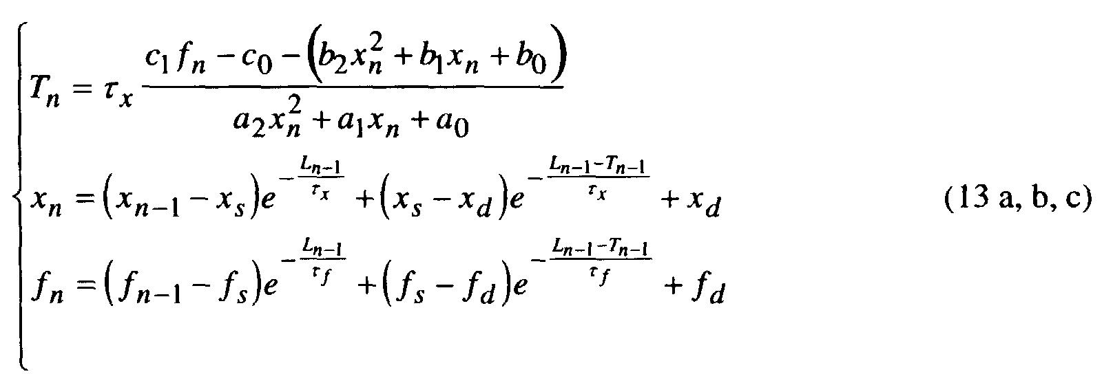
Diese mathematische Modelldarstellung stellt ein wichtiges Teilergebnis für die angestrebte Systemidentifikation dar, deren Gleichungen den nichtlinearen dynamischen Zusammenhang zwischen den Zustandsgrößen: Aktionspotentialdauer (T) und den Torvariablen x und f zum Ausdruck bringen. Eingangssignal des Systems ist dabei die Zykluslänge L. Als wichtigste Größen bezüglich der Fruherkennung von Arrhythmien sind die Modellparameter τ x , c1 und c0 hervorzuheben. τ x stellt dabei die Zeitkonstante des dynamischen K-Kanals dar, während c1 und c0 gemäß ihrer Definition in (10 b, c) die Verhältnisse der Ca- und K-Stromamplituden ausdrücken. Letztendlich sind letztere ein Maß für die Leitfähigkeiten der betreffenden Ionenkanäle und liefern Aussagen über deren Arbeitspunkte.This mathematical model representation represents an important partial result for the desired system identification, the equations of which express the nonlinear dynamic relationship between the state variables: action potential duration (T) and the gate variables x and f. The input signal of the system is the cycle length L. The most important variables with regard to the early detection of arrhythmias are the model parameters τ x , c 1 and c 0 . τ x represents the time constant of the dynamic K channel, while c 1 and c 0, as defined in (10 b, c), express the ratios of the Ca and K current amplitudes. Ultimately, the latter are a measure of the conductivity of the relevant ion channels and provide information about their operating points.
Im Gegensatz zu dem in [[6]] oder anderen Arbeiten der Literatur eingesetzten Zellmodellen steht die in (13) zusammengefaßte Systembeschreibung für ein diskretes Ersatzmodell der Zelle im Hinblick auf die Abhängigkeit der Aktionspotentialdauer von der Stimulationsfrequenz. Die sonst kontinuierlichen Zustandsgrößen x und f werden hier durch die Zahlenfolgen xn und fn repräsentiert, die jeweils die Anfangswerte der betreffenden kontinuierlichen Größen zu Beginn eines jeden Aktionspotenials darstellen.In contrast to the cell models used in [[6]] or other literature work, the system description summarized in (13) stands for a discrete replacement model of the cell with regard to the dependence of the action potential duration on the stimulation frequency. The otherwise continuous state variables x and f are represented here by the sequences of numbers x n and f n , which each represent the initial values of the relevant continuous variables at the beginning of each action potential.
Unter Kenntnis der physiologischen Modellparameter und des Zustandsvektors entsprechend eines Aktionspotentials ist es nun möglich die Dauer des nächstfolgenden Aktionspotentials zu berechnen. Diese rekursive Rechenvorschrift bringt auch den Nachweis des in der Literatur oft diskutierten 'memory'-Effekts der Herzmuskelzelle. Wie weit jedoch das Gedächtnis meßbar in die Vergangenheit reicht, hängt von den konkreten Systemparametern ab.Knowing the physiological model parameters and the state vector according to an action potential, it is now possible to extend the duration of the to calculate the next action potential. This recursive calculation rule also provides evidence of the 'memory' effect often discussed in the literature Cardiac muscle cell. How far memory can be measured in the past enough depends on the specific system parameters.
Obwohl nun eine vollständige Systembeschreibung vorliegt, ist die Rückrechung der Zellparameter, die Aufschlüsse über den arrhythmogenen Zustand des Substrats liefern sollen, in dieser Form noch nicht möglich. Bezüglich der hier vorliegenden Fragestellung sind unter klinisch vertretbarem Aufwand nur die Zykluslänge L und die Repolarisationszeit T (in Form der APD, der QT-Zeit oder ähnlicher Größen) meßbar. Die Modellgleichungen (13) beinhaltet jedoch noch innere Größen (Torvariablen x und f), die meßtechnisch nicht zugänglich sind. Das Ziel der nächsten Maßnahmen besteht nun darin, diese inneren Größen zu eliminieren.Although a complete system description is now available, the retroactive accounting is the Cell parameters, the information about the arrhythmogenic state of the substrate should not deliver in this form yet. Regarding the present here The question is, with clinically justifiable effort, only the cycle lengths L and the repolarization time T (in the form of the APD, the QT time or similar variables) measurable. However, the model equations (13) still contain inner quantities (Gate variables x and f), which are not accessible by measurement. The goal of the next Measures now consist in eliminating these inner sizes.
Dazu wird das System in einem eingeschwungenen Zustand betrachtet, also dann,
wenn dieses bereits eine längere Zeit mit einer konstanten Frequenz stimuliert wurde,
so daß transiente Vorgänge abgeschlossen sind. Aus Fig. 3a ist zwar ersichtlich, daß
die Zelle bezüglich der Aktionspotentialdauer einen inneren Grenzzyklus aufweist;
dieser soll allerdings bei der Herleitung vernachlässigt werden. Da ohnehin an das
Verfahren der Anspruch gestellt wird, Hinweise auf eine sich anbahnende Arrhythmie
bereits dann zu liefern, wenn noch kein signifikanter Anstieg in der Herzrate
ersichtlich ist, kann auf die Torvariable f als Zustandsvariable verzichtet werden. Ist
die Zykluslänge nämlich ausreichend groß (Stimulationsfrequenz entsprechend klein)
so ist f zu Beginn eines jeden Aktionspotential bereits eingeschwungen und hat etwa
den Wert fn = 1. Ferner ist aus Untersuchungen an Zellmodellen bekannt, daß der
diastolische asymptotische Wert der x-Variable (xd) annähernd 0 ist und xn als
Anfangswert von x zu Beginn des Aktionspotentials (insbesondere bei nicht all zu
hohen Stimulationsraten) wesentlich kleiner als 1 ist. Die Vereinfachungen die sich
hieraus ergeben, werden mathematisch wie folgt formuliert:
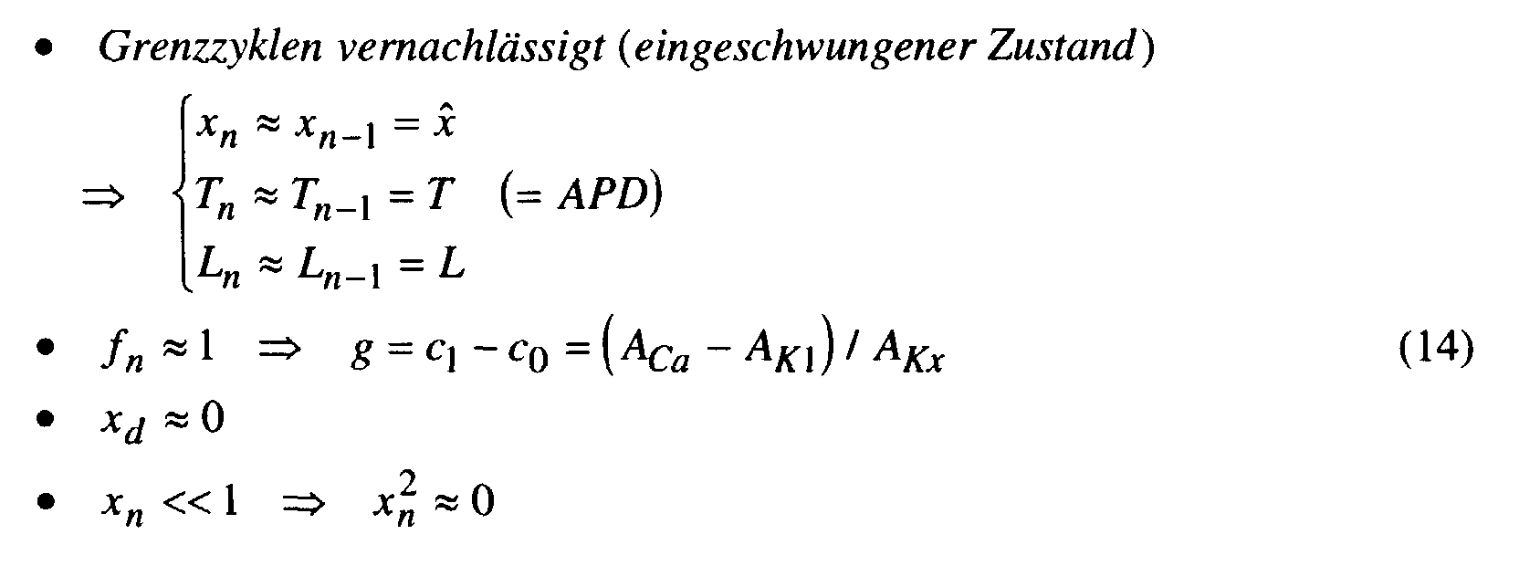
Damit resultiert aus (13 b):
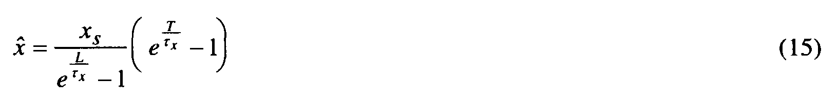
Mit dem Ziel die Abhängigkeit zwischen T und L zu bekommen, also die
meßtechnisch bestimmbare APD(HR)|∞ -Kennlinie formelmäßig zu beschreiben, ist
es sinnvoll Beziehung (15) linear zu approximieren. Damit kann T später explizit
ausdrücken werden. Linearisiert wird an der Stelle T=T1, wobei hierfür ein
physiologisch zu erwartender Wert der Aktionspotentialdauer einzusetzen ist (z.B.
T1=200 ms). Es gilt:

Eingesetzt in (13 a) ergibt:
Die quadratische Gleichung (19) ist unter Berücksichtigung, daß λ reell und λ > 0
ist, zu lösen: Bei Betrachtung der Koeffizientenwerte und deren Variationsgrenzen
unter physiologischen Bedingungen ist die gesuchte Lösung:
Die Gefahr, daß im ungünstigen Fall die Lösung komplexwertig ausfallen kann, bleibt
noch bestehen. Diese Frage ist jedoch anhand einer Parameterdiskussion nicht mit
vertretbarem Aufwand zu klären. Sie muß daher bei der Entwicklung der Algorithmen
berücksichtigt und durch numerische Maßnahmen abgehandelt werden.
Durch Rücksubstitution erhält man aus (21):
Parameter dieser Beziehung sind τ x die Zeitkonstante des dynamischen K-Kanals, und g, ein Ausdruck der aufgrund von (14) und (10 b, c) die Verhältnisse zwischen den Permeabilitäten des Ca- und der K-Kanäle beschreibt.Parameters of this relationship are τ x the time constant of the dynamic K-channel, and g , an expression that describes the relationships between the permeabilities of the Ca and the K-channels on the basis of (14) and (10 b, c).
Es ist damit gelungen auf Parameter von genau den Ionenkanälen zurück zu rechen, deren Schlüsselrolle im Prozeß der Arrhythmogenese bereits durch experimentelle elektrophysiologische Studien bestätigt wurde [[7]].It was thus possible to calculate back to parameters from exactly the ion channels, their key role in the process of arrhythmogenesis already through experimental electrophysiological studies has been confirmed [[7]].
Gefragt ist jedoch nicht die Aktionspotentialdauer selbst als Funktion der zugehörigen Zykluslänge - genau diese Größen sind meßbar und damit bekannt - sonder die physiologischen Parameter τ x und g die den Zustand des Substrats charakterisieren. Die nichtlineare und transzendente Verknüpfung dieser Größen in Beziehung (23) erschwert allerdings das Vorhaben, deren Werte zu bestimmen.However, the action potential duration itself is not required as a function of the associated cycle length - exactly these variables can be measured and are therefore known - but rather the physiological parameters τ x and g which characterize the state of the substrate. However, the nonlinear and transcendental combination of these quantities in relation (23) makes it difficult to determine their values.
Fig. 8 veranschaulicht die Abhängigkeit der Aktionspotentialdauer T von den physiologischen Parameter τ x und g in der Form einer Flächenschaar, deren Schaarparameter die Stimulationsfrequenz ist. An der Tangentialebene im Punkt P 0 =(τ x 0,g 0) ist zu erkennen, daß diese Flächen zwar geringfügig gekrümmt sind, aber auch eine linearisierte Beschreibung diesen Zusammenhang in guter Näherung approximiert. Diese Tatsache rechtfertigt es, im folgenden Beziehung (23) hinsichtlich der Parameter τ x und g zu linearisieren. Dann nämlich können deren Werte basierend auf einem linearen Gleichungssystem berechnet werden.FIG. 8 illustrates the dependency of the action potential duration T on the physiological parameters τ x and g in the form of a pair of surfaces, whose pair parameter is the stimulation frequency. On the tangential plane at point P 0 = (τ x 0 , g 0 ) it can be seen that, although these surfaces are slightly curved, a linearized description approximates this relationship to a good approximation. This fact justifies linearization in the following relationship (23) with regard to the parameters τ x and g . Then their values can be calculated based on a linear system of equations.
Dazu ist es notwendig, die partiellen Ableitungen der Funktion T(L,τ x ,g) bezüglich
der Parameter τ x und g zu ermitteln:

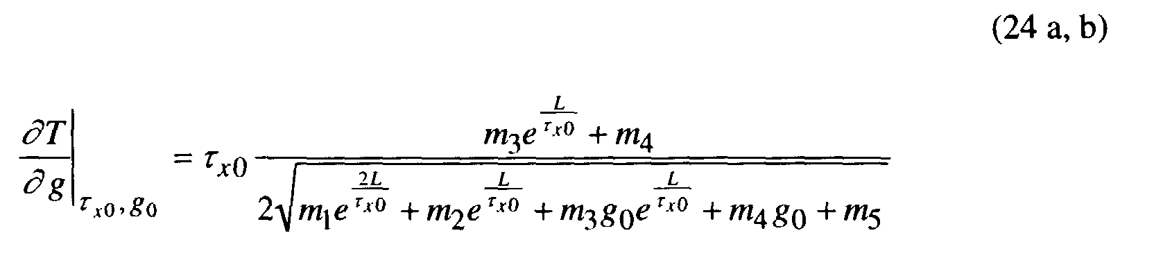
In linearisierter Form lautet damit der Zusammenhang zwischen der
Aktionspotentialdauer und der Zykluslänge:
Diese Beziehung stellt im folgenden die Grundlage für die Entwicklung eines Algorithmus zur Bestimmung der Parameter τ x und g dar, also der Größen, die Informationen über den Funktionszustand der Ca- und K-Kanäle hinsichtlich einer drohenden Arrhythmie liefern.In the following, this relationship forms the basis for the development of an algorithm for determining the parameters τ x and g , that is to say the quantities which provide information about the functional state of the Ca and K channels with regard to an impending arrhythmia.
Wie bereits erwähnt, sind die zu messenden Größen die Zykluslänge L und die
Repolarisationszeit T (ganz allgemein gesehen). Diese sind über einen Zeitabschnitt
von mehreren Herzschlägen (mindestens 2) aus dem intrakardialen Meßsignal zu
extrahieren. Daraus werden M Wertepaare:
- Abtastfrequenz:
Eine Abtastfrequenz von 1000 Hz ist insbesondere im Hinblick auf die Algorithmen zur Signalvermessung anzustreben. Geht man aber davon aus, daß der Meßfehler hinsichtlich der Verteilung durch weißes Rauschen genähert werden kann, so ist auch eine Abtastfrequenz von mindestens jedoch 500 Hz noch akzeptabel. Ohnehin wird wie anschließend beschrieben das Gleichungssystem zur Bestimmung der Parameter nach der Methode der kleinsten Fehlerquadrate gelöst. D.h. es werden eine größere Anzahl von Meßwertpaaren verrechnet, wobei sich Fehler (weißes Rauschen) ausmitteln. Strebt man eine Optimierung der Verfahren hinsichtlich der Rechenzeit an, ist eine möglichst genaue zeitliche Auflösung des Signals von Vorteil, da sich damit der Aufwand für die Signalvorverarbeitung verringert. - Amplitudenauflösung:
An sich ist zwar nur die zeitliche Information von Interesse. Da jedoch die Repolarisationszeit (aus dem noch nicht näher spezifizierten Signal) durch entsprechende Signalverarbeitung ermittelt werden muß, kann diese Frage nur dann genauer beantwortet werden, wenn sowohl das verwendete Meßsignal als auch die Auswertealgorithmen feststehen. Dazu sind jedoch erst eine Reihe klinischer Messungen als Grundlage zur Entwicklung dieser Algorithmen notwendig. Es muß anhand der Signale, die überhaupt durch das Implantat praktisch erfaßt werden können (z.B. IEGM, Coronaris-Sinus-Signal) geklärt werden, welcher Signaltyp sich am besten eignet. Da allerdings auch die Amplitudenauflösung die Genauigkeit bei der Bestimmung des Repolarisationzeitpunktes beeinträchtigt, kann jetzt schon gesagt werden, daß eine Auflösung von unter 8 bit nicht brauchbar ist.
- Sampling frequency:
A sampling frequency of 1000 Hz is particularly desirable with regard to the algorithms for signal measurement. However, if one assumes that the measurement error can be approximated with regard to the distribution by means of white noise, then a sampling frequency of at least 500 Hz is still acceptable. In any case, as described below, the system of equations for determining the parameters is solved using the least squares method. This means that a larger number of measured value pairs are calculated, errors (white noise) being averaged out. If the aim is to optimize the methods with regard to the computing time, the temporal resolution of the signal that is as accurate as possible is advantageous since this reduces the outlay for signal preprocessing. - Amplitude resolution:
In itself, only the temporal information is of interest. However, since the repolarization time (from the signal, which has not yet been specified in more detail) must be determined by appropriate signal processing, this question can only be answered more precisely if both the measurement signal used and the evaluation algorithms are fixed. However, this requires a series of clinical measurements as the basis for developing these algorithms. It must be clarified on the basis of the signals that can actually be detected by the implant (eg IEGM, Coronaris sinus signal) which signal type is best suited. However, since the amplitude resolution also affects the accuracy when determining the repolarization time, it can already be said that a resolution of less than 8 bits cannot be used.
Berücksichtigt man Forderung (14) so sind die Zeitintervalle, während denen die Meßwertpaare (L m ,T m ) erfaßt werden, so zu wählen, daß so gut es möglich ist, ein eingeschwungener Zustand vorliegt. Dieses ist zwar anhand der Variabilität der Herzrate leicht festzustellen, doch wie die später vorgestellten Simulationsergebnisse zeigen, ist es schon hinreichend, wenn sich die Meßgrößen nicht all zu plötzlich ändern (Änderungsgeschwindigkeit der Herzrate < 10 bpm/Herzschlag), um dennoch gute Ergebnisse zu erhalten.If requirement (14) is taken into account, the time intervals during which the measured value pairs ( L m , T m ) are recorded should be selected so that a steady state is present as well as possible. Although this can easily be determined from the variability of the heart rate, as the simulation results presented later show, it is sufficient if the measured variables do not change all too suddenly (rate of change of the heart rate <10 bpm / heartbeat) in order to nevertheless obtain good results .
Ausgehend von den Meßwertpaaren (L m ,T m ) wird unter Verwendung von (26) das
folgende lineare Gleichungssystem aufgebaut:
Eine weitere Verbesserung erzielt man durch eine iterative Gestaltung des Algorithmus zur Parameterextraktion. Für die Aufstellung und Lösung des Gleichungssystems (28) ist es ohnehin erforderlich, eine Schätzlösung (τ x 0,g 0) für die Parameter, d.h. den Berührungspunkt P0 der Tangentialebene, vorzugeben. Diese Werte können aus physiologischen Überlegungen bzw. aus der Erfahrung hergeleitet werden. Da die Tangentialebene die Fläche in Fig. 8 auch über weitere Bereiche hinweg noch gut nähert, können in nullter Näherung für (τ x 0,g 0) die dem gesunden Zustand entsprechenden Werte eingesetzt werden, ohne daß die Genauigkeit der Lösung extrem beeinträchtigt wird.A further improvement is achieved through an iterative design of the algorithm for parameter extraction. In order to set up and solve the system of equations (28), it is necessary anyway to specify an estimation solution (τ x 0 , g 0 ) for the parameters, ie the point of contact P 0 of the tangential plane. These values can be derived from physiological considerations or from experience. Since the tangential plane also approximates the surface in FIG. 8 well over other areas, the values corresponding to the healthy state can be used in a zero approximation for (τ x 0 , g 0 ) without the accuracy of the solution being extremely impaired.
Dennoch ist es vorteilhaft die Genauigkeit der Lösung iterativ zu verbessern. Ausgehend von der Startlösung (τ x 0,g 0) werden die Koeffizienten des Gleichungssystems (28) bestimmt, und daraus die Lösung (τ x 0, g) ermittelt. Diese dient nun als Startlösung für die nächste Iteration. Als Abbruchkriterien dienen zwei Fakten: entweder unterscheiden sich die Lösungen (im Sinne der L2-Norm) um weniger als ein geforderter Schwellwert, oder die Anzahl der Iterationen überschreitet einen vorgegebenen akzeptierbaren Wert. Durch das zweite Kriterium ist insbesondere sichergestellt, daß bei divergentem Verhalten, der Algorithmus nicht in eine Endlosschleife führt. Bricht die Iteration aufgrund des zweiten Kriteriums ab, liegt keine Lösung vor. Wie bereits bei der Diskussion von Beziehung (21) erwähnt, die hier in der Form (28 d) in Erscheinung tritt, ist jetzt noch darauf zu achten, daß die Lösung nicht komplexe Werte annimmt. Ist dieses nämlich infolge eines ungünstigen Meßdatensatzes der Fall, wurde keine physiologisch sinnvolle Lösung für τ x und g gefunden, so daß ein neuer Meßdatensatz gewählt werden muß.Nevertheless, it is advantageous to iteratively improve the accuracy of the solution. Starting from the starting solution (τ x 0 , g 0 ), the coefficients of the system of equations (28) are determined and the solution (τ x 0 , g ) is determined from them. This now serves as a starting solution for the next iteration. Two facts serve as termination criteria: either the solutions (in the sense of the L 2 standard) differ by less than a required threshold value, or the number of iterations exceeds a predetermined acceptable value. The second criterion ensures, in particular, that in the case of divergent behavior, the algorithm does not lead to an endless loop. If the iteration stops due to the second criterion, there is no solution. As already mentioned in the discussion of relationship (21), which appears here in the form (28 d), care must now be taken that the solution does not assume complex values. If this is the case because of an unfavorable measurement data record, no physiologically sensible solution for τ x and g was found, so that a new measurement data record must be selected.
Abschließend visualisieren Fig. 9a, 9b und 9c ein Anwendungsbeispiel dieses Parameter-schätzalgorithmus. Die Fig. 9a und 9b zeigen zum einen die Herzrate (HR) (hier stellvertretend für L), für die in der Simulation ein zufälliger jedoch physiologisch vertretbarer Verlauf angenommen wurde. Zum anderen wurde die Repolarisationszeit T (hier in Form der APD) basierend auf der Modellbeschreibung (13) simuliert. Die Anfangswerte der Zustandsgrößen entsprechen einem eingeschwungenen Zustand bei einer Stimulationsfrequenz von 70 bpm (x0=0.0348, f0=0.9999, T0=239,5 ms).Finally, FIGS. 9a, 9b and 9c visualize an application example of this parameter estimation algorithm. 9a and 9b firstly show the heart rate (HR) (here representative of L), for which a random but physiologically acceptable course was assumed in the simulation. On the other hand, the repolarization time T (here in the form of the APD) was simulated based on the model description (13). The initial values of the state variables correspond to a steady state with a stimulation frequency of 70 bpm (x 0 = 0.0348, f 0 = 0.9999, T 0 = 239.5 ms).
Diese beiden Trendgrößen (HR und T), die in der klinischen Praxis zunächst aus einem geeigneten intrakardialen Meßsignal als Zahlenfolgen extrahiert werden müssen, stellen die Eingangsgrößen des Schätzalgorithmus dar. In der Fig. 9c ist die APD(HR)|∞ -Kennlinie aufgetragen, die aus Beziehung (23) resultiert. Parameter dieser Kurve sind die zurückgerechneten Zellparameter (τ x ,g). Daher vermittelt die Morphologie dieser Kennlinie Aussagen über den zellulären Funktionszustand.These two trend variables (HR and T), which in clinical practice must first be extracted from a suitable intracardiac measurement signal as sequences of numbers, represent the input variables of the estimation algorithm. In FIG. 9c the APD ( HR ) | ∞ curve plotted, which results from relationship (23). The parameters of this curve are the recalculated cell parameters (τ x , g ). The morphology of this characteristic curve therefore provides information about the cellular functional state.
Um noch einen Einblick quantitativer Natur zu vermitteln, sei das folgende Zahlenbeispiel genannt. Im konkreten Fall (Fig. 9a, 9b und 9c) wurden zur Vorwärtssimulation nach (13) die Parameter τ x = 158 ms und g =0.65 vorgegeben, während als Startwerte für die iterative Rückrechung τ x 0 =200 ms und g 0 =0.5 galten. Als Ergebnis der Parameterschätzung wurden die Werte τ x = 160.6788 ms und g =0.6366 innerhalb von 3 Iterationen erhalten.To give you an insight of a quantitative nature, the following numerical example is mentioned. In the specific case (FIGS. 9a, 9b and 9c) the parameters τ x = 158 ms and g = 0.65 were specified for the forward simulation according to (13), while τ x 0 = 200 ms and g 0 = 0.5 were used as starting values for the iterative recalculation were considered. As a result of the parameter estimation, the values τ x = 160.6788 ms and g = 0.6366 were obtained within 3 iterations.
Um modelltechnisch die Leistungsfähigkeit des beschriebenen Algorithmus nachzuweisen, werden im folgenden als Grundlage einer quantitativen Beurteilung adäquate Testumge-bungen konstruiert. Dabei wird die Parameterrückrechung sowohl im Bezug auf das Ersatzmodell wie auch auf das physiologisch vollständige Zellmodell untersucht.To model the performance of the algorithm described The following are the basis for a quantitative assessment adequate test environments constructed. The parameter recalculation is both in terms of the replacement model as well as the physiologically complete one Cell model examined.
Ausgehend vom Ersatzmodell (13) wurden mehrfach Approximationen vorgenommen, so daß zunächst die Genauigkeit des Verfahrens geprüft werden muß. Vorgenommen wird dieses am Ersatzmodell, da allein daran diese Frage unter definierten Randbedingungen (das Ersatzmodell war Ausgangspunkt für den Entwurf des Parameterschätzverfahrens) beurteilt werden kann. Starting from the replacement model (13), several approximations were made made so that the accuracy of the method must be checked first. This is done on the replacement model, because this question alone defined boundary conditions (the replacement model was the starting point for the design of the parameter estimation method) can be assessed.
Für die Tests werden sowohl stochastische als auch deterministische Herzratenverläufe vorgegeben. Die Ermittlung der zugehörigen APD-Werte erfolgt aufgrund der Rekursionsformeln aus (13) und den gleichen Anfangswerten wie im obigen Abschnitt. Die Herzrate startet daher jeweils von 70 bpm, wobei sich deren Variation bei diesen Tests auf 70±10bpm beschränkt. Hintergrund dieser Maßnahme ist zu prüfen, in wie fern das Verfahren auch bei geringer Auslenkung des Systems funktioniert, d.h. also zu klären ob natürliche Variationen der Herzrate (auch ohne explizite Belastung des Patienten) schon ausreichend sind.For the tests, both stochastic and deterministic Heart rate profiles given. The associated APD values are determined based on the recursion formulas from (13) and the same initial values as in section above. The heart rate therefore starts from 70 bpm, whereby their Variation in these tests is limited to 70 ± 10bpm. Background of this measure the extent to which the procedure is to be checked, even if the system is only slightly deflected works, i.e. So to clarify whether natural variations in the heart rate (even without explicit burden on the patient) are sufficient.
Die Simulationen wurden systematisch für zahlreiche vorgegebene Paramterkombinationen (τ x , g) durchgeführt, deren Variationsbereich (basierend auf Werten der Literatur [[15]]) und Raster aus Fig. 10 zu entnehmen sind.The simulations were carried out systematically for numerous predefined combinations of parameters (τ x , g ), the range of which (based on values from the literature [[15]]) and grid from FIG. 10 can be seen.
Zunächst wurde das Verhalten bei einem deterministisch vorgegebenen Herzratenverlauf in Form einer Rampe zwischen 60 bpm und 80 bpm getestet. In der Praxis bedeutet dies, daß der Schrittmacher ein solches Stimulationsprotokoll befolgen muß, um das System auszulenken. Unter diesen Rahmenbedingungen zeichnet sich die Parameterrückrechnung durch relative Fehler unterhalb 2% aus, während überwiegend nur 3 Iterationen benötigt werden.First, the behavior was given a deterministic Heart rate curve tested in the form of a ramp between 60 bpm and 80 bpm. In the In practice, this means that the pacemaker has such a stimulation protocol must follow to deflect the system. Under these conditions the parameter recalculation is characterized by relative errors below 2%, while mostly only 3 iterations are needed.
Im Falle des stochastisch stimulierten Systems muß mit relativen Fehlern von bis zu 5% gerechnet werden, wobei es gelegentlich auch vorkommen kann, daß aufgrund eines gerade ungünstigen Meßwertsatzes, kein physiologisch sinnvolles Ergebnis (z.B. komplexer Wert) erzielt wird. Die Zahl der benötigten Iterationen ist in Abhängigkeit der konkreten Paramterwerte in Fig. 10 dargestellt. Grundsätzlich ist zu bemerken, daß die Bestimmung des Parameters g (auch bei deterministischen Herratenverläufen) weniger fehlerbehaftet ist als die Zeitkonstante τ x .In the case of the stochastically stimulated system, relative errors of up to 5% must be expected, although it can occasionally occur that a physiologically sensible result (eg complex value) is not achieved due to an unfavorable set of measured values. The number of iterations required is shown in FIG. 10 as a function of the specific parameter values. In principle, it should be noted that the determination of the parameter g (even in the case of deterministic curves) is less prone to errors than the time constant τ x .
Die Simulationsergebnisse zeigten, daß auch bei stochastischen Herzratenverläufen, die den natürlichen nahekommen, noch brauchbare Ergebnisse erzielt werden. Es ist daher nicht unbedingt notwendig, zur Systemidentifikation ein bestimmtes vorgegebenes Stimulationsprotokoll starr zu befolgen, das ggf. sogar den momentanen Bedürfnissen des Organismus nicht entspricht. Das Implantat erfüllt in diesem Sinne überwiegend die Rolle eines diagnostischen Beobachters und veranlaßt nur bei Bedarf eine therapeutische Maßnahme.The simulation results showed that even with stochastic heart rate profiles, that come close to natural, still usable results. It is therefore not absolutely necessary to identify a specific system rigidly follow the specified stimulation protocol, which may even be the does not meet current needs of the organism. The implant fulfills in In this sense, the role of a diagnostic observer and prompted a therapeutic measure only if necessary.
Im nächsten Schritt wird das Verfahren unter realitätsnahen Arbeitsbedingungen untersucht. Als Testobjekt (zu identifizierendes System) dient ein Zellmodell (basierend auf [[6]]), dessen Zustandsgrößen unmittelbar physiologische Größen abbilden. Damit ist es möglich, pathologisches Systemverhalten im direkten Bezug zu klinischen Studien simulationstechnisch nachzubilden. The next step is the process under realistic working conditions examined. A cell model serves as the test object (system to be identified) (based on [[6]]), the state variables of which are directly physiological variables depict. This makes it possible to directly identify pathological system behavior simulation of clinical studies.
Zunächst wird der grundsätzliche Zusammenhang zwischen den Größen APD und HR untersucht, die Ausgangspunkt der Systemidentifikation sind. Die Figuren 10 und 11 veranschaulichen diesen Zusammenhang für das nun physiologische Zellmodell anhand von zwei Stimulationsprotokollen. In Fig. 11a und 11b wird ähnlich wie in Fig. 3a und 3b die Reaktion des Systems auf eine sprunghafte Veränderung der Stimulationsfrequenz dargestellt. In Fig. 11a wurden die Meßwertpaare (HR, APD) (entsprechend (27)) als Punkte aufgetragen (Gruppen bestehend aus mehreren Meßwertpaaren für jeweils die Stimulationsfrequenz nach dem Sprung). Die durchgezogene Linie stellt hingegen die hieraus (über (τ x , g)) berechnete APD( HR)|∞ -Kennlinie dar, die das Ergebnis der Systemidentifikation visualisiert. Fig. 11b verbildlicht den Einschwingvorgang selbst: einerseits für das physiologische Zellmodell und andererseite für das Ersatzmodell. Die für das Ersatzmodell notwendigen Parameterwerte (τ x , g) wurden dabei aus den Messungen am physiologischen Modell rückgerechneten. Fig. 11b verdeutlicht insbesondere, wie detailgetreu das Ersatz-modell selbst den Einschwingvorgang nachbildet, also trotz Vereinfachungen auch quantitativ ein physiologisch korrektes Verhalten aufweist.First, the basic relationship between the quantities APD and HR is examined, which are the starting point for system identification. FIGS. 10 and 11 illustrate this relationship for the now physiological cell model using two stimulation protocols. 11a and 11b, similar to FIGS. 3a and 3b, show the system's response to a sudden change in the stimulation frequency. In Fig. 11a the measured value pairs (HR, APD) (corresponding to (27)) were plotted as points (groups consisting of several measured value pairs for the stimulation frequency after the jump). The solid line, on the other hand, represents the APD ( HR ) | calculated from this (via (τ x , g )) ∞ curve that visualizes the result of the system identification. 11b illustrates the transient process itself: on the one hand for the physiological cell model and on the other hand for the replacement model. The parameter values (τ x , g ) required for the replacement model were calculated back from the measurements on the physiological model. 11b illustrates in particular how detailed the replacement model itself simulates the transient process, that is, despite simplifications, also has a physiologically correct behavior in quantitative terms.
Als wichtige Aussage von Fig. 11b ist auch festzuhalten, das die Schwingungen der Aktionspotentialdauer kurz nach dem Sprung vorwiegend auf den dynamischen Einschwingvorgang zurückzuführen sind (den selbst das Ersatzmodell wiedergibt), während die Oszillationen im weiteren Verlauf durch den inneren Grenzzyklus verursacht sind. Anders ausgedrückt, klärt damit diese Studie auch, wie ausgeprägt das bereits angesprochene Gedächtnis der Zelle ist, beziehungsweise skizziert sie ein Verfahren, dieses zu messen. Obgleich aus theoretischer Sicht rekursive Systeme ein unendlich langes Gedächtnis haben, ist im konkreten Fall das praktisch meßbare Gedächtnis der Zelle (zumindest im Hinblick auf die hier betrachteten Phänomene) auf etwa 6-7 Zyklen begrenzt. Diese Zahl stellt die Anzahl der signifikanten Überschwinger der APD nach dem Frequenzsprung dar (Fig. 11b).As an important statement from FIG. 11b, it should also be noted that the vibrations of the Action potential duration shortly after the jump mainly on the dynamic Settling process (which is itself reproduced by the replacement model), while the oscillations continue through the inner limit cycle are caused. In other words, this study also clarifies how pronounced is the memory of the cell that has already been addressed, or is a sketch of it Procedure to measure this. Although from a theoretical point of view recursive systems Having an infinitely long memory is what is practically measurable in a specific case Memory of the cell (at least with regard to the phenomena considered here) limited to about 6-7 cycles. This number represents the number of significant APD overshoot after the frequency hopping (Fig. 11b).
Am Beispiel eines weiteren Tests zeigen Fig. 12a und 12b, daß auch unter anderen Rahmenbedingungen sich das Ersatzmodell physiologisch richtig verhält. Das hier verwendete Protokoll setzt zur Anregung des Systems einen rampenförmig ansteigenden Verlauf der Stimulationsfrequenz ein. Bezüglich der dargestellten Größen sind Fig. 11a, 11b und Fig. 12a, 12b analog.Taking another test as an example, FIGS. 12a and 12b show that among others Framework conditions, the replacement model behaves correctly physiologically. This one The protocol used sets a ramp to excite the system increasing course of the stimulation frequency. Regarding the illustrated Sizes are analogous to FIGS. 11a, 11b and 12a, 12b.
Erwartungsgemäß soll das entwickelte Verfahren auch in der Lage sein, Veränderungen der Substrateigenschaften zu erkennen. Getestet wurde diese Fähigkeit unter Verwendung des physiologischen Zellmodells, wobei konkret die Permeabilität des Ca-Kanals modifiziert und/oder die Relaxationskennlinie τ x (Vm) des dynamischen K-Kanals entlang der Abszisse verschoben wurde. Die Tabelle faßt die Größen zusammen, die einerseits die Veränderungen an den Ionenkanälen beschreiben und andererseits die aus den simulierten Messungen bestimmten Systemparameter (τ x , g) wiedergeben. Graphisch sind diese Ergebnisse in Fig. 13a und 13b veranschaulicht.As expected, the developed method should also be able to detect changes in the substrate properties. This ability was tested using the physiological cell model, specifically modifying the permeability of the Ca channel and / or shifting the relaxation characteristic τ x ( Vm ) of the dynamic K channel along the abscissa. The table summarizes the quantities which, on the one hand, describe the changes in the ion channels and, on the other hand, reflect the system parameters (τ x , g ) determined from the simulated measurements. These results are graphically illustrated in Figures 13a and 13b.
Die nachfolgende Tabelle zeigt rückgerechnete Parameterwerte für modifiziertes
Zellverhalten, wobei Ca_mod die Permeabilität des Ca-Kanals multiplikativ verändert
und τ x die Verschiebung der Relaxationskennlinie des dynamischen Kanals darstellt.
Aus der Tabelle ist ersichtlich, daß bei einer Vergrößerung der Permeabilität des Ca-Kanals (Ca_mod>1) aufgrund der Beziehungen (10 b, c) und (14) erwartungsgemäß auch der Wert von g ansteigt. Betrachtet man die Relaxationskennlinie τ x (V m ) [[6]], ist ebenfalls festzustellen, daß in Übereinstimmung mit der Tabelle die Werte von τ x bei einer Linksverschiebung ansteigen bzw. bei einer Rechtsverschiebung kleiner werden.It can be seen from the table that, as the permeability of the Ca channel (Ca_mod> 1) increases, the value of g increases as expected due to the relationships (10 b, c) and (14). Looking at the relaxation characteristic τ x ( V m ) [[6]], it can also be seen that, in accordance with the table, the values of τ x increase with a left shift or decrease with a right shift.
Man bemerkt jedoch auch, daß sich die am physiologischen Zellmodell verursachten Modifikationen nicht allein nur auf den einen oder anderen zurückgerechneten Systemparameter auswirken, sondern, daß diese gewisserweise voneinander abhängen. Diese Tatsache ist zwar einerseits den in die Modellbetrachtung eingebrachten Vereinfachungen zuzuschreiben, andererseits aber hängt genau betrachtet g (wegen Beziehung (10 b, c)) von den Verhältnissen der Ca- und K-Stromamplituden ab und nicht von den Leitfähigkeiten selbst. Eine Verschiebung der Relaxationskennline des dynamischen K-Kanals wirkt sich in erster Linie auf den K-Strom selbst aus, aber auch indirekt (über die dadurch veränderte Transmembranspannung) auf den Ca-Strom. Damit wird verständlich, warum sich die Verschiebung der Relaxationskennline auch auf g auswirkt.However, it is also noted that the modifications caused on the physiological cell model do not only affect one or the other recalculated system parameters, but that they depend to some extent on one another. On the one hand, this fact can be attributed to the simplifications introduced in the model, but on the other hand, g (on the basis of relationship (10 b, c)) depends on the ratios of the Ca and K current amplitudes and not on the conductivities themselves The relaxation characteristic of the dynamic K-channel primarily affects the K-current itself, but also indirectly (via the transmembrane voltage that changes as a result) on the Ca-current. This explains why the shift in the relaxation curve also affects g .
Ähnlich läßt sich der andere Zusammenhang begründen. Wird die Permeabilität des Ca-Kanals (über Ca_mod) modifiziert, zieht dieses Veränderungen in der Aktionspotentialform mit sich, die ihrerseits das Relaxationsverhalten des dynamischen K-Kanals beeinflußt. Diese Tatsache führt bei der Parameterrückrechnung zu einem entsprechend anderen Wert von τ x .The other context can be justified in a similar way. If the permeability of the Ca channel is modified (via Ca_mod), this entails changes in the action potential form, which in turn influences the relaxation behavior of the dynamic K channel. This fact leads to a correspondingly different value of τ x when calculating parameters.
Die Verkopplung der identifizierten Systemparameter (τ x , g) geht aus Fig. 14a und 14b besonders gut hervor, da die Höhenlinien zu keiner der beiden Parameterachsen parallel verlaufen. Diese Graphiken repräsentieren den im Varaitionsbereich der zellulären Modellparameter Ca_mod und taux_sh bestehenden Bezug zu den Systemparametern τ x und g. Die Intervallgrenzen, innerhalb von denen die Parameter des physiologischen Zellmodells variiert wurden, können aus Fig. 14a und 14b abgelesen werden. Das Raster betrug je 11 Unterteilungen pro Parameterbereich. Zur Paramterschätzung wurden dabei (für jeden Rasterpunkt) je 100 Stimulationszyklen betrachtet.The coupling of the identified system parameters (τ x , g ) emerges particularly well from FIGS. 14a and 14b, since the contour lines do not run parallel to either of the two parameter axes. These graphics represent the relationship between the system parameters τ x and g in the variation area of the cellular model parameters Ca_mod and taux_sh. The interval limits within which the parameters of the physiological cell model were varied can be read from FIGS. 14a and 14b. The grid was 11 subdivisions per parameter area. For the parameter estimation, 100 stimulation cycles were considered (for each grid point).
Für Paramterwerte (Ca_mod, taux_sh) innerhalb der in Fig. 14a und Fig. 14b schraffierten Flächen verhält sich das Zellmodell pathologisch; es treten EADs auf. Da in diesem Extremfall die Modellbetrachtungen zur Herleitung der mathematischen Beziehung zwischen APD und HR nicht mehr gültig sind, ist auch die Anwendung des daraus entwickelten Verfahrens zur Parameterschätzung in diesem Bereich unzulässig. Daher können im schraffierten Bereich keine Werte für τ x und g angegeben werden. In Fig. 14a ist jedoch auffällig, daß der steilste Gradient von g genau in Richtung dieser Gefahrenzone zeigt.The cell model behaves pathologically for parameter values (Ca_mod, taux_sh) within the areas hatched in FIGS. 14a and 14b; EADs occur. Since in this extreme case the model considerations for deriving the mathematical relationship between APD and HR are no longer valid, the use of the method developed from this for parameter estimation in this area is also inadmissible. Therefore, no values for τ x and g can be specified in the hatched area. In Fig. 14a, however, it is striking that the steepest gradient of g points exactly in the direction of this danger zone.
Konsequent umgesetzt führt die aus dem vorigen Abschnitt hervorgehende Schlußfolgerung zur Entwicklung eines Diagnosewerkzeugs, das sowohl für die Früherkennung als auch für die Beobachtung des Fortschreitens zellulärer Erkrankungen bedeutend ist. Von den vielseitig denkbaren Anwendungsgebieten des vorgestellten Identifikationsverfahrens soll hier nur auf die klinische Einsatzmöglichkeit als EAD-Prädiktor exemplarisch eingegangen werden.Consistently implemented leads from the previous section Conclusion to develop a diagnostic tool that is suitable for both Early detection as well as for monitoring cellular progression Diseases is significant. Of the many conceivable application areas of the The identification method presented here is only intended to apply to the clinical Possible application as an EAD predictor.
Die Mechanismen und zellulären Ursachen der Arrhythmogenese sind vielschichtig und veränderte Substrateigenschaften können eine Tachykardie auf unterschiedlichste Weise auslösen. Insbesondere wurde klinisch der Zusammenhang zwischen dem Auftreten von EADs und der Reenty-basierten Arrhythmieform 'Torsade de Pointes' nachgewiesen [[10]][[11]]. Andererseits sind diese Mechanismen auch in einer Modellstudie geklärt und nachgebildet worden [[13]]. Damit schließt sich die Argumentationskette, warum dieses Verfahren explizit auch zur Früherkennung von Tachykardien anwendbar ist.The mechanisms and cellular causes of arrhythmogenesis are complex and changed substrate properties can cause tachycardia in a wide variety of ways Trigger way. In particular, the relationship between the Occurrence of EADs and the Reenty-based arrhythmia form 'Torsade de Pointes' proven [[10]] [[11]]. On the other hand, these mechanisms are also in one Model study has been clarified and reproduced [[13]]. That concludes the Chain of arguments as to why this method is also used for the early detection of Tachycardia is applicable.
In diesem Sinne kann nun die Frage beantwortet werden, ob das Substrat für eine Arrhythmie prädestiniert ist oder nicht. Streng gesehen ist von Prädiktion nur insofern zu sprechen, daß aus der trendmäßigen Beobachtung der Vergangenheit in die Zukunft extrapoliert werden kann. Das Verfahren selbst liefert jedoch nur Aussagen zum momentanen Ist-Zustand.In this sense, the question can now be answered whether the substrate for a Arrhythmia is predestined or not. Strictly speaking, prediction is only insofar to speak that from the trend observation of the past into the Future can be extrapolated. However, the process itself only provides statements to the current status.
Basierend auf diesen Überlegungen, wird im folgenden das Funktionsprinzip dieses Prädiktors für EAD-bedingte Tachykardien in einer Simulation vorgestellt. Aus Fig. 15a geht der Variationsbereich der zellulären Parameter hervor, die in der Studie die Veränderungen der Substrateigenschaften verursachen. Als Funktionswert ist die entsprechende Aktions-potentialdauer dargestellt. Dem Bild überlagert sind strahlenförmig Trajektorien eingezeichnet (der Ursprung entspricht dem gesunden Normalzustand des Substrats), entlang derer sich in der Modellrechnung die Substrateigenschaften ändern. Wie diese zeitlich durchlaufen werden, zeigt Fig. 16 in den oberen beiden Diagrammen.Based on these considerations, the functional principle of this is as follows Predictor of EAD-related tachycardia presented in a simulation. From Fig. 15a shows the range of variation of the cellular parameters, which in the study the Cause changes in substrate properties. The function value is corresponding action potential duration is shown. Are superimposed on the image radial trajectories drawn in (the origin corresponds to the healthy one Normal state of the substrate) along which the model calculation Change substrate properties. 16 shows how these are run through in time the top two diagrams.
Fig. 15b zeigt das Abbild dieser Trajektorien im Parameterraum (τ x , g). Desgleichen wurden die Grenzpunkte des schraffierten EAD-Bereichs aus der linken Abbildung in diesen Paramterraum transformiert und durch diese Punkte eine Regressionsgerade gelegt. Sie stellt im Parameterraum die Grenze zur EAD-Zone dar. In einem (frei definierbaren) Sicherheitsabstand wird parallel dazu eine weitere Gerade gelegt, die die Gefahrenzone markiert. Bewegt sich der Arbeitspunkt (τ x, g) über diese Grenze hinaus, setzt der Algorithmus ein Alarmflag.15b shows the image of these trajectories in the parameter space (τ x , g ). Likewise, the boundary points of the hatched EAD area from the illustration on the left were transformed into this parameter space and a regression line was drawn through these points. It represents the boundary to the EAD zone in the parameter space. At a (freely definable) safety distance, another straight line is laid parallel to it, which marks the danger zone. If the operating point (τ x, g ) moves beyond this limit, the algorithm sets an alarm flag.
Einen detaillierteren Einblick liefern Fig. 17a und 17b. In zwei Beispielen wird illustriert, wie das Verfahren bereits etwa 100 Herzschläge vor dem Auftreten der EADs diese Gefahr erkennt und meldet. Die genaue Anzahl der Herzschläge hängt im einzelnen allerdings von der Geschwindigkeit ab, mit der sich die Substrateigenschaften ändern. Es ist jedoch mit großer Sicherheit davon auszugehen, daß eine Erkrankung nicht plötzlich von einem Herzschlag zum anderen eintritt, sondern eher allmählich fortschreitet. In der Praxis steht damit erwartungsgemäß ein ausreichender Zeitraum für therapeutische Maßnahmen zur Verfügung.17a and 17b provide a more detailed insight. In two examples illustrates how the procedure is about 100 heartbeats before the onset of the EADs recognizes and reports this danger. The exact number of heartbeats depends on However, depending on the speed at which the Change substrate properties. However, it can be assumed with great certainty that that a disease does not suddenly occur from one heartbeat to another, but rather progresses gradually. As expected, this is the case in practice sufficient time for therapeutic measures.
Wie anhand der beiden Beispiele in Fig. 17a und 17b zu erkennen ist, reagiert das Verfahren nicht nur auf eine EAD-Gefahr, sondern kann bereits im Frühstadium auch das Ausmaß der EADs differenziert beurteilen. Während im oberen Beispiel nur sporadisch EADs auftreten, kommt es im unteren Beispiel aufgrund mehrfacher EADs zu einer schwerwiegenden Verlängerung der Aktionspotentialdauer. An den Spitzen im Verlauf dieser EADs ist zu erkennen, daß eine neue Erregung in die Refraktärzeit trifft, also ein transienter Erregungsblock entsteht. Wie bereits in [[13]] gezeigt, ist in diesem Fall die Entstehung einer kreisenden Erregung viel wahrscheinlicher als im oberen Beispiel.As can be seen from the two examples in FIGS. 17a and 17b, this reacts Procedures not only at an EAD risk, but can also be done at an early stage assess the extent of the EADs differently. While in the example above only Sporadic EADs occur, there are several in the example below EADs for a serious extension of the action potential duration. To the Spikes in the course of these EADs can be seen that a new excitement in the Refractory period hits, so a transient excitation block arises. As already in [[13]] shown, the emergence of a circular excitation is a lot in this case more likely than in the example above.
Obwohl zum Zeitpunkt der Gefahrenmeldung, den Aktionspotentialen rein visuell noch nichts anzumerken ist (Fig. 17a und 17b, linke Diagramme), kann das Verfahren anhand der identifizierten Systemparameter sogar schon feststellen, wie im konkreten Fall die EADs aussehen werden. Hinweise auf EADs liefert zwar auch der Parameter g alleine, dessen Gradient in Richtung der Gefahrenzone am steilsten ist (Fig. 14a und 14b). Die zu erwartenden EAD-Formen können jedoch erst unter Zuhilfenahme des Parameters τ x genauer spezifiziert werden.Although at the time of the hazard report, the action potential is not yet visually noticeable (Fig. 17a and 17b, left-hand diagrams), the method can even use the identified system parameters to determine what the EADs will look like in a specific case. Indications of EADs are also provided by the parameter g alone, the gradient of which is steepest in the direction of the danger zone (FIGS. 14a and 14b). However, the expected EAD forms can only be specified with the help of the parameter τ x .
Wie bereits in [[14]] gezeigt, gilt als notwendiges Kriterium zur Entstehung von EADs, daß die Aktionspotentialdauer drastisch zunimmt. Diese Tatsache wird auch durch Fig. 15a und 15b bestätigt. Als hinreichendes Kriterium kann jedoch nicht einfach ein APD-Schwellwert definiert werden, da dieser entlang der in Fig. 15a eingezeichneten EAD-Grenze um etwa 100 ms variiert. Daher ist die Spezifizität des hier entwickelten Verfahrens im Hinblick auf die Arrhythmiegefahr gegenüber derjenigen eines einfachen APD-Kriteriums in jedem Fall überlegen.As already shown in [[14]], is a necessary criterion for the development of EADs that the duration of the action potential increases drastically. This fact will too confirmed by Figures 15a and 15b. However, it cannot be a sufficient criterion an APD threshold value can simply be defined, since this follows the path shown in FIG. 15a drawn EAD limit varies by about 100 ms. Therefore, the specificity of the method developed here with regard to the risk of arrhythmia in any case superior to that of a simple APD criterion.
Ausgehend von der mathematischen Beschreibung eines physiologisch begründeten Zellmodells ist es durch vereinfachende Ansätze gelungen, die Grundlage für eine theoretische Systemidentifikation hinsichtlich der Früherkennung von Herzrhythmusstörungen zu schaffen. Im Mittelpunkt der Betrachtungen steht dabei der dynamische Zusammenhang zwischen Herzrate und Repolarisationszeit, dessen Informationsgehalt bezüglich der Arrhythmogenese durch zahlreiche experimentelle Studien der Literatur untersucht und bestätigt wurde.Based on the mathematical description of a physiologically justified Using simplified approaches, the cell model has succeeded in laying the foundation for a theoretical system identification with regard to the early detection of cardiac arrhythmias to accomplish. The focus is on the dynamic Relationship between heart rate and repolarization time Information content regarding the arrhythmogenesis by numerous experimental Studies of literature have been examined and confirmed.
Als Ergebnis der Systemidentifikation resultierten Rechenvorschriften, die es ermöglichen auf das Amplitudenverhältnis der Ca- und K-Ströme zurückzurechnen sowie die Zeitkonstante des dynamischen K-Kanals zu bestimmen. Es handelt sich dabei um Parameter die einen direkten Bezug zu klinischen Befunden herstellen und sich somit die Arrhythmiegefahr aufgrund von physiologischen Kriterien beurteilen läßt. Die zur Systemanalyse erforderlichen Eingangssignale beschränken sich dabei auf die Herzrate und die Repolarisationszeit, die aus gängigen intrakardialen Meßsignalen (z.B. IEGM) ermittelt werden können.As a result of the system identification, arithmetic rules resulted that it make it possible to calculate back to the amplitude ratio of the Ca and K currents and to determine the time constant of the dynamic K channel. It is about parameters that directly relate to clinical findings and assess the risk of arrhythmia based on physiological criteria leaves. The input signals required for system analysis are limited on the heart rate and repolarization time from common intracardiac Measurement signals (e.g. IEGM) can be determined.
Zur numerischen Berechnung der definierten Systemparameter wurden im weiteren Implementierungsvorschriften für einen Algorithmus ausgearbeitet, die die Zuverlässigkeit und Genauigkeit bei dennoch vertretbarem Rechenaufwand optimieren.For the numerical calculation of the defined system parameters, Implementation rules for an algorithm that the Reliability and accuracy with reasonable computing effort optimize.
Als praxisrelevanter Vorteil des entwickelten Verfahrens ist hervorzuheben, daß die zur Systembeobachtung erforderliche Auslenkung des Systems nicht von außen auferlegt werden muß, und damit kein unphysiologischer Eingriff in die Erregungsbildung zu befürchten ist. Die Simulationsergebnisse zeigten, daß sich auch bei natürlichen Herzraten (mit Variationen im Bereich 60-80 bpm) noch aussagekräftige Ergebnisse erzielen lassen. Das Implantat kann damit energiesparend in der Rolle eines diagnostischen Beobachters die Funktionalität des Syncytium überwachen und nur bei Bedarf therapeutische Maßnahmen einleiten. Hinsichtlich der Spezifizität kann geschlußfolgert werden, daß dieses Verfahren die Frage der Arrhythmiegefährdung nicht nur binär beantwortet, sondern Aufschlüsse auch darüber liefert, wie schwerwiegend sich die Folgen der veränderten Substrateigenschaften auswirken. As a practical advantage of the developed process, it should be emphasized that the System deflection required for system observation is not from the outside must be imposed, and thus no unphysiological intervention in the Arousal formation is to be feared. The simulation results showed that also at natural heart rates (with variations in the range 60-80 bpm) still Get meaningful results. The implant can thus save energy the functionality of the syncytium in the role of a diagnostic observer monitor and initiate therapeutic measures only when necessary. With regard to the Specificity can be concluded that this method is the question of Arrhythmia risk not only answered binary, but also information about it delivers how serious the consequences of the changed substrate properties impact.
Claims (5)
Applications Claiming Priority (2)
| Application Number | Priority Date | Filing Date | Title |
|---|---|---|---|
| DE19930270 | 1999-06-25 | ||
| DE19930270A DE19930270A1 (en) | 1999-06-25 | 1999-06-25 | Cardioelectric device |
Publications (3)
| Publication Number | Publication Date |
|---|---|
| EP1062975A2 true EP1062975A2 (en) | 2000-12-27 |
| EP1062975A3 EP1062975A3 (en) | 2004-04-07 |
| EP1062975B1 EP1062975B1 (en) | 2006-06-21 |
Family
ID=7913257
Family Applications (1)
| Application Number | Title | Priority Date | Filing Date |
|---|---|---|---|
| EP00250208A Expired - Lifetime EP1062975B1 (en) | 1999-06-25 | 2000-06-23 | Cardio-electrical device for early detection of tachycardia |
Country Status (4)
| Country | Link |
|---|---|
| US (1) | US6466819B1 (en) |
| EP (1) | EP1062975B1 (en) |
| AT (1) | ATE330665T1 (en) |
| DE (2) | DE19930270A1 (en) |
Families Citing this family (16)
| Publication number | Priority date | Publication date | Assignee | Title |
|---|---|---|---|---|
| EP2308557A3 (en) | 2000-02-04 | 2011-08-24 | Zoll Medical Corporation | Integrated resuscitation |
| US7107093B2 (en) * | 2003-04-29 | 2006-09-12 | Medtronic, Inc. | Use of activation and recovery times and dispersions to monitor heart failure status and arrhythmia risk |
| US20040220640A1 (en) * | 2003-04-29 | 2004-11-04 | Medtronic, Inc. | Method and apparatus for determining myocardial electrical resitution and controlling extra systolic stimulation |
| US7177683B2 (en) * | 2003-04-30 | 2007-02-13 | Medtronic, Inc. | History-dependent pacing interval determination for antitachycardia pacing |
| US20050038478A1 (en) * | 2003-08-11 | 2005-02-17 | Klepfer Ruth N. | Activation recovery interval for classification of cardiac beats in an implanted device |
| US20050101889A1 (en) | 2003-11-06 | 2005-05-12 | Freeman Gary A. | Using chest velocity to process physiological signals to remove chest compression artifacts |
| WO2005056107A1 (en) * | 2003-12-03 | 2005-06-23 | Medtronic, Inc. | Method and apparatus for predicting arrhythmias using diurnal heart rate |
| US7313437B2 (en) * | 2004-02-27 | 2007-12-25 | Cornell Research Foundation, Inc. | Adaptive diastolic interval control of action potential duration alternans |
| US7565194B2 (en) | 2004-05-12 | 2009-07-21 | Zoll Medical Corporation | ECG rhythm advisory method |
| US7308309B1 (en) * | 2005-01-11 | 2007-12-11 | Pacesetter, Inc. | Diagnosing cardiac health utilizing parameter trend analysis |
| WO2007038861A1 (en) * | 2005-10-04 | 2007-04-12 | Hopital Du Sacre-Coeur De Montreal | Method and apparatus for predicting potential occurrence of atrial fibrillation events |
| US8983584B2 (en) | 2007-04-12 | 2015-03-17 | University Of Virginia Patent Foundation | Method, system and computer program product for non-invasive classification of cardiac rhythm |
| US9848058B2 (en) | 2007-08-31 | 2017-12-19 | Cardiac Pacemakers, Inc. | Medical data transport over wireless life critical network employing dynamic communication link mapping |
| US7978062B2 (en) | 2007-08-31 | 2011-07-12 | Cardiac Pacemakers, Inc. | Medical data transport over wireless life critical network |
| US8319631B2 (en) | 2009-03-04 | 2012-11-27 | Cardiac Pacemakers, Inc. | Modular patient portable communicator for use in life critical network |
| US8812841B2 (en) | 2009-03-04 | 2014-08-19 | Cardiac Pacemakers, Inc. | Communications hub for use in life critical network |
Family Cites Families (8)
| Publication number | Priority date | Publication date | Assignee | Title |
|---|---|---|---|---|
| US4830006B1 (en) * | 1986-06-17 | 1997-10-28 | Intermedics Inc | Implantable cardiac stimulator for detection and treatment of ventricular arrhythmias |
| US5437285A (en) * | 1991-02-20 | 1995-08-01 | Georgetown University | Method and apparatus for prediction of sudden cardiac death by simultaneous assessment of autonomic function and cardiac electrical stability |
| US5560368A (en) * | 1994-11-15 | 1996-10-01 | Berger; Ronald D. | Methodology for automated QT variability measurement |
| DE19609365A1 (en) * | 1996-03-04 | 1997-09-11 | Biotronik Mess & Therapieg | Arrangement for determining the heart rate |
| US5709214A (en) * | 1996-05-02 | 1998-01-20 | Enhanced Cardiology, Inc. | PD2i electrophysiological analyzer |
| US5978700A (en) * | 1997-05-07 | 1999-11-02 | Biotronik Mess-Und Therapiegeraete Gmbh & Co. Ingenierbuero Berlin | Recognizing ventricular tachycardia condition using dual chamber sense information |
| US5876349A (en) | 1997-08-08 | 1999-03-02 | Hewlett-Packard Company | Method and apparatus for ventricular fibrillation detection |
| DE19820316A1 (en) * | 1998-05-07 | 1999-11-11 | Peter Ascherl | Hypodermic syringe for injection of medication from the housing or an ampoule |
-
1999
- 1999-06-25 DE DE19930270A patent/DE19930270A1/en not_active Withdrawn
-
2000
- 2000-06-23 EP EP00250208A patent/EP1062975B1/en not_active Expired - Lifetime
- 2000-06-23 DE DE50013024T patent/DE50013024D1/en not_active Expired - Lifetime
- 2000-06-23 AT AT00250208T patent/ATE330665T1/en not_active IP Right Cessation
- 2000-06-26 US US09/603,076 patent/US6466819B1/en not_active Expired - Fee Related
Non-Patent Citations (1)
| Title |
|---|
| None |
Also Published As
| Publication number | Publication date |
|---|---|
| ATE330665T1 (en) | 2006-07-15 |
| EP1062975B1 (en) | 2006-06-21 |
| DE50013024D1 (en) | 2006-08-03 |
| DE19930270A1 (en) | 2000-12-28 |
| US6466819B1 (en) | 2002-10-15 |
| EP1062975A3 (en) | 2004-04-07 |
Similar Documents
| Publication | Publication Date | Title |
|---|---|---|
| EP1062975A2 (en) | Cardio-electrical device | |
| DE69936703T2 (en) | CARDIAC VARIABILITY AS AN INKICATOR FOR PHYSICAL WEARABILITY | |
| DE69727063T2 (en) | IMPLANTABLE DEVICE | |
| DE60222071T2 (en) | Implantable pacemaker system with calibration for automatic excitation confirmation | |
| DE60013786T2 (en) | CHECKING THE ACCURACY OF A NORMAL STANDARD PATTERN | |
| EP0170997B1 (en) | Device for the physiological frequence control of a heart pacemaker using an excitation electrode | |
| DE60114969T2 (en) | Prediction of arrhythmia based on changes in morphology of intracardiac ECG signals | |
| EP1062974B1 (en) | Method of determining of a variable control parameter of an implantable medical device | |
| DE102006039957B4 (en) | Method for evaluating heart rate variability | |
| DE69828753T2 (en) | Automatic detection of heart response during non-invasive cardiac pacing | |
| WO1992016256A1 (en) | Medical appliance for generating a therapeutical parameter | |
| EP2338566B1 (en) | Implantable medical device with means for reconstructing an imperfectly sensed signal | |
| EP1175865B1 (en) | Cardiological implantable apparatus comprising an evaluation method for determining the temporal stationarity of measured cardiological signals | |
| DE60024374T2 (en) | Implantable cardiostimulator with automatic adjustment of the stimulation pulse level | |
| EP1259287B1 (en) | Device for detecting tachycardiac rhythm disturbances | |
| EP1118350B1 (en) | Method for predicting a cardiac signal form and for controlling the delivery of stimulation in an implantable cardiac device | |
| EP3725368A1 (en) | Implantable assembly for stimulating a human or animal heart | |
| WO2003002195A2 (en) | Pacemaker with periodic modulation of individual stimulation intervals | |
| EP3679983A1 (en) | Implantable assembly for stimulating a human or animal heart | |
| DE4416779A1 (en) | Procedure to avoid the coincidence of stimulated and spontaneous cardiac reactions | |
| EP3725361B1 (en) | Implantable assembly for treating a human or animal heart | |
| DE112006001098B4 (en) | Implantable cardiac device | |
| EP3733240A1 (en) | Implantable assembly for stimulating a human or animal heart | |
| EP3725363A1 (en) | Implantable assembly for diagnostic and / or therapeutic treatment of a human or animal heart | |
| EP1224952B1 (en) | Stimulation device with capture verification |
Legal Events
| Date | Code | Title | Description |
|---|---|---|---|
| PUAI | Public reference made under article 153(3) epc to a published international application that has entered the european phase |
Free format text: ORIGINAL CODE: 0009012 |
|
| AK | Designated contracting states |
Kind code of ref document: A2 Designated state(s): AT BE CH CY DE DK ES FI FR GB GR IE IT LI LU MC NL PT SE |
|
| AX | Request for extension of the european patent |
Free format text: AL;LT;LV;MK;RO;SI |
|
| PUAL | Search report despatched |
Free format text: ORIGINAL CODE: 0009013 |
|
| AK | Designated contracting states |
Kind code of ref document: A3 Designated state(s): AT BE CH CY DE DK ES FI FR GB GR IE IT LI LU MC NL PT SE |
|
| AX | Request for extension of the european patent |
Extension state: AL LT LV MK RO SI |
|
| 17P | Request for examination filed |
Effective date: 20041007 |
|
| AKX | Designation fees paid |
Designated state(s): AT BE CH CY DE DK ES FI FR GB GR IE IT LI LU MC NL PT SE |
|
| RTI1 | Title (correction) |
Free format text: CARDIO-ELECTRICAL DEVICE FOR EARLY DETECTION OF TACHYCARDIA |
|
| GRAP | Despatch of communication of intention to grant a patent |
Free format text: ORIGINAL CODE: EPIDOSNIGR1 |
|
| GRAS | Grant fee paid |
Free format text: ORIGINAL CODE: EPIDOSNIGR3 |
|
| GRAA | (expected) grant |
Free format text: ORIGINAL CODE: 0009210 |
|
| RAP1 | Party data changed (applicant data changed or rights of an application transferred) |
Owner name: BIOTRONIK GMBH & CO. KG |
|
| AK | Designated contracting states |
Kind code of ref document: B1 Designated state(s): AT BE CH CY DE DK ES FI FR GB GR IE IT LI LU MC NL PT SE |
|
| PG25 | Lapsed in a contracting state [announced via postgrant information from national office to epo] |
Ref country code: FI Free format text: LAPSE BECAUSE OF FAILURE TO SUBMIT A TRANSLATION OF THE DESCRIPTION OR TO PAY THE FEE WITHIN THE PRESCRIBED TIME-LIMIT Effective date: 20060621 Ref country code: IE Free format text: LAPSE BECAUSE OF FAILURE TO SUBMIT A TRANSLATION OF THE DESCRIPTION OR TO PAY THE FEE WITHIN THE PRESCRIBED TIME-LIMIT Effective date: 20060621 |
|
| REG | Reference to a national code |
Ref country code: GB Ref legal event code: FG4D Free format text: NOT ENGLISH |
|
| PG25 | Lapsed in a contracting state [announced via postgrant information from national office to epo] |
Ref country code: BE Free format text: LAPSE BECAUSE OF NON-PAYMENT OF DUE FEES Effective date: 20060630 Ref country code: MC Free format text: LAPSE BECAUSE OF NON-PAYMENT OF DUE FEES Effective date: 20060630 |
|
| REG | Reference to a national code |
Ref country code: CH Ref legal event code: EP |
|
| REG | Reference to a national code |
Ref country code: IE Ref legal event code: FG4D Free format text: LANGUAGE OF EP DOCUMENT: GERMAN |
|
| REG | Reference to a national code |
Ref country code: SE Ref legal event code: TRGR |
|
| REF | Corresponds to: |
Ref document number: 50013024 Country of ref document: DE Date of ref document: 20060803 Kind code of ref document: P |
|
| GBT | Gb: translation of ep patent filed (gb section 77(6)(a)/1977) |
Effective date: 20060808 |
|
| PG25 | Lapsed in a contracting state [announced via postgrant information from national office to epo] |
Ref country code: DK Free format text: LAPSE BECAUSE OF FAILURE TO SUBMIT A TRANSLATION OF THE DESCRIPTION OR TO PAY THE FEE WITHIN THE PRESCRIBED TIME-LIMIT Effective date: 20060921 |
|
| PG25 | Lapsed in a contracting state [announced via postgrant information from national office to epo] |
Ref country code: ES Free format text: LAPSE BECAUSE OF FAILURE TO SUBMIT A TRANSLATION OF THE DESCRIPTION OR TO PAY THE FEE WITHIN THE PRESCRIBED TIME-LIMIT Effective date: 20061002 |
|
| PG25 | Lapsed in a contracting state [announced via postgrant information from national office to epo] |
Ref country code: PT Free format text: LAPSE BECAUSE OF FAILURE TO SUBMIT A TRANSLATION OF THE DESCRIPTION OR TO PAY THE FEE WITHIN THE PRESCRIBED TIME-LIMIT Effective date: 20061121 |
|
| ET | Fr: translation filed | ||
| PLBE | No opposition filed within time limit |
Free format text: ORIGINAL CODE: 0009261 |
|
| STAA | Information on the status of an ep patent application or granted ep patent |
Free format text: STATUS: NO OPPOSITION FILED WITHIN TIME LIMIT |
|
| 26N | No opposition filed |
Effective date: 20070322 |
|
| PG25 | Lapsed in a contracting state [announced via postgrant information from national office to epo] |
Ref country code: AT Free format text: LAPSE BECAUSE OF NON-PAYMENT OF DUE FEES Effective date: 20060623 |
|
| BERE | Be: lapsed |
Owner name: BIOTRONIK G.M.B.H. & CO. KG Effective date: 20060630 |
|
| PG25 | Lapsed in a contracting state [announced via postgrant information from national office to epo] |
Ref country code: GR Free format text: LAPSE BECAUSE OF FAILURE TO SUBMIT A TRANSLATION OF THE DESCRIPTION OR TO PAY THE FEE WITHIN THE PRESCRIBED TIME-LIMIT Effective date: 20060922 |
|
| PG25 | Lapsed in a contracting state [announced via postgrant information from national office to epo] |
Ref country code: LU Free format text: LAPSE BECAUSE OF NON-PAYMENT OF DUE FEES Effective date: 20060623 |
|
| PGFP | Annual fee paid to national office [announced via postgrant information from national office to epo] |
Ref country code: IT Payment date: 20080625 Year of fee payment: 9 |
|
| PGFP | Annual fee paid to national office [announced via postgrant information from national office to epo] |
Ref country code: NL Payment date: 20080618 Year of fee payment: 9 |
|
| PG25 | Lapsed in a contracting state [announced via postgrant information from national office to epo] |
Ref country code: CY Free format text: LAPSE BECAUSE OF FAILURE TO SUBMIT A TRANSLATION OF THE DESCRIPTION OR TO PAY THE FEE WITHIN THE PRESCRIBED TIME-LIMIT Effective date: 20060621 |
|
| NLV4 | Nl: lapsed or anulled due to non-payment of the annual fee |
Effective date: 20100101 |
|
| PG25 | Lapsed in a contracting state [announced via postgrant information from national office to epo] |
Ref country code: NL Free format text: LAPSE BECAUSE OF NON-PAYMENT OF DUE FEES Effective date: 20100101 |
|
| PG25 | Lapsed in a contracting state [announced via postgrant information from national office to epo] |
Ref country code: IT Free format text: LAPSE BECAUSE OF NON-PAYMENT OF DUE FEES Effective date: 20090623 |
|
| REG | Reference to a national code |
Ref country code: DE Ref legal event code: R082 Ref document number: 50013024 Country of ref document: DE |
|
| REG | Reference to a national code |
Ref country code: DE Ref legal event code: R081 Ref document number: 50013024 Country of ref document: DE Owner name: BIOTRONIK SE & CO. KG, DE Free format text: FORMER OWNER: BIOTRONIK GMBH & CO. KG, 12359 BERLIN, DE Effective date: 20111219 |
|
| PGFP | Annual fee paid to national office [announced via postgrant information from national office to epo] |
Ref country code: CH Payment date: 20120622 Year of fee payment: 13 Ref country code: DE Payment date: 20120611 Year of fee payment: 13 |
|
| PGFP | Annual fee paid to national office [announced via postgrant information from national office to epo] |
Ref country code: SE Payment date: 20120625 Year of fee payment: 13 Ref country code: FR Payment date: 20120705 Year of fee payment: 13 Ref country code: GB Payment date: 20120621 Year of fee payment: 13 |
|
| PG25 | Lapsed in a contracting state [announced via postgrant information from national office to epo] |
Ref country code: SE Free format text: LAPSE BECAUSE OF NON-PAYMENT OF DUE FEES Effective date: 20130624 |
|
| REG | Reference to a national code |
Ref country code: CH Ref legal event code: PL |
|
| REG | Reference to a national code |
Ref country code: SE Ref legal event code: EUG |
|
| GBPC | Gb: european patent ceased through non-payment of renewal fee |
Effective date: 20130623 |
|
| REG | Reference to a national code |
Ref country code: DE Ref legal event code: R119 Ref document number: 50013024 Country of ref document: DE Effective date: 20140101 |
|
| REG | Reference to a national code |
Ref country code: FR Ref legal event code: ST Effective date: 20140228 |
|
| PG25 | Lapsed in a contracting state [announced via postgrant information from national office to epo] |
Ref country code: DE Free format text: LAPSE BECAUSE OF NON-PAYMENT OF DUE FEES Effective date: 20140101 Ref country code: GB Free format text: LAPSE BECAUSE OF NON-PAYMENT OF DUE FEES Effective date: 20130623 Ref country code: LI Free format text: LAPSE BECAUSE OF NON-PAYMENT OF DUE FEES Effective date: 20130630 Ref country code: CH Free format text: LAPSE BECAUSE OF NON-PAYMENT OF DUE FEES Effective date: 20130630 |
|
| PG25 | Lapsed in a contracting state [announced via postgrant information from national office to epo] |
Ref country code: FR Free format text: LAPSE BECAUSE OF NON-PAYMENT OF DUE FEES Effective date: 20130701 |