EP1059616A2 - Method and apparatus for generation the dimensions of a 3D model - Google Patents
Method and apparatus for generation the dimensions of a 3D model Download PDFInfo
- Publication number
- EP1059616A2 EP1059616A2 EP00401390A EP00401390A EP1059616A2 EP 1059616 A2 EP1059616 A2 EP 1059616A2 EP 00401390 A EP00401390 A EP 00401390A EP 00401390 A EP00401390 A EP 00401390A EP 1059616 A2 EP1059616 A2 EP 1059616A2
- Authority
- EP
- European Patent Office
- Prior art keywords
- drawing data
- user
- dimensional view
- computer
- control method
- Prior art date
- Legal status (The legal status is an assumption and is not a legal conclusion. Google has not performed a legal analysis and makes no representation as to the accuracy of the status listed.)
- Granted
Links
Images


Classifications
-
- G—PHYSICS
- G06—COMPUTING; CALCULATING OR COUNTING
- G06T—IMAGE DATA PROCESSING OR GENERATION, IN GENERAL
- G06T19/00—Manipulating 3D models or images for computer graphics
-
- G—PHYSICS
- G06—COMPUTING; CALCULATING OR COUNTING
- G06T—IMAGE DATA PROCESSING OR GENERATION, IN GENERAL
- G06T15/00—3D [Three Dimensional] image rendering
- G06T15/10—Geometric effects
- G06T15/20—Perspective computation
-
- G—PHYSICS
- G06—COMPUTING; CALCULATING OR COUNTING
- G06T—IMAGE DATA PROCESSING OR GENERATION, IN GENERAL
- G06T2200/00—Indexing scheme for image data processing or generation, in general
- G06T2200/24—Indexing scheme for image data processing or generation, in general involving graphical user interfaces [GUIs]
-
- G—PHYSICS
- G06—COMPUTING; CALCULATING OR COUNTING
- G06T—IMAGE DATA PROCESSING OR GENERATION, IN GENERAL
- G06T2219/00—Indexing scheme for manipulating 3D models or images for computer graphics
- G06T2219/012—Dimensioning, tolerancing
-
- Y—GENERAL TAGGING OF NEW TECHNOLOGICAL DEVELOPMENTS; GENERAL TAGGING OF CROSS-SECTIONAL TECHNOLOGIES SPANNING OVER SEVERAL SECTIONS OF THE IPC; TECHNICAL SUBJECTS COVERED BY FORMER USPC CROSS-REFERENCE ART COLLECTIONS [XRACs] AND DIGESTS
- Y10—TECHNICAL SUBJECTS COVERED BY FORMER USPC
- Y10S—TECHNICAL SUBJECTS COVERED BY FORMER USPC CROSS-REFERENCE ART COLLECTIONS [XRACs] AND DIGESTS
- Y10S715/00—Data processing: presentation processing of document, operator interface processing, and screen saver display processing
- Y10S715/961—Operator interface with visual structure or function dictated by intended use
- Y10S715/964—CAD or CAM, e.g. interactive design tools
Definitions
- the present invention relates to computer software utility programs, and more specifically to a machine and method for controlling the generation of dimensions, or other drawing data, while producing two dimensional (2-D) plans representing different views of a three dimensional (3-D) model with computer aided design (CAD) and computer aided manufacture (CAM) systems.
- CAD computer aided design
- CAM computer aided manufacture
- CAD/CAM systems transfer of dimensions and constraints, once requested by the user, is performed automatically by the system according to a predetermined set of rules.
- the rules can define which dimensions or other constraints will be shown on which view. Each dimension or other constraint can be shown on one and only one view and where each is located. If a user is dissatisfied with the presentation or location of one or more of the dimensions, they have to wait until the entire transfer is complete before being able to introduce modifications to the dimension presented.
- a modification can relate to a view chosen by the process algorithm, to the location on the view, or to the way a dimension is represented. While this automated process is generally acceptable with simple parts, it becomes a productivity limitation as a part grows more complex.
- the present invention provides a method and apparatus for controlling generation of descriptive information, such as dimension generation, during creation of a 2-D view of a computer defined graphical model.
- a user can be provided with an option to choose an automatic mode of operation, wherein a CAD/CAM or other computer system completes the transfer of all dimensions and other constraints before allowing the user to start reworking the plan, and a semi-automatic mode of operation, wherein a user may interrupt the transfer process and rework data that has been transferred up to the point of interruption.
- a user can additionally be given the option of manual control dimension and constraint generation.
- dimension or other drawing data can be generated in a semi-automatic mode of operation.
- the user may elect to pause the generation process.
- the user can rework drawing data that needs to be reworked, or halt the process to perform other tasks.
- the need to perform another task can arise from the user's realization that some of the dimensions or other constraints already transferred by the system would better find their place if another view was added to the plan. This ability to create new views before the whole transfer process is completed can provide increased productivity.
- the system will be able to restart at the beginning of the process and reproduce all the modifications entered by the user prior to the time the process was stopped or paused.
- a semi-automatic mode of operation can take into account filters defined by a user whereby the filters exclude drawing data items of the 3-D model or certain views of the 2-D plan from the generation process.
- the invention may also include a software control method with steps for forming a two dimensional view of a computer defined graphical model, such as a three dimensional model.
- the software control method can generate a drawing data item, such as a dimension or constraint, associated with a component of the two dimensional view and form a user interface for controlling the addition of the drawing data item to the two dimensional view.
- a drawing data item can be added to the two dimensional view responsive to activation of a user interactive device comprising the user interface.
- a drawing data item can be added to a two dimensional view semi-automatically responsive to the expiration of a predetermined time out period, in the absence of an intervening user action.
- Intervening actions can include activation of a pause button or other user interactive device such as a checkbox, a yes/no field, or other area of a screen responsive to a button click on a pointing device or other user control.
- dimension generation can be reworked to modify drawing data or delete the drawing data. Deletion can also be implemented such that the deleted data is removed from subsequent views of the object.
- a user is able to stop the generation of drawing data by activation of a user activatible device. While the generation is stopped, a user can also form an additional two dimensional view. Changes or modifications to drawing data can be stored and reproduced in subsequently formed two dimensional views.
- the user can opt to have the program automatically generate additional drawing data following modification of a particular drawing data item.
- This invention can also embody a computer system, a programmed computer, a computer program residing on a computer-readable medium or a method of interacting with a computer and embodying the concepts described above.
- the computer 100 has a central processor 101 connected to a processor host bus 102 over which it provides data, address and control signals.
- the processors 101 may be any conventional general purpose single-chip or multi-chip microprocessor such as a Pentium series processor, a K6 processor, a MIPS processor, a Power PC processor or an ALPHA processor.
- the processor 101 may be any conventional special purpose microprocessor such as a digital signal processor or a graphics processor.
- the microprocessor 101 can have conventional address, data, and control lines coupling it to a processor host bus 102.
- the computer 100 can include a system controller 103 having an integrated RAM memory controller 104.
- the system controller 103 can be connected to the host bus 102 and provide an interface to random access memory 105.
- the system controller 103 can also provide host bus to peripheral bus bridging functions.
- the controller 103 can thereby permit signals on the processor host bus 102 to be compatibly exchanged with signals on a primary peripheral bus 110.
- the peripheral bus 110 may be, for example, a Peripheral Component Interconnect (PCI) bus, an Industry Standard Architecture (ISA) bus, or a Micro-Channel bus.
- PCI Peripheral Component Interconnect
- ISA Industry Standard Architecture
- Micro-Channel bus Micro-Channel bus
- the controller 103 can thereby allow, for example, a processor 101 having a 64-bit 66 MHz interface and a 533 Mbytes/second data transfer rate to interface to a PCI bus 110 having a data path differing in data path bit width, clock speed, or data transfer rate.
- Accessory devices including, for example, a hard disk drive control interface 111 coupled to a hard disk drive 114, a video display controller 112 coupled to a video display 115, and a keyboard and mouse controller 113 can be coupled to a peripheral bus 110 and controlled by the processor 101.
- the computer system can include a connection to a computer system network, an intranet or an internet. Data and information may be sent and received over such a connection.
- the computer 100 can also include non-volatile ROM memory 107 to store basic computer software routines.
- ROM 107 may include alterable memory, such as EEPROM (Electronically Erasable Programmable Read Only Memory), to store configuration data.
- BIOS routines 123 can be included in ROM 107 and provide basic computer initialization, systems testing, and input/output (I/O) services.
- the BIOS 123 can also include routines that allow an operating system to be "booted" from the disk 113. Examples of high-level operating systems are, the Microsoft Windows 98TM, Windows NTTM, UNIX, the LINUX, the Apple MacOS TM operating system, or other operating system.
- An operating system may be fully loaded in the RAM memory 105 or may include portions in RAM memory 105, disk drive storage 114, or storage at a network location.
- the operating system can provide functionality to execute software applications, software systems and tools of software systems.
- Software functionality can access the video display controller 112 or other resources of the computer system 100 to provide two dimensional (2-D) and three dimensional (3-D) models on the video computer display 115.
- a CAD/CAM display screen can include a 3-D model of an object 200 and a hierarchical tree 240.
- the hierarchical tree can allow a user to select different 3-D objects.
- the CAD/CAM screen can also include a 2-D generative drawing 210 corresponding with the selected view of the 3-D drawing.
- a dimensions generation filter panel 230 can also be displayed.
- the Filter panel can be a pop-up menu or other type window that can be launched to control dimensions or other drawing data generation filter process.
- the Filter panel 230 can include a series of check boxes or other user interactive devices that correspond with various options relating to filters for the dimensions or constraints relating to a 2-D generative drawing of 210 the 3-D view 220.
- Options that can be included on the Filter panel can include, for example, an option to generate all dimensions 231, an option to include sketches of wire frame constraints 232, an option to include 3-D wire frame constraints 233, an option to include measured dimensions 234, and an option to include design tolerances 235.
- Other options relating to filtering and general control devices can also be programmed into the filter panel. According to user needs, icons or other graphical user interactive devices can also be used to make Filter panel functions available from a desk top.
- a step-by-step generation panel can be used to facilitate control over dimension generation.
- a step-by-step generation panel can include icons or other user interactive devices to control the dimension generation. Icons can include, for example, an arrow icon 311 to issue a start command to begin generation of dimensions. A symbol such as a single arrow can draw upon a user familiarity with a play button on a video or audio control system. Likewise, a double arrow icon 312 can be used to accelerate the dimension generation process. A stop icon 313 can be used to halt the generation of dimensions. Other options can include a double bar 314 pause button.
- a bar graph 330 can be used to graphically illustrate the progression of the dimension generation.
- controls can be included to display a visualization in dimensions 315.
- An incremental window can also be included for setting the duration of the time-out 316.
- the time-out sets the amount of time a user has to intervene between steps of dimension generation. A higher time-out number can provide more time between generation of successive dimensions included on the 2-D generative drawing. A lower time-out number can allow the dimension generation process to proceed more quickly.
- a dimension can be extracted from a 3-D model 220 and visualized on the 2-D drawing 210.
- the dimension can also be visualized on the 3-D model 410.
- the corresponding dimension on the 2-D model 420 can be displayed if the user elects to generate that drawing data modified by the user or deleted from the present view and/or the 3-D model.
- a user can halt the generation process to perform a modification to the dimension being generated. For example, as a dimension is generated, a user can press a pause button 314. The pause button 314 can halt a time-out clock from running. While dimension generation is halted, a user can modify the content, appearance or location of a dimension generated such as 510 and 511. Modifications can include, for example, changing the font or text of the constraint generated, enhancing the text with bold, italics, underline or other text enhancements, changing the content of the text, or deleting a part of or the entire text of the dimension generated. The position of the generated dimensions can also be changed. In this manner, a user can place a dimension in a different area of a 2-D drawing.
- step-by-step dimension generation can also allow for deletion of a particular dimension. Deletion of a dimension can prevent the dimension from being generated even if it could be displayed in another view of the generative drafting. In this manner a user can efficiently remove unwanted dimensions from all views of the generative drafting. A dimension deleted from the 2-D drawing 611 can still be seen in the 3-D model 612.
- a fast forward control device 312 on the step-by-step panel 310 can be used to accelerate dimension generation. Activation of a fast forward button 312 enables a user to generate several dimensions, constraints, or other drawing data in a single step. In one embodiment, two constraints 710 and 711 are generated in single step. Steps can be tracked with a step bar graph 330.
- a user can stop dimension extraction and drawing data generation or allow all dimensions to generate to a point at which the generation process stops.
- a generated dimensions analysis window 800 can be used to display the generated results.
- the generated dimensions analysis window 800 can include, for example, the number of constraints on the 3-D Model 810 and the number dimensions associated with constraints generated to the 2-D drawings 811.
- the generated dimensions analysis window 800 can include check boxes or other user interactive devices to control the display results such as the constraints on the 3-D modest associated with the generated dimensions 812, constraints other then those associated with the generated dimension 813, or excluded constraints 814. These options can be included in a constraints analysis section of the generated dimension analysis window.
- a dimensions analysis section can include, for example, a check box for new generated dimensions 815, a check box for call generated dimensions 816 and a check box for other dimensions 817.
- Other options, statistics or graphical representations relating to the dimensions generated can also be included in the generated dimensions analysis menu 800.
- an exemplary flow chart of one embodiment can include for example, a program initialization stage 910 wherein a user can filter specifications to be processed during dimension generation.
- Specifications can include, for example, constraints 3-DW including 3-D offset between planes and 2-D numerical data in plane or Features Parameters such as, for example, a whole diameter or a drawing and its views.
- a user may choose to generate dimensions in a semi-automatic mode 911.
- a "No" response to a semi-automatic mode can allow a user to choose automatic mode 912.
- a subsequent "No” response to automatic mode can allow the user to exit the program 950.
- a "Yes" response to automatic mode 912 can cause the program to extract all 3-D constraints 913 and generate drawing data 914.
- a "Yes" response to semi-automatic mode 911 can allow a user to specify step-by-step mode 915. If a user chooses not to run in step-by-step mode they can be asked to define a timeout 916. The program can then proceed to extract a constraint from the 3-D view 917 and query whether the constraint has already been processed 918. If the constraint has not been processed 918, the program can generate drawing data 919. If the timeout has expired 920 before a user has intervened by pressing a pause button 921, the program can loop around and extract another constraint from the 3-D view 917. If a user has activated a pause button or other interactive device 921 programmed to pause the process, the user can be prompted to modify generated drawing data 922.
- the user can also opt to make modifications on generated drawing data 923 and store a modifications 924. After storing the modification, or if the user opts not to modify generated drawing data 922, the user can be prompted as to whether they would like to continue 925. If a user wishes to continue 925 he can also be allowed to branch to automatic mode 926. If the user does not branch to automatic mode 926, the program can loop and extract a next constraint from the 3-D view 917. If a user does opt to branch to automatic mode 926 the program can proceed to extract all remaining 3-D constraints 913 and generate drawing data 914 before exiting 950.
- step-by-step processing 915 can allow the program to extract a constraint from the 3-D view 927 and query whether that constraint has already been processed 928. If the constraint has not been processed, the program can generate drawing data 929. If the constraint has already been processed, the user can be prompted to modify generated drawing data 930. If the user opts not to modify generated drawing data, the system can ask if the user wishes to continue 933. Indicating that a user does not wish to continue 933 can cause the program to exit 950. Indicating that a user does wish to continue 933 can allow a user to choose automatic mode 934. Choosing automatic mode 934 can cause the program to extract all constraints 913 and generate drawing data 914 before the program exits 950. Not choosing automatic mode 934 can cause the program to loop back and extract a next constraint 927, thereby processing each constraint in a similar fashion.
- the invention may be implemented in digital electronic circuitry, or in computer hardware, firmware, software, or in combinations of them.
- Apparatus of the invention may be implemented in a computer program product tangibly embodied in a machine-readable storage device for execution by a programmable processor; and method steps of the invention may be performed by a programmable processor executing a program of instructions to perform functions of the invention by operating on input data and generating output.
- the invention may advantageously be implemented in one or more computer programs that are executable on a programmable system, including at least one programmable processor coupled to receive data and instructions from, and to transmit data and instructions to, a memory storage system, at least one input device, and at least one output device.
- Each computer program may be implemented in a high-level procedural or object-oriented programming language, or in assembly or machine language if desired; and in any case, the language may be a compiled or interpreted language.
- a processor can receive instructions and data from a read-only memory and/or a random access memory.
- Storage devices suitable for tangibly embodying computer program instructions and data include all forms of non-volatile memory, including, by way of example, semiconductor memory devices, such as EPROM, EEPROM, and flash memory devices; magnetic disks such as internal hard disks and removable disks; magneto-optical disks; and CD-ROM disks. Any of the foregoing may be supplemented by, or incorporated in, specially-designed ASICs (application-specific integrated circuits).
Abstract
Description
- The present invention relates to computer software utility programs, and more specifically to a machine and method for controlling the generation of dimensions, or other drawing data, while producing two dimensional (2-D) plans representing different views of a three dimensional (3-D) model with computer aided design (CAD) and computer aided manufacture (CAM) systems.
- While using CAD/CAM applications it is often desirable to produce two 2-D plans representing different views of a 3-D model. Production of 2-D views from the 3-D model can be referred to as generative drafting. One of the difficulties attaching to the generative drafting process is the selection of a desirable drafting view. Once a user has selected an appropriate view, he can cause the system to transfer to a 2-D view of the dimension constraints (e.g. tolerances), or other data available with respect to the 3-D model.
- In currently available CAD/CAM systems, transfer of dimensions and constraints, once requested by the user, is performed automatically by the system according to a predetermined set of rules. The rules can define which dimensions or other constraints will be shown on which view. Each dimension or other constraint can be shown on one and only one view and where each is located. If a user is dissatisfied with the presentation or location of one or more of the dimensions, they have to wait until the entire transfer is complete before being able to introduce modifications to the dimension presented. A modification can relate to a view chosen by the process algorithm, to the location on the view, or to the way a dimension is represented. While this automated process is generally acceptable with simple parts, it becomes a productivity limitation as a part grows more complex. Reworking 2-D plans to ensure that the dimensions and other constraints are located where the user would like them to be can be a fairly difficult, tedious and time consuming task, if a large number of dimensions have been transferred to one particular view and that view is overly encumbered with dimensions.
- An ever increasing need for productivity improvements in the use of CAD/CAM systems has led to user requests for a more flexible dimension generation system which can allow a user to decide if and when he wishes to modify the location of dimensions and other constraints before all the dimensions are shown on the different views. There is therefore a need for providing a user with the capability to better control the dimension generation process.
- Accordingly, the present invention provides a method and apparatus for controlling generation of descriptive information, such as dimension generation, during creation of a 2-D view of a computer defined graphical model. A user can be provided with an option to choose an automatic mode of operation, wherein a CAD/CAM or other computer system completes the transfer of all dimensions and other constraints before allowing the user to start reworking the plan, and a semi-automatic mode of operation, wherein a user may interrupt the transfer process and rework data that has been transferred up to the point of interruption.
- In one embodiment, a user can additionally be given the option of manual control dimension and constraint generation. With manual control, the process moves from one step to the next under the user's control. In a preferred embodiment, dimension or other drawing data can be generated in a semi-automatic mode of operation. With the semi-automatic mode the user may elect to pause the generation process. During the pause, the user can rework drawing data that needs to be reworked, or halt the process to perform other tasks. The need to perform another task can arise from the user's realization that some of the dimensions or other constraints already transferred by the system would better find their place if another view was added to the plan. This ability to create new views before the whole transfer process is completed can provide increased productivity. In one preferred embodiment, the system will be able to restart at the beginning of the process and reproduce all the modifications entered by the user prior to the time the process was stopped or paused.
- In another aspect of the invention, a semi-automatic mode of operation can take into account filters defined by a user whereby the filters exclude drawing data items of the 3-D model or certain views of the 2-D plan from the generation process.
- The invention may also include a software control method with steps for forming a two dimensional view of a computer defined graphical model, such as a three dimensional model. The software control method can generate a drawing data item, such as a dimension or constraint, associated with a component of the two dimensional view and form a user interface for controlling the addition of the drawing data item to the two dimensional view. A drawing data item can be added to the two dimensional view responsive to activation of a user interactive device comprising the user interface.
- Generally, in another aspect of the invention, a drawing data item can be added to a two dimensional view semi-automatically responsive to the expiration of a predetermined time out period, in the absence of an intervening user action. Intervening actions can include activation of a pause button or other user interactive device such as a checkbox, a yes/no field, or other area of a screen responsive to a button click on a pointing device or other user control.
- In still another aspect, dimension generation can be reworked to modify drawing data or delete the drawing data. Deletion can also be implemented such that the deleted data is removed from subsequent views of the object. In one embodiment, a user is able to stop the generation of drawing data by activation of a user activatible device. While the generation is stopped, a user can also form an additional two dimensional view. Changes or modifications to drawing data can be stored and reproduced in subsequently formed two dimensional views.
- In another embodiment, the user can opt to have the program automatically generate additional drawing data following modification of a particular drawing data item.
- This invention can also embody a computer system, a programmed computer, a computer program residing on a computer-readable medium or a method of interacting with a computer and embodying the concepts described above.
- The details of one or more embodiments of the invention are set forth in the accompanying drawings and the description below. Implementations can provide advantages such as facilitating user customized dimensions and other related data in two dimensional views of a model. Other features, objects, and advantages of the invention will be apparent from the description, the drawings and the claims.
-
- FIG. 1
- is a block diagram of a computer system.
- FIG. 2
- illustrates an exemplary CAD/CAM display with a Filter panel.
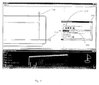
- FIG. 3
- illustrates an exemplary CAD/CAM display with a Step by Step panel
- FIG. 4
- illustrates a dimension extracted from a 3-D model and generated on a 2-D drawing.
- FIG. 5
- illustrates generated dimensions that have been modified by a user.
- FIG. 6
- illustrates deletion of a dimension from a 2-D view that is present in a 3-D model.
- FIG. 7
- illustrates multiple dimensions generated in a single step.
- FIG. 8
- illustrates an exemplary generated dimensions analysis window.
- FIG. 9
- illustrates a programming flow chart of one embodiment of the invention.
- Referring to Fig. 1, physical resources of a
computer system 100 are depicted. Thecomputer 100 has acentral processor 101 connected to a processor host bus 102 over which it provides data, address and control signals. Theprocessors 101 may be any conventional general purpose single-chip or multi-chip microprocessor such as a Pentium series processor, a K6 processor, a MIPS processor, a Power PC processor or an ALPHA processor. In addition, theprocessor 101 may be any conventional special purpose microprocessor such as a digital signal processor or a graphics processor. Themicroprocessor 101 can have conventional address, data, and control lines coupling it to a processor host bus 102. - The
computer 100 can include asystem controller 103 having an integratedRAM memory controller 104. Thesystem controller 103 can be connected to the host bus 102 and provide an interface torandom access memory 105. Thesystem controller 103 can also provide host bus to peripheral bus bridging functions. Thecontroller 103 can thereby permit signals on the processor host bus 102 to be compatibly exchanged with signals on a primary peripheral bus 110. The peripheral bus 110 may be, for example, a Peripheral Component Interconnect (PCI) bus, an Industry Standard Architecture (ISA) bus, or a Micro-Channel bus. Additionally, thecontroller 103 can provide data buffering and data transfer rate matching between the host bus 102 and peripheral bus 110. Thecontroller 103 can thereby allow, for example, aprocessor 101 having a 64-bit 66 MHz interface and a 533 Mbytes/second data transfer rate to interface to a PCI bus 110 having a data path differing in data path bit width, clock speed, or data transfer rate. - Accessory devices including, for example, a hard disk
drive control interface 111 coupled to ahard disk drive 114, avideo display controller 112 coupled to a video display 115, and a keyboard andmouse controller 113 can be coupled to a peripheral bus 110 and controlled by theprocessor 101. The computer system can include a connection to a computer system network, an intranet or an internet. Data and information may be sent and received over such a connection. - The
computer 100 can also include non-volatile ROM memory 107 to store basic computer software routines. ROM 107 may include alterable memory, such as EEPROM (Electronically Erasable Programmable Read Only Memory), to store configuration data.BIOS routines 123 can be included in ROM 107 and provide basic computer initialization, systems testing, and input/output (I/O) services. TheBIOS 123 can also include routines that allow an operating system to be "booted" from thedisk 113. Examples of high-level operating systems are, the Microsoft Windows 98™, Windows NT™, UNIX, the LINUX, the Apple MacOS ™ operating system, or other operating system. - An operating system may be fully loaded in the
RAM memory 105 or may include portions inRAM memory 105,disk drive storage 114, or storage at a network location. The operating system can provide functionality to execute software applications, software systems and tools of software systems. Software functionality can access thevideo display controller 112 or other resources of thecomputer system 100 to provide two dimensional (2-D) and three dimensional (3-D) models on the video computer display 115. - Referring now to Figure 2, a CAD/CAM display screen can include a 3-D model of an object 200 and a
hierarchical tree 240. The hierarchical tree can allow a user to select different 3-D objects. The CAD/CAM screen can also include a 2-D generative drawing 210 corresponding with the selected view of the 3-D drawing. - A dimensions
generation filter panel 230 can also be displayed. The Filter panel can be a pop-up menu or other type window that can be launched to control dimensions or other drawing data generation filter process. TheFilter panel 230 can include a series of check boxes or other user interactive devices that correspond with various options relating to filters for the dimensions or constraints relating to a 2-D generative drawing of 210 the 3-D view 220. - Options that can be included on the Filter panel can include, for example, an option to generate all
dimensions 231, an option to include sketches ofwire frame constraints 232, an option to include 3-Dwire frame constraints 233, an option to include measureddimensions 234, and an option to includedesign tolerances 235. Other options relating to filtering and general control devices can also be programmed into the filter panel. According to user needs, icons or other graphical user interactive devices can also be used to make Filter panel functions available from a desk top. - Referring now to Figure 3, a step-by-step generation panel, a menu, or other type of user interactive window, can be used to facilitate control over dimension generation. A step-by-step generation panel can include icons or other user interactive devices to control the dimension generation. Icons can include, for example, an
arrow icon 311 to issue a start command to begin generation of dimensions. A symbol such as a single arrow can draw upon a user familiarity with a play button on a video or audio control system. Likewise, adouble arrow icon 312 can be used to accelerate the dimension generation process. Astop icon 313 can be used to halt the generation of dimensions. Other options can include adouble bar 314 pause button. Abar graph 330 can be used to graphically illustrate the progression of the dimension generation. In addition, controls can be included to display a visualization indimensions 315. An incremental window can also be included for setting the duration of the time-out 316. The time-out sets the amount of time a user has to intervene between steps of dimension generation. A higher time-out number can provide more time between generation of successive dimensions included on the 2-D generative drawing. A lower time-out number can allow the dimension generation process to proceed more quickly. - Referring now to Figure 4, a dimension can be extracted from a 3-
D model 220 and visualized on the 2-D drawing 210. The dimension can also be visualized on the 3-D model 410. The corresponding dimension on the 2-D model 420, can be displayed if the user elects to generate that drawing data modified by the user or deleted from the present view and/or the 3-D model. - Referring now to Figure 5, during extraction of drawing data from a 3-
D model 220 and generation of the data to 2-D model 210, a user can halt the generation process to perform a modification to the dimension being generated. For example, as a dimension is generated, a user can press apause button 314. Thepause button 314 can halt a time-out clock from running. While dimension generation is halted, a user can modify the content, appearance or location of a dimension generated such as 510 and 511. Modifications can include, for example, changing the font or text of the constraint generated, enhancing the text with bold, italics, underline or other text enhancements, changing the content of the text, or deleting a part of or the entire text of the dimension generated. The position of the generated dimensions can also be changed. In this manner, a user can place a dimension in a different area of a 2-D drawing. - Referring now to Figure 6, step-by-step dimension generation can also allow for deletion of a particular dimension. Deletion of a dimension can prevent the dimension from being generated even if it could be displayed in another view of the generative drafting. In this manner a user can efficiently remove unwanted dimensions from all views of the generative drafting. A dimension deleted from the 2-
D drawing 611 can still be seen in the 3-D model 612. - Referring now to Figure 7, a fast
forward control device 312 on the step-by-step panel 310 can be used to accelerate dimension generation. Activation of afast forward button 312 enables a user to generate several dimensions, constraints, or other drawing data in a single step. In one embodiment, twoconstraints step bar graph 330. - Referring now to Figure 8, a user can stop dimension extraction and drawing data generation or allow all dimensions to generate to a point at which the generation process stops. After the dimension generation process has stopped, a generated
dimensions analysis window 800, or other graphical display, can be used to display the generated results. The generateddimensions analysis window 800 can include, for example, the number of constraints on the 3-D Model 810 and the number dimensions associated with constraints generated to the 2-D drawings 811. In addition, the generateddimensions analysis window 800 can include check boxes or other user interactive devices to control the display results such as the constraints on the 3-D modest associated with the generateddimensions 812, constraints other then those associated with the generateddimension 813, or excludedconstraints 814. These options can be included in a constraints analysis section of the generated dimension analysis window. A dimensions analysis section can include, for example, a check box for new generateddimensions 815, a check box for call generateddimensions 816 and a check box forother dimensions 817. Other options, statistics or graphical representations relating to the dimensions generated can also be included in the generateddimensions analysis menu 800. - Referring now to Figure 9, an exemplary flow chart of one embodiment can include for example, a
program initialization stage 910 wherein a user can filter specifications to be processed during dimension generation. Specifications can include, for example, constraints 3-DW including 3-D offset between planes and 2-D numerical data in plane or Features Parameters such as, for example, a whole diameter or a drawing and its views. A user may choose to generate dimensions in asemi-automatic mode 911. A "No" response to a semi-automatic mode can allow a user to chooseautomatic mode 912. A subsequent "No" response to automatic mode can allow the user to exit theprogram 950. A "Yes" response toautomatic mode 912 can cause the program to extract all 3-D constraints 913 and generate drawingdata 914. - A "Yes" response to
semi-automatic mode 911 can allow a user to specify step-by-step mode 915. If a user chooses not to run in step-by-step mode they can be asked to define atimeout 916. The program can then proceed to extract a constraint from the 3-D view 917 and query whether the constraint has already been processed 918. If the constraint has not been processed 918, the program can generatedrawing data 919. If the timeout has expired 920 before a user has intervened by pressing a pause button 921, the program can loop around and extract another constraint from the 3-D view 917. If a user has activated a pause button or other interactive device 921 programmed to pause the process, the user can be prompted to modify generateddrawing data 922. The user can also opt to make modifications on generated drawingdata 923 and store amodifications 924. After storing the modification, or if the user opts not to modify generated drawingdata 922, the user can be prompted as to whether they would like to continue 925. If a user wishes to continue 925 he can also be allowed to branch toautomatic mode 926. If the user does not branch toautomatic mode 926, the program can loop and extract a next constraint from the 3-D view 917. If a user does opt to branch toautomatic mode 926 the program can proceed to extract all remaining 3-D constraints 913 and generate drawingdata 914 before exiting 950. - Choosing to proceed with step-by-
step processing 915 can allow the program to extract a constraint from the 3-D view 927 and query whether that constraint has already been processed 928. If the constraint has not been processed, the program can generatedrawing data 929. If the constraint has already been processed, the user can be prompted to modify generateddrawing data 930. If the user opts not to modify generated drawing data, the system can ask if the user wishes to continue 933. Indicating that a user does not wish to continue 933 can cause the program to exit 950. Indicating that a user does wish to continue 933 can allow a user to chooseautomatic mode 934. Choosingautomatic mode 934 can cause the program to extract allconstraints 913 and generate drawingdata 914 before the program exits 950. Not choosingautomatic mode 934 can cause the program to loop back and extract anext constraint 927, thereby processing each constraint in a similar fashion. - The invention may be implemented in digital electronic circuitry, or in computer hardware, firmware, software, or in combinations of them. Apparatus of the invention may be implemented in a computer program product tangibly embodied in a machine-readable storage device for execution by a programmable processor; and method steps of the invention may be performed by a programmable processor executing a program of instructions to perform functions of the invention by operating on input data and generating output.
- The invention may advantageously be implemented in one or more computer programs that are executable on a programmable system, including at least one programmable processor coupled to receive data and instructions from, and to transmit data and instructions to, a memory storage system, at least one input device, and at least one output device. Each computer program may be implemented in a high-level procedural or object-oriented programming language, or in assembly or machine language if desired; and in any case, the language may be a compiled or interpreted language.
- Generally, a processor can receive instructions and data from a read-only memory and/or a random access memory. Storage devices suitable for tangibly embodying computer program instructions and data include all forms of non-volatile memory, including, by way of example, semiconductor memory devices, such as EPROM, EEPROM, and flash memory devices; magnetic disks such as internal hard disks and removable disks; magneto-optical disks; and CD-ROM disks. Any of the foregoing may be supplemented by, or incorporated in, specially-designed ASICs (application-specific integrated circuits).
- A number of embodiments of the present invention have been described. It can be understood that various modifications may be made without departing from the spirit and scope of the invention. Therefore, other implementations are within the scope of the following claims.
Claims (23)
- A software control method comprising:forming a two dimensional view of a computer defined graphical model;generating a drawing data item associated with a component of the two dimensional view;forming a user interface for controlling the addition of the drawing data item to the two dimensional view;adding the drawing data item to the two dimensional view responsive to activation of a user interactive device comprising the user interface.
- The software control method of claim 1 wherein the drawing data item is a dimension.
- The software control method of claim 1 wherein a drawing data item is added to the two dimensional view semi-automatically responsive to the expiration of a predetermined time-out period and in the absence of an intervening user action.
- The software control method of claim 3 wherein the intervening action comprises activation of a pause button.
- The software control method of claim 1 additionally comprising the step of modifying the drawing data item.
- The software control method of claim 1 additionally comprising the step of deleting the drawing data item such that the item will not appear in subsequent two dimensional views of the computer defined model.
- The software control method of claim 1 additionally comprising the step of stopping the generation of drawing data items and forming an additional two dimensional view.
- The software control method of claim 7 wherein a modification of a drawing data item is reproduced in a subsequently formed two dimensional view.
- The software control method of claim 1 additionally comprising selecting between an automatic or semi-automatic mode of drawing data generation, wherein selecting an automatic mode causes the software to branch and generate drawing data without requiring the formation of a user interface for controlling the addition of a subsequent drawing data item to the two dimensional view and adds the drawing data item to the two dimensional view without requiring activation of a user interactive device.
- The software control method of claim 9 wherein a semi-automatic mode comprises a time-out period during which a user can activate a user interactive device causing the drawing data generation process to be paused.
- The software control method of claim 10 additionally comprising the step of modifying drawing data while the generation process is paused.
- The software control method of claim 10 additionally comprising the step of automatically generating additional drawing data following modification of drawing data.
- The software control method of claim 1 additionally comprising the step of filtering particular drawing data from the two dimensional view.
- The software control method of claim 1 additionally comprising the step of filtering particular two dimensional views from being formed.
- A computer system for controlling generation of drawing data relating to a two dimensional view of a computer defined model, the system comprising:a processor operatively interconnected to a memory;a user input device;a display; anda graphical user interface comprising user interactive devices wherein the system is responsive to activation of the user interactive devices by causing a semi-automatic mode of transfer of drawing data associated with the two dimensional view.
- The computer system of claim 15 wherein the drawing data comprises a dimension.
- The computer system of claim 15 wherein the drawing data is added to the two dimensional view semi-automatically responsive to the expiration of a predetermined time-out period without an intervening user action.
- A computer program residing on a computer-readable medium, the program comprising instructions for causing a computer to:form a two dimensional view of a computer defined graphical model;generate a drawing data item associated with a component of the two dimensional view;form a user interface for controlling the addition of the drawing data item to the two dimensional view;add the drawing data item to the two dimensional view responsive to activation of a user interactive device comprising the user interface.
- A method of interacting with a computer so as to add drawing data to a two dimensional view of an object, the method comprising:launching an application which includes a command to add drawing data in a semi-automatic mode;extracting drawing data from a three dimensional model;generating the drawing data on the two dimensional view; andmodifying the generated drawing data.
- The method of claim 19 additionally comprising the step of storing the modified drawing data.
- A method of interacting with a computer so as to add drawing data to a two dimensional view of an object, the method comprising:launching an application which includes a command to add drawing data in a semi-automatic mode;defining a timeout period;extracting drawing data from a three dimensional model;generating the drawing data on the two dimensional view;pausing the extraction of data from the three dimensional model; and modifying the generated drawing data.
- A programmed computer for adding drawing data to a two dimensional view of an object comprising:a memory having at least one region for storing computer software code;a processor operatively interconnected to the memory for executing software code stored in the memory, wherein the software code causes the computer to:display a first user interactive interface for selecting specified drawing data, a drawing and selected views of the drawing;display a second user interactive interface for selecting between an automatic and semi-automatic mode of generating drawing data;display a third user interactive interface for selecting step-by-step processing or time-out processing of drawing data;generate drawing data;allow user modification of the drawing data;store modified drawing data; andadd the drawing data to the two dimensional view.
- The programmed computer of claim 22 wherein the software code additionally causes the computer to:display a fourth user interactive interface with a user interactive device for entering a time-out period; andan interactive user device for pausing the generation of drawing data, whereby a user can modify the drawing data during the pause.
Applications Claiming Priority (2)
| Application Number | Priority Date | Filing Date | Title |
|---|---|---|---|
| US09/329,923 US6918095B1 (en) | 1999-06-10 | 1999-06-10 | Dimension generation filter and analysis |
| US329923 | 1999-06-10 |
Publications (3)
| Publication Number | Publication Date |
|---|---|
| EP1059616A2 true EP1059616A2 (en) | 2000-12-13 |
| EP1059616A3 EP1059616A3 (en) | 2004-05-26 |
| EP1059616B1 EP1059616B1 (en) | 2012-02-29 |
Family
ID=23287600
Family Applications (1)
| Application Number | Title | Priority Date | Filing Date |
|---|---|---|---|
| EP00401390A Expired - Lifetime EP1059616B1 (en) | 1999-06-10 | 2000-05-19 | Method and apparatus for generation the dimensions of a 3D model |
Country Status (6)
| Country | Link |
|---|---|
| US (1) | US6918095B1 (en) |
| EP (1) | EP1059616B1 (en) |
| JP (1) | JP3939901B2 (en) |
| AT (1) | ATE547777T1 (en) |
| CA (1) | CA2305066C (en) |
| DE (1) | DE1059616T1 (en) |
Families Citing this family (4)
| Publication number | Priority date | Publication date | Assignee | Title |
|---|---|---|---|---|
| GB0228973D0 (en) * | 2002-12-12 | 2003-01-15 | Univ Aston | System and method for coding and retrieval of a CAD drawing from a database |
| JP4547990B2 (en) * | 2004-05-25 | 2010-09-22 | 富士ゼロックス株式会社 | Information processing apparatus and information processing program |
| US7561996B2 (en) * | 2006-01-13 | 2009-07-14 | Chrysler Llc | Automated dimensional drawing generating apparatus |
| US20150347366A1 (en) * | 2014-05-28 | 2015-12-03 | Siemens Product Lifecycle Management Software Inc. | Creation of associative 3d product documentation from drawing annotation |
Citations (5)
| Publication number | Priority date | Publication date | Assignee | Title |
|---|---|---|---|---|
| GB2255661A (en) * | 1991-04-30 | 1992-11-11 | Tecnocad Limited | Design of articles having inter-related parts |
| US5202961A (en) * | 1990-06-08 | 1993-04-13 | Apple Computer, Inc. | Sequential information controller |
| US5548706A (en) * | 1992-09-29 | 1996-08-20 | Fujitsu Limited | CAD system with parallel dimension-line editing function |
| US5655095A (en) * | 1993-11-09 | 1997-08-05 | Adra Systems, Inc. | Method and sysetm for design and drafting |
| US5692115A (en) * | 1993-04-02 | 1997-11-25 | Hitachi, Ltd. | Method of generating an image and an apparatus for carrying out such a method |
Family Cites Families (21)
| Publication number | Priority date | Publication date | Assignee | Title |
|---|---|---|---|---|
| US5603318A (en) * | 1992-04-21 | 1997-02-18 | University Of Utah Research Foundation | Apparatus and method for photogrammetric surgical localization |
| JP3221086B2 (en) * | 1992-09-17 | 2001-10-22 | 株式会社日立製作所 | Heterogeneous mechanical parts composite mechanism design system |
| US5544291A (en) * | 1993-11-10 | 1996-08-06 | Adobe Systems, Inc. | Resolution-independent method for displaying a three dimensional model in two-dimensional display space |
| US5687305A (en) * | 1994-03-25 | 1997-11-11 | General Electric Company | Projection of images of computer models in three dimensional space |
| JP3333319B2 (en) * | 1994-06-03 | 2002-10-15 | 三菱電機株式会社 | 2D and 3D integrated CAD system |
| JPH08287288A (en) * | 1995-03-24 | 1996-11-01 | Internatl Business Mach Corp <Ibm> | Plurality of side annotations interactive three-dimensional graphics and hot link |
| US5729673A (en) * | 1995-04-07 | 1998-03-17 | Avid Technology, Inc. | Direct manipulation of two-dimensional moving picture streams in three-dimensional space |
| JP3245336B2 (en) * | 1995-09-29 | 2002-01-15 | 富士通株式会社 | Modeling method and modeling system |
| EP1426910A3 (en) * | 1996-04-16 | 2006-11-02 | Xanavi Informatics Corporation | Map display device, navigation device and map display method |
| US6308144B1 (en) * | 1996-09-26 | 2001-10-23 | Computervision Corporation | Method and apparatus for providing three-dimensional model associativity |
| KR20000064776A (en) * | 1997-01-24 | 2000-11-06 | 이데이 노부유끼 | Apparatus for generating a shape data, a method for generating the shape data, and a medium thereof |
| IL120136A0 (en) * | 1997-02-03 | 1997-06-10 | Yissum Res Dev Co | Synthesizing virtual two dimensional images of three dimensional space from a collection of real two dimensional images |
| US6124864A (en) * | 1997-04-07 | 2000-09-26 | Synapix, Inc. | Adaptive modeling and segmentation of visual image streams |
| US5857032A (en) * | 1997-04-25 | 1999-01-05 | General Electric Company | System and method for measuring and monitoring three-dimensional shaped objects |
| US6492986B1 (en) * | 1997-06-02 | 2002-12-10 | The Trustees Of The University Of Pennsylvania | Method for human face shape and motion estimation based on integrating optical flow and deformable models |
| US5990897A (en) * | 1997-09-12 | 1999-11-23 | Hanratty; Patrick J. | Methods for automatically generating a three-dimensional geometric solid from two-dimensional view sets including automatic segregation of open, closed and disjoint curves into views using their center of gravity |
| US6542937B1 (en) * | 1998-02-27 | 2003-04-01 | Amada Company, Limited | Apparatus and method for transferring and editing sheet metal part data |
| US6137491A (en) * | 1998-06-05 | 2000-10-24 | Microsoft Corporation | Method and apparatus for reconstructing geometry using geometrically constrained structure from motion with points on planes |
| US6281903B1 (en) * | 1998-12-04 | 2001-08-28 | International Business Machines Corporation | Methods and apparatus for embedding 2D image content into 3D models |
| US6771260B1 (en) * | 1999-12-13 | 2004-08-03 | Amada Company, Limited | Sketcher |
| US6775581B2 (en) * | 2001-03-14 | 2004-08-10 | Delphi Technologies, Inc. | Horizontally-structured CAD/CAM modeling for virtual concurrent product and process design |
-
1999
- 1999-06-10 US US09/329,923 patent/US6918095B1/en not_active Expired - Lifetime
-
2000
- 2000-04-12 CA CA002305066A patent/CA2305066C/en not_active Expired - Lifetime
- 2000-05-19 EP EP00401390A patent/EP1059616B1/en not_active Expired - Lifetime
- 2000-05-19 DE DE1059616T patent/DE1059616T1/en active Pending
- 2000-05-19 AT AT00401390T patent/ATE547777T1/en active
- 2000-06-09 JP JP2000173621A patent/JP3939901B2/en not_active Expired - Lifetime
Patent Citations (5)
| Publication number | Priority date | Publication date | Assignee | Title |
|---|---|---|---|---|
| US5202961A (en) * | 1990-06-08 | 1993-04-13 | Apple Computer, Inc. | Sequential information controller |
| GB2255661A (en) * | 1991-04-30 | 1992-11-11 | Tecnocad Limited | Design of articles having inter-related parts |
| US5548706A (en) * | 1992-09-29 | 1996-08-20 | Fujitsu Limited | CAD system with parallel dimension-line editing function |
| US5692115A (en) * | 1993-04-02 | 1997-11-25 | Hitachi, Ltd. | Method of generating an image and an apparatus for carrying out such a method |
| US5655095A (en) * | 1993-11-09 | 1997-08-05 | Adra Systems, Inc. | Method and sysetm for design and drafting |
Non-Patent Citations (1)
| Title |
|---|
| ROY U ET AL: "REVIEW OF DIMENSIONING AND TOLERANCING: REPRESENTATION AND PROCESSING" COMPUTER AIDED DESIGN, ELSEVIER PUBLISHERS BV., BARKING, GB, vol. 23, no. 7, 1 September 1991 (1991-09-01), pages 466-483, XP000236525 ISSN: 0010-4485 * |
Also Published As
| Publication number | Publication date |
|---|---|
| JP2001052042A (en) | 2001-02-23 |
| JP3939901B2 (en) | 2007-07-04 |
| CA2305066A1 (en) | 2000-12-10 |
| EP1059616A3 (en) | 2004-05-26 |
| EP1059616B1 (en) | 2012-02-29 |
| US6918095B1 (en) | 2005-07-12 |
| DE1059616T1 (en) | 2001-10-25 |
| ATE547777T1 (en) | 2012-03-15 |
| CA2305066C (en) | 2009-12-22 |
Similar Documents
| Publication | Publication Date | Title |
|---|---|---|
| US5815154A (en) | Graphical browser system for displaying and manipulating a computer model | |
| EP1785853B1 (en) | System and method for creation of an object within an object hierarchy structure | |
| US6219055B1 (en) | Computer based forming tool | |
| CN1105964C (en) | Method for displaying functional objects in visual programming | |
| EP0745927B1 (en) | Method of and editing system for setting tool button | |
| JPH01200480A (en) | Control of computer graphic system | |
| EP1071014B1 (en) | Adding code in an application during runtime to enrich object behavior | |
| EP1059616B1 (en) | Method and apparatus for generation the dimensions of a 3D model | |
| US7554544B2 (en) | Just-in-time user interface layout | |
| CN107491311B (en) | Method and system for generating page file and computer equipment | |
| CN107562476B (en) | Method and device for generating application program | |
| WO2000019381A9 (en) | Mate inferencing system | |
| US20220180011A1 (en) | Systems and methods for modifying cad files | |
| US20220358258A1 (en) | Computer-aided design methods and systems | |
| US20070094639A1 (en) | Preparing assembly languague source code | |
| CN109814857B (en) | Method and device for customizing primitive linkage | |
| JP2875135B2 (en) | Program device for programmable controller | |
| JP3486607B2 (en) | System development method and apparatus, and recording medium | |
| CN114241079A (en) | Automatic generation method and device of bank system architecture diagram | |
| CN114200885A (en) | Programming method and device applied to programmable logic controller | |
| CN117547828A (en) | Game skill generating method, terminal device and computer readable storage medium | |
| CN114019822A (en) | Intelligent household equipment control method, device, equipment and storage medium | |
| JP3358266B2 (en) | Animation creation device | |
| CN117744398A (en) | Simulation method, simulation system, simulation device and storage medium for modeling software | |
| CN117667055A (en) | Low-code digital twin scene interaction configuration method and system |
Legal Events
| Date | Code | Title | Description |
|---|---|---|---|
| PUAI | Public reference made under article 153(3) epc to a published international application that has entered the european phase |
Free format text: ORIGINAL CODE: 0009012 |
|
| AK | Designated contracting states |
Kind code of ref document: A2 Designated state(s): AT BE CH CY DE DK ES FI FR GB GR IE IT LI LU MC NL PT SE |
|
| AX | Request for extension of the european patent |
Free format text: AL;LT;LV;MK;RO;SI |
|
| EL | Fr: translation of claims filed | ||
| DET | De: translation of patent claims | ||
| PUAL | Search report despatched |
Free format text: ORIGINAL CODE: 0009013 |
|
| AK | Designated contracting states |
Kind code of ref document: A3 Designated state(s): AT BE CH CY DE DK ES FI FR GB GR IE IT LI LU MC NL PT SE |
|
| AX | Request for extension of the european patent |
Extension state: AL LT LV MK RO SI |
|
| RIC1 | Information provided on ipc code assigned before grant |
Ipc: 7G 06T 17/40 B Ipc: 7G 06T 17/00 A |
|
| 17P | Request for examination filed |
Effective date: 20040701 |
|
| 17Q | First examination report despatched |
Effective date: 20041005 |
|
| AKX | Designation fees paid |
Designated state(s): AT BE CH CY DE DK ES FI FR GB GR IE IT LI LU MC NL PT SE |
|
| REG | Reference to a national code |
Ref country code: HK Ref legal event code: WD Ref document number: 1031775 Country of ref document: HK |
|
| GRAP | Despatch of communication of intention to grant a patent |
Free format text: ORIGINAL CODE: EPIDOSNIGR1 |
|
| RIN1 | Information on inventor provided before grant (corrected) |
Inventor name: MOUKY, ALAIN Inventor name: AGNES, FABRICE |
|
| GRAS | Grant fee paid |
Free format text: ORIGINAL CODE: EPIDOSNIGR3 |
|
| GRAA | (expected) grant |
Free format text: ORIGINAL CODE: 0009210 |
|
| AK | Designated contracting states |
Kind code of ref document: B1 Designated state(s): AT BE CH CY DE DK ES FI FR GB GR IE IT LI LU MC NL PT SE |
|
| REG | Reference to a national code |
Ref country code: GB Ref legal event code: FG4D Ref country code: CH Ref legal event code: EP |
|
| RIC1 | Information provided on ipc code assigned before grant |
Ipc: G06T 19/00 20110101ALI20120125BHEP Ipc: G06T 17/00 20060101AFI20120125BHEP |
|
| REG | Reference to a national code |
Ref country code: DE Ref legal event code: R081 Ref document number: 60046961 Country of ref document: DE Owner name: DASSAULT SYSTEMES S.E., FR Free format text: FORMER OWNER: DASSAULT SYSTEMES, SURESNES, FR |
|
| REG | Reference to a national code |
Ref country code: AT Ref legal event code: REF Ref document number: 547777 Country of ref document: AT Kind code of ref document: T Effective date: 20120315 |
|
| REG | Reference to a national code |
Ref country code: IE Ref legal event code: FG4D |
|
| REG | Reference to a national code |
Ref country code: DE Ref legal event code: R096 Ref document number: 60046961 Country of ref document: DE Effective date: 20120426 |
|
| REG | Reference to a national code |
Ref country code: SE Ref legal event code: TRGR |
|
| REG | Reference to a national code |
Ref country code: NL Ref legal event code: VDEP Effective date: 20120229 |
|
| PG25 | Lapsed in a contracting state [announced via postgrant information from national office to epo] |
Ref country code: NL Free format text: LAPSE BECAUSE OF FAILURE TO SUBMIT A TRANSLATION OF THE DESCRIPTION OR TO PAY THE FEE WITHIN THE PRESCRIBED TIME-LIMIT Effective date: 20120229 |
|
| PG25 | Lapsed in a contracting state [announced via postgrant information from national office to epo] |
Ref country code: PT Free format text: LAPSE BECAUSE OF FAILURE TO SUBMIT A TRANSLATION OF THE DESCRIPTION OR TO PAY THE FEE WITHIN THE PRESCRIBED TIME-LIMIT Effective date: 20120629 Ref country code: BE Free format text: LAPSE BECAUSE OF FAILURE TO SUBMIT A TRANSLATION OF THE DESCRIPTION OR TO PAY THE FEE WITHIN THE PRESCRIBED TIME-LIMIT Effective date: 20120229 Ref country code: GR Free format text: LAPSE BECAUSE OF FAILURE TO SUBMIT A TRANSLATION OF THE DESCRIPTION OR TO PAY THE FEE WITHIN THE PRESCRIBED TIME-LIMIT Effective date: 20120530 Ref country code: FI Free format text: LAPSE BECAUSE OF FAILURE TO SUBMIT A TRANSLATION OF THE DESCRIPTION OR TO PAY THE FEE WITHIN THE PRESCRIBED TIME-LIMIT Effective date: 20120229 |
|
| REG | Reference to a national code |
Ref country code: AT Ref legal event code: MK05 Ref document number: 547777 Country of ref document: AT Kind code of ref document: T Effective date: 20120229 |
|
| PG25 | Lapsed in a contracting state [announced via postgrant information from national office to epo] |
Ref country code: CY Free format text: LAPSE BECAUSE OF FAILURE TO SUBMIT A TRANSLATION OF THE DESCRIPTION OR TO PAY THE FEE WITHIN THE PRESCRIBED TIME-LIMIT Effective date: 20120229 |
|
| PG25 | Lapsed in a contracting state [announced via postgrant information from national office to epo] |
Ref country code: DK Free format text: LAPSE BECAUSE OF FAILURE TO SUBMIT A TRANSLATION OF THE DESCRIPTION OR TO PAY THE FEE WITHIN THE PRESCRIBED TIME-LIMIT Effective date: 20120229 |
|
| PG25 | Lapsed in a contracting state [announced via postgrant information from national office to epo] |
Ref country code: MC Free format text: LAPSE BECAUSE OF NON-PAYMENT OF DUE FEES Effective date: 20120531 |
|
| REG | Reference to a national code |
Ref country code: CH Ref legal event code: PL |
|
| PLBE | No opposition filed within time limit |
Free format text: ORIGINAL CODE: 0009261 |
|
| STAA | Information on the status of an ep patent application or granted ep patent |
Free format text: STATUS: NO OPPOSITION FILED WITHIN TIME LIMIT |
|
| PG25 | Lapsed in a contracting state [announced via postgrant information from national office to epo] |
Ref country code: LI Free format text: LAPSE BECAUSE OF NON-PAYMENT OF DUE FEES Effective date: 20120531 Ref country code: CH Free format text: LAPSE BECAUSE OF NON-PAYMENT OF DUE FEES Effective date: 20120531 Ref country code: AT Free format text: LAPSE BECAUSE OF FAILURE TO SUBMIT A TRANSLATION OF THE DESCRIPTION OR TO PAY THE FEE WITHIN THE PRESCRIBED TIME-LIMIT Effective date: 20120229 |
|
| 26N | No opposition filed |
Effective date: 20121130 |
|
| REG | Reference to a national code |
Ref country code: IE Ref legal event code: MM4A |
|
| REG | Reference to a national code |
Ref country code: DE Ref legal event code: R097 Ref document number: 60046961 Country of ref document: DE Effective date: 20121130 |
|
| PG25 | Lapsed in a contracting state [announced via postgrant information from national office to epo] |
Ref country code: IE Free format text: LAPSE BECAUSE OF NON-PAYMENT OF DUE FEES Effective date: 20120519 Ref country code: ES Free format text: LAPSE BECAUSE OF FAILURE TO SUBMIT A TRANSLATION OF THE DESCRIPTION OR TO PAY THE FEE WITHIN THE PRESCRIBED TIME-LIMIT Effective date: 20120609 |
|
| PG25 | Lapsed in a contracting state [announced via postgrant information from national office to epo] |
Ref country code: LU Free format text: LAPSE BECAUSE OF NON-PAYMENT OF DUE FEES Effective date: 20120519 |
|
| REG | Reference to a national code |
Ref country code: FR Ref legal event code: PLFP Year of fee payment: 17 |
|
| REG | Reference to a national code |
Ref country code: FR Ref legal event code: PLFP Year of fee payment: 18 |
|
| REG | Reference to a national code |
Ref country code: DE Ref legal event code: R082 Ref document number: 60046961 Country of ref document: DE Representative=s name: HORN KLEIMANN WAITZHOFER PATENTANWAELTE PARTG , DE Ref country code: DE Ref legal event code: R081 Ref document number: 60046961 Country of ref document: DE Owner name: DASSAULT SYSTEMES S.E., FR Free format text: FORMER OWNER: DASSAULT SYSTEMES, SURESNES, FR |
|
| REG | Reference to a national code |
Ref country code: FR Ref legal event code: PLFP Year of fee payment: 19 |
|
| PGFP | Annual fee paid to national office [announced via postgrant information from national office to epo] |
Ref country code: DE Payment date: 20190521 Year of fee payment: 20 Ref country code: IT Payment date: 20190527 Year of fee payment: 20 |
|
| PGFP | Annual fee paid to national office [announced via postgrant information from national office to epo] |
Ref country code: SE Payment date: 20190521 Year of fee payment: 20 Ref country code: FR Payment date: 20190522 Year of fee payment: 20 |
|
| PGFP | Annual fee paid to national office [announced via postgrant information from national office to epo] |
Ref country code: GB Payment date: 20190521 Year of fee payment: 20 |
|
| REG | Reference to a national code |
Ref country code: DE Ref legal event code: R071 Ref document number: 60046961 Country of ref document: DE |
|
| REG | Reference to a national code |
Ref country code: GB Ref legal event code: PE20 Expiry date: 20200518 |
|
| REG | Reference to a national code |
Ref country code: SE Ref legal event code: EUG |
|
| PG25 | Lapsed in a contracting state [announced via postgrant information from national office to epo] |
Ref country code: GB Free format text: LAPSE BECAUSE OF EXPIRATION OF PROTECTION Effective date: 20200518 |
|
| P01 | Opt-out of the competence of the unified patent court (upc) registered |
Effective date: 20230527 |