EP1053790A2 - Improved multi-well plates. - Google Patents
Improved multi-well plates. Download PDFInfo
- Publication number
- EP1053790A2 EP1053790A2 EP00304232A EP00304232A EP1053790A2 EP 1053790 A2 EP1053790 A2 EP 1053790A2 EP 00304232 A EP00304232 A EP 00304232A EP 00304232 A EP00304232 A EP 00304232A EP 1053790 A2 EP1053790 A2 EP 1053790A2
- Authority
- EP
- European Patent Office
- Prior art keywords
- well plate
- plate
- section line
- well
- lugs
- Prior art date
- Legal status (The legal status is an assumption and is not a legal conclusion. Google has not performed a legal analysis and makes no representation as to the accuracy of the status listed.)
- Granted
Links
Images

Classifications
-
- B—PERFORMING OPERATIONS; TRANSPORTING
- B01—PHYSICAL OR CHEMICAL PROCESSES OR APPARATUS IN GENERAL
- B01L—CHEMICAL OR PHYSICAL LABORATORY APPARATUS FOR GENERAL USE
- B01L3/00—Containers or dishes for laboratory use, e.g. laboratory glassware; Droppers
- B01L3/50—Containers for the purpose of retaining a material to be analysed, e.g. test tubes
- B01L3/508—Containers for the purpose of retaining a material to be analysed, e.g. test tubes rigid containers not provided for above
- B01L3/5085—Containers for the purpose of retaining a material to be analysed, e.g. test tubes rigid containers not provided for above for multiple samples, e.g. microtitration plates
-
- Y—GENERAL TAGGING OF NEW TECHNOLOGICAL DEVELOPMENTS; GENERAL TAGGING OF CROSS-SECTIONAL TECHNOLOGIES SPANNING OVER SEVERAL SECTIONS OF THE IPC; TECHNICAL SUBJECTS COVERED BY FORMER USPC CROSS-REFERENCE ART COLLECTIONS [XRACs] AND DIGESTS
- Y10—TECHNICAL SUBJECTS COVERED BY FORMER USPC
- Y10T—TECHNICAL SUBJECTS COVERED BY FORMER US CLASSIFICATION
- Y10T428/00—Stock material or miscellaneous articles
- Y10T428/15—Sheet, web, or layer weakened to permit separation through thickness
Definitions
- the present invention relates generally to containers for holding liquids, reagents, and materials, for testing, analytical procedures, and performance of chemical reactions. It is particularly applicable, but in no way limited, to multi-well plates.
- Multi-well plates or two-dimensionally bound arrays of wells or reaction chambers, are commonly employed in research and clinical procedures for the screening and evaluation of multiple samples.
- Multi-well plates are especially useful in conjunction with automated thermal cyclers for performing the widely used polymerase chain reaction, or "PCR", and for DNA cycle sequencing and the like. They are also highly useful for biological micro-culturing and assay procedures, and for performing chemical syntheses on a micro scale.
- Multi-well plates may have wells or tubes that have single openings at their top ends, similar to conventional test tubes and centrifuge tubes, or they may incorporate second openings at their bottom ends which are fitted with frits or filter media to provide a filtration capability. As implied above, multi-well plates are most often used for relatively small scale laboratory procedures and are therefore also commonly known as "microplates”.
- Multi-well plates for PCR use are typically comprised of a plurality of plastic tubes arranged in rectangular planar arrays of typically 3 x 8 (a 24 well plate), 6 x 8 (a 48 well plate) or 8 x 12 (a 96 well plate) tubes with an industry standard 9 mm (0.35 in.) centre-to centre tube spacing (or fractions thereof).
- 3 x 8 a 24 well plate
- 6 x 8 a 48 well plate
- 8 x 12 a 96 well plate
- a horizontally disposed tray or plate portion generally extends integrally between each tube, interconnecting each tube with its neighbour in a cross-web fashion.
- the bottoms of the tubes may be of a rounded conical shape (as generally used for thermal cycling and to ensure complete transfer of samples), or they may be flat-bottomed (typical with either round or square-shaped designs used with optical readers).
- Multi-well “plates” may also exist in a "strip" form wherein a single planar row of interconnected tubes is provided.
- thermal cyclers that are presently available have heating/cooling blocks with conically shaped depressions, typically 96 in number, which are specifically designed and arrayed for mateably receiving the lower portion of the tubes of multi-well plates so that intimate and uniform heating of the PCR reaction mixtures contained within the wells (tubes) may occur.
- pre-selecting plate blocks requires considerable pre-planning and also presupposes the results of the first set of reactions. Once chosen, there is no subsequent flexibility as to the number in each block. In addition, this method greatly increases the number of manual handling operations since each block must be picked up separately. Furthermore, these smaller blocks are generally not amenable to robotic handling, whilst conventional 96 and 384 multi-well plates are routinely handled robotically.
- a multi-well plate comprising a plurality of discrete tubes held together in an array by a plate portion, characterised in that one or more section lines are provided in the plate portion in pre-determined regions, said section lines being adapted to facilitate dividing up the multi-well plate into sub-units of a pre-determined size.
- Forming section lines in the plate either during the moulding process or subsequently, enables the operator to divide the plate into smaller sub-units which will still fit together side by side in a thermal cycler or the like.
- section lines are formed by a score line extending across the width of the plate.
- a score line is defined as any feature which facilitates the separation of the plate into sub-units.
- the section line or score line comprises one or more apertures extending through the thickness of the plate portion.
- the plate can easily be separated into sub-units.
- the section line incorporates one or more lugs connecting adjacent sub-units.
- the lugs are of a snap-off construction, such that the lugs associated with a section line can be removed in the event that plate is divided into sub-units along that section line.
- the lugs provide the plate with rigidity when it is in its original configuration before subdivision. However, the lugs are easily removed when the plate is subdivided.
- the lugs may be substantially circular regions which extend across the section line. They may be partially punched out or weakened around their circumference for ease of removal.
- section line may comprise a pull-out strip or a series of perforations.
- the plate incorporates a skirt around the perimeter of the plate in order to increase the rigidity of the plate.
- the skirt also provides space upon which to label the plate and its individual sub-units.
- the skirt incorporates gaps at strategic points to facilitate robotic handling.
- each tube in the multi-well plate extends proud of the plate portion.
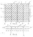
- Figure 1A this illustrates a plan view of a 96 well plate according to a first embodiment of the invention.
- Figure 1A shows a 96 well plate 10 consisting of 96 wells 11 held in a fixed configuration by a plate portion 12.
- the plate portion is a substantially flat, substantially continuous rectangular sheet of plastics material abutting and surrounding each well.
- the wells are positioned in the plate portion such that only a rim 13 of each well projects above the top of the plate portion with the multi-well plate in its normal orientation in use.
- the rims 13 are designed to form a better contact with any seal placed over the plate.
- Such sealing methods include micromats, adhesive sealing sheets or foils.
- these rims are not an essential feature of the present invention. They simply improve the performance of the plates when they have to be sealed.
- a skirt is formed around the plate 10 by depending edges 14 - 17 inclusive of the plate portion.
- This skirt serves a number of functions. It increases the rigidity of the multi-well plate. It also provides apertures 18, 19 for the fingers of a robot to permit robotic handling of the plates. Similar apertures (not shown) are provided in the other edges of the plate.
- the skirt provides a useful surface on which to label the plate to record its contents and any reaction sequences.
- the slits extend substantially entirely across the width of the plate there obviously must be certain regions where connection is made between adjacent sub-units.
- the plate can be snapped by bending it about the widthwise slots.
- the end portions 32 and 33 are also detachable in the same way.
- connections between adjacent sub-units can be formed by substantially circular regions as shown in Figure 1, which are partially punched out or weakened around their circumference.
- the connecting regions, which extend across the apertures, can then be removed in their entirety simply by snapping them off. This results in the semicircular indentations 30 and 31 shown in Figure 2A.
- the slits 21 to 25 have a finite width.
- the gap between adjacent sub-units is approximately 0.5 mm.
- the space between adjacent wells in a 96 well plate is fixed and the slit cannot therefore exceed this dimension.
- the width of the slit can range from 0.1 mm to 1 mm in a 96 well plate. In other formats wider or narrower slits may be possible.
- a slit or slot is not the only way that this can be achieved.
- section line has a broad meaning in this context and is intended to encompass any construction that can achieve the results described above.
- perforations or a pull-out strip could be used to separate the sub-units as well as a variety of forms of elongate aperture.
- the technology to form perforations, or a series of perforations in a sheet of plastic is well-known to those skilled in the art. When perforations are used it may be necessary to trim off with a knife any excess plastics material between adjacent sub-units.
- multi-well plate in this context also has a broad meaning. This term encompasses an assembly of containers, of whatever size and shape, intended to contain or hold fluid, even on a temporary basis. It is specifically intended to cover plates which have application beyond the PCR application described above.
- plate portion is not limited to a flat sheet-like structure at or near the well rims. It is intended to encompass any connecting structure which holds wells, chambers or other receptacles in place.
Abstract

Description
- The present invention relates generally to containers for holding liquids, reagents, and materials, for testing, analytical procedures, and performance of chemical reactions. It is particularly applicable, but in no way limited, to multi-well plates.
- Multi-well plates, or two-dimensionally bound arrays of wells or reaction chambers, are commonly employed in research and clinical procedures for the screening and evaluation of multiple samples. Multi-well plates are especially useful in conjunction with automated thermal cyclers for performing the widely used polymerase chain reaction, or "PCR", and for DNA cycle sequencing and the like. They are also highly useful for biological micro-culturing and assay procedures, and for performing chemical syntheses on a micro scale.
- Multi-well plates may have wells or tubes that have single openings at their top ends, similar to conventional test tubes and centrifuge tubes, or they may incorporate second openings at their bottom ends which are fitted with frits or filter media to provide a filtration capability. As implied above, multi-well plates are most often used for relatively small scale laboratory procedures and are therefore also commonly known as "microplates".
- Multi-well plates for PCR use are typically comprised of a plurality of plastic tubes arranged in rectangular planar arrays of typically 3 x 8 (a 24 well plate), 6 x 8 (a 48 well plate) or 8 x 12 (a 96 well plate) tubes with an
industry standard 9 mm (0.35 in.) centre-to centre tube spacing (or fractions thereof). As technology has advanced plates with a larger number of wells have been developed such as 16 x 24 (a 384 well plate). A horizontally disposed tray or plate portion generally extends integrally between each tube, interconnecting each tube with its neighbour in a cross-web fashion. In the case of multi-well plates that are of the non-filtration variety, the bottoms of the tubes may be of a rounded conical shape (as generally used for thermal cycling and to ensure complete transfer of samples), or they may be flat-bottomed (typical with either round or square-shaped designs used with optical readers). Multi-well "plates" may also exist in a "strip" form wherein a single planar row of interconnected tubes is provided. - It will be apparent that as many as 96 individual reaction mixtures can be simultaneously subjected to, for example, PCR treatment by placing a single multi-well plate within a thermal cycler unit. Most commercial thermal cyclers that are presently available have heating/cooling blocks with conically shaped depressions, typically 96 in number, which are specifically designed and arrayed for mateably receiving the lower portion of the tubes of multi-well plates so that intimate and uniform heating of the PCR reaction mixtures contained within the wells (tubes) may occur.
- With the variety of operations and reaction conditions available to the scientist there is an increasing requirement to operate on a variable number of samples. In addition, it is often necessary to carry out subsequent operation(s) on just a portion of samples which have undergone a first processing. In order to achieve this the samples must be subdivided into subsets for further investigation/reaction. This can currently be achieved by using a number of small plate arrays to total 96 and by selecting just some of the plate arrays for subsequent processing. For example, one could choose two 3 x 8 plates and one 6 x 8 plate to give a fill 96 well cycler. Alternatively, a conventional 96 well plate can be used and this can be physically cut up into smaller arrays at a suitable point or points in the process. However, both these methods have inherent disadvantages.
- Firstly, pre-selecting plate blocks requires considerable pre-planning and also presupposes the results of the first set of reactions. Once chosen, there is no subsequent flexibility as to the number in each block. In addition, this method greatly increases the number of manual handling operations since each block must be picked up separately. Furthermore, these smaller blocks are generally not amenable to robotic handling, whilst conventional 96 and 384 multi-well plates are routinely handled robotically.
- Cutting up conventional plates has the advantage that the size of the subsets can be determined by the operator at any time, providing increased flexibility. However, once the plates have been cut manually they can only be placed in a thermal cycler in their original orientation. Inevitable irregularities in the cuts means the subsets will only fit together to reform the original plate. Manual cuts are never entirely straight and the misalignment of adjacent blocks prevents them sitting properly in the cycler in anything other than their original configuration. This is usually overcome by leaving a gap of one row of wells between adjacent blocks. This in itself is unsatisfactory because it means that extra runs of the cycler may need to be carried out to make up for the empty rows.
- It is the object of the present invention to provide multi-well plates which overcome or mitigate some or all of these problems.
- According to the present invention there is provided a multi-well plate comprising a plurality of discrete tubes held together in an array by a plate portion, characterised in that one or more section lines are provided in the plate portion in pre-determined regions, said section lines being adapted to facilitate dividing up the multi-well plate into sub-units of a pre-determined size.
- Forming section lines in the plate either during the moulding process or subsequently, enables the operator to divide the plate into smaller sub-units which will still fit together side by side in a thermal cycler or the like.
- Preferably the section lines are formed by a score line extending across the width of the plate. A score line is defined as any feature which facilitates the separation of the plate into sub-units.
- Preferably the section line or score line comprises one or more apertures extending through the thickness of the plate portion. By forming a series of apertures, preferably elongate in shape, the plate can easily be separated into sub-units.
- In a particularly preferred embodiment the section line incorporates one or more lugs connecting adjacent sub-units. Preferably the lugs are of a snap-off construction, such that the lugs associated with a section line can be removed in the event that plate is divided into sub-units along that section line.
- These lugs provide the plate with rigidity when it is in its original configuration before subdivision. However, the lugs are easily removed when the plate is subdivided. For example, the lugs may be substantially circular regions which extend across the section line. They may be partially punched out or weakened around their circumference for ease of removal.
- Alternatively the section line may comprise a pull-out strip or a series of perforations.
- Preferably the plate incorporates a skirt around the perimeter of the plate in order to increase the rigidity of the plate. The skirt also provides space upon which to label the plate and its individual sub-units.
- In a particularly preferred embodiment the skirt incorporates gaps at strategic points to facilitate robotic handling.
- In a further preferred embodiment the rim of each tube in the multi-well plate extends proud of the plate portion.
- The present invention will now be described by way of example only with reference to the accompanying drawings wherein:-
- Figure 1 illustrates plan and side elevations of a pre-sectioned 96 well plate;
- Figures 2 and 3
illustrate 24 and 48 will sections separated from the 96 well plate shown in Figure 1. -
- The present examples illustrate the best ways known to the applicant of putting the invention into practice. But they are not the only ways in which this can be achieved.
- Referring to Figure 1A this illustrates a plan view of a 96 well plate according to a first embodiment of the invention. Figure 1A shows a 96
well plate 10 consisting of 96wells 11 held in a fixed configuration by aplate portion 12. In this example the plate portion is a substantially flat, substantially continuous rectangular sheet of plastics material abutting and surrounding each well. - The wells are positioned in the plate portion such that only a
rim 13 of each well projects above the top of the plate portion with the multi-well plate in its normal orientation in use. Therims 13 are designed to form a better contact with any seal placed over the plate. Such sealing methods include micromats, adhesive sealing sheets or foils. However, these rims are not an essential feature of the present invention. They simply improve the performance of the plates when they have to be sealed. - In this example a skirt is formed around the
plate 10 by depending edges 14 - 17 inclusive of the plate portion. This skirt serves a number of functions. It increases the rigidity of the multi-well plate. It also providesapertures - Thus far, the description has been of a relatively conventional multi-well plate. However, it has been discovered that by providing slits 21 - 25 inclusive the adaptability of the plates can be greatly improved. These slits or apertures act as section lines, located in pre-determined regions of the plate portion and facilitate dividing up the plate into smaller sub-units or blocks. Two such sub-units are illustrated in Figures 2 and 3.
- Whilst the slits extend substantially entirely across the width of the plate there obviously must be certain regions where connection is made between adjacent sub-units. In this example there are two
small connections - It will therefore readily be appreciated that the plate can be snapped by bending it about the widthwise slots.
- Alternatively it can be cut up using scissors, a knife or a scalpel, or other sharp implement to form sub-units as required. Any stray material around the connections can be trimmed off easily with a knife.
- In order that the sub-units may be placed in any order within a thermal cycler the
end portions - In a further embodiment the connections between adjacent sub-units can be formed by substantially circular regions as shown in Figure 1, which are partially punched out or weakened around their circumference. The connecting regions, which extend across the apertures, can then be removed in their entirety simply by snapping them off. This results in the
semicircular indentations 30 and 31 shown in Figure 2A. - The technology to produce such weakened, snap-out or snap-off regions is well known in the packaging field.
- In the embodiment illustrated the
slits 21 to 25 have a finite width. In this example the gap between adjacent sub-units is approximately 0.5 mm. The space between adjacent wells in a 96 well plate is fixed and the slit cannot therefore exceed this dimension. Typically the width of the slit can range from 0.1 mm to 1 mm in a 96 well plate. In other formats wider or narrower slits may be possible. - By forming the division between sub-units as a slit with a finite width, this ensures that, once separated, the various sub-units will fit side by side in a thermal cycler in any combination or orientation without touching or interfering with each other.
- However, a slit or slot is not the only way that this can be achieved. In fact, the term section line has a broad meaning in this context and is intended to encompass any construction that can achieve the results described above. For example, perforations or a pull-out strip could be used to separate the sub-units as well as a variety of forms of elongate aperture. The technology to form perforations, or a series of perforations in a sheet of plastic is well-known to those skilled in the art. When perforations are used it may be necessary to trim off with a knife any excess plastics material between adjacent sub-units.
- The term "multi-well plate" in this context also has a broad meaning. This term encompasses an assembly of containers, of whatever size and shape, intended to contain or hold fluid, even on a temporary basis. It is specifically intended to cover plates which have application beyond the PCR application described above.
- In addition, the term "plate portion" is not limited to a flat sheet-like structure at or near the well rims. It is intended to encompass any connecting structure which holds wells, chambers or other receptacles in place.
Claims (12)
- A multi-well plate comprising a plurality of discrete tubes held together in an array by a plate portion, characterised in that one or more section lines are provided in the plate portion in pre-determined regions, said section lines being adapted to facilitate dividing up the multi-well plate into sub-units of a pre-determined size.
- A multi-well plate as claimed in Claim 1 wherein a section line is formed by one or more score lines extending across the width of the plate.
- A multi-well plate according to Claim 1 or Claim 2 wherein the section line comprises one or more apertures extending through the thickness of the plate portion.
- A multi-well plate according to Claim 3 wherein the section line incorporates one or more lugs connecting adjacent sub-units.
- A multi-well plate according to Claim 4 wherein the lugs are of a snap-off construction, such that the lugs associated with a section line can be removed in the event that plate is divided into sub-units along that section line.
- A multi-well plate according to Claim 4 or Claim 5 wherein the lugs are formed by substantially circular regions which extend across the section line.
- A multi-well plate according to any of Claims 4 to 6 inclusive in which the lugs are partially punched out or weakened around their circumference.
- A multi-well plate according to Claim 1 wherein the section line comprises a pull-out strip.
- A multi-well plate according to Claim 1 wherein the section line comprises a series of perforations.
- A multi-well plate as claimed in any preceding claims wherein the plate incorporates a skirt around the perimeter of the plate in order to increase the rigidity of the plate.
- A multi-well plate as claimed in Claim 8 wherein the skirt incorporates gaps at strategic points to facilitate robotic handling.
- A multi-well plate according to any preceding claim wherein the rim of each tube in the multi-well plate extends proud of the plate portion.
Applications Claiming Priority (2)
| Application Number | Priority Date | Filing Date | Title |
|---|---|---|---|
| GBGB9911609.7A GB9911609D0 (en) | 1999-05-20 | 1999-05-20 | Improved multi-well plates |
| GB9911609 | 1999-05-20 |
Publications (4)
| Publication Number | Publication Date |
|---|---|
| EP1053790A2 true EP1053790A2 (en) | 2000-11-22 |
| EP1053790A4 EP1053790A4 (en) | 2000-12-20 |
| EP1053790A3 EP1053790A3 (en) | 2001-01-31 |
| EP1053790B1 EP1053790B1 (en) | 2004-08-11 |
Family
ID=10853724
Family Applications (1)
| Application Number | Title | Priority Date | Filing Date |
|---|---|---|---|
| EP00304232A Expired - Lifetime EP1053790B1 (en) | 1999-05-20 | 2000-05-18 | Improved multi-well plates. |
Country Status (5)
| Country | Link |
|---|---|
| US (1) | US6558631B1 (en) |
| EP (1) | EP1053790B1 (en) |
| AT (1) | ATE273073T1 (en) |
| DE (1) | DE60012817T2 (en) |
| GB (2) | GB9911609D0 (en) |
Cited By (12)
| Publication number | Priority date | Publication date | Assignee | Title |
|---|---|---|---|---|
| US6884615B2 (en) | 2002-07-09 | 2005-04-26 | Futaba Corporation | Microplate |
| WO2005042165A1 (en) * | 2003-10-31 | 2005-05-12 | Olympus Corporation | Microplate with metal insert |
| ITRM20090477A1 (en) * | 2009-09-21 | 2011-03-22 | Chemimed Ltd | CONTAINER FOR BIOLOGICAL LIQUIDS. |
| CN102151590A (en) * | 2010-02-05 | 2011-08-17 | 埃佩多夫股份公司 | Microtiter plate |
| WO2011101467A1 (en) * | 2010-02-22 | 2011-08-25 | 4Titude Ltd. | Multiwell strips |
| CN102253189A (en) * | 2011-03-04 | 2011-11-23 | 苏州康容生物医疗科技有限公司 | Deep aperture plate |
| CN102818888A (en) * | 2012-07-31 | 2012-12-12 | 白仲虎 | Test box |
| GB2494860A (en) * | 2011-09-07 | 2013-03-27 | Abgene Ltd | An array of PCR wells and an array of caps for such a well array |
| CN106179782A (en) * | 2015-05-07 | 2016-12-07 | 深圳华大基因科技服务有限公司 | For the orifice plate of centrifugally operated and centrifuge head and centrifuge |
| US10603406B2 (en) | 2017-04-10 | 2020-03-31 | TheWell Bioscience | Hydrogel for cell culture and biomedical applications |
| USRE48788E1 (en) * | 2003-03-14 | 2021-10-26 | Lawrence Livermore National Security, Llc | Chemical amplification based on fluid partitioning |
| US11679902B2 (en) * | 2017-12-22 | 2023-06-20 | West Pharmaceutical Services, Inc. | Packaging system for small-volume aseptic filling |
Families Citing this family (18)
| Publication number | Priority date | Publication date | Assignee | Title |
|---|---|---|---|---|
| US6533949B1 (en) * | 2000-08-28 | 2003-03-18 | Nanopass Ltd. | Microneedle structure and production method therefor |
| DE10258840A1 (en) | 2002-01-28 | 2003-08-07 | Eppendorf Ag | Housing for a stack of small capacity reaction vessels, comprises chambers to take the vessels in a positive fit across the stacked direction, where the vessels have upper openings which can be accessed by a pipette |
| US20030143124A1 (en) * | 2002-01-31 | 2003-07-31 | Roberts Roger Q. | Unidirectional flow control sealing matt |
| DE10262208B4 (en) * | 2002-02-01 | 2008-04-03 | Fraunhofer-Gesellschaft zur Förderung der angewandten Forschung e.V. | Sample carrier for a variety of cryoprobes |
| US20070009394A1 (en) * | 2005-06-16 | 2007-01-11 | Bean Robert J | Device for loading a multi well plate |
| EP1943018B1 (en) * | 2005-09-06 | 2017-08-16 | Thermo Fisher Scientific Oy | Thermal cycler with optimized sample holder geometry |
| US7947230B2 (en) * | 2008-12-16 | 2011-05-24 | Uop Llc | Apparatus for regenerating catalyst |
| GB201010736D0 (en) | 2010-06-25 | 2010-08-11 | Imp Innovations Ltd | IWAP (Interwell assay plate) |
| DE202012004404U1 (en) * | 2012-05-03 | 2012-06-11 | Euroimmun Medizinische Labordiagnostika Ag | Test kit for laboratory diagnostics |
| USD732187S1 (en) * | 2013-02-07 | 2015-06-16 | Arizona Board Of Regents, A Body Corporate Of The State Of Arizona Acting For An On Behalf Of Arizona State University | Aliquot tray |
| USD766455S1 (en) * | 2014-04-11 | 2016-09-13 | Marvin Smollar | Allergy testing tray |
| USD804050S1 (en) * | 2015-02-03 | 2017-11-28 | ABgene Limited | Combined polymerase chain reaction multi-well plate and plate of caps |
| USD825774S1 (en) | 2016-05-13 | 2018-08-14 | Becton, Dickinson And Company | Process plate |
| USD827149S1 (en) | 2016-05-13 | 2018-08-28 | Becton, Dickinson And Company | Process plate |
| USD843595S1 (en) * | 2016-09-06 | 2019-03-19 | Mark L. Anderson | Well dish |
| USD848638S1 (en) * | 2017-05-31 | 2019-05-14 | Advanced Biotechnologies Limited | Multi-well plate assembly |
| USD903899S1 (en) * | 2018-09-28 | 2020-12-01 | Becton, Dickinson And Company | Process plate |
| USD981005S1 (en) * | 2020-04-14 | 2023-03-14 | Aesculap Ag | Sterile container labelling plate |
Family Cites Families (25)
| Publication number | Priority date | Publication date | Assignee | Title |
|---|---|---|---|---|
| GB1253287A (en) * | 1969-04-25 | 1971-11-10 | Bdh Pharmaceuticals Ltd | Dosage units package |
| US3630346A (en) * | 1970-06-01 | 1971-12-28 | Lilly Co Eli | Components for making a strip package |
| US3782066A (en) * | 1971-04-26 | 1974-01-01 | Ind Werke Karlsruke Augsburg A | Method of making and filling an aseptic packing container |
| US3722502A (en) * | 1971-10-18 | 1973-03-27 | S Besuner | Multiple liquid sample collection apparatus |
| US3780892A (en) * | 1972-03-27 | 1973-12-25 | Packard Instrument Co Inc | Method of transferring sample vials to and from vial-carrying trays |
| US3907505A (en) * | 1973-05-30 | 1975-09-23 | Miles Lab | Selectively detachable apparatus |
| US3938281A (en) * | 1974-02-21 | 1976-02-17 | Hasselfors Bruks Aktiebolag | Germination and seedling promoting assembly |
| US4154795A (en) * | 1976-07-23 | 1979-05-15 | Dynatech Holdings Limited | Microtest plates |
| US4246339A (en) * | 1978-11-01 | 1981-01-20 | Millipore Corporation | Test device |
| US4518081A (en) * | 1983-02-18 | 1985-05-21 | Larosiere Pierre J De | Multi-unit tear-away container carrier |
| US4588341A (en) * | 1983-07-08 | 1986-05-13 | Motoda Denshi Kogyo Kabushiki Kaisha | Article delivery apparatus |
| US4599315A (en) * | 1983-09-13 | 1986-07-08 | University Of California Regents | Microdroplet test apparatus |
| US5084246A (en) * | 1986-10-28 | 1992-01-28 | Costar Corporation | Multi-well test plate |
| US4968625A (en) * | 1988-02-01 | 1990-11-06 | Difco Laboratories | Centrifrugation vial and cluster tray |
| US4877659A (en) * | 1988-08-02 | 1989-10-31 | Inti Corporation | Multiwell assay/culture strip |
| US4875620A (en) * | 1988-11-02 | 1989-10-24 | W. A. Lane, Inc. | Fluted product cup |
| FI87278C (en) * | 1989-08-28 | 1992-12-10 | Labsystems Oy | Cuvette matrix and position for this |
| FI925117A0 (en) * | 1992-11-11 | 1992-11-11 | Labsystems Oy | KYVETTMATRIS |
| EP0638364B1 (en) * | 1993-08-03 | 1999-06-16 | Erich Dr. Baumgärtner | Test device |
| JPH0751049A (en) * | 1993-08-12 | 1995-02-28 | Fujitsu Ltd | Apparatus for testing adhesiveness of cell |
| US5409127A (en) * | 1993-10-12 | 1995-04-25 | Berry Iowa Corporation | Multi-pack container assembly |
| GB2288233B (en) * | 1994-04-06 | 1998-10-28 | Akzo Nobel Nv | Microtitration plate |
| US5514343A (en) * | 1994-06-22 | 1996-05-07 | Nunc, As | Microtitration system |
| GB9718407D0 (en) * | 1997-09-01 | 1997-11-05 | Gei International Plc | Wrapping/packaging concept |
| US6132685A (en) * | 1998-08-10 | 2000-10-17 | Caliper Technologies Corporation | High throughput microfluidic systems and methods |
-
1999
- 1999-05-20 GB GBGB9911609.7A patent/GB9911609D0/en not_active Ceased
-
2000
- 2000-05-18 DE DE60012817T patent/DE60012817T2/en not_active Expired - Lifetime
- 2000-05-18 GB GB0011825A patent/GB2350189B/en not_active Expired - Lifetime
- 2000-05-18 AT AT00304232T patent/ATE273073T1/en not_active IP Right Cessation
- 2000-05-18 EP EP00304232A patent/EP1053790B1/en not_active Expired - Lifetime
- 2000-05-19 US US09/575,068 patent/US6558631B1/en not_active Expired - Lifetime
Non-Patent Citations (2)
| Title |
|---|
| "CORNING COSTAR", CORNING COSTAR KATALOG, XX, XX, 1 January 1997 (1997-01-01), XX, pages 48 - 50, XP002948210 |
| "DRUG DISCOVERY AND GENOMICS", CORNING COSTAR KATALOG, XX, XX, 1 January 1998 (1998-01-01), XX, pages 28 - 30, XP002948211 |
Cited By (13)
| Publication number | Priority date | Publication date | Assignee | Title |
|---|---|---|---|---|
| US6884615B2 (en) | 2002-07-09 | 2005-04-26 | Futaba Corporation | Microplate |
| USRE48788E1 (en) * | 2003-03-14 | 2021-10-26 | Lawrence Livermore National Security, Llc | Chemical amplification based on fluid partitioning |
| WO2005042165A1 (en) * | 2003-10-31 | 2005-05-12 | Olympus Corporation | Microplate with metal insert |
| ITRM20090477A1 (en) * | 2009-09-21 | 2011-03-22 | Chemimed Ltd | CONTAINER FOR BIOLOGICAL LIQUIDS. |
| CN102151590A (en) * | 2010-02-05 | 2011-08-17 | 埃佩多夫股份公司 | Microtiter plate |
| WO2011101467A1 (en) * | 2010-02-22 | 2011-08-25 | 4Titude Ltd. | Multiwell strips |
| CN102253189A (en) * | 2011-03-04 | 2011-11-23 | 苏州康容生物医疗科技有限公司 | Deep aperture plate |
| GB2494860A (en) * | 2011-09-07 | 2013-03-27 | Abgene Ltd | An array of PCR wells and an array of caps for such a well array |
| GB2494860B (en) * | 2011-09-07 | 2013-10-16 | Abgene Ltd | Improved plate |
| CN102818888A (en) * | 2012-07-31 | 2012-12-12 | 白仲虎 | Test box |
| CN106179782A (en) * | 2015-05-07 | 2016-12-07 | 深圳华大基因科技服务有限公司 | For the orifice plate of centrifugally operated and centrifuge head and centrifuge |
| US10603406B2 (en) | 2017-04-10 | 2020-03-31 | TheWell Bioscience | Hydrogel for cell culture and biomedical applications |
| US11679902B2 (en) * | 2017-12-22 | 2023-06-20 | West Pharmaceutical Services, Inc. | Packaging system for small-volume aseptic filling |
Also Published As
| Publication number | Publication date |
|---|---|
| ATE273073T1 (en) | 2004-08-15 |
| EP1053790A3 (en) | 2001-01-31 |
| GB9911609D0 (en) | 1999-07-21 |
| GB0011825D0 (en) | 2000-07-05 |
| DE60012817T2 (en) | 2005-08-18 |
| GB2350189A (en) | 2000-11-22 |
| EP1053790A4 (en) | 2000-12-20 |
| US6558631B1 (en) | 2003-05-06 |
| EP1053790B1 (en) | 2004-08-11 |
| GB2350189B (en) | 2001-12-19 |
| DE60012817D1 (en) | 2004-09-16 |
Similar Documents
| Publication | Publication Date | Title |
|---|---|---|
| US6558631B1 (en) | Multi-well plates | |
| EP2539073B1 (en) | Multiwell strips | |
| US5516490A (en) | Apparatus for preventing cross-contamination of multi-well test plates | |
| EP1358937B1 (en) | Microplate protective tray undercover | |
| CN212655762U (en) | Dividable perforated plate | |
| AU756147B2 (en) | Multi-well microfiltration apparatus | |
| US6251662B1 (en) | Sealing mat for multiwell plates | |
| EP1366819B1 (en) | One piece filtration plate | |
| CN107923820B (en) | Sample collection device | |
| EP1468073A1 (en) | Petal-array support for use with microplates | |
| EP1524033B1 (en) | Support and stand-off ribs for underdrain for multi-well device | |
| US20040182770A1 (en) | Combination laboratory device with multifunctionality | |
| GB2494860A (en) | An array of PCR wells and an array of caps for such a well array | |
| GB2563974B (en) | Improved sealing mat | |
| GB2396317A (en) | Microtitration plate assembly and method of manufacture |
Legal Events
| Date | Code | Title | Description |
|---|---|---|---|
| PUAI | Public reference made under article 153(3) epc to a published international application that has entered the european phase |
Free format text: ORIGINAL CODE: 0009012 |
|
| AK | Designated contracting states |
Kind code of ref document: A2 Designated state(s): AT BE CH CY DE DK ES FI FR GB GR IE IT LI LU MC NL PT SE |
|
| AX | Request for extension of the european patent |
Free format text: AL;LT;LV;MK;RO;SI |
|
| PUAL | Search report despatched |
Free format text: ORIGINAL CODE: 0009013 |
|
| AK | Designated contracting states |
Kind code of ref document: A3 Designated state(s): AT BE CH CY DE DK ES FI FR GB GR IE IT LI LU MC NL PT SE |
|
| AX | Request for extension of the european patent |
Free format text: AL;LT;LV;MK;RO;SI |
|
| 17P | Request for examination filed |
Effective date: 20010329 |
|
| 17Q | First examination report despatched |
Effective date: 20010525 |
|
| AKX | Designation fees paid |
Free format text: AT BE CH CY DE DK ES FI FR GB GR IE IT LI LU MC NL PT SE |
|
| TPAD | Observations filed by third parties |
Free format text: ORIGINAL CODE: EPIDOS TIPA |
|
| GRAP | Despatch of communication of intention to grant a patent |
Free format text: ORIGINAL CODE: EPIDOSNIGR1 |
|
| GRAS | Grant fee paid |
Free format text: ORIGINAL CODE: EPIDOSNIGR3 |
|
| GRAA | (expected) grant |
Free format text: ORIGINAL CODE: 0009210 |
|
| RBV | Designated contracting states (corrected) |
Designated state(s): AT BE CH CY DE DK ES FI FR GR IE IT LI LU MC NL PT SE |
|
| AK | Designated contracting states |
Kind code of ref document: B1 Designated state(s): AT BE CH CY DE DK ES FI FR GR IE IT LI LU MC NL PT SE |
|
| PG25 | Lapsed in a contracting state [announced via postgrant information from national office to epo] |
Ref country code: IT Free format text: LAPSE BECAUSE OF FAILURE TO SUBMIT A TRANSLATION OF THE DESCRIPTION OR TO PAY THE FEE WITHIN THE PRE;WARNING: LAPSES OF ITALIAN PATENTS WITH EFFECTIVE DATE BEFORE 2007 MAY HAVE OCCURRED AT ANY TIME BEFORE 2007. THE CORRECT EFFECTIVE DATE MAY BE DIFFERENT FROM THE ONE RECORDED.SCRIBED TIME-LIMIT Effective date: 20040811 Ref country code: FI Free format text: LAPSE BECAUSE OF FAILURE TO SUBMIT A TRANSLATION OF THE DESCRIPTION OR TO PAY THE FEE WITHIN THE PRESCRIBED TIME-LIMIT Effective date: 20040811 Ref country code: NL Free format text: LAPSE BECAUSE OF FAILURE TO SUBMIT A TRANSLATION OF THE DESCRIPTION OR TO PAY THE FEE WITHIN THE PRESCRIBED TIME-LIMIT Effective date: 20040811 Ref country code: BE Free format text: LAPSE BECAUSE OF FAILURE TO SUBMIT A TRANSLATION OF THE DESCRIPTION OR TO PAY THE FEE WITHIN THE PRESCRIBED TIME-LIMIT Effective date: 20040811 Ref country code: CH Free format text: LAPSE BECAUSE OF FAILURE TO SUBMIT A TRANSLATION OF THE DESCRIPTION OR TO PAY THE FEE WITHIN THE PRESCRIBED TIME-LIMIT Effective date: 20040811 Ref country code: AT Free format text: LAPSE BECAUSE OF FAILURE TO SUBMIT A TRANSLATION OF THE DESCRIPTION OR TO PAY THE FEE WITHIN THE PRESCRIBED TIME-LIMIT Effective date: 20040811 Ref country code: LI Free format text: LAPSE BECAUSE OF FAILURE TO SUBMIT A TRANSLATION OF THE DESCRIPTION OR TO PAY THE FEE WITHIN THE PRESCRIBED TIME-LIMIT Effective date: 20040811 |
|
| REG | Reference to a national code |
Ref country code: CH Ref legal event code: EP |
|
| REG | Reference to a national code |
Ref country code: IE Ref legal event code: FG4D |
|
| REF | Corresponds to: |
Ref document number: 60012817 Country of ref document: DE Date of ref document: 20040916 Kind code of ref document: P |
|
| PG25 | Lapsed in a contracting state [announced via postgrant information from national office to epo] |
Ref country code: DK Free format text: LAPSE BECAUSE OF FAILURE TO SUBMIT A TRANSLATION OF THE DESCRIPTION OR TO PAY THE FEE WITHIN THE PRESCRIBED TIME-LIMIT Effective date: 20041111 Ref country code: GR Free format text: LAPSE BECAUSE OF FAILURE TO SUBMIT A TRANSLATION OF THE DESCRIPTION OR TO PAY THE FEE WITHIN THE PRESCRIBED TIME-LIMIT Effective date: 20041111 Ref country code: SE Free format text: LAPSE BECAUSE OF FAILURE TO SUBMIT A TRANSLATION OF THE DESCRIPTION OR TO PAY THE FEE WITHIN THE PRESCRIBED TIME-LIMIT Effective date: 20041111 |
|
| PG25 | Lapsed in a contracting state [announced via postgrant information from national office to epo] |
Ref country code: ES Free format text: LAPSE BECAUSE OF FAILURE TO SUBMIT A TRANSLATION OF THE DESCRIPTION OR TO PAY THE FEE WITHIN THE PRESCRIBED TIME-LIMIT Effective date: 20041122 |
|
| NLV1 | Nl: lapsed or annulled due to failure to fulfill the requirements of art. 29p and 29m of the patents act | ||
| REG | Reference to a national code |
Ref country code: CH Ref legal event code: PL |
|
| PG25 | Lapsed in a contracting state [announced via postgrant information from national office to epo] |
Ref country code: LU Free format text: LAPSE BECAUSE OF NON-PAYMENT OF DUE FEES Effective date: 20050518 Ref country code: CY Free format text: LAPSE BECAUSE OF FAILURE TO SUBMIT A TRANSLATION OF THE DESCRIPTION OR TO PAY THE FEE WITHIN THE PRESCRIBED TIME-LIMIT Effective date: 20050518 Ref country code: IE Free format text: LAPSE BECAUSE OF NON-PAYMENT OF DUE FEES Effective date: 20050518 |
|
| PG25 | Lapsed in a contracting state [announced via postgrant information from national office to epo] |
Ref country code: MC Free format text: LAPSE BECAUSE OF NON-PAYMENT OF DUE FEES Effective date: 20050531 |
|
| ET | Fr: translation filed | ||
| PLBE | No opposition filed within time limit |
Free format text: ORIGINAL CODE: 0009261 |
|
| STAA | Information on the status of an ep patent application or granted ep patent |
Free format text: STATUS: NO OPPOSITION FILED WITHIN TIME LIMIT |
|
| 26N | No opposition filed |
Effective date: 20050512 |
|
| REG | Reference to a national code |
Ref country code: IE Ref legal event code: MM4A |
|
| PG25 | Lapsed in a contracting state [announced via postgrant information from national office to epo] |
Ref country code: PT Free format text: LAPSE BECAUSE OF NON-PAYMENT OF DUE FEES Effective date: 20050111 |
|
| REG | Reference to a national code |
Ref country code: FR Ref legal event code: PLFP Year of fee payment: 17 |
|
| REG | Reference to a national code |
Ref country code: FR Ref legal event code: PLFP Year of fee payment: 18 |
|
| REG | Reference to a national code |
Ref country code: FR Ref legal event code: PLFP Year of fee payment: 19 |
|
| PGFP | Annual fee paid to national office [announced via postgrant information from national office to epo] |
Ref country code: DE Payment date: 20190508 Year of fee payment: 20 |
|
| PGFP | Annual fee paid to national office [announced via postgrant information from national office to epo] |
Ref country code: FR Payment date: 20190410 Year of fee payment: 20 |
|
| REG | Reference to a national code |
Ref country code: DE Ref legal event code: R071 Ref document number: 60012817 Country of ref document: DE |