EP1045378A2 - Method of and apparatus for recording information - Google Patents
Method of and apparatus for recording information Download PDFInfo
- Publication number
- EP1045378A2 EP1045378A2 EP00107071A EP00107071A EP1045378A2 EP 1045378 A2 EP1045378 A2 EP 1045378A2 EP 00107071 A EP00107071 A EP 00107071A EP 00107071 A EP00107071 A EP 00107071A EP 1045378 A2 EP1045378 A2 EP 1045378A2
- Authority
- EP
- European Patent Office
- Prior art keywords
- pulse
- recording
- power level
- power
- designated
- Prior art date
- Legal status (The legal status is an assumption and is not a legal conclusion. Google has not performed a legal analysis and makes no representation as to the accuracy of the status listed.)
- Ceased
Links
- 238000000034 method Methods 0.000 title claims abstract description 45
- 230000008859 change Effects 0.000 claims description 24
- 230000007246 mechanism Effects 0.000 claims description 11
- 230000005855 radiation Effects 0.000 claims description 6
- 230000002123 temporal effect Effects 0.000 description 10
- 239000004065 semiconductor Substances 0.000 description 7
- 230000010354 integration Effects 0.000 description 6
- 230000006870 function Effects 0.000 description 4
- 230000008569 process Effects 0.000 description 4
- 238000010586 diagram Methods 0.000 description 3
- 238000005259 measurement Methods 0.000 description 3
- 238000002844 melting Methods 0.000 description 2
- 230000008018 melting Effects 0.000 description 2
- 230000003287 optical effect Effects 0.000 description 2
- 239000000725 suspension Substances 0.000 description 2
- 230000003213 activating effect Effects 0.000 description 1
- 230000004913 activation Effects 0.000 description 1
- 230000002411 adverse Effects 0.000 description 1
- 230000008901 benefit Effects 0.000 description 1
- 238000010276 construction Methods 0.000 description 1
- 238000001514 detection method Methods 0.000 description 1
- 230000002542 deteriorative effect Effects 0.000 description 1
- 230000005291 magnetic effect Effects 0.000 description 1
- 239000012782 phase change material Substances 0.000 description 1
- 230000003252 repetitive effect Effects 0.000 description 1
Images

Classifications
-
- G—PHYSICS
- G11—INFORMATION STORAGE
- G11B—INFORMATION STORAGE BASED ON RELATIVE MOVEMENT BETWEEN RECORD CARRIER AND TRANSDUCER
- G11B7/00—Recording or reproducing by optical means, e.g. recording using a thermal beam of optical radiation by modifying optical properties or the physical structure, reproducing using an optical beam at lower power by sensing optical properties; Record carriers therefor
- G11B7/12—Heads, e.g. forming of the optical beam spot or modulation of the optical beam
- G11B7/125—Optical beam sources therefor, e.g. laser control circuitry specially adapted for optical storage devices; Modulators, e.g. means for controlling the size or intensity of optical spots or optical traces
- G11B7/126—Circuits, methods or arrangements for laser control or stabilisation
-
- G—PHYSICS
- G11—INFORMATION STORAGE
- G11B—INFORMATION STORAGE BASED ON RELATIVE MOVEMENT BETWEEN RECORD CARRIER AND TRANSDUCER
- G11B7/00—Recording or reproducing by optical means, e.g. recording using a thermal beam of optical radiation by modifying optical properties or the physical structure, reproducing using an optical beam at lower power by sensing optical properties; Record carriers therefor
- G11B7/004—Recording, reproducing or erasing methods; Read, write or erase circuits therefor
- G11B7/0045—Recording
- G11B7/00454—Recording involving phase-change effects
-
- G—PHYSICS
- G11—INFORMATION STORAGE
- G11B—INFORMATION STORAGE BASED ON RELATIVE MOVEMENT BETWEEN RECORD CARRIER AND TRANSDUCER
- G11B7/00—Recording or reproducing by optical means, e.g. recording using a thermal beam of optical radiation by modifying optical properties or the physical structure, reproducing using an optical beam at lower power by sensing optical properties; Record carriers therefor
- G11B7/004—Recording, reproducing or erasing methods; Read, write or erase circuits therefor
- G11B7/006—Overwriting
- G11B7/0062—Overwriting strategies, e.g. recording pulse sequences with erasing level used for phase-change media
Definitions
- the present invention relates to a method of and an apparatus for recording information using an information recording medium capable of recording information by radiation of an energy beam, or in particular to a method of recording information high in compatibility and accuracy.
- a DVD-RAM for realizing a memory capacity of 2.6 GB on one side of a disk 120 mm in diameter using a phase-change material finds practical applications.
- the power of an energy beam is changed between high and low levels while the portions (space portions) of the medium between recording marks are irradiated with an energy beam of a predetermined different power level.
- a multi-pulse energy beam is radiated for forming a recording mark and includes (except for short recording marks) four types of pulses, i.e. a first pulse, a multi-pulse chain (middle pulse chain), a last pulse and a negative pulse following the last pulse.
- This recording method has the advantage that what is called the overwriting (rewriting by overwriting) is possible in which new information is recorded while erasing the existing information.
- the power level of the energy beam is recorded beforehand in the control data of the recording medium, and the actual radiation power of the energy beam is determined based on this information.
- the energy amount contained in the middle pulse chain depends on not only the high and low power levels of the middle pulse chain but also the duty factor of the middle pulse chain. Therefore, the energy amount contained in the middle pulse chain cannot be fully controlled simply by setting the high and lower power levels of the middle pulse chain to a predetermined value. For this reason, a recording mark is not necessarily formed to the correct shape by the middle pulse chain, often deteriorating the compatibility of recording.
- an insufficient energy amount in the middle portion of the recording mark under unstable control forms a recording mark with a thin middle portion, or an insufficient magnitude of the rear portion of the recording mark, thereby causing an unrequired edge shift in the reproduction signal and thus an insufficient compatibility for recording and reproduction.
- An excessively large energy amount resulting from an unstable control of the middle portion of the recording mark forms a recording mark with a thick middle portion or with an excessively large rear portion, and generates an unrequired edge shift in the reproduction signal, thereby leading to the problem of an insufficient compatibility for recording and reproduction.
- a method of recording information for forming each recording mark in a recording medium by radiating a pulse chain of an energy beam including a first pulse, a middle pulse chain, a last pulse and a negative pulse following the last pulse.
- Said method can comprise a step of recording the designated values of the power level of the first pulse, the upper and lower power levels of the middle pulse chain, the power level of the last pulse and the power level of the negative pulse in a control data zone of the recording medium in advance.
- said method can comprise a step of adjusting the average power of the first pulse to the designated power level value of the first pulse in the control data zone;
- an apparatus for controlling the ratio of the average power between the first pulse, the middle pulse chain and/or the last pulse to a predetermined value can be provided.
- a write strategy or a recording strategy.
- the shortest mark or the shortest space has a length of 3T (three times as long as the time T), where T is the time width of the reference clock for recording and reproduction.
- T is the time width of the reference clock for recording and reproduction.
- the longest mark or space has a length of 11T, although a special pattern has a length of 14T.
- a NRZI signal constituting information to be recorded chronologically on a recording medium when supplied, is converted into a temporal change of the power level of the energy beam by an appropriate signal processing circuit.
- This temporal change of the power level is indicated as an optical pulse waveform in Fig. 1.
- the power is set to four levels including the peak power, the bias power 1, the bias power 2 and the bias power 3.
- the recording medium can be transferred to a first state in bias power 1, and to a second state in peak power.
- the bias power 3 is a level equal to or lower than the bias power 1.
- a period of bias power 3 in power level is mixed in the radiation period of the peak power thereby to multi-pulsate the energy beam.
- the first light pulse is called the first pulse and the last light pulse the last pulse.
- the light pulse alternating between peak power and bias power 3 is repeated in accordance with the length of the NRZI signal.
- the number of alternations, i.e. repetitions is given as (n - 4) where n is the length of the NRZI signal and larger than 3.
- the whole repetitive pulses interposed between the first and last pulses are called the middle pulse chain.
- a negative pulse holding the power level of bias power 2 is radiated following the last pulse.
- the bias power 2 is set to a level equal to or lower than the bias power 1.
- the recording pulses include the first pulse, the middle pulses, the last and the negative pulse.
- the recording pulses include the first pulse, the last and the negative pulse.
- the recording pulse includes a single light pulse (first pulse or a single pulse) and the negative pulse.
- the reference values of the peak power, bias power 1, bias power 2 and bias power 3 may be recorded in advance at an appropriate place in the recording medium as medium information.
- the portion of the recording medium where the medium information on the recording strategy is called the information track of the control data zone.
- the reference value of the power level is read from the information track of the control data zone of the recording medium, and with reference to the particular reference value, each power level is determined for the write operation.
- the designated value of the power level of the first pulse is the peak power
- the designated value of the upper power level of the middle pulse chain is the peak power while the designated value of the lower power level thereof is the bias power 3
- the designated value of the power level of the last pulse is the peak power
- the designated value of the power level of the negative pulse is the bias power 2.
- the temporal designated value of these pulses may be also recorded in the information track.
- the leading edge of the first pulse in the write pulse chain is defined at the time point following the lapse of time T SFP from the leading edge of the NRZI signal
- the trailing edge of the first pulse in the write pulse chain is defined at the time point following the lapse of time T EFP from the leading edge of the NRZI signal.
- the length of the first pulse is T FP which is equal to the difference between T EFP and T SFP .
- the leading edge of the last pulse in the write pulse chain occurs at the time point following the lapse of time T SLP from the reference time point earlier by 2T from the trailing edge of the NRZI signal.
- the trailing edge of the last pulse in the write pulse chain occurs at the time point following the lapse of time T ELP from the reference time point earlier by 2T from the trailing edge of the NRZI signal.
- the length of the last pulse is T LP and is equal to the difference between T ELP and T SLP .
- middle pulse chain between the first pulse and the last pulse.
- the leading edge of each pulse in the middle pulse chain coincides with the reference clock position, and the trailing edge of each pulse occurs at the time point following the lapse of time T MP from the trailing edge of each pulse.
- the leading edge of the light pulse occurs at the time point following the lapse of T SFP from the leading edge of the NRZI signal.
- the trailing edge of the light pulse occurs at the time point following the lapse of time T ELP from the reference time point earlier by 2T from the trailing edge of the NRZI signal.
- the reference values of the time points T SFP , T EFP , T FP , T SLP , T ELP , T LP , T LC and T MP for defining the recording pulses are read from the information track of the control data zone of the recording medium, and by reference to these reference values, the values of these time points are determined.
- the time points T SFP , T EFP , T FP , T SLP , T ELP , T LP , T LC and T MP for defining the recording pulses do not always assume a predetermined value, but may be required to be changed in accordance with the combination of the NRZI signals.
- the shortest mark of 3T has a length of about 0.42 microns which is shorter than the write spot radius of 0.45 microns.
- the thermal interference between adjoining marks increases to such an extent that it is difficult to assure an always stable recording operation.
- An idea conceived to overcome this inconvenience is to change the recording waveform adaptively in accordance with the combination of the portions before and after the NRZI signal. The following two methods are available for correcting the shift of the front edge.
- Which of the above-mentioned methods is selected for controlling the front edge and the rear edge depends on the manner in which the recording medium is designed and the recording characteristics of the recording medium. Which method is to be selected for controlling the shift of the front edge or the rear edge is best understood by the manufacturer of the recording medium, and therefore such a manufacturer can recommend to the information recording apparatus as to which method should be selected for controlling the edge shift. Specifically, the manufacturer of the recording medium writes a recommendation of an edge shift control method at a specified place on the recording medium. This information is read by the information recording apparatus thereby to determine a method of controlling the edge shift. In such a case, the medium characteristics intended for by the recording medium manufacturer can be fully utilized by the information recording apparatus, and therefore a most stable information recording is made possible.
- the recording medium manufacturer prepares a look-up table for edge shift control and records it in the recording medium.
- This look-up table is read by the information recording apparatus, and by referring to it, the edge shift is controlled.
- all the medium characteristics intended for by the recording medium manufacturer can be utilized by the information recording apparatus, and thus a most stable information recording is made possible.
- M(n) be the length of a mark to be recorded
- S(n-1) be the length of the space leading the mark.
- the look-up table for the front edge is a series of values determined by the combinations of M(n) and S(n-1) which values can be either positive or negative.
- M(n) be the length of a mark to be recorded
- S(n+1) be the length of the space following the mark.
- the look-up table for the rear edge is a series of values determined by the combinations of M(n) and S(n+1) which values can be either positive or negative.
- the mark edge position can be controlled always accurately by changing T SFP and T ELP in accordance with the combinations of the portions before and after the NRZI signal.
- the recording compatibility is defined as the fact that a stable write operation can be performed with a similar write strategy between different apparatuses and the recording marks written by the apparatuses can be read as a reproduction signal having a similar characteristic.
- a writable optical disk apparatus it is essential to have a recording compatibility, as well as a reproduction compatibility, to realize the interchangeability of the information medium. This in turn requires the following conditions.
- the condition (2) above is especially important for securing the recording compatibility.
- the first pulse has the function of starting the melting of the recording film by radiating a large average power on the recording medium
- the middle pulses have the function of continuing the melting of the recording film with a comparatively low average power.
- the last pulse applies a rather large average power to secure a stable shape of the rear portion of the recording mark, while the negative pulse of a small average power following the last pulse is used to stabilize the shape of the rear portion of the recording mark.
- the recording pulses including the first pulse, the middle pulses, the last pulse and the pulse for holding the level of bias power 3 have different functions, and therefore the values thereof or the ratio of the values thereof are required to be accurately controlled.
- the radiation energy amount of the energy beam is varied with the temperature changes or the like.
- the ratio of average power is controlled between the first pulse, middle pulses, the last pulse and the negative pulse, and then while holding the ratio, the whole power level is changed to determine an optimum power.
- the recording pulse capable of realizing a recording mechanism suitable for the recording medium.
- the average power of each of the first pulse, the middle pulse chain, the last pulse and the negative pulse can be controlled.
- the recording compatibility can be substantially secured if the average power of each pulse as described in (2) above is controlled to about ⁇ 5% in terms of an error from a value to be set. As long as the average power is controlled this way, the overshoot or undershoot described in (1) above is allowable to about ⁇ 10% of the power level to be set or to about ⁇ 10% of the power level change.
- the recording pulses are a pulse chain very high in speed, and therefore an overshoot or an undershoot is liable to occur. As far as the condition (2) above is met, however, a large allowance of (1) above can be given and thus the apparatus design is facilitated. This makes it possible to realize a recording apparatus having a stable performance and to perform the recording/reproduction in stable fashion with a high compatibility.
- the bias power 1 is a quasi-DC level existing between a given multi-pulse chain and the following multi-pulse chain, and it is not very difficult to hold the accuracy of the bias power 1 at the accuracy of about ⁇ 5%.
- the width of change of the power level of the middle pulse chain is not always secured due to the overshoot or undershoot.
- the middle portion of the recording mark cannot be formed with a sufficient accuracy in the case where the change width of the power level is excessively large or excessively small.
- the designated value of the change width of the power level of the middle pulse chain is the difference between the designated peak power value and the designated value of bias power 3. In the actual recording waveform, however, an error of up to about ⁇ 20% from the designated value is allowed for the change width of the power level of the middle pulse chain. As a result, once the average power of the middle pulse chain is adjusted to the accuracy of ⁇ 5% from the designated value, an error of up to about 10% from the designated value can be allowed for the upper power and the lower power, respectively, of the middle pulse chain.
- a sufficient recording compatibility can be maintained by setting the following target values of the average power of the respective pulses. Specifically, the average power level of the first pulse is set to the designated peak power value ⁇ 5%, the average power level of the middle pulse chain is set to the designated middle power level ⁇ 5% when the designated middle power is defined as 0.5 x (designated peak power value + designated value of bias power 3), the average power level of the last pulse is set to the designated peak power value ⁇ 5%, and the average power level of the negative pulse is set to the designated value of bias power 2 ⁇ 5%.
- the designated values of the peak power, bias power 1, bias power 2 and bias power 3 may be recorded in the control data of the recording medium, in which case they can be read and used.
- the power of each pulse is set as described above first of all. Then, the power of each pulse is changed in such a manner as not to change the ratio of average power between these pulses, and thus the optimum power is determined.
- the following method is proposed as one of the methods of determining the average power level of the first pulse. Specifically, assume that the line representing X% of the power level to be set is crossed first upward by the level of the first pulse at the time point 1 and the line representing X% of the power level to be set is first crossed downward by the level of the first pulse at the time point 2. The power levels of these two time points are integrated with each other, and the result is divided by the integration time to obtain the average power of the first pulse.
- X% may be 90%, 95% or otherwise can be set according to the conditions of the apparatus.
- the following method is proposed as one of the methods of determining the average power level of the middle pulses.
- the middle pulses are generated only in a recording mark not less than 5T in length
- the description below is limited to the recording mark not less than 5T in length.
- the length of the NRZI signal is nT (n > 4)
- the time-sequential change for (n-4)T Consider two time points, time point 1 and time point 2 distant from each other by two time-sequential changes. These time points are set in such a manner as to contain all the middle pulses between them.
- the power level between the two time points is integrated, and the result is divided by the integration time thereby to determine the average power level of the middle pulses.
- the following method is proposed as one of the methods of determining the average power level of the last pulse. Specifically, assume that the line representing Y% of the power level to be set is crossed first upward by the level of the last pulse at the time point 1 and the line representing Y% of the power level to be set is last crossed downward by the level of the last pulse at the time point 2. The power level between these two time points is integrated and the result is divided by the integration time to obtain the average power of the last pulse. In this method, Y% may be 90%, 95% or otherwise can be set according to the conditions of the apparatus.
- the following method is proposed as one of the methods of determining the average power level of the negative pulse. Specifically, assume that the line representing Z% of the power level to be set is crossed first downward by the level of the negative pulse at the time point 1 and the line representing Z% of the power level to be set is last crossed upward by the level of the negative pulse at the time point 2. The power level between these two time points is integrated and the result is divided by the integration time to obtain the average power level of the negative pulse. In this method, Z% may be 110%, 105% or otherwise can be set according to the conditions of the apparatus.
- the time point 2 is regarded as the time point following the lapse of the time required to hold the bias power level 2 from the time point 1. Then, the power level between the time points 1 and 2 is integrated, and the result is divided by the integration time thereby to determine the average power of the negative pulse.
- the following method is proposed as one of the methods of determining the average power level of the bias power 1.
- the time point 2 is the one used for determining the average power level of the negative pulse and the time point 3 is the one at which the line representing W% of the power level to be set is last crossed upward by the level of the bias power 1.
- the power level between these two time points 2 and 3 is integrated, and the result is divided by the integration time to obtain the average power of the bias power 1.
- W% may be 110%, 105% or otherwise can be determined according to the conditions of the apparatus.
- the holding time of the bias power 1 is so long that if the power is determined from the average power, the comparatively slow power change adversely affecting the erase characteristic cannot be suppressed. It is therefore necessary to take care to reduce such a power change.
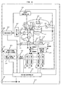
- FIG. 2 is a block diagram showing an information storage apparatus.
- the information storage apparatus with a recording medium 100 mounted thereon is shown.
- the recording medium 100 is essential.
- the recording medium 100 is removed from or mounted on the information storage apparatus as required.
- a chucking mechanism 112 for holding the recording medium 100 is mounted on the rotary shaft 111 of a motor 110 mounted on a box 108.
- the chucking mechanism 112 thus constitutes a holding mechanism of the recording medium 100.
- the motor 110, the rotary shaft 111 and the chucking mechanism 112 make up a moving mechanism for moving the recording medium 100 and the energy beam relatively to each other.
- a rail 115 is mounted on the box 108.
- a pair of rail guides 116 guided by a rail 114 are mounted on the case 117.
- a linear gear 119 is mounted on the case 117, and a rotary gear 120 is mounted on the linear gear 119.
- the turning effort of the rotary motor 118 mounted on the box 108 is transmitted to the rotary gear 120 so that the case 117 linearly moves along the rail 115.
- the direction of this linear motion is substantially along the radius of the recording medium 100.
- a magnet 121 is mounted on the case 117.
- An objective lens 136 is mounted also on the case 117 through a suspension 123 adapted to move the objective lens 136 only in two directions, i.e. substantially along the normal to the recording surface of the recording medium 100 and substantially radially of the recording medium 100.
- a coil 122 in substantially opposed relation to the magnet 121 is mounted on the objective lens 136. By supplying a current to the coil 122 and thus producing a magnetic effect, the objective lens 136 can be moved in two directions, i.e. substantially along the normal to the recording surface of the recording medium 100 and substantially radially of the recording medium 100.
- the rail 115, the rail guides 116, the case 117, the magnet 121, the suspension 123, the coil 122 and the objective lens 136 make up a positioning mechanism for setting the energy beam in position on the recording medium 100.
- a semiconductor laser 131 constituting an energy beam generator is mounted on the case 117.
- the energy beam emitted from the semiconductor laser 131 is passed through a collimate lens 132, a beam splitter 133 and then through the objective lens 136.
- the light emitted from the objective lens 136 is partially reflected from the recording medium 100, passes through the objective lens 136, reflected from the beam splitter 133, and focused by a detection lens 134 so that the light intensity thereof is detected by a photo detector 135.
- the photo detector 135 has a light-receiving area segmented into a plurality of areas.
- the light intensity detected in each light-receiving area is amplified by an amplifier 152 while being arithmetically processed, thereby detecting the information (servo signal) on the relative positions of the light spot focused by the objective lens 136 and the recording medium 100 and an information read signal.
- the servo signal is sent to a servo controller 151, and the read signal is sent to a decoder 153.
- the detector 140 is activated and applies the output signal thereof to a system controller 150.
- the system controller 150 controls the motor 110 thereby to rotate the recording medium 100 at an appropriate rpm.
- the system controller 150 controls the rotary motor 118 and thus sets the case 117 in position.
- the system controller 150 causes the semiconductor laser 131 to emit light, while at the same time activating the servo controller 151.
- the rotary motor 118 is started so that the current is supplied to the coil 123 and the focus spot formed by the objective lens 136 is set in position on the recording medium 100.
- the servo controller 151 sends a signal to the system controller 150 indicating that the focus spot is formed on the recording medium 100.
- the system controller 150 instructs a decoder 153 to decode the signal read out.
- the system controller 150 gives an instruction to the servo controller 151 to set the focus spot in position on the information track of the control data zone.
- the system controller 150 reads the information track of the control data zone and reads the medium information for the recording operation.
- the parameters for the recording strategy described with reference to Fig. 1 are written in the information track of the control data zone. Such information as the recording power level, the temporal relation between the recording pulses and the look-up table are read by the system controller 150 from the recording medium 100. These parameters of the recording strategy are written by the system controller 150 in the parameter table of the signal processing circuit 154, the parameter table of the delay circuit 155 and the current sink amount parameter of the current sinks 156.
- the system controller 150 instructs the servo controller 151 to set the focus spot in position on the recording medium 100.
- the signal produced from the photo detector 135 is decoded by the decoder 153, and then the information read is sent to the host controller through an output connector 158.
- the system controller 150 gives an instruction to the servo controller 151 to set the focus spot in position on the recording medium 100.
- the information to be written is converted into an NRZI signal through the signal processing circuit 161.
- the signal thus converted into the NRZI signal is converted into a plurality of appropriate pulse chains through the signal processing circuit 154. These pulse chains are transmitted through the delay circuit 155 to the current sinks 156.
- the signal processing circuit 161 and the signal processing circuit 154 constitute a circuit for converting the information to be written, into a recording pulse chain.
- the semiconductor laser 131 is connected to a constant-current source 157 to maintain a constant value of the total current consumed in the semiconductor laser 131 and the current sinks 156.
- the constant-current source 157 is connected with a plurality of the current sinks 156. Whether the current sinks 156 operate and absorb the current or not depends on the signal generated in the signal processing circuit 154 and passed through the delay circuit 155. Upon activation of the current sinks 156, the current produced from the constant-current source 157 is partially absorbed into the current sinks 156, with the result that the amount of the current flowing into the semiconductor laser 131 is reduced, thereby changing the energy level of the energy beam generated from the semiconductor laser 131.
- the signal processing circuit 154 and the delay circuit 155 activate a plurality of the current sinks 156 at an appropriate timing and thus realize the recording strategy shown in Fig. 1.
- the information recording apparatus is supplied with power from an external source through a terminal 160.
Abstract
Description
- The present invention relates to a method of and an apparatus for recording information using an information recording medium capable of recording information by radiation of an energy beam, or in particular to a method of recording information high in compatibility and accuracy.
- A DVD-RAM for realizing a memory capacity of 2.6 GB on one side of a disk 120 mm in diameter using a phase-change material finds practical applications. In forming a recording mark on this disk, the power of an energy beam is changed between high and low levels while the portions (space portions) of the medium between recording marks are irradiated with an energy beam of a predetermined different power level. Specifically, a multi-pulse energy beam is radiated for forming a recording mark and includes (except for short recording marks) four types of pulses, i.e. a first pulse, a multi-pulse chain (middle pulse chain), a last pulse and a negative pulse following the last pulse. This recording method has the advantage that what is called the overwriting (rewriting by overwriting) is possible in which new information is recorded while erasing the existing information. The power level of the energy beam is recorded beforehand in the control data of the recording medium, and the actual radiation power of the energy beam is determined based on this information.
- In the prior art described above, the energy amount contained in the middle pulse chain depends on not only the high and low power levels of the middle pulse chain but also the duty factor of the middle pulse chain. Therefore, the energy amount contained in the middle pulse chain cannot be fully controlled simply by setting the high and lower power levels of the middle pulse chain to a predetermined value. For this reason, a recording mark is not necessarily formed to the correct shape by the middle pulse chain, often deteriorating the compatibility of recording. Especially in the case where information is recorded with high density in a 4.7 GB DVD-RAM, an insufficient energy amount in the middle portion of the recording mark under unstable control forms a recording mark with a thin middle portion, or an insufficient magnitude of the rear portion of the recording mark, thereby causing an unrequired edge shift in the reproduction signal and thus an insufficient compatibility for recording and reproduction. An excessively large energy amount resulting from an unstable control of the middle portion of the recording mark, on the other hand, forms a recording mark with a thick middle portion or with an excessively large rear portion, and generates an unrequired edge shift in the reproduction signal, thereby leading to the problem of an insufficient compatibility for recording and reproduction.
- According to one aspect of the invention, there is provided a method of recording information for forming each recording mark in a recording medium by radiating a pulse chain of an energy beam including a first pulse, a middle pulse chain, a last pulse and a negative pulse following the last pulse.
- Said method can comprise a step of recording the designated values of the power level of the first pulse, the upper and lower power levels of the middle pulse chain, the power level of the last pulse and the power level of the negative pulse in a control data zone of the recording medium in advance.
- Furthermore, said method can comprise a step of adjusting the average power of the first pulse to the designated power level value of the first pulse in the control data zone;
- furthermore, said method can comprise a step of adjusting the average power of the middle pulse chain to the arithmetic mean of the designated upper power level value and the designated lower power level value in the control data zone;
- furthermore, said method can comprise a step of adjusting the average power of the last pulse to the designated power level of the last pulse in the control data zone;
- furthermore, said method can comprise a step of adjusting the average power of the negative pulse to the designated power level of the negative pulse in the control data zone; and
- furthermore, said method can comprise a step of adjusting the variation of the power level of the energy beam of the middle pulse chain to the difference between the designated upper power level and the designated lower power level in the control data zone.
-
- According to another aspect of the invention, there can be provided an apparatus for controlling the ratio of the average power between the first pulse, the middle pulse chain and/or the last pulse to a predetermined value.
-
- Fig. 1 is a diagram showing an example of time-sequential change of the power level of the energy beam radiated on a recording medium when information is recorded in the medium.
- Fig. 2 is a diagram showing a configuration of an information recording apparatus.
-
- First, an example of time-sequential change of the power level of the energy beam radiated on a recording medium for recording information therein will be explained with reference to Fig. 1. The manner in which the power level is changed in time-sequential fashion when recording information will be generally called a write strategy or a recording strategy. Take a DVD-RAM as an example. In the case of DVD-RAM, the shortest mark or the shortest space has a length of 3T (three times as long as the time T), where T is the time width of the reference clock for recording and reproduction. Normally, the longest mark or space has a length of 11T, although a special pattern has a length of 14T.
- A NRZI signal constituting information to be recorded chronologically on a recording medium, when supplied, is converted into a temporal change of the power level of the energy beam by an appropriate signal processing circuit. This temporal change of the power level is indicated as an optical pulse waveform in Fig. 1. The power is set to four levels including the peak power, the
bias power 1, thebias power 2 and thebias power 3. The recording medium can be transferred to a first state inbias power 1, and to a second state in peak power. Thebias power 3 is a level equal to or lower than thebias power 1. When forming an area of second state 4T or longer (i.e. with the NRZI signal 4T or longer) in the recording medium, a period ofbias power 3 in power level is mixed in the radiation period of the peak power thereby to multi-pulsate the energy beam. Of the multi-pulsated energy beam, the first light pulse is called the first pulse and the last light pulse the last pulse. Between the first and last pulses, the light pulse alternating between peak power andbias power 3 is repeated in accordance with the length of the NRZI signal. The number of alternations, i.e. repetitions is given as (n - 4) where n is the length of the NRZI signal and larger than 3. The whole repetitive pulses interposed between the first and last pulses are called the middle pulse chain. Also, a negative pulse holding the power level ofbias power 2 is radiated following the last pulse. Thebias power 2 is set to a level equal to or lower than thebias power 1. Thus, when forming an area in second state corresponding to the NRZI signal having a length of 5T or more, the recording pulses include the first pulse, the middle pulses, the last and the negative pulse. When forming an area in second state corresponding to the NRZI signal having a length of 4T or more, on the other hand, the recording pulses include the first pulse, the last and the negative pulse. Also, when forming an area in second state corresponding to the NRZI signal having a length of 3T, the recording pulse includes a single light pulse (first pulse or a single pulse) and the negative pulse. - The reference values of the peak power,
bias power 1,bias power 2 andbias power 3 may be recorded in advance at an appropriate place in the recording medium as medium information. The portion of the recording medium where the medium information on the recording strategy is called the information track of the control data zone. The reference value of the power level is read from the information track of the control data zone of the recording medium, and with reference to the particular reference value, each power level is determined for the write operation. The designated value of the power level of the first pulse is the peak power, the designated value of the upper power level of the middle pulse chain is the peak power while the designated value of the lower power level thereof is thebias power 3, the designated value of the power level of the last pulse is the peak power, and the designated value of the power level of the negative pulse is thebias power 2. The temporal designated value of these pulses may be also recorded in the information track. - First, consider the case in which an area in second state corresponding to the NRZI signal having a length of at least 4T is formed in a recording medium, and let us define the recording waveform. The leading edge of the first pulse in the write pulse chain is defined at the time point following the lapse of time TSFP from the leading edge of the NRZI signal, and the trailing edge of the first pulse in the write pulse chain is defined at the time point following the lapse of time TEFP from the leading edge of the NRZI signal. The length of the first pulse is TFP which is equal to the difference between TEFP and TSFP. The leading edge of the last pulse in the write pulse chain occurs at the time point following the lapse of time TSLP from the reference time point earlier by 2T from the trailing edge of the NRZI signal. The trailing edge of the last pulse in the write pulse chain, on the other hand, occurs at the time point following the lapse of time TELP from the reference time point earlier by 2T from the trailing edge of the NRZI signal. The length of the last pulse is TLP and is equal to the difference between TELP and TSLP.
- There may exist a middle pulse chain between the first pulse and the last pulse. The leading edge of each pulse in the middle pulse chain coincides with the reference clock position, and the trailing edge of each pulse occurs at the time point following the lapse of time TMP from the trailing edge of each pulse.
- Now, consider the case in which an area in second state corresponding to the NRZI signal of 3T is formed in a recording medium. The leading edge of the light pulse occurs at the time point following the lapse of TSFP from the leading edge of the NRZI signal. The trailing edge of the light pulse, on the other hand, occurs at the time point following the lapse of time TELP from the reference time point earlier by 2T from the trailing edge of the NRZI signal.
- There is a portion having a power level of
bias power 2 following the last pulse of the recording pulse chain 4T or longer or following the recording pulse of 3T, which portion has a length of TLC. - The reference values of the time points TSFP, TEFP, TFP, TSLP, TELP, TLP, TLC and TMP for defining the recording pulses are read from the information track of the control data zone of the recording medium, and by reference to these reference values, the values of these time points are determined.
- The time points TSFP, TEFP, TFP, TSLP, TELP, TLP, TLC and TMP for defining the recording pulses do not always assume a predetermined value, but may be required to be changed in accordance with the combination of the NRZI signals. Consider the case of a DVD-RAM having a capacity of 4.7 GB on one side in particular. The shortest mark of 3T has a length of about 0.42 microns which is shorter than the write spot radius of 0.45 microns. In this high-density recording operation, the thermal interference between adjoining marks increases to such an extent that it is difficult to assure an always stable recording operation. An idea conceived to overcome this inconvenience is to change the recording waveform adaptively in accordance with the combination of the portions before and after the NRZI signal. The following two methods are available for correcting the shift of the front edge.
- 1) To change TSFP while fixing TEFP. In the process, TFP changes with TSFP.
- 2) To change TSFP while fixing TFP. In the process, TEFP changes with TSFP.
-
- On the other hand, the following two methods are employed for correcting the shift of the rear edge.
- 1) To change TELP while fixing TSLP. In the process, TLP changes with TELP.
- 2) To change TELP while fixing TLP. In the process, TSLP changes with TELP.
-
- Which of the above-mentioned methods is selected for controlling the front edge and the rear edge depends on the manner in which the recording medium is designed and the recording characteristics of the recording medium. Which method is to be selected for controlling the shift of the front edge or the rear edge is best understood by the manufacturer of the recording medium, and therefore such a manufacturer can recommend to the information recording apparatus as to which method should be selected for controlling the edge shift. Specifically, the manufacturer of the recording medium writes a recommendation of an edge shift control method at a specified place on the recording medium. This information is read by the information recording apparatus thereby to determine a method of controlling the edge shift. In such a case, the medium characteristics intended for by the recording medium manufacturer can be fully utilized by the information recording apparatus, and therefore a most stable information recording is made possible. Also, the recording medium manufacturer prepares a look-up table for edge shift control and records it in the recording medium. This look-up table is read by the information recording apparatus, and by referring to it, the edge shift is controlled. In this way, all the medium characteristics intended for by the recording medium manufacturer can be utilized by the information recording apparatus, and thus a most stable information recording is made possible. These ideas can provide means for securing the best compatibility of the recording with high recording density.
- Let M(n) be the length of a mark to be recorded, and S(n-1) be the length of the space leading the mark. The look-up table for the front edge is a series of values determined by the combinations of M(n) and S(n-1) which values can be either positive or negative.
- Let M(n) be the length of a mark to be recorded, and S(n+1) be the length of the space following the mark. The look-up table for the rear edge is a series of values determined by the combinations of M(n) and S(n+1) which values can be either positive or negative.
- As described above, the mark edge position can be controlled always accurately by changing TSFP and TELP in accordance with the combinations of the portions before and after the NRZI signal.
- The compatibility of the recording of the information using the aforementioned recording strategy will be discussed below.
- Assume that the recording compatibility is defined as the fact that a stable write operation can be performed with a similar write strategy between different apparatuses and the recording marks written by the apparatuses can be read as a reproduction signal having a similar characteristic. With a writable optical disk apparatus, it is essential to have a recording compatibility, as well as a reproduction compatibility, to realize the interchangeability of the information medium. This in turn requires the following conditions.
- 1) The recording waveform has no excessive overshoot or undershoot.
- 2) The energy amount contained in each of the first pulse, the middle pulses, the last pulse and the negative pulse (or an average power level of the pulses, which is given as the energy contained in a pulse divided by the pulse holding time) is controlled to a predetermined value.
- 3) The energy beam for holding the power level
of
bias power 1 is supplied in stable manner and the value ofbias power 1 is controlled to a predetermined value, or the average power is controlled to a predetermined value during the period when the level ofbias power 1 is held. -
- In a phase-change medium like the DVD-RAM, the condition (2) above is especially important for securing the recording compatibility. Specifically, the first pulse has the function of starting the melting of the recording film by radiating a large average power on the recording medium, and the middle pulses have the function of continuing the melting of the recording film with a comparatively low average power. On the other hand, the last pulse applies a rather large average power to secure a stable shape of the rear portion of the recording mark, while the negative pulse of a small average power following the last pulse is used to stabilize the shape of the rear portion of the recording mark. In this way, the recording pulses including the first pulse, the middle pulses, the last pulse and the pulse for holding the level of
bias power 3 have different functions, and therefore the values thereof or the ratio of the values thereof are required to be accurately controlled. - In an actual recording apparatus, the radiation energy amount of the energy beam is varied with the temperature changes or the like. First of all, therefore, the ratio of average power is controlled between the first pulse, middle pulses, the last pulse and the negative pulse, and then while holding the ratio, the whole power level is changed to determine an optimum power. By doing so, it is always possible to accurately determine the recording pulse capable of realizing a recording mechanism suitable for the recording medium. To the extent that the radiation energy amount remains unchanged, however, the average power of each of the first pulse, the middle pulse chain, the last pulse and the negative pulse can be controlled.
- The recording compatibility can be substantially secured if the average power of each pulse as described in (2) above is controlled to about ±5% in terms of an error from a value to be set. As long as the average power is controlled this way, the overshoot or undershoot described in (1) above is allowable to about ±10% of the power level to be set or to about ± 10% of the power level change. The recording pulses are a pulse chain very high in speed, and therefore an overshoot or an undershoot is liable to occur. As far as the condition (2) above is met, however, a large allowance of (1) above can be given and thus the apparatus design is facilitated. This makes it possible to realize a recording apparatus having a stable performance and to perform the recording/reproduction in stable fashion with a high compatibility. As for the condition (3) above, on the other hand, the
bias power 1 is a quasi-DC level existing between a given multi-pulse chain and the following multi-pulse chain, and it is not very difficult to hold the accuracy of thebias power 1 at the accuracy of about ±5%. - Even when the average power of the middle pulse chain is set to a predetermined value, the width of change of the power level of the middle pulse chain is not always secured due to the overshoot or undershoot. For a phase-change recording medium such as the DVD-RAM, even if the average power of the middle pulse chain is set to a predetermined value, the middle portion of the recording mark cannot be formed with a sufficient accuracy in the case where the change width of the power level is excessively large or excessively small. The designated value of the change width of the power level of the middle pulse chain is the difference between the designated peak power value and the designated value of
bias power 3. In the actual recording waveform, however, an error of up to about ± 20% from the designated value is allowed for the change width of the power level of the middle pulse chain. As a result, once the average power of the middle pulse chain is adjusted to the accuracy of ±5% from the designated value, an error of up to about 10% from the designated value can be allowed for the upper power and the lower power, respectively, of the middle pulse chain. - A sufficient recording compatibility can be maintained by setting the following target values of the average power of the respective pulses. Specifically, the average power level of the first pulse is set to the designated peak power value ± 5%, the average power level of the middle pulse chain is set to the designated middle power level ± 5% when the designated middle power is defined as 0.5 x (designated peak power value + designated value of bias power 3), the average power level of the last pulse is set to the designated peak power value ± 5%, and the average power level of the negative pulse is set to the designated value of
bias power 2 ± 5%. The designated values of the peak power,bias power 1,bias power 2 andbias power 3 may be recorded in the control data of the recording medium, in which case they can be read and used. - Even when adjusting the ratio of each pulse in advance, the power of each pulse is set as described above first of all. Then, the power of each pulse is changed in such a manner as not to change the ratio of average power between these pulses, and thus the optimum power is determined.
- From the temporal change of the power actually radiated on the recording medium, the following method is proposed as one of the methods of determining the average power level of the first pulse. Specifically, assume that the line representing X% of the power level to be set is crossed first upward by the level of the first pulse at the
time point 1 and the line representing X% of the power level to be set is first crossed downward by the level of the first pulse at thetime point 2. The power levels of these two time points are integrated with each other, and the result is divided by the integration time to obtain the average power of the first pulse. In this method, X% may be 90%, 95% or otherwise can be set according to the conditions of the apparatus. - From the temporal change of the power actually radiated on the recording medium, on the other hand, the following method is proposed as one of the methods of determining the average power level of the middle pulses. In view of the fact that the middle pulses are generated only in a recording mark not less than 5T in length, the description below is limited to the recording mark not less than 5T in length. Assuming that the length of the NRZI signal is nT (n > 4), consider the time-sequential change for (n-4)T. Consider two time points,
time point 1 andtime point 2 distant from each other by two time-sequential changes. These time points are set in such a manner as to contain all the middle pulses between them. The power level between the two time points is integrated, and the result is divided by the integration time thereby to determine the average power level of the middle pulses. - From the temporal change of the power actually radiated on the recording medium, the following method is proposed as one of the methods of determining the average power level of the last pulse. Specifically, assume that the line representing Y% of the power level to be set is crossed first upward by the level of the last pulse at the
time point 1 and the line representing Y% of the power level to be set is last crossed downward by the level of the last pulse at thetime point 2. The power level between these two time points is integrated and the result is divided by the integration time to obtain the average power of the last pulse. In this method, Y% may be 90%, 95% or otherwise can be set according to the conditions of the apparatus. - From the temporal change of the power actually radiated on the recording medium, the following method is proposed as one of the methods of determining the average power level of the negative pulse. Specifically, assume that the line representing Z% of the power level to be set is crossed first downward by the level of the negative pulse at the
time point 1 and the line representing Z% of the power level to be set is last crossed upward by the level of the negative pulse at thetime point 2. The power level between these two time points is integrated and the result is divided by the integration time to obtain the average power level of the negative pulse. In this method, Z% may be 110%, 105% or otherwise can be set according to the conditions of the apparatus. In the case where thebias power 2 and thebias power 1 are at the same level or have only a small difference, however, thetime point 2 may be difficult to define. In such a case, thetime point 2 is regarded as the time point following the lapse of the time required to hold thebias power level 2 from thetime point 1. Then, the power level between thetime points - From the temporal change of the power actually radiated on the recording medium, the following method is proposed as one of the methods of determining the average power level of the
bias power 1. specifically, assume that thetime point 2 is the one used for determining the average power level of the negative pulse and thetime point 3 is the one at which the line representing W% of the power level to be set is last crossed upward by the level of thebias power 1. The power level between these twotime points bias power 1. In this method, W% may be 110%, 105% or otherwise can be determined according to the conditions of the apparatus. However, the holding time of thebias power 1 is so long that if the power is determined from the average power, the comparatively slow power change adversely affecting the erase characteristic cannot be suppressed. It is therefore necessary to take care to reduce such a power change. - Another embodiment of the invention will be explained with reference to Fig. 2. Fig. 2 is a block diagram showing an information storage apparatus. By way of explanation, the information storage apparatus with a recording medium 100 mounted thereon is shown. For storing information, the recording medium 100 is essential. The recording medium 100, however, is removed from or mounted on the information storage apparatus as required.
- In Fig. 2, a
chucking mechanism 112 for holding the recording medium 100 is mounted on therotary shaft 111 of amotor 110 mounted on abox 108. Thechucking mechanism 112 thus constitutes a holding mechanism of the recording medium 100. Also, themotor 110, therotary shaft 111 and thechucking mechanism 112 make up a moving mechanism for moving the recording medium 100 and the energy beam relatively to each other. - A
rail 115 is mounted on thebox 108. A pair of rail guides 116 guided by a rail 114 are mounted on thecase 117. Also, a linear gear 119 is mounted on thecase 117, and a rotary gear 120 is mounted on the linear gear 119. The turning effort of the rotary motor 118 mounted on thebox 108 is transmitted to the rotary gear 120 so that thecase 117 linearly moves along therail 115. The direction of this linear motion is substantially along the radius of the recording medium 100. - A
magnet 121 is mounted on thecase 117. Anobjective lens 136 is mounted also on thecase 117 through asuspension 123 adapted to move theobjective lens 136 only in two directions, i.e. substantially along the normal to the recording surface of the recording medium 100 and substantially radially of the recording medium 100. Also, acoil 122 in substantially opposed relation to themagnet 121 is mounted on theobjective lens 136. By supplying a current to thecoil 122 and thus producing a magnetic effect, theobjective lens 136 can be moved in two directions, i.e. substantially along the normal to the recording surface of the recording medium 100 and substantially radially of the recording medium 100. Therail 115, the rail guides 116, thecase 117, themagnet 121, thesuspension 123, thecoil 122 and theobjective lens 136 make up a positioning mechanism for setting the energy beam in position on the recording medium 100. - A
semiconductor laser 131 constituting an energy beam generator is mounted on thecase 117. The energy beam emitted from thesemiconductor laser 131 is passed through acollimate lens 132, abeam splitter 133 and then through theobjective lens 136. The light emitted from theobjective lens 136 is partially reflected from the recording medium 100, passes through theobjective lens 136, reflected from thebeam splitter 133, and focused by adetection lens 134 so that the light intensity thereof is detected by aphoto detector 135. Thephoto detector 135 has a light-receiving area segmented into a plurality of areas. The light intensity detected in each light-receiving area is amplified by anamplifier 152 while being arithmetically processed, thereby detecting the information (servo signal) on the relative positions of the light spot focused by theobjective lens 136 and the recording medium 100 and an information read signal. The servo signal is sent to aservo controller 151, and the read signal is sent to adecoder 153. - Once the recording medium 100 is mounted on the information storage apparatus and the
chucking mechanism 112 is fixed on the recording medium 100, thedetector 140 is activated and applies the output signal thereof to asystem controller 150. Upon receipt of the signal, thesystem controller 150 controls themotor 110 thereby to rotate the recording medium 100 at an appropriate rpm. Also, thesystem controller 150 controls the rotary motor 118 and thus sets thecase 117 in position. Further, thesystem controller 150 causes thesemiconductor laser 131 to emit light, while at the same time activating theservo controller 151. Thus, the rotary motor 118 is started so that the current is supplied to thecoil 123 and the focus spot formed by theobjective lens 136 is set in position on the recording medium 100. Then, theservo controller 151 sends a signal to thesystem controller 150 indicating that the focus spot is formed on the recording medium 100. Thesystem controller 150 instructs adecoder 153 to decode the signal read out. In the case where the track read out is not the information track in the control data zone, thesystem controller 150 gives an instruction to theservo controller 151 to set the focus spot in position on the information track of the control data zone. As the result of this operation, thesystem controller 150 reads the information track of the control data zone and reads the medium information for the recording operation. - The parameters for the recording strategy described with reference to Fig. 1 are written in the information track of the control data zone. Such information as the recording power level, the temporal relation between the recording pulses and the look-up table are read by the
system controller 150 from the recording medium 100. These parameters of the recording strategy are written by thesystem controller 150 in the parameter table of thesignal processing circuit 154, the parameter table of thedelay circuit 155 and the current sink amount parameter of the current sinks 156. - In the case where an instruction for information reproduction is sent from a host controller through an
input connector 159, thesystem controller 150 instructs theservo controller 151 to set the focus spot in position on the recording medium 100. Thus, the signal produced from thephoto detector 135 is decoded by thedecoder 153, and then the information read is sent to the host controller through anoutput connector 158. - In the case where an instruction to write information and the information to be written are sent from the host controller through the
input connector 159, thesystem controller 150 gives an instruction to theservo controller 151 to set the focus spot in position on the recording medium 100. Also, the information to be written is converted into an NRZI signal through the signal processing circuit 161. The signal thus converted into the NRZI signal is converted into a plurality of appropriate pulse chains through thesignal processing circuit 154. These pulse chains are transmitted through thedelay circuit 155 to the current sinks 156. The signal processing circuit 161 and thesignal processing circuit 154 constitute a circuit for converting the information to be written, into a recording pulse chain. - The
semiconductor laser 131 is connected to a constant-current source 157 to maintain a constant value of the total current consumed in thesemiconductor laser 131 and the current sinks 156. The constant-current source 157 is connected with a plurality of the current sinks 156. Whether thecurrent sinks 156 operate and absorb the current or not depends on the signal generated in thesignal processing circuit 154 and passed through thedelay circuit 155. Upon activation of thecurrent sinks 156, the current produced from the constant-current source 157 is partially absorbed into thecurrent sinks 156, with the result that the amount of the current flowing into thesemiconductor laser 131 is reduced, thereby changing the energy level of the energy beam generated from thesemiconductor laser 131. - The
signal processing circuit 154 and thedelay circuit 155 activate a plurality of thecurrent sinks 156 at an appropriate timing and thus realize the recording strategy shown in Fig. 1. - For performing the aforementioned operation, the information recording apparatus is supplied with power from an external source through a terminal 160.
- In the information recording apparatus described above, there are two methods for realizing the information recording method described with reference to Fig. 1.
- 1) The power of the energy beam emitted from the objective lens is measured by power meter thereby to measure the average power level of the first pulse, the middle pulse chain, the last pulse and the negative pulse. The power of the energy beam emitted from the objective lens can be measured by a power meter installed immediately after the objective lens or by detecting part of the light emitted from the energy beam generator. The designated values for the current sinks and the delay circuit are adjusted so that the measurement of the average energy of each pulse coincides with the corresponding designated value or each measurement is a (a: real number) times as large as the corresponding designated value. In the case where each measurement is set to a value a (a: real number) times as large as the corresponding designated value, the information is recorded in the recording medium while changing the value of a and reproduced from the recording medium. Then, the value of a is adjusted to minimize the error information detected by the decoder. Assuming that the value of a is finally determined as a1, the optimum power level of the recording pulse is a1 times the designated value. The system controller has stored therein the procedure for controlling the sequence mentioned above.
- 2) For the information recording apparatus lacking the function of directly measuring the average power of each pulse, the information recording method described with reference to Fig. 1 is realized in substantial manner. Specifically, a mass-produced information recording apparatus simple in construction has considerable variations in power accuracy and temporal accuracy of the recording pulse. In order to suppress these variations, the power is adjusted mutually between the first pulse, the last pulse and the negative pulse. For the middle pulse chain, on the other hand, the power is adjusted while at the same time adjusting the average power by regulation of the duty factor. As a result, it is possible to produce a superior recording waveform with the power balanced between the first pulse, the middle pulse chain, the last pulse and the negative pulse. Also, while maintaining a predetermined ratio of power between these pulses, the power level of each pulse is adjusted and the optimum power value is determined, so that an optimum recording power always suited to the recording medium can be obtained. The system controller has stored therein the procedure for controlling this sequence.
-
- It will thus be understood from the foregoing description of the embodiment that according to the present invention, an always stable recording compatibility can be secured, and the limitation on the overshoot and the undershoot of the recording waveform can be relaxed. This facilitates the design of the recording apparatus, resulting in a high reliability and compatibility of the recording apparatus.
Claims (4)
- A method of recording information for forming each recording mark in a recording medium (100) by radiating a pulse chain of an energy beam including a first pulse, a middle pulse chain, a last pulse and a negative pulse following the last pulse, comprising the steps of:recording the designated values of the power level of said first pulse, the upper power level and the lower power level of said middle pulse chain, the power level of said last pulse and the power level of said negative pulse in the control data zone of said recording medium in advance;adjusting the average power of the first pulse to the designated power level of the first pulse recorded in the control data zone;adjusting the average power of the middle pulse chain to the arithmetic mean of the designated upper power level and the designated lower power level recorded in the control data zone;adjusting the average power of the last pulse to the designated power level of the last pulse recorded in the control data zone;adjusting the average power of the negative pulse to the designated power level of the negative pulse recorded in the control data zone; andadjusting the variation of the power level of the energy beam of the middle pulse chain to the difference between the designated upper power level and the designated lower power level recorded in the control data zone.
- A method of recording information for forming each recording mark in a recording medium (100) by radiating a pulse chain of an energy beam including a first pulse, a middle pulse chain, a last pulse and a negative pulse following the last pulse, comprising the steps of:recording the designated values of the power level of the first pulse, the upper power level and the lower power level of the middle pulse chain, the power level of the last pulse and the power level of the negative pulse in the control data zone of the recording medium in advance;adjusting the average power of said first pulse to the product of the designated pulse level value of the first pulse recorded in the control data zone and the value a, where a is a real number;adjusting the average power of said middle pulse chain to the product of the value a and the arithmetic mean of the upper designated power level value and the lower designated power level value recorded in said control data zone;adjusting the average power of said last pulse to the product of the designated power level value of the last pulse recorded in said control data zone and the value a;adjusting the average power of said negative pulse to the product of the designated power level value of the negative pulse recorded in said control data zone and the value a;adjusting the change width of the power level of the energy beam of said middle pulse train to the product of the value a and the difference between the upper designated power level value and the lower designated power level value recorded in said control data zone; andmeasuring the recording characteristic and the recording/reproduction characteristic while changing the value a after adjusting the power of each of said pulse using the arbitrary value of a, and determining the value of a associated with the best recording characteristic and the best recording/reproduction characteristic thereby to determine the optimum recording power for said recording medium.
- An information recording apparatus comprising an energy beam generator (131), a power adjusting mechanism (150, 155-157) capable of adjusting the power level of the energy beam generated by said energy beam generator, a holding mechanism (112) capable of holding said recording medium, a moving mechanism (111, 112, 115, 116, 118-122) capable of moving said energy beam and said recording medium relatively to each other, and a signal processing circuit (150, 154, 161) for converting the information to be recorded to the power level of said energy beam;
wherein said recording medium is irradiated with a pulse chain of the energy beam including a first pulse, a middle pulse chain following said first pulse, a last pulse following said middle pulse train, and a negative pulse following said last pulse when forming each recording mark on the recording medium, thereby determining the optimum energy beam power for recording the information in said recording medium using the information recording method according to Claim 1 or 2. - An information recording apparatus for forming a recording mark by radiating an energy beam on a recording medium (100) mounted separately, comprising:means (131) for radiating the energy beam for forming one recording mark on said recording medium; andcontrol means (150, 110-112, 115, 116, 118-122, 154, 161) for controlling a multi-pulse chain indicating the radiation timing of said energy beam in such a manner as to secure a predetermined ratio of the average power between said first pulse, said last pulse and the middle pulse chain excluding the first pulse and the last pulse.
Applications Claiming Priority (2)
| Application Number | Priority Date | Filing Date | Title |
|---|---|---|---|
| JP10488399A JP3762847B2 (en) | 1999-04-13 | 1999-04-13 | Information recording method and information recording apparatus |
| JP10488399 | 1999-04-13 |
Publications (2)
| Publication Number | Publication Date |
|---|---|
| EP1045378A2 true EP1045378A2 (en) | 2000-10-18 |
| EP1045378A3 EP1045378A3 (en) | 2002-02-13 |
Family
ID=14392594
Family Applications (1)
| Application Number | Title | Priority Date | Filing Date |
|---|---|---|---|
| EP00107071A Ceased EP1045378A3 (en) | 1999-04-13 | 2000-04-05 | Method of and apparatus for recording information |
Country Status (7)
| Country | Link |
|---|---|
| US (3) | US6678228B1 (en) |
| EP (1) | EP1045378A3 (en) |
| JP (1) | JP3762847B2 (en) |
| KR (1) | KR100533557B1 (en) |
| CN (2) | CN1129895C (en) |
| SG (1) | SG97882A1 (en) |
| TW (1) | TW509935B (en) |
Cited By (6)
| Publication number | Priority date | Publication date | Assignee | Title |
|---|---|---|---|---|
| EP1233411A2 (en) * | 2001-02-19 | 2002-08-21 | Samsung Electronics Co., Ltd. | Optical recording pulse generating apparatus and method for generating optical recording pulse |
| EP1248253A2 (en) * | 2001-04-06 | 2002-10-09 | Ricoh Company | Optical information recording medium and information recording method and apparatus using the recording medium |
| EP1300836A2 (en) * | 2001-10-02 | 2003-04-09 | Matsushita Electric Industrial Co., Ltd. | Optical information recording method, optical information recording and reproducing device, and optical information recording medium |
| EP1484753A2 (en) * | 2003-06-02 | 2004-12-08 | Ricoh Company, Ltd. | Information recording apparatus, information recording method, and information recording system |
| US7167431B2 (en) * | 2002-02-14 | 2007-01-23 | Tdk Corporation | Method for recording information on optical recording medium, information recorder, and optical recording medium |
| WO2007105139A1 (en) * | 2006-03-13 | 2007-09-20 | Koninklijke Philips Electronics N. V. | Real time power control for optical recording drives |
Families Citing this family (28)
| Publication number | Priority date | Publication date | Assignee | Title |
|---|---|---|---|---|
| JP3762847B2 (en) * | 1999-04-13 | 2006-04-05 | 株式会社日立製作所 | Information recording method and information recording apparatus |
| KR100326338B1 (en) * | 1999-09-18 | 2002-03-08 | 구자홍 | Method for recording the data on a optical disc using optimal power |
| TW518580B (en) * | 2000-05-11 | 2003-01-21 | Koninkl Philips Electronics Nv | Methods and devices for recording marks on a recording surface of an optical record carrier |
| US7366074B2 (en) * | 2000-05-11 | 2008-04-29 | Koninklijke Philips Electronics N. V. | Methods and devices for recording marks on a recording surface of an optical record carrier |
| JP2002100044A (en) * | 2000-09-25 | 2002-04-05 | Sony Corp | Optical recording device and laser power control method thereof |
| KR100403614B1 (en) * | 2000-11-29 | 2003-11-01 | 삼성전자주식회사 | Adaptive recording Control method for high dencity optical recording |
| JP2002358640A (en) * | 2001-05-28 | 2002-12-13 | Sony Corp | Optical recorder and laser power control method |
| JP2002358641A (en) | 2001-05-28 | 2002-12-13 | Sony Corp | Optical recorder and laser power control method |
| EP1421580A1 (en) * | 2001-08-24 | 2004-05-26 | Koninklijke Philips Electronics N.V. | Optical record carrier recording method and apparatus |
| JP2003208713A (en) * | 2002-01-16 | 2003-07-25 | Tdk Corp | Information recording method on optical recording medium, optical recording medium, and information recording/reproducing apparatus |
| US7376064B2 (en) * | 2002-02-25 | 2008-05-20 | Samsung Electronics Co., Ltd. | Method and apparatus for recording data on optical recording medium |
| JP2003317395A (en) * | 2002-04-15 | 2003-11-07 | Pioneer Electronic Corp | Information recording device and information recording method |
| US7492682B2 (en) * | 2002-07-25 | 2009-02-17 | Yamaha Corporation | Optical disk recording apparatus controllable by table of multi-pulse patterns |
| KR100715646B1 (en) * | 2003-04-14 | 2007-05-08 | 마쯔시다덴기산교 가부시키가이샤 | Information recording method, information recording apparatus and information recording medium |
| CN1967671B (en) * | 2003-05-08 | 2014-03-26 | 日立民用电子株式会社 | Optical disk apparatus and writing method |
| TW200509104A (en) * | 2003-05-23 | 2005-03-01 | Matsushita Electric Ind Co Ltd | Information recording medium; recording device, method and program thereof |
| KR100953637B1 (en) | 2003-07-07 | 2010-04-20 | 엘지전자 주식회사 | Optical disc and recording method of Disc Information of optical disc |
| JP2007527081A (en) | 2003-07-07 | 2007-09-20 | エルジー エレクトロニクス インコーポレーテッド | Recording medium, method for configuring control information on recording medium, and data recording / reproducing method and recording / reproducing apparatus using the same |
| CN101202057B (en) | 2003-08-14 | 2011-12-07 | Lg电子株式会社 | Device and method for recording data, and method of control information record |
| JP2005071515A (en) * | 2003-08-27 | 2005-03-17 | Tdk Corp | Data recording method for optical recording disk, and data recording apparatus for optical recording disk |
| CN1930611A (en) * | 2004-03-10 | 2007-03-14 | 皇家飞利浦电子股份有限公司 | Method and device for recording marks in an information layer of an optical record carrier |
| JP2006012226A (en) * | 2004-06-23 | 2006-01-12 | Hitachi Ltd | Recording method and optical disk apparatus |
| JP4395450B2 (en) * | 2005-02-08 | 2010-01-06 | 太陽誘電株式会社 | Optical information recording apparatus and signal processing circuit |
| US20060239166A1 (en) * | 2005-04-20 | 2006-10-26 | Chih-Ching Yu | Method of determining a write strategy |
| US7809222B2 (en) * | 2005-10-17 | 2010-10-05 | Imra America, Inc. | Laser based frequency standards and their applications |
| JP2007323719A (en) * | 2006-05-31 | 2007-12-13 | Toshiba Corp | Optical disk, information recording method, and information reproducing method |
| JP2007334921A (en) * | 2006-06-12 | 2007-12-27 | Hitachi Ltd | Recording method, laser driving device, and optical disk device using them |
| JP4685745B2 (en) | 2006-10-23 | 2011-05-18 | 株式会社日立製作所 | Recording method and optical disk apparatus using the same |
Citations (6)
| Publication number | Priority date | Publication date | Assignee | Title |
|---|---|---|---|---|
| EP0762400A1 (en) * | 1995-08-30 | 1997-03-12 | Canon Kabushiki Kaisha | Optical information recording and/or reproducing apparatus and method |
| EP0803866A2 (en) * | 1996-04-26 | 1997-10-29 | Fujitsu Limited | Optical storage apparatus |
| JPH09305973A (en) * | 1996-05-17 | 1997-11-28 | Matsushita Electric Ind Co Ltd | Optical disk apparatus |
| US5737301A (en) * | 1995-06-01 | 1998-04-07 | Hitachi, Ltd. | Laser control for setting average recording power of "1" equal to average recording power of "0" |
| EP0902424A1 (en) * | 1997-09-09 | 1999-03-17 | Hitachi, Ltd. | Information recording method and apparatus with suppressed mark edge jitters |
| EP0978827A2 (en) * | 1998-08-04 | 2000-02-09 | Hitachi, Ltd. | Information recording method, information recording medium and information recording apparatus |
Family Cites Families (16)
| Publication number | Priority date | Publication date | Assignee | Title |
|---|---|---|---|---|
| JP3124720B2 (en) | 1995-04-14 | 2001-01-15 | 株式会社リコー | Information recording / reproducing method, information recording / reproducing device, and information recording medium |
| JP2724505B2 (en) * | 1989-10-31 | 1998-03-09 | アンリツ株式会社 | Optical attenuation calibration method and optical calibration device |
| DE69426482T2 (en) * | 1993-12-24 | 2001-07-12 | Koninkl Philips Electronics Nv | Method for producing an optical information carrier, device for carrying out the method, and optical information carrier produced by this method |
| JPH07311941A (en) * | 1994-05-16 | 1995-11-28 | Hitachi Maxell Ltd | Optical information recording method |
| JPH0916964A (en) | 1995-06-26 | 1997-01-17 | Pioneer Electron Corp | Optical recording medium and supply power setting method for light beam |
| DE69618034T2 (en) * | 1995-10-09 | 2002-05-16 | Matsushita Electric Ind Co Ltd | Optical information recording device |
| JPH09288840A (en) * | 1996-02-20 | 1997-11-04 | Ricoh Co Ltd | Laser power controller for optical disk driving device |
| EP0802531A2 (en) | 1996-04-17 | 1997-10-22 | Hitachi, Ltd. | Information recording method and apparatus |
| DE69723047T2 (en) * | 1996-09-09 | 2004-04-29 | Matsushita Electric Industrial Co., Ltd., Kadoma | OPTICAL INFORMATION RECORDING MEDIUM, METHOD FOR THE PRODUCTION THEREOF, RECORDING METHOD AND RECORDING DEVICE |
| DE69829025T2 (en) | 1997-02-14 | 2006-01-05 | Koninklijke Philips Electronics N.V. | METHOD AND DEVICE FOR WRITING ON AN OPTICAL RECORDING CARRIER |
| JP3795652B2 (en) * | 1997-12-19 | 2006-07-12 | 株式会社リコー | Laser power control device for optical disk drive |
| US6193393B1 (en) * | 1998-09-10 | 2001-02-27 | International Business Machines Corporation | Apparatus and method for intensifying illumination brightness by time-superposing multiple pulsed light sources |
| US6650607B1 (en) * | 1998-10-12 | 2003-11-18 | Hitachi, Ltd. | Information recording method, information recording medium, and information recording apparatus |
| JP2000123367A (en) * | 1998-10-14 | 2000-04-28 | Toshiba Corp | Recording method for phase transition type optical recording medium and recorder |
| JP4030205B2 (en) * | 1998-10-26 | 2008-01-09 | 日立マクセル株式会社 | Information recording medium and information recording apparatus |
| JP3762847B2 (en) * | 1999-04-13 | 2006-04-05 | 株式会社日立製作所 | Information recording method and information recording apparatus |
-
1999
- 1999-04-13 JP JP10488399A patent/JP3762847B2/en not_active Expired - Fee Related
-
2000
- 2000-02-28 KR KR10-2000-0009744A patent/KR100533557B1/en not_active IP Right Cessation
- 2000-02-29 US US09/516,159 patent/US6678228B1/en not_active Expired - Fee Related
- 2000-04-05 EP EP00107071A patent/EP1045378A3/en not_active Ceased
- 2000-04-05 SG SG200001926A patent/SG97882A1/en unknown
- 2000-04-13 TW TW089106907A patent/TW509935B/en not_active IP Right Cessation
- 2000-04-13 CN CN00106565A patent/CN1129895C/en not_active Expired - Lifetime
- 2000-04-13 CN CNB031222455A patent/CN1265363C/en not_active Expired - Fee Related
-
2003
- 2003-08-15 US US10/641,124 patent/US7009923B2/en not_active Expired - Lifetime
-
2005
- 2005-08-02 US US11/194,524 patent/US7609602B2/en not_active Expired - Fee Related
Patent Citations (6)
| Publication number | Priority date | Publication date | Assignee | Title |
|---|---|---|---|---|
| US5737301A (en) * | 1995-06-01 | 1998-04-07 | Hitachi, Ltd. | Laser control for setting average recording power of "1" equal to average recording power of "0" |
| EP0762400A1 (en) * | 1995-08-30 | 1997-03-12 | Canon Kabushiki Kaisha | Optical information recording and/or reproducing apparatus and method |
| EP0803866A2 (en) * | 1996-04-26 | 1997-10-29 | Fujitsu Limited | Optical storage apparatus |
| JPH09305973A (en) * | 1996-05-17 | 1997-11-28 | Matsushita Electric Ind Co Ltd | Optical disk apparatus |
| EP0902424A1 (en) * | 1997-09-09 | 1999-03-17 | Hitachi, Ltd. | Information recording method and apparatus with suppressed mark edge jitters |
| EP0978827A2 (en) * | 1998-08-04 | 2000-02-09 | Hitachi, Ltd. | Information recording method, information recording medium and information recording apparatus |
Non-Patent Citations (1)
| Title |
|---|
| PATENT ABSTRACTS OF JAPAN vol. 1998, no. 03, 27 February 1998 (1998-02-27) & JP 09 305973 A (MATSUSHITA ELECTRIC IND CO LTD), 28 November 1997 (1997-11-28) * |
Cited By (16)
| Publication number | Priority date | Publication date | Assignee | Title |
|---|---|---|---|---|
| EP1233411A3 (en) * | 2001-02-19 | 2006-01-04 | Samsung Electronics Co., Ltd. | Optical recording pulse generating apparatus and method for generating optical recording pulse |
| EP1233411A2 (en) * | 2001-02-19 | 2002-08-21 | Samsung Electronics Co., Ltd. | Optical recording pulse generating apparatus and method for generating optical recording pulse |
| US7050375B2 (en) | 2001-02-19 | 2006-05-23 | Samsung Electronics Co., Ltd. | Apparatus for and method of generating optical recording pulse |
| EP1248253A2 (en) * | 2001-04-06 | 2002-10-09 | Ricoh Company | Optical information recording medium and information recording method and apparatus using the recording medium |
| EP1248253A3 (en) * | 2001-04-06 | 2004-10-13 | Ricoh Company, Ltd. | Optical information recording medium and information recording method and apparatus using the recording medium |
| US6914866B2 (en) | 2001-04-06 | 2005-07-05 | Ricoh Company, Ltd. | Optical information recording medium and information recording method and apparatus using the recording medium |
| US7292525B2 (en) | 2001-10-02 | 2007-11-06 | Matsushita Electric Industrial Co., Ltd. | Optical information recording method and apparatus for multiple recording layer medium |
| EP1300836A2 (en) * | 2001-10-02 | 2003-04-09 | Matsushita Electric Industrial Co., Ltd. | Optical information recording method, optical information recording and reproducing device, and optical information recording medium |
| US7492687B2 (en) | 2001-10-02 | 2009-02-17 | Panasonic Corporation | Optical information recording method, optical information recording and reproducing device, and optical information recording medium |
| EP1300836A3 (en) * | 2001-10-02 | 2006-04-19 | Matsushita Electric Industrial Co., Ltd. | Optical information recording method, optical information recording and reproducing device, and optical information recording medium |
| US7142496B2 (en) | 2001-10-02 | 2006-11-28 | Matsushita Electric Industrial Co., Ltd. | Optical information recording method, device, and recording medium with plural recording layers |
| US7167431B2 (en) * | 2002-02-14 | 2007-01-23 | Tdk Corporation | Method for recording information on optical recording medium, information recorder, and optical recording medium |
| EP1484753A3 (en) * | 2003-06-02 | 2006-05-03 | Ricoh Company, Ltd. | Information recording apparatus, information recording method, and information recording system |
| EP1484753A2 (en) * | 2003-06-02 | 2004-12-08 | Ricoh Company, Ltd. | Information recording apparatus, information recording method, and information recording system |
| WO2007105139A1 (en) * | 2006-03-13 | 2007-09-20 | Koninklijke Philips Electronics N. V. | Real time power control for optical recording drives |
| US7995441B2 (en) | 2006-03-13 | 2011-08-09 | Koninklijke Philips Electronics N.V. | Real time power control for optical recording drives |
Also Published As
| Publication number | Publication date |
|---|---|
| US7009923B2 (en) | 2006-03-07 |
| EP1045378A3 (en) | 2002-02-13 |
| CN1265363C (en) | 2006-07-19 |
| CN1129895C (en) | 2003-12-03 |
| JP2000298834A (en) | 2000-10-24 |
| JP3762847B2 (en) | 2006-04-05 |
| KR20000071389A (en) | 2000-11-25 |
| US6678228B1 (en) | 2004-01-13 |
| CN1270385A (en) | 2000-10-18 |
| US20040052188A1 (en) | 2004-03-18 |
| US7609602B2 (en) | 2009-10-27 |
| TW509935B (en) | 2002-11-11 |
| SG97882A1 (en) | 2003-08-20 |
| KR100533557B1 (en) | 2005-12-06 |
| US20050265197A1 (en) | 2005-12-01 |
| CN1516127A (en) | 2004-07-28 |
Similar Documents
| Publication | Publication Date | Title |
|---|---|---|
| US7609602B2 (en) | Method of generating a recording pulse train in accordance with a NRZI signal for recording information to a recording medium | |
| KR100337945B1 (en) | Information recording method, information recording media and information recording device | |
| US5956313A (en) | Phase-change optical disc recording method and apparatus, and information recording apparatus and recording pre-compensation method | |
| US7170840B2 (en) | Information recording method | |
| US7295500B2 (en) | Recording condition setting method and information recorder using same | |
| JP2005004906A (en) | Method and device for recording information | |
| US6487152B1 (en) | Method of recording information in phase-change recording medium and recording medium for use in the method | |
| US6678225B2 (en) | Information recording method, information recording medium and information recording apparatus | |
| EP0594406A2 (en) | Heat shut off condition determination method and apparatus for optical recording, and optical recording method and apparatus | |
| KR20050072053A (en) | Device and recording method for optical information recording medium and signal processing circuit | |
| JP2000123369A (en) | Method and device for recording information | |
| JP3762907B2 (en) | Information recording method and information recording apparatus | |
| JP2000149262A (en) | Information recording method and information recording device | |
| EP1191520B1 (en) | Information record apparatus, information record method, and information record medium | |
| US20040145993A1 (en) | Writing waveform controlling method and optical disk apparatus | |
| CN101322188A (en) | An optical recording apparatus with high-speed forward laser power control (LPC) | |
| JP3446683B2 (en) | Information recording method | |
| US7787335B2 (en) | Information recording device, information recording method, and information recording program | |
| JPH11120563A (en) | Recording compensation method for optical disk and optical disk recorder | |
| KR20060128017A (en) | Recording pulse generation device and information recording device | |
| JP2001184652A (en) | Information recording/reproducing device | |
| JP2004273012A (en) | Optical disk recording/reproducing device and its laser power control method |
Legal Events
| Date | Code | Title | Description |
|---|---|---|---|
| PUAI | Public reference made under article 153(3) epc to a published international application that has entered the european phase |
Free format text: ORIGINAL CODE: 0009012 |
|
| AK | Designated contracting states |
Kind code of ref document: A2 Designated state(s): FR GB NL Kind code of ref document: A2 Designated state(s): AT BE CH CY DE DK ES FI FR GB GR IE IT LI LU MC NL PT SE |
|
| AX | Request for extension of the european patent |
Free format text: AL;LT;LV;MK;RO;SI |
|
| PUAL | Search report despatched |
Free format text: ORIGINAL CODE: 0009013 |
|
| AK | Designated contracting states |
Kind code of ref document: A3 Designated state(s): AT BE CH CY DE DK ES FI FR GB GR IE IT LI LU MC NL PT SE |
|
| AX | Request for extension of the european patent |
Free format text: AL;LT;LV;MK;RO;SI |
|
| 17P | Request for examination filed |
Effective date: 20020611 |
|
| AKX | Designation fees paid |
Free format text: FR GB NL |
|
| REG | Reference to a national code |
Ref country code: DE Ref legal event code: 8566 |
|
| 17Q | First examination report despatched |
Effective date: 20041018 |
|
| STAA | Information on the status of an ep patent application or granted ep patent |
Free format text: STATUS: THE APPLICATION HAS BEEN REFUSED |
|
| 18R | Application refused |
Effective date: 20111017 |