EP1043149A2 - Method and apparatus for automatically loading powder material into a mold - Google Patents
Method and apparatus for automatically loading powder material into a mold Download PDFInfo
- Publication number
- EP1043149A2 EP1043149A2 EP00107022A EP00107022A EP1043149A2 EP 1043149 A2 EP1043149 A2 EP 1043149A2 EP 00107022 A EP00107022 A EP 00107022A EP 00107022 A EP00107022 A EP 00107022A EP 1043149 A2 EP1043149 A2 EP 1043149A2
- Authority
- EP
- European Patent Office
- Prior art keywords
- mold
- powder
- powder material
- hopper
- top surface
- Prior art date
- Legal status (The legal status is an assumption and is not a legal conclusion. Google has not performed a legal analysis and makes no representation as to the accuracy of the status listed.)
- Withdrawn
Links
Images


Classifications
-
- E—FIXED CONSTRUCTIONS
- E02—HYDRAULIC ENGINEERING; FOUNDATIONS; SOIL SHIFTING
- E02D—FOUNDATIONS; EXCAVATIONS; EMBANKMENTS; UNDERGROUND OR UNDERWATER STRUCTURES
- E02D29/00—Independent underground or underwater structures; Retaining walls
- E02D29/045—Underground structures, e.g. tunnels or galleries, built in the open air or by methods involving disturbance of the ground surface all along the location line; Methods of making them
-
- B—PERFORMING OPERATIONS; TRANSPORTING
- B30—PRESSES
- B30B—PRESSES IN GENERAL
- B30B15/00—Details of, or accessories for, presses; Auxiliary measures in connection with pressing
- B30B15/30—Feeding material to presses
- B30B15/302—Feeding material in particulate or plastic state to moulding presses
- B30B15/304—Feeding material in particulate or plastic state to moulding presses by using feed frames or shoes with relative movement with regard to the mould or moulds
- B30B15/306—Feeding material in particulate or plastic state to moulding presses by using feed frames or shoes with relative movement with regard to the mould or moulds for multi-layer articles
-
- B—PERFORMING OPERATIONS; TRANSPORTING
- B30—PRESSES
- B30B—PRESSES IN GENERAL
- B30B11/00—Presses specially adapted for forming shaped articles from material in particulate or plastic state, e.g. briquetting presses, tabletting presses
- B30B11/02—Presses specially adapted for forming shaped articles from material in particulate or plastic state, e.g. briquetting presses, tabletting presses using a ram exerting pressure on the material in a moulding space
- B30B11/04—Presses specially adapted for forming shaped articles from material in particulate or plastic state, e.g. briquetting presses, tabletting presses using a ram exerting pressure on the material in a moulding space co-operating with a fixed mould
- B30B11/06—Presses specially adapted for forming shaped articles from material in particulate or plastic state, e.g. briquetting presses, tabletting presses using a ram exerting pressure on the material in a moulding space co-operating with a fixed mould each charge of the material being compressed against the previously formed body
-
- B—PERFORMING OPERATIONS; TRANSPORTING
- B30—PRESSES
- B30B—PRESSES IN GENERAL
- B30B11/00—Presses specially adapted for forming shaped articles from material in particulate or plastic state, e.g. briquetting presses, tabletting presses
- B30B11/02—Presses specially adapted for forming shaped articles from material in particulate or plastic state, e.g. briquetting presses, tabletting presses using a ram exerting pressure on the material in a moulding space
- B30B11/14—Presses specially adapted for forming shaped articles from material in particulate or plastic state, e.g. briquetting presses, tabletting presses using a ram exerting pressure on the material in a moulding space co-operating with moulds on a movable carrier other than a turntable or a rotating drum
-
- B—PERFORMING OPERATIONS; TRANSPORTING
- B30—PRESSES
- B30B—PRESSES IN GENERAL
- B30B15/00—Details of, or accessories for, presses; Auxiliary measures in connection with pressing
- B30B15/30—Feeding material to presses
- B30B15/302—Feeding material in particulate or plastic state to moulding presses
-
- E—FIXED CONSTRUCTIONS
- E02—HYDRAULIC ENGINEERING; FOUNDATIONS; SOIL SHIFTING
- E02D—FOUNDATIONS; EXCAVATIONS; EMBANKMENTS; UNDERGROUND OR UNDERWATER STRUCTURES
- E02D31/00—Protective arrangements for foundations or foundation structures; Ground foundation measures for protecting the soil or the subsoil water, e.g. preventing or counteracting oil pollution
- E02D31/02—Protective arrangements for foundations or foundation structures; Ground foundation measures for protecting the soil or the subsoil water, e.g. preventing or counteracting oil pollution against ground humidity or ground water
-
- E—FIXED CONSTRUCTIONS
- E02—HYDRAULIC ENGINEERING; FOUNDATIONS; SOIL SHIFTING
- E02D—FOUNDATIONS; EXCAVATIONS; EMBANKMENTS; UNDERGROUND OR UNDERWATER STRUCTURES
- E02D2300/00—Materials
- E02D2300/0004—Synthetics
- E02D2300/0018—Cement used as binder
-
- E—FIXED CONSTRUCTIONS
- E02—HYDRAULIC ENGINEERING; FOUNDATIONS; SOIL SHIFTING
- E02D—FOUNDATIONS; EXCAVATIONS; EMBANKMENTS; UNDERGROUND OR UNDERWATER STRUCTURES
- E02D2300/00—Materials
- E02D2300/0026—Metals
- E02D2300/0029—Steel; Iron
Definitions
- the present invention generally relates to method and apparatus for automatically loading powder material into a mold and, more particularly, to such method and apparatus for automatically loading a desired amount of powder material into a mold which comprises a tubular body having a bore extending therethrough.
- the mold may be either a sintering mold used for sintering the powder material loaded therein during sintering process or a powder-compact-forming mold used only for forming a powder compact therein while the powder compact thus formed is subjected to sintering process after being removed from the mold.
- Pulsed Current Energizing Sintering or Pulsed Electric Current Sintering
- Pulsed Electric Current Sintering Pulsed Electric Current Sintering
- Spark-Plasma Sintering, Electric-Discharge Sintering and Plasma-Activated Sintering methods proposed by the applicant of this application has been improved.
- sintering time is drastically shortened.
- Such shorter sintering time provides the possibility of realizing a continuous fabrication process for obtaining sintered products, including the above mentioned steps. Therefore, there have now arisen demands for such a method and apparatus for loading powder material into a mold that may be suitably used for such a continuous fabrication process.
- Such a unitary sintered product of two different powder materials may be fabricated to have two-layered structure composed of two layers bonded together and each made of a pure powder material; however, the characteristics of such a sintered product can be improved by adding at least one middle layer to create such multi-layered structure in that the middle layer is made of a mixture of the two powder materials.
- Such multi-layered structure may be also used with advantageous for a sintered product including three or more layers made of respective powder materials which are identical in composition and differ from one another only in particle size, wherein the powder materials for the layers have their particle sizes gradually increasing from the layer on one side of the product toward the other side.
- a sintered product may have gradient functionality (i.e., the gradual variation in properties of the sintered product from one side of the product to the other) so as to achieve more improved characteristics.
- gradient functionality i.e., the gradual variation in properties of the sintered product from one side of the product to the other
- it is required to load different powder materials, which differ from one another in at least one of properties including component(s) of powder material, percentages of components, particle size and particle shape, into a mold so as to form corresponding powder layers of desired thickness with precision.
- a mold such as a sintering mold or a powder-compact-forming mold
- a method of automatically loading a desired amount of powder material into a tubular mold having a bore extending therethrough comprising the steps of: providing the mold with a lower press core fitted in a lower end of the bore; bringing the mold with the lower press core fitted therein to a powder filling position; filling an amount of powder material into the mold and strickling off any excessive amount of powder material to the level of a top surface of the mold; and pressing at a desired pressure the amount of powder material in the mold to form a powder compact.
- the mold may comprise a sintering mold and the lower press core may have a top surface.
- the method may further comprise the steps of: determining the depth of the top surface of the lower press core from the top surface of the sintering mold; displacing the powder compact with the lower press core relative to the sintering mold so as to bring the powder compact to a desired position in the sintering mold; and fitting an upper press core into the bore of the sintering mold above the powder compact.
- the mold may comprise a powder-compact-forming mold and the lower press core may have a top surface.
- the method may further comprise the step of: determining the depth of the top surface of the lower press core from the top surface of the powder-compact-forming mold; and displacing the powder compact with the lower press core relative to the powder-compact-forming mold so as to remove the powder compact and the lower press core from the powder-compact-forming mold.
- the method may further comprise the step of repeating the filling/strickling step a number of times so as to form in the mold a multi-layered powder compact comprising layers of different powder materials, which differ from one another in at least one of properties including component(s) of powder material, percentages of components, particle size and particle shape.
- the method may comprise the step of repeating the pressing step subsequent to every repetition of the filling/strickling step or, alternatively, may comprise the step of repeating the pressing step subsequent to every two or more repetitions of the filling/strickling step.
- different powder materials may be stored in individual hoppers, wherein the powder filling position may be defined at a single position common to all of the hoppers, and wherein the method may further comprise the step of bringing the hoppers sequentially to the single powder filling position.
- different powder materials may be stored in individual hoppers, wherein the powder filling position is defined at a number of positions one for each of the hoppers, and wherein the method may further comprise the step of bringing the mold sequentially to the number of powder filling positions in the order appropriate for forming the plurality of layers in the mold.
- the weight of the amount of powder material filled into the mold may be measured after the filling/strickling step is performed.
- an apparatus for automatically loading a desired amount of powder material into a tubular mold having a bore extending therethrough comprising: a mold conveyor system for supporting and conveying the mold with a lower press core fitted in the bore; a powder filling mechanism for filling an amount of powder material into the mold, the powder filling mechanism being located at a powder filling position defined along a transportation path of the mold conveyed by the mold conveyor system; and a press unit for pressing at a desired pressure the amount of powder material in the mold to form a powder compact.
- the mold conveyor system may comprise: a guide rail extending to cover a predetermined range; and a carrier movable along the guide rail and capable of supporting for vertical displacement the mold with the lower press core fitted in the bore.
- the powder filling mechanism may comprise: a hopper located above a transportation path of the carrier and adapted to store an amount of powder material therein; and a strickle mechanism for strickling off any excessive amount of powder material, being filled into the mold from the hopper, to the level of a top surface of the mold.
- the press unit may comprise: a lower plunger for pressing upward the lower press core fitted in the mold; and an upper plunger for pressing downward the amount of powder material in the mold.
- a plurality of the powder filling mechanisms may be provided, in which different powder materials are stored, respectively, differing from one another in at least one of properties including component(s) of powder material, percentages of components, particle size and particle shape, wherein the plurality of powder filling mechanisms may be arranged in line along the transportation path of the carrier.
- the hopper may be movable relative to the mold as held at the powder filling position and movable on a plane of the top surface of the mold as held at the powder filling position, and the hopper may form a part of the strickle mechanism.
- the carrier may comprise: a movable base; a receiving plate for supporting the mold, the receiving plate being supported by the movable base for vertical displacement relative to the movable base; a push-up member for displacing the lower press core fitted in the bore of the mold when the mold is supported by the receiving plate, the push-up member being supported by the receiving plate for vertical displacement relative to the receiving plate; and a drive unit for driving the push-up member to make displacement.
- the apparatus may further comprise a measure unit for measuring the weight of the sintering mold with the amount of powder material filled into the mold, so as to measure the weight of the amount of powder material filled into the mold.
- the powder filling mechanism may have a single powder filling position.
- the powder filling mechanism may comprise: at least one hopper movable to and from the single powder filling position and adapted to store an amount of powder material therein; and a strickle mechanism for strickling off any excessive amount of powder material, being filled into the mold from the hopper, to the level of the top surface of the mold.
- the press unit may comprise a lower press member located at the powder filling position, for pressing upward the lower press core fitted in the mold; and an upper press member for pressing downward the amount of powder material in the mold.
- the mold conveyor system may comprise: a guide rail; a movable base guided by the guide rail for movement along the guide rail and having a number of holes formed therein and arranged in line, each of the holes being adapted to be aligned with the bore of the mold; a stop member attached to the movable base, for limiting upward displacement of the mold; and a drive unit for driving the movable base to move along the guide rail in both directions, whereby the movable base is capable of carrying the same number of the mold as that of the holes at one time.
- the powder filling mechanism may further comprise a rotary table capable of indexing movement.
- the hopper may be movable relative to the mold held at the powder filling position and movable on a plane of the top surface of the mold held at the powder filling position, and thereby the hopper may form a part of the strickle mechanism.
- the at least one hopper may comprise a plurality of hoppers provided on the rotary table at circumferentially spaced positions with respect to the axis of the rotary table, the plurality of hoppers being capable of individual movement, wherein different powder materials may be stored in the plurality of hoppers, respectively, differing from one another in at least one of properties including component(s) of powder material, percentages of components, particle size and particle shape.
- a powder filling mechanism for filling powder material into a mold which has a bore opening at a top end thereof, the mechanism comprising: a support plate having a top surface and a hole for receiving the upper end of the mold, wherein the upper end of the mold may be fitted in the hole without any substantial clearance therebetween and with a top surface of the support plate and the top surface of the mold being substantially flush with each other; and a hopper having a bottom surface and so disposed as to be movable on the top surface of the support plate with the bottom surface being in contact with the top surface of the support plate, the hopper having an amount of powder material stored therein.
- the hopper has a bottom opening for dispensing powder material, which opens at the bottom surface and has a size equal to or greater than that of a top opening of the bore of the mold, wherein the hopper is movable on the top surface of the support plate and across the top surface of the mold.
- the hopper may be movable between a first position at which the bottom opening of the hopper is closed by the support plate and a second position at which the bottom opening of the hopper is in alignment with the hole in the support plate, whereby powder filling is completed by a pair of strokes of the hopper from the first position to the second position and then back to the first position.
- the hopper may be movable along a straight path between first and third positions at which the bottom opening of the hopper is closed by the support plate, wherein the hopper passes by a second position during a stroke between the first and third positions, at which the bottom opening of the hopper is in alignment with the hole in the support plate, whereby powder filling is completed by a single stroke of the hopper from one of the first and third positions to the other.
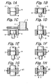
- a mold a used in the method which comprises a tubular body having a bore b extending therethrough to define a mold cavity, as shown in Fig. 1A.
- a lower press core e is also provided, which is inserted into the bore b from the bottom of the mold a and thereby fitted in the bore b .
- the mold a may be either a sintering mold used not only for forming a powder compact therein but also for retaining the powder compact therein during subsequent electrical sintering process or a powder-compact-forming mold used only for forming a powder compact therein while the powder compact thus formed is subjected to sintering process after removed from the mold.
- the mold a and the lower press core e may be formed of any suitable conductive material for electrical sintering process, such as graphite.
- the mold a and the lower press core e may be formed of any suitable iron-based material, such as a steel.
- the mold a with the lower press core e fitted therein is placed on a tray (not shown) and brought to a powder filling position, and the mold a is aligned to the powder filling position with precision.
- the tray is used in order to facilitate the continuous fabrication process and not to prevent the lower press core from dropping off the mold; in fact, the lower press core is fitted tight in the bore of the mold, which could effectively prevent the lower press core from dropping off the mold even if no tray were used but the mold itself were gripped for transportation.
- FIGs. 2 to 15 we will describe an apparatus for automatically loading powder material into a mold, constructed and arranged in accordance with a first embodiment of the present invention, together with an exemplified sequence of operations carried out by the apparatus for loading powder material into a sintering mold, in which electric sintering is effected to the powder compact retained therein.
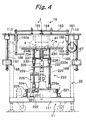
- Figs. 2 and 3 show the whole of the automatic powder material loading apparatus 10 (referred to more simply as the "loading apparatus" hereinafter) of the first embodiment.
- the loading apparatus 10 may be suitably used to form in a sintering mold a multi-layered powder compact comprising layers of different powder materials, which differ from one another in at least one of properties including component(s) of powder material, percentages of components, particle size and particle shape.
- the loading apparatus 10 includes a plurality of powder filling mechanisms arranged in line and used independently for filling different powder materials, respectively, as detailed below. More specifically, the loading apparatus 10 comprises a frame 11 (shown extending in horizontal direction in Figs. 2 and 3), a sintering mold dispenser unit 12 provided at one end (the right-hand end in Figs.
- a powder filling system including a plurality of powder filling mechanisms 14 arranged in line along the length of the frame 11, a measure unit 16 provided on the frame 11 and located next to the powder filling system, a press unit 18 constructed separately from the frame 11 and located next to the left-hand end of the frame 11, a take-out unit 20 for taking our or picking up and sending a sintering mold, and a sintering mold conveyor system 22 (not shown in Fig. 2 nor Fig. 3) for conveying a sintering-mold-and-tray (i.e., a sintering mold together with a tray on which it is placed) from the sintering mold dispenser unit 12 to the press unit 18.
- a sintering-mold-and-tray i.e., a sintering mold together with a tray on which it is placed
- a sintering mold a1 is conveyed together with an associated tray J on which the sintering mold a1 is placed.
- the tray J has a central, circular opening H formed therein, which has a smaller diameter than the bore b of the sintering mold.
- the tray J also has a central, shallow recess formed on its top surface, for receiving the bottom portion of the sintering mold so as to ensure appropriate placement of the sintering mold on the tray J during transportation.
- the sintering mold when stored in the dispenser unit 12, has a lower press core e fitted in the bore b, with the outer peripheral edge of the bottom of the lower press core e being in engagement of the top surface of the tray J along the edge of the central opening H of the tray J. Under this condition, the sintering mold is dispensed by the dispenser unit 12 onto a carrier which is described in detail below.
- the sintering mold conveyor system 22 includes a pair of spaced, horizontal guide rails 221 extending in the longitudinal direction of the elongated frame 11 to cover the entire length of the frame 11.
- the guide rails 221 are mounted on under frame members 111 of the frame 11 as well as on a base plate of the press unit 18.
- the conveyor system 22 further includes a rack 222 extending along the guide rails 221 and a carrier 223 supported by and movable along the guide rails 221.
- the carrier 223 includes a horizontal, flat, movable base plate 224 having four wheels 225 (two are provided on each of right- and left-hand sides (as viewed in Fig.
- the movable base plate 224 is capable of running along the guide rails 221.
- the movable base plate 224 is driven to run along the guide rails 221 by means of a drive motor 226 mounted on the movable base plate 224 and having reduction gears incorporated therein.
- the drive motor 226 has an output shaft with a pinion 227 fixedly mounted thereon and in engagement with the rack 222, so that operation of the drive motor 226 causes the movable base plate 224 to run along the guide rails 221.
- the movable base plate 224 has four bearing sleeves 229a fixedly mounted thereon (two are provided on each side of the base plate 224, with only two being shown in Fig. 4) and four vertical posts 229 supported and guided by the respective bearing sleeves 229a for vertical displacement relative to the movable base plate 224.
- a horizontal, flat, receiving plate 230 is secured to and supported by the upper ends of the four vertical posts 224.
- the receiving plate 230 has a central, circular opening 231 formed therein. When a tray J carrying a sintering mold a1 is placed on the receiving plate 230, the opening 231 is substantially in alignment with the hole b of the sintering mold a1.
- a mount plate 232 is secured to and interconnects the four vertical posts 229 near the middle points of the posts 229.
- a lift plate 233 is provided between the mount plate 232 and the receiving plate 230.
- the lift plate 233 has four bearing sleeves 233a fixedly mounted thereon, for receiving the respective vertical posts 229, such that the lift plate 233 is guided by the vertical posts 229 for vertical displacement.
- the lift plate 233 further has a push-up member 234 fixedly mounted on the top surface thereof, for pushing up the lower press core e fitted in the sintering mold a1 carried by the tray J on the receiving plate 230.
- the mount plate 232 has a drive motor 235 mounted thereon, which comprises an electric motor having reduction gears incorporated therein.
- the drive motor 235 has a vertical output shaft, the axis of which is in alignment with the axis of the opening 231 of the receiving plate 230.
- the output shaft of the drive motor 235 has a screw spindle 236 fixedly connected thereto, so that the operation of the drive motor 235 causes the screw spindle 236 to rotate.
- the lift plate 233 has a nut 237 fixedly mounted thereon and in thread engagement with the screw spindle 236.
- the push-up member 234 has a cylindrical stem with its axis extending in vertical direction and a horizontal top flange 234b extending radially outwardly from the top end of the stem, with an axial bore 234a being formed therethrough to extend in vertical direction (Fig. 5A).
- the screw spindle 236 is received in the axial bore 234a of the push-up member 234.
- the electric motor used in the drive motor 235 comprises a stepper motor capable of positioning control with accuracy allowing positioning errors which are well less than 0.1 mm and typically on the order of 0.01 mm. Other devices may be also used as long as they may provide compatible positioning accuracy.
- the movable base plate 224 has a lift motor (an electric motor) 239 mounted thereon.
- a vertical rod 238 is fixedly connected to the mount plate 232, with the upper end of the rod 238 being secured to the mount plate 232.
- the movable base plate 224 further has a drive mechanism mounted thereon, for operatively interconnecting the output shaft of the lift motor 239 and the vertical rod 238 so as to translate rotary motion of the former into linear motion of the latter.
- the drive mechanism may comprise a rack-and-pinion mechanism, a feed screw mechanism or a roller mechanism comprising a roller in frictional contact with the vertical rod 238.
- the drive mechanism may comprise a rotary nut (not shown) supported for rotation and driven by the lift motor 239, with the vertical rod 238 comprising a screw rod in thread engagement with the rotary nut.
- Such mechanism may typically allows the control of the vertical displacement of the mount plate 232 with accuracy allowing positioning errors less than 0.1 mm.
- the lift motor 239 is operated to rotate the rotary nut
- the mount plate 232 is displaced together with the posts 229 and the receiving plate 230 in a vertical direction relative to the movable base plate 224.
- the carrier 223 conveys a sintering mold a1, when the sintering mold a1 is placed on a tray, which is in turn placed on the receiving plate 230.
- the tray J is a plate-like member having a central, shallow recess formed in its top surface, for receiving the bottom of a sintering mold a1.
- the sintering mold a1 may be placed in position on the tray J as well as held by the tray J by virtue of the central recess. While the positioning and holding of a sintering mold on a tray is provided by the central recess of the tray in this embodiment, other known means may be also used to provide these functions. Further, while the sintering mold used in this embodiment comprises a hollow cylindrical body with a circular cross section, any other sintering molds comprising a tubular body with different cross sections may be also used.
- the movable base plate 224, the mount plate 232 and the lift plate 233 have recesses or cutouts 224', 232' and 233', respectively, which are open toward one direction, facing to one end of the guide rails 221, which direction is referred to as the forward direction of the carrier 233.
- the recesses 224', 232' and 233' are capable of receiving an upright, hollow cylindrical pedestal of the press unit 18 (providing the same function as the lower plunger g of Figs. 1B to 1F, as described in greater detail below), such that the axis of the push-up member 234 may be substantially in alignment with the axis of the cylindrical pedestal.
- the lower press core e is sized such that it may be fitted so tight in the sintering mold a1
- the lower press core e will not be lowered within the mold during the subsequent powder filling operation without any support to the lower press core e .
- the drive motor 235 for lifting up/down the push-up member 234 relative to the mount plate 232 may be replaced by a hydraulic cylinder, as long as the latter is capable of defining the upper limit position of the lower press core e with precision.
- the sintering mold dispenser unit 12 comprises an elevator 120 for storing therein a plurality of sintering molds a1 together with associated trays J each carrying one of the molds a1, and for sequentially lifting down and dispense the sintering molds a1 with trays J.
- the elevator 120 comprises: a pair of horizontal drive shafts 121 provided on opposite sides of the frame 11 (right- and left-hand sides of the frame 11, as viewed in Fig. 7); a pair of horizontal idler shafts 122 associated with the drive shafts 121; and a drive motor (an electric motor) 123 for driving the drive shafts 121 to rotate.
- the drive shafts 121 are supported for rotation by means of respective bearings 121a of a known type and mounted thereby on the upper edges of a pair of right and left side members 112 of the frame 11 (Fig. 7).
- the frame 11 further comprises two pairs of vertical columns 114 for the sintering mold dispenser unit 12, which are mounted on the pair of side members 112.
- the idler shafts 122 are supported for rotation by means of bearings of a known type and mounted thereby at the top ends of the vertical columns 114, such that the idler shafts 122 are provided on opposite sides of the frame 11 and just above the associated drive shafts 121.
- the sintering mold dispenser 12 further comprises a drive train of a known chain-and-sprocket type for transmitting the torque of the drive motor 123 and driving the drive shafts 121 to rotate in opposite directions (i.e., the right- and left-hand drive shafts are driven to rotate in clockwise and counterclockwise directions, respectively, as viewed in Fig. 7). More specifically, the drive train comprises, for each side of the frame 11, a pair of spaced sprockets 125 fixedly mounted on the drive shaft 121 on that side of the frame 11 and a pair of spaced sprockets 126 fixedly mounted on the idler shaft 122 on that side, the sprockets 126 being spaced apart the same distance as the sprockets 125.
- the pair of sprockets 125 on the drive shaft 121 and the pair of sprockets 126 on the idler shaft 122 are operatively connected through a pair of endless chains 127 wound round them.
- two pairs of chains 127 are provided in total, one pair being provided on each side of the frame 11.
- Each pair of chains 127 have a plurality of horizontal, support bars 128 mounted thereon at constant intervals and interconnecting the chains 127 of the pair.
- the pair of drive shafts 121 are driven to rotate in opposite directions and in synchronism, and the phase between the left- and right-hand chain pairs (as viewed in Fig. 7) is adjusted such that the support bars 128 provided on the left-hand chain pair are always kept to be level with their corresponding support bars 128 provided on the right-hand chain pair.
- Each pair of support bars 128 supports a tray J carrying a sintering mold a1, so that a plurality of sintering molds a1 may be stored in the sintering mold dispenser unit 12.
- the drive motor 123 is operated to move the chains 127 a predetermined distance at a time, and in directions as indicated by respective arrows in Fig. 7, so that the trays supported by the support bar pairs are lifted down and the lowest of the trays is dispensed onto the receiving plate 230 of the carrier 223, which is then located under the sintering mold dispenser unit 12.
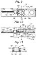
- the powder filling mechanisms 14 are arranged in line along the transportation path of the carrier 223.
- the number of the units 14 should be equal or greater than the number of different powder materials to be used. Since the powder filling mechanisms 14 have the same construction and are used to provide identical functions, only one of them is described in detail.
- the frame 11 includes a pair of upper beams 113 (Fig. 10) extending in the longitudinal direction of the frame 11, i.e., parallel to the guide rails 221.
- the powder filling mechanism 14 comprises a generally rectangular, support plate 141 horizontally fixed on the upper beams 113 of the frame 11 in a known manner.
- the support plate 141 extends perpendicular to the running direction of the carrier 233 and over the transportation path of the sintering mold a1 conveyed by the carrier 223.
- the powder filling mechanism 14 further comprises a pair of horizontal, hopper guide rails 142 mounted on the top surface of the support plate 141 and spaced apart in the running direction of the carrier 223 and a movable hopper 150 provided on the support plate 141 and between the hopper guide rails 142.
- the hopper guide rails 142 extend perpendicular to the running direction of the carrier 223 and over the transportation path of the sintering mold a1.
- the movable hopper 150 is supported and guided by the hopper guide rails 142 for horizontal displacement.
- the support plate 141 has an opening 141a (of a circular shape in the embodiment) formed therein.
- the opening 141a is formed at such position that a sintering mold placed on the carrier 223 may be in alignment therewith, when the carrier 233 has been brought to the powder filling position of the powder filling mechanism 14. Further, the opening 141a is so sized as to be capable of receiving the top end of the sintering mold without any substantial clearance therebetween.
- Each of the hopper guide rails 142 includes: a guide plate 143 defining a horizontal guide surface 143a facing downward; a base plate 144 secured to the support plate 141 in a known manner; and a plurality of support rods 145 interconnecting the guide plate 143 and the base plate 144 with a space left therebetween.
- the movable hopper 150 comprises a hollow cylindrical body 151 having an inner diameter substantially equal to or somewhat greater than that of the bore b of the sintering mold a1 and having a bottom flange 151 extending radially outwardly.
- the bottom flange 151 has a rectangular outer contour as seen in plan, which is nearly square having four sides, of which a pair of opposite sides extend along the hopper guide rails 143.
- Two rollers 153 are provided on each of these sides of the bottom flange 151, for rolling on the guide surface 143a of the corresponding one of hopper guide rails 143.
- the rollers 153 (four, in total) are always in engagement with the guide surfaces 143a, which faces downward as described above, so that the movable hopper 150 is effectively prevented thereby from rising apart from the top surface of the support plate 141.
- the body 151 of the movable hopper 150 is filled with a powder material. While it is generally preferable that the inner cavity of the hopper body 151 has a cross section corresponding to that of the sintering mold into which the powder material is to be filled from the movable hopper 150, other cross sections may be also used to achieve acceptable results. For example, for a sintering mold having a hollow cylindrical body with a circular cross section, we may use a hopper having a tubular body with a square cross section.
- the cross section of the inner cavity of the hopper body 151 may preferably have a size which is either equal to or somewhat greater than that of the cross section of the bore of the sintering mold to be used.
- the preferable relationship may be expressed as D1 ⁇ D2, where D1 and D2 stand for the inner diameters of the bore of the sintering mold and the inner cavity of the hopper body, respectively.
- the movable hopper 150 has a rod 154 having one end connected to the movable hopper 150 on one side (the left-hand side as viewed in Figs. 9 and 10) of the movable hopper 150 and extending parallel to the hopper guide rails 142 (i.e., in the horizontal direction as viewed in Figs. 9 and 10).
- the rod 154 is supported by a linear bearing 155 for sliding movement along the longitudinal direction of the rod 154, with the linear bearing 155 being fixedly mounted on the support plate 141.
- the rod 154 is driven for reciprocal linear motion by means of a drive motor 146 and a suitable drive mechanism of a known type (not shown).
- the drive mechanism may be a rack-and-pinion drive comprising rack-teeth formed on the rod 154 and a pinion in engagement with the rack-teeth and driven by the drive motor 146 for rotation in both directions.
- a drive mechanism may be preferably housed within the casing of the linear bearing 155.
- the position of the rod 154 and thus the position of the movable hopper 150 is detected by a pair of position sensors 147a and 147b, which are mounted on the support plate 141 at positions spaced apart in the moving direction of the rod 154.
- the powder filling mechanism 14 having the arrangement as described above, operates as follows.
- the movable hopper 150 has a sufficient amount of powder material j stored in the cavity of the body 151 and is positioned at one of two waiting positions M and O shown in Fig. 10.
- the lift motor 239 on the carrier 223 is operated to lift up the assembly composed of the receiving plate 230 and the four vertical posts 229, until the top end of the sintering mold a1 on the tray J enters in the opening 141a of the support plate 141 and the top surface c of the sintering mold a1 becomes substantially level with (or flush with) the top surface of the support plate 141.
- the drive motor 235 on the carrier 223 is operated to rotate the screw spindle 236 to lift up the lift plate 233 together with the push-up member 234 relative to the receiving plate 130 and thereby to displace the lower press core e upward relative to the sintering mold a1, until the top surface of the lower press core e is raised to reach the level with which the distance (or depth) of the top surface of the lower press core e from the top surface c of the sintering mold a1 becomes a desired distance (or desired depth).
- the powder filling mechanism 14 is provided with a clamp (not shown) for gripping the sintering mold to secure it to the powder filling mechanism 14.
- the "desired" depth of the top surface of the lower press core from the top surface of the sintering mold a1 depends on the desired amount of powder material to be filled into the sintering mold or the desired thickness of the powder layer to be formed in the sintering mold.
- the "actual" depth of the top surface of the lower press core from the top surface of the sintering mold a1 may be controlled base on the measurement of the vertical position of the push-up member 234 relative to the vertical position of the receiving plate 230, with knowledge of the height of the sintering mold a1 and the height (or thickness) of the lower press core. Then, the movable hopper 150 is operated to make a stroke of movement from the position M to the position O or vice versa.
- the bottom opening (or mouth) of the inner chamber of the movable hopper 150 passes through the top opening (or mouth) of the bore b of the sintering mold a1, then an amount of powder is filled into the bore b of the sintering mold a1 from the movable hopper 150.
- the powder filling operation is completed. Because the bottom surface of the movable hopper 150 is kept in contact against the top surface of the support plate 141 during its stroke, the amount of powder material lust filled into the sintering mold a1 has a flat top surface which is level with the top surface of the sintering mold a1.
- the edge of the bottom surface of the movable hopper 150 serves as a strickle for strickling off any excessive amount of powder material to the level of the top surface of the sintering mold a1.
- the receiving plate 130 of the carrier 223 is lowered together with the sintering mold.
- the lower press core is fitted tight into the bore of the sintering mold so that a significant force is needed for causing displacement of the lower press core relative to the sintering mold, with the result that any unintended lowering of the lower press core relative to the sintering mold will never be caused by gravity.
- the measure unit 16 comprises: a horizontal support plate 161, which is fixedly mounted on the upper beams 113 of the frame 11 and extends over the transportation path of the carrier 223; four bearing sleeves 162a fixedly mounted on the support plate 161; and four vertical rods 162 supported by the respective bearing sleeves 162a for vertical displacement.
- the four bearing sleeves 162a are provided on the support plate 161, with two of them being located at each end (each of the right- and left-hand ends as viewed in Fig. 4) of the support plate 161.
- the measure unit 16 further comprises: a connecting plate 163 secured to the upper ends of the vertical rods 162; a load sensor 164 secured to the support plate 161 at the middle point of the support plate 161; and a pusher 165 fixedly attached to the connecting plate 163 for pushing down the top end of the load sensor 164.
- Each of the vertical rods 162 has a support bar 166, which is connected at the lower end of the associated vertical rods 162 and extends horizontally toward the transportation path of the carrier 223.
- Vertical guide rods 167 for guiding counterweights 168 in vertical direction are fixedly connected to the support plate 161.
- a support bar 166 extending toward the carrier is fixed to the lower end of each of the vertical rods.
- a sintering mold may be brought to the measuring position of the measure unit 16 each time the powder filling operation has been effected to the sintering mold. Alternatively, a sintering mold may be brought to the measuring position only when the powder filling operations for all the powder layers to be formed in the sintering mold have been done.
- the lift motor 239 in the carrier 223 is operated to lift down the receiving plate 130.
- the receiving plate 130 is lifted down below the support bars 166
- the sintering-mold-and-tray placed on the receiving plate 223 is passed to the support bars 166.
- the sintering-mold-and-tray is now supported solely by the support bars 166, and the total weight of the amounts of powder materials having been filled into the sintering mold so far is measured by the load sensor 164, which excludes the weights of the vertical rods 162, the connecting plate 163, the tray J, the sintering mold a1 and the lower press core e . Further, from the measurements thus obtained, the weight of the amount of powder material last filled into the sintering mold can be determined.
- the measurement operation may be performed either before or after the pressing operation which is described in detail below.
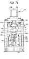
- the press unit 18 comprises a rectangular base plate 181 which is separate from the frame 11; four upright columns 182 fixedly mounted on the base plate 181, one at each corner of the base plate 181; an upright pedestal 183 fixedly mounted on the base plate 181 at the center thereof; a top plate 184 supported by and connected to the upper ends of the columns 182; a press guide 185 guided by the columns 182 for vertical movement between the top plate 184 and the base late 181; an upper plunger or press member 186 fixedly mounted on the press guide 185; an hydraulic cylinder 187 secured to the top plate and having a piston rod 187a connected to the press guide 185.
- the base plate 181 is provided with a pair of guide rails (not shown) mounted thereon, the guide rails forming an elongation of the guide rails 221 mounted on the under frame members 111 of the frame 11, so that the carrier 233 may be operated to run not only along the guide rails 21 on the frame 11 but also along the guide rails on the base plate 181.
- the pedestal 183 has a top end 183a which is so shaped and sized as to be received in the opening 131 of the receiving plate 130 of the carrier 223 as well as in the opening H formed in the tray J.
- the pedestal 183 is of a hollow cylindrical shape and has a cutout 191 formed therein, as shown in Fig. 12B.
- the cutout 191 faces the direction from which the carrier approaches the pedestal 183 and forming a through path between the inside and the outside of the hollow cylindrical pedestal 183.
- the cutout 191 allows a part of the carrier 233 to enter the inside space of the pedestal 183, which part includes the cylindrical stem portion of the push-up member 234, the drive motor 235, the central portion 232a of the mount plate 232 and the central portion 233a of the lift plate 233 (see Figs. 5C and 5D).
- the top flange 234b of the push-up member 234 extends above the top, circular edge of the pedestal 183, with the axis of the push-up member 234 and being substantially in alignment with the axis of the pedestal 183.
- the pedestal 183 is received in the recess or cutout 224' formed in the lift plate 224 of the carrier 223 (Figs. 5B and 5D).
- the upper plunger or press member 186 has a lower end so shaped and sized as to be fitted tight in the bore b of the sintering mold a1.
- the press unit 18 further comprises a pair of hydraulic cylinders (lift cylinders) 188 mounted on the base plate 181 through respective brackets 189 at positions on opposite sides of the pedestal 183.
- the hydraulic cylinders 188 are supported by the corresponding brackets 189 with their piston rods 188a extending upward.
- a pair of support members 190 are attached to the upper ends of the piston rods 188a, respectively.
- the press guide 185 having the upper plunger 186 mounted thereon is placed at its upper position by means of the hydraulic cylinder 187, while the lift cylinders 188 are controlled such that their piston rods 188a are in their retreated position.
- the pedestal 183 is received in the recesses 224', 232' and 233' of the lift plate 224, the mount plate 232 and the lift plate 233, respectively, while the cylindrical stem portion of the push-up member 234, the drive motor 235, the central portion 232a of the mount plate 232 and the central portion 233a of the lift plate 233 together enter the inside space of the pedestal 183 through the cutout 191.
- the axis of the push-up member 234 is substantially in alignment with the axis of the pedestal 183 and the top flange 234b of the push-up member 234 extends above the top edge of the pedestal 183.
- the lift motor 239 is operated to lower the receiving plate 230 of the carrier 223 and thus lower the tray J on which a sintering mold a1 is placed, until the under surface of the top flange 234b of the push-up member 234 come into engagement with the top edge of the pedestal 183, when the top surface of the top flange 234b remains in contact with the bottom surface of the lower press core e fitted in the sintering mold, so that the sintering mold a1 is thereby supported with the lower press core e fitted therein and the amount of powder material filled therein.
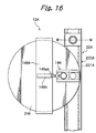
- the hydraulic cylinder 187 is operated to lower the press guide 185 and the upper plunger or press member 186 along the columns 182, so that the powder material filled into the sintering mold is pressed by the upper plunger 186 at a desired pressure and for a desired length of time.
- the powder material in the sintering mold has been more or less compacted, so that the top surface of the resultant powder compact has been sunk from the initial level, i.e., the level of the top surface c of the sintering mold.
- This sinkage can be measured by detecting the relative vertical displacement of the bottom surface of the upper plunger 186 with respect to the top surface of the sintering mold. The detection may be achieved by using a suitable sensor, such as a touch sensor.
- the sinkage produced by the pressing operation is much less than the thickness of any powder layer which may be possibly formed next in the sintering mold.
- the powder compact has to be displaced downward relative to the sintering mold in order to allow for the powder filling operation for the next powder layer (the sinkage produced by compaction of the powder compact plus the subsequent downward displacement of the powder compact relative to the sintering mold will be equal to the thickness of the next powder layer).
- the lift cylinders 188 are operated to extrude their piston rods 188a upward, with the result that the support members 190 attached to the upper ends of the piston rods 188a come into engagement with the receiving plate 230 of the carrier 223 so as to lift up the receiving plate 230.
- the hydraulic cylinder 187 is operated to lift up the upper plunger 186 at the same rate as the receiving plate 230, so that the powder compact is kept pressed. Further, at the same time, the lift motor 239 is operated in direction to lift up the receiving plate 230 (the push-up member 234 is lifted up together with the receiving plate 230). The operations above continue until the receiving plate 230 of the carrier 233 is lifted up to reach the level at which the receiving plate 230 is maintained during conveyance of a sintering mold.
- the upper plunger 186 and the push-up member 234 are now displaced downward relative to the sintering mold, with the powder compact being kept pressed therebetween, until the amount of the downward displacement of the push-up member 234 reaches the desired amount (which depends on the selected amount of powder material to be filled for the next powder layer). In this manner, the powder compact is displaced downward relative to the sintering mold a1.
- the amount of the downward displacement of the powder compact can be detected by measuring the displacement of the push-up member 234.
- the powder compact to be formed is a non-multi-layered powder compact so that only a single powder layer needs to be formed in the sintering mold (such a powder layer usually has a greater thickness than any powder layer in a multi-layered powder compact)
- the amount of the upward displacement of the tray and the sintering mold thereon is controlled such that the vertical position of the powder compact relative to the sintering mold will be the most suitable position for the sintering operation subsequently performed.
- the push-up member 234 is displaced downward relative to the receiving plate 230 by the distance corresponding to the thickness of the next powder layer.
- the push-up member 234 may be further lowered to the waiting position if the under press core need not be supported during the next powder filling operation.
- the powder compact to be formed is a multi-layered powder compact so that a plurality of powder layers need to be formed in the sintering mold, following the powder filling and pressing operations for the last powder layer, the amount of the upward displacement of the tray and the sintering mold thereon is controlled such that the vertical position of the powder compact relative to the sintering mold will be the most suitable position for the sintering operation subsequently performed.
- the fit of the upper plunger 186 in the bore of the sintering mold is a tight fit (in order to prevent escape of any powder which could otherwise occur through a clearance between the bore and the upper plunger 187), the upper plunger 186 tends to drag upward the sintering mold when lifted up for removal from the sintering mold.
- a clamping mechanism (not shown) is provided on the press unit 18 for clamping the sintering mold when the upper plunger 186 is lifted up for removal from the sintering mold.
- the take-out unit 20 serves to sequentially pick up from the carrier 223 trays with sintering molds having been subjected to the pressing operation in the press unit 18 and send them to the next process station.
- the sender unit 20 comprises an elevator 200 having a construction similar to the elevator 120 of the sintering mold dispenser unit 12; therefore, like parts and elements are designated by like reference numerals and not described in detail for simplicity.
- the take-out unit 20 further comprises a first transfer mechanism 201 for transferring a sintering-mold-and-tray from the carrier 233 to the elevator 200 and a second transfer mechanism 210 for transferring a sintering-mold-and-tray from the elevator 200 to the conveyor line for conveying them to the next process station.
- the first transfer mechanism 201 comprises: a pair of horizontal guide rails 203, which are disposed on opposite sides of the elevator 200 and fixedly mounted on an upright sub-frame 114 of the frame 11 through brackets 202; a pair of slide heads 204 supported and guided by the guide rails 203, respectively, for movement along the guide rails 203; and a hydraulic cylinder (serving as an actuator) 205, which is fixedly mounted on the bracket 202 to extend parallel to and along one of the guide rails 203 (the one disposed on the left-hand side as viewed in Fig. 15).
- the ends of the slider heads 204 (the right-hand ends as viewed in Fig. 14) are interconnected through a pushing cross bar 206 extending therebetween.
- the pushing cross bar 206 serves to push a tray J (having a sintering mold placed thereon) in a horizontal direction toward a position at which the tray can be taken and lifted up by the elevator 200.
- the hydraulic cylinder 205 has a piston rod 205a, which is connected at the tip end thereof to an end of that one of the slide heads 204 which is the nearer to the hydraulic cylinder 205 than the other.
- reciprocation movement of the piston rod 205a causes the corresponding reciprocation movement of the slide heads 204 between positions L1 and L2 (shown in Fig. 14).
- the first transfer mechanism 201 further comprises a pair lift cylinders (hydraulic cylinders serving as actuators) 207 disposed on opposite sides of the transportation path of the carrier 223, for lifting up a tray J (having a sintering mold placed thereon) to the level for allowing the pushing cross bar 206 to push and move the tray J.
- the frame 11 includes a pair of horizontal beams 115 (only one of them is shown in Fig. 14) mounted on the pair of side members 112 of the frame 11.
- the first transfer mechanism 201 further comprises a plurality of feed rollers 208, 209 arranged in line (in horizontal direction in Fig. 14) and supported by the pair of horizontal beams 115 for rotation in a known manner.
- the feed rollers 208, 209 are capable of free rotation: when a tray J is pushed by the pushing cross bar 206, it is conveyed by means of the rollers 208, 209 to the position at which it can be picked up by the support bars 128 of the elevator 200.
- the second transfer mechanism 210 comprises a launcher cylinder (a hydraulic cylinder serving as an actuator) 211 for launching a lifted-up tray from the uppermost position in the elevator 200 onto the conveyor line.
- a launcher cylinder a hydraulic cylinder serving as an actuator
- the lift cylinder 207 is operated to lift up the tray.
- the hydraulic cylinder 205 is operated to move the pushing cross bar 26 from the right to the left in Fig. 14, so that the tray is moved by the pushing cross bar 206 to the position at which the tray, having a sintering mold placed thereon, is loaded on the support bars 128 of the elevator 200.
- the tray thus loaded on the support bars 128 is lifted up by the elevator 200 to the uppermost position in the elevator 200, and then pushed out of the elevator 200 to the left in Fig. 14 and launched onto the conveyor line by the launcher cylinder 211.
- a press core installer for fitting an upper press core m into the upper end portion of the bore b of a sintering mold, in which a finished powder compact is housed.
- the press core installer may comprise, for example, an industrial robot, which is operative to pick up an upper press core m by gripping its upper end; bring the upper press core m to the position just above the sintering mold a1, which is at this point of time placed on the carrier 233 located at the position as indicated by imaginary lines in Fig. 14; and lift down the upper press core m to fit it into the bore b of the sintering mold a1.
- an industrial robot is well known in the art and thus is not described in more detail here.
- Sintering molds a1 are individually placed on associated trays J during transportation through the apparatus 10. As described, the trays J have an opening H formed therein.
- the carrier 233 is operated to move sequentially to the selected ones of the powder filling mechanisms 14 in the order appropriate for forming the plurality of powder layers in the sintering mold.
- the carrier 223 is moved to the first of the selected powder filling mechanisms (typically, the carrier 223 is moved first to the powder filling mechanism located at the position A or position K), it is stopped under that powder filling mechanism and then positioned to the powder filling position of that mechanism with precision.
- the receiving plate 230 is lifted up to raise the sintering mold a1 with the tray J to a predetermined level, at which the upper end of the sintering mold a1 is received in the opening 141a of the support plate 141 of the powder filling mechanism.
- the push-up member 234 is lifted up a predetermined distance relative to the receiving plate 230 so as to raise the lower press core e to such a level that is appropriate for the filling of a desired amount of powder material into the sintering mold for the first powder layer.
- the powder filling mechanism is operated in the manner described above so that the desired amount of powder material is filled into the bore of the sintering mold a1.
- the sintering mold is transported by the carrier 223 to the pressing position of the press unit 18, which then serves to press at a desired pressure the amount of powder material in the sintering mold, so as to form a pre-compressed powder compact. If another powder filling operation has to be carried out for the next powder layer to be formed in the sintering mold, either the sintering mold is displaced upward relative to the powder compact or the powder compact is displaced downward relative to the sintering mold while the powder compact is kept pressed, such that the vertical position of the powder compact within the sintering mold is adjusted to such a position that is appropriate for the filling of a desired amount of powder material into the sintering mold for the next powder layer.
- the press unit 18 releases the sintering mold a1, and the carrier 223 transports the sintering mold a1 to the measuring position of the measure unit 16, at which the weight of the powder material in the sintering mold is measured in the manner described above.
- This sequence of operations is repeated for each of the powder layers to be formed in the sintering mold, in which different powder filling mechanisms 14 are used for filling different powder materials into the sintering mold.
- the number of the total iterations of this sequence is equal to the number of the powder layers to be formed in the sintering mold.
- FIG. 16 shows a schematic plan view of the automatic powder material loading apparatus 10A of the second embodiment.
- the automatic powder material loading apparatus 10A has a plurality of powder filling mechanism mounted on a rotary table so that different powder materials may be filled into and pressed within a sintering mold while the sintering mold is held at one position. This is a primary difference of the apparatus 10A from the that of the first embodiment described above.
- the automatic powder material loading apparatus 10A comprises a conveyor system 22A for conveying sintering molds together with associated trays along a predefined conveyance path; and a horizontal rotary table 24A supported for rotation about a vertical axis and driven for indexing movement by means of an indexing drive mechanism of a known type (not shown).
- the rotary table 24A partially extends over the conveyance path of the conveyor system 22A.
- the automatic loading apparatus 10A further comprises a lift/support unit 25A provided at a position at which a part of the rotary table 24A extends over the conveyor system 22A, for receiving a sintering mold from the conveyor system 22A and lifting up and supporting the received sintering mold; and a press unit 26A disposed above the lift/support unit 25A, for cooperating with the lift/support unit 25A to press at a desired pressure the amount of powder material filled into the sintering mold.
- a lift/support unit 25A provided at a position at which a part of the rotary table 24A extends over the conveyor system 22A, for receiving a sintering mold from the conveyor system 22A and lifting up and supporting the received sintering mold
- a press unit 26A disposed above the lift/support unit 25A, for cooperating with the lift/support unit 25A to press at a desired pressure the amount of powder material filled into the sintering mold.
- the automatic powder material loading apparatus 10A further comprises a sintering mold dispenser unit (not shown) for dispensing sintering molds with associated trays onto the conveyor system 22A and a take-out unit (not shown) for picking up sintering molds with associated trays from the conveyor system 22A to send them to the next station, both of which are similar to those used in the first embodiment with apparent modifications effected thereto for meeting the requirements of the conveyor system 22A.
- the conveyor system 22A comprises a pair of horizontal guide rails 221A for supporting and guiding a tray J carrying a sintering mold, in which the tray J is supported at its side edges (with respect to the conveyance direction).
- the conveyor system 22A further comprises a driving device 220A for driving trays J supported by the guide rails 221A to move along the rails 221A.
- the driving device 220A may be a conventional chain drive comprising a pair of drive sprockets (not shown), a pair of idler sprockets (not shown) and a pair of endless chains 222A wound round these sprockets and extending along the respective guide rails 221A.
- Each endless chain 222A has a series of claws 223A (Fig. 18) provided therealong at constant intervals, for engaging with and pushing respective trays when the endless chain 222A is driven to circulate.
- the guide rails 221A may be provided with a series of rollers at constant intervals for facilitating smooth movement of the trays.
- the guide rails 221A may be provided with a pair of sub-rails extending parallel to and above the guide rails for preventing trays from rising off the guide rails 221A.
- the powder filling mechanism 14A is similar in construction to the powder filling mechanism 14 used in the first embodiment, except for some differences that the powder filling mechanism 14A comprises a movable hopper which is movable on a horizontal support plate between position P (at which the support plate has no opening) and position Q (at which the support plate has an opening) and that each powder filling mechanism 14A does not have its own hopper drive mechanism but a single hopper drive mechanism is used to drive any of the movable hoppers provided on the rotary table.
- the powder filling mechanism 14A comprises a movable hopper which is movable on a horizontal support plate between position P (at which the support plate has no opening) and position Q (at which the support plate has an opening) and that each powder filling mechanism 14A does not have its own hopper drive mechanism but a single hopper drive mechanism is used to drive any of the movable hoppers provided on the rotary table.
- the rotary table 24A which is supported for rotation about the vertical axis as described above, has a plurality of openings 241A formed therein (Fig. 17) along its peripheral edge at constant angular intervals.
- the number of the openings 241A is equal to the number of the powder filling mechanisms 14A provided for the apparatus; however, Fig. 16 shows only one of the powder filling mechanisms 14A with the associated one of the openings 241A.
- a support frame 148A extend over the rotary table 24A.
- the hopper drive mechanism has an actuator comprising a hydraulic cylinder 149A with a piston rod 149a.
- the hydraulic cylinder 149A has a chuck of a known type attached to the tip end of the piston rod 149a, for selectively gripping one of the movable hoppers 150A.
- Each movable hopper 150A includes a hopper body 151A having an upright pin attached thereto, which is adapted to be gripped by the chuck of the hopper drive mechanism.
- the rotary table 24A is driven for indexing movement by means of the indexing drive mechanism of a known type (not shown), so that the rotary table is indexed or rotated about the vertical axis at constant intervals or at a predetermined pitch, which is equal to the pitch between adjacent two of the powder filling mechanisms 14A provided on the rotary table 24A.
- the lift/support unit 25A comprises: a base plate 251; a plurality of vertical guide rods 252A fixedly mounted on the base plate 251; a lift bed 253A guided by the vertical guide rods 252A and driven by a feed screw mechanism of a known type (not shown) for vertical displacement; a vertical screw spindle 254A supported by the lift bed 253A and driven by a drive motor (an electric motor) 256A of a known type; and a lower plunger 255A guided by the lift bed 253A for vertical displacement.
- the lower plunger 255A is received in a center hole formed in the upper end of the lift bed 253A and is capable of projecting upward from the top surface of the lift bed 253A.
- the lower plunger 255A has a vertical threaded hole extending therethrough, with which the vertical screw spindle 254A is in thread engagement, so that by rotation of the screw spindle 254A the lower plunger 255A is lifted up/down relative to the lift bed 253A.
- the lower plunger 255A when lifted up, enters in the opening 141aA of the support plate 141A of the powder filling mechanism 14A so as to push up the lower press core e fitted in the sintering mold.
- the upper end of the lift bed 253A is capable of engaging with the bottom of a tray so as to lift up the tray.
- the press unit 26A comprises a press cylinder (an hydraulic cylinder) 261A, which is disposed just above the lift/support unit 25A and supported by a suitable support frame (not shown) and has a piston rod 262A extending in vertical direction.
- the press unit 26 further comprises an upper plunger or press member 263A attached to the tip end (i.e., the lower end) of the piston rod 262A.
- the upper plunger 263A of the press unit 26A and the lower plunger 255A of the lift/support unit 25A cooperate with each other to press the powder material in the sintering mold.
- the automatic powder material loading apparatus 14A of the second embodiment operates as follows.
- the lift bed 253A of the lift/support unit 25A is lifted up to raise the tray J to a level at which the upper end of the sintering mold a1 is received in the opening 141aA of the support plate 141A and the top surface of the support plate 141A becomes level with the top surface of the sintering mold a1.
- the lower plunger 255A is lifted up to displace upward the lower press core e fitted in the bore b of the sintering mold a1, until the distance (or depth) of the top surface of the lower press core e from the top surface of the sintering mold is reduced to a desired distance (or desired depth), which corresponds to the thickness of the first layer of powder to be filled into the mold.
- the selected one of the powder filling mechanisms 14A is operated to carry out the powder filling operation for the first powder layer.
- the press cylinder 261A of the press unit 26A is operated to lower the upper plunger or press member 263A to press at a desired pressure the amount of powder material in the sintering mold, so as to form a powder compact of the first powder layer.
- the upper and lower plungers or press member 263A and 255A are displaced downward while keeping the powder compact of the first layer in the sintering mold pressed therebetween, until the thickness of the space defined within the sintering mold and above the powder compact of the first powder layer is increased to reach a desired thickness (which corresponds to the thickness of the second layer of powder material to be filled next).
- the upper plunger is lifted up to leave the sintering mold.
- the rotary table is then indexed to bring the powder filling mechanism 14A that stores the powder material for the second powder layer to the powder filling position, in order to allow that powder filling mechanism 14A to carry out the powder filling operation for the second powder layer.
- the sequence of operations described above is repeated for each of the powder layers to be formed in the sintering mold one on another. In this manner, a multi-layered powder compact is finished while the sintering mold is held at the powder filling position during the whole sequence of the powder filling operations.
- the upper and lower plungers 263A and 255A are lowered while keeping the finished powder compact in the sintering mold pressed therebetween, until the multi-layered powder compact is brought to a desired vertical position relative to the sintering mold.
- the whole sequence of operations for loading powder in the sintering mold is completed at this point of time.
- the upper plunger 263A is fitted tight in the bore of the sintering mold in order to prevent escape of any powder from the sintering mold (if there were clearance between the outer surface of the upper plunger and the inner surface of the bore of the mold, some of the powder could possibly escape through the clearance), so that the upper plunger tends to pull up the sintering mold when lifted up.
- a clamp (not shown) is provided to grip the sintering mold to retain it at the powder filling position.
- the loading apparatus 10B comprises a rotary table, a plurality of powder filling mechanisms and a press unit, all of which have the same construction and function as those used in the second embodiment and thus are not described in detail.
- the automatic powder material loading apparatus 10B further comprises a conveyor system 22B.
- the conveyor system 22B comprises a pair of horizontal guide rails 221B and a carrier 223B guided by and capable of running along the guide rails 221B.
- the carrier 223B comprises a horizontal, rectangular, movable base plate 224B and a plurality of linear bearings 225B mounted on the movable base plate 224B.
- the linear bearings 225B are guided and supported by the guide rails 221B for sliding movement therealong.
- the movable base plate 224B has a plurality of (five, in this embodiment) openings 226aB formed therein.
- the movable base plate 224B also has four small holes for each opening 226aB, arranged around the associated opening 226aB along a circle at intervals of ninety degrees.
- the carrier 223B is driven to move along the guide rails 221B by means of a drive mechanism comprising a screw spindle 222B extending along one of the guide rails 221B and a nut 227B mounted on the carrier 223B and in thread engagement with the screw spindle 222B.
- the screw spindle 222B is supported by bearings of a known type for rotation and is driven by an electric motor.
- the movable base plate 224B has five stop mechanisms 270B one for each of the five openings 226aB, for limiting upward displacement of a sintering mold a1' placed on the movable base plate 224B.
- Each stop mechanism 270B comprises: a pair of support blocks 271B provided on opposite sides of the opening 225B and fixedly mounted on the base plate 224B; a pair of engagement pins 272B each provided on the top of the associated one of the support blocks 271B and having a stem and a flat, enlarged head; and a stop member 273B capable of placement on and attachment to the tops of the support blocks 271B.
- the stop member 273B has a central opening 274B for receiving the upper portion of a sintering mold a1' and a pair of recesses 275B for receiving the stems of the engagement pins 272B.
- the stop mechanism 270B is adapted for manual setting. After a sintering mold a1' is placed in position on the movable base plate, the stop member 273B is placed on the tops of the support blocks 271B as shown by imaginary lines in Fig. 22, and then rotated in clockwise direction as viewed in Fig. 22 so that the stems of the engagement pins 272B are received in the recesses 275B. In this manner, setting of the stop mechanism 270B is completed. This setting may be manually performed.
- the lift/support unit 25B used in the powder material loading apparatus 10B of the third embodiment comprises: a lift plate 253B guided by vertical guide rods (not shown) for vertical displacement and a lift cylinder (a hydraulic cylinder serving as an actuator) 252B for lifting up/down the lift plate 253B.
- An electric drive motor 256B is supported by the lift plate 253B through guide members (not shown) for guiding the drive motor 256B for vertical displacement relative to the lift plate 256B.
- the drive motor 256B has a vertical output shaft, to which a vertical screw spindle 254B is fixedly connected.
- the lift plate 253B has a nut 259B fixedly mounted thereon, which is in thread engagement with the screw spindle 254B.
- a lower plunger or press member 255B is attached to the upper end of the screw spindle 254B.
- the lift plate 253B further has a plurality of (four, in this embodiment, of which only two are shown in Fig. 25) vertical push rods 257B fixedly connected thereto at their lower ends.
- the push rods 257B extend through respective holds 226bB formed in the movable base plate 224B and serve to push up the bottom of a rectangular tray J (having a sintering mold placed thereon) at its four corners.
- the lift/support unit 25B used in the powder material loading apparatus 10B of third embodiment operates as follows.
- the lift cylinder 252B is operated to lift up the lift plate 224B, so that the push rods 257B connected to the lift plate 224B push up the tray J to raise the sintering mold a1' placed on the tray J.
- the upper portion of the sintering mold a1' thereby enters in the opening 144B of the support plate 141B of the powder filling mechanism 14B and the top surface of the sintering mold becomes level with the top surface of the support plate 141B, when a shoulder of the sintering mold a1' formed on the outer side surface thereof comes into engagement with the edge of the opening 274B of the stop member 273B so that the upward displacement of the sintering mold is stopped.
- the drive motor 256 is operated to lift up the lower plunger 255B to displace upward the lower press core fitted in the sintering mold, until the distance (or depth) of the top surface of the lower press core from the top surface of the sintering mold becomes a desired distance (or desired depth), which corresponds to the thickness of the first layer of powder material to be filled into the sintering mold.
- the subsequent operations are the same as those of the second embodiment described above, and thus not described for avoiding redundancy.
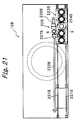
- the movable base plate can bear only a limited (five, in this embodiment) sintering molds, so that after the last of the five sintering molds has been loaded with powder material(s), the movable base plate 224B is moved to the rightmost position as viewed in Fig. 21 and the sintering molds in which the powder is loaded are taken out from the movable base plate. Then the movable table is returned back to the leftmost position as viewed in Fig. 21, where new sintering molds are placed thereon, and the next sequence of operations for loading powder material (s) into the new sintering molds is repeated.
- a limited (five, in this embodiment) sintering molds so that after the last of the five sintering molds has been loaded with powder material(s), the movable base plate 224B is moved to the rightmost position as viewed in Fig. 21 and the sintering molds in which the powder is loaded are taken out from the movable base plate. Then the mov
Abstract
Description
- The present invention generally relates to method and apparatus for automatically loading powder material into a mold and, more particularly, to such method and apparatus for automatically loading a desired amount of powder material into a mold which comprises a tubular body having a bore extending therethrough. The mold may be either a sintering mold used for sintering the powder material loaded therein during sintering process or a powder-compact-forming mold used only for forming a powder compact therein while the powder compact thus formed is subjected to sintering process after being removed from the mold.
- There have been provided various powder material loading apparatus for loading an amount of powder material into a sintering mold to form a powder compact in the mold, which is retained in the mold during a subsequent sintering process, such as an electrical sintering process. However, there has not been proposed an idea of a continuous fabrication process for obtaining sintered products, including the steps of: loading an amount of powder material into a sintering mold in the form of a plurality of layers; heating the powder compact retained in the mold for sintering; and removing the sintered product from the mold. This idea has not been proposed primarily because conventional electrical sintering techniques require a relatively long time to complete the sintering process. In consequence thereof, any of conventional automatic powder material loading apparatus was not intended for such a continuous fabrication process but provides solely the function for loading powder material into a mold.
- Recently, many improvements has been made in electrical sintering methods. For example, Pulsed Current Energizing Sintering (or Pulsed Electric Current Sintering) method using a pulsed current and including Spark-Plasma Sintering, Electric-Discharge Sintering and Plasma-Activated Sintering methods proposed by the applicant of this application has been improved. According to the improved Pulsed Current Energizing Sintering, sintering time is drastically shortened. Such shorter sintering time provides the possibility of realizing a continuous fabrication process for obtaining sintered products, including the above mentioned steps. Therefore, there have now arisen demands for such a method and apparatus for loading powder material into a mold that may be suitably used for such a continuous fabrication process.
- In addition, by virtue of newer electrical sintering techniques, such as those mentioned above, such materials that were difficult to bond together through any older techniques can be now bonded together with ease into a unitary sintered product. Examples of such materials are: a stainless steel vs. copper; a ceramic vs. a metal; etc. Such a unitary sintered product of two different powder materials may be fabricated to have two-layered structure composed of two layers bonded together and each made of a pure powder material; however, the characteristics of such a sintered product can be improved by adding at least one middle layer to create such multi-layered structure in that the middle layer is made of a mixture of the two powder materials. Further, such multi-layered structure may be also used with advantageous for a sintered product including three or more layers made of respective powder materials which are identical in composition and differ from one another only in particle size, wherein the powder materials for the layers have their particle sizes gradually increasing from the layer on one side of the product toward the other side. Such a sintered product may have gradient functionality (i.e., the gradual variation in properties of the sintered product from one side of the product to the other) so as to achieve more improved characteristics. In order to fabricate a sintered product having gradient functionality, it is required to load different powder materials, which differ from one another in at least one of properties including component(s) of powder material, percentages of components, particle size and particle shape, into a mold so as to form corresponding powder layers of desired thickness with precision. While there have been proposed various automatic powder material loading apparatus, none of them is capable of loading different powder materials into a mold to form a multi-layered powder compact in a fully automated manner. In addition, in order to fabricate high-quality sintered products having gradient functionality with good reproducibility, not only the capability of forming a multi-layered powder compact but also other various capabilities are required, so it is the case that none of conventional powder material loading apparatus is suitable for fabrication of sintered products having gradient functionality.
- In view of the foregoing, it is an object of the present invention to provide a method and apparatus for automatically loading powder material into a mold, in which different powder materials may be loaded into a mold, which may be either a sintering mold or a powder-compact-forming mold, so as to form a plurality of powder layers one on another in the mold in a fully automated manner.
- It is another object of the present invention to provide a method and apparatus for automatically loading powder material into a mold, in which the powder material loading sequence may be carried out in a fully automated manner, by utilizing the step of filling an amount of powder material into a mold followed by the step of strickling off any excessive amount of powder material to the level of the top surface of the mold.
- It is a further object of the present invention to provide a method and apparatus for automatically loading powder material into a mold, in which different powder materials, differing from one another in at least one of properties including component(s) of powder material, percentages of components, particle size and particle shape, may be loaded into a mold so as to form a plurality of powder layers one on another in the mold in a fully automated manner, by utilizing the step of filling an amount of powder material into a mold followed by the step of strickling off any excessive amount of powder material to the level of the top surface of the mold.
- It is a still further object of the present invention to provide a method and apparatus for automatically loading powder material into a mold, in which high-quality sintered products may be fabricated by utilizing the step of pressing at a desired pressure the layer of powder material filled into the mold.
- It is a yet further object of the present invention to provide a new powder filling mechanism, which is capable of filling an amount of powder material into a mold, such as a sintering mold or a powder-compact-forming mold, so as to form a powder layer in the mold with precision.
- In accordance with an aspect of the present invention, there is provided a method of automatically loading a desired amount of powder material into a tubular mold having a bore extending therethrough, the method comprising the steps of: providing the mold with a lower press core fitted in a lower end of the bore; bringing the mold with the lower press core fitted therein to a powder filling position; filling an amount of powder material into the mold and strickling off any excessive amount of powder material to the level of a top surface of the mold; and pressing at a desired pressure the amount of powder material in the mold to form a powder compact.
- In a preferred embodiment of the present invention, the mold may comprise a sintering mold and the lower press core may have a top surface. In such case, the method may further comprise the steps of: determining the depth of the top surface of the lower press core from the top surface of the sintering mold; displacing the powder compact with the lower press core relative to the sintering mold so as to bring the powder compact to a desired position in the sintering mold; and fitting an upper press core into the bore of the sintering mold above the powder compact. Alternatively, the mold may comprise a powder-compact-forming mold and the lower press core may have a top surface. In such case, the method may further comprise the step of: determining the depth of the top surface of the lower press core from the top surface of the powder-compact-forming mold; and displacing the powder compact with the lower press core relative to the powder-compact-forming mold so as to remove the powder compact and the lower press core from the powder-compact-forming mold.
- In another preferred embodiment of the present invention, the method may further comprise the step of repeating the filling/strickling step a number of times so as to form in the mold a multi-layered powder compact comprising layers of different powder materials, which differ from one another in at least one of properties including component(s) of powder material, percentages of components, particle size and particle shape. Further, in such embodiment, the method may comprise the step of repeating the pressing step subsequent to every repetition of the filling/strickling step or, alternatively, may comprise the step of repeating the pressing step subsequent to every two or more repetitions of the filling/strickling step.
- In a further preferred embodiment of the present invention, different powder materials may be stored in individual hoppers, wherein the powder filling position may be defined at a single position common to all of the hoppers, and wherein the method may further comprise the step of bringing the hoppers sequentially to the single powder filling position. Alternatively, different powder materials may be stored in individual hoppers, wherein the powder filling position is defined at a number of positions one for each of the hoppers, and wherein the method may further comprise the step of bringing the mold sequentially to the number of powder filling positions in the order appropriate for forming the plurality of layers in the mold. In addition, the weight of the amount of powder material filled into the mold may be measured after the filling/strickling step is performed.
- In accordance with another aspect of the present invention, there is provided an apparatus for automatically loading a desired amount of powder material into a tubular mold having a bore extending therethrough, the apparatus comprising: a mold conveyor system for supporting and conveying the mold with a lower press core fitted in the bore; a powder filling mechanism for filling an amount of powder material into the mold, the powder filling mechanism being located at a powder filling position defined along a transportation path of the mold conveyed by the mold conveyor system; and a press unit for pressing at a desired pressure the amount of powder material in the mold to form a powder compact.
- In a preferred embodiment of the present invention, the mold conveyor system may comprise: a guide rail extending to cover a predetermined range; and a carrier movable along the guide rail and capable of supporting for vertical displacement the mold with the lower press core fitted in the bore. The powder filling mechanism may comprise: a hopper located above a transportation path of the carrier and adapted to store an amount of powder material therein; and a strickle mechanism for strickling off any excessive amount of powder material, being filled into the mold from the hopper, to the level of a top surface of the mold. Further, the press unit may comprise: a lower plunger for pressing upward the lower press core fitted in the mold; and an upper plunger for pressing downward the amount of powder material in the mold.
- In another preferred embodiment of the present invention, a plurality of the powder filling mechanisms may be provided, in which different powder materials are stored, respectively, differing from one another in at least one of properties including component(s) of powder material, percentages of components, particle size and particle shape, wherein the plurality of powder filling mechanisms may be arranged in line along the transportation path of the carrier. Further, the hopper may be movable relative to the mold as held at the powder filling position and movable on a plane of the top surface of the mold as held at the powder filling position, and the hopper may form a part of the strickle mechanism.
- In a further preferred embodiment of the present invention, the carrier may comprise: a movable base; a receiving plate for supporting the mold, the receiving plate being supported by the movable base for vertical displacement relative to the movable base; a push-up member for displacing the lower press core fitted in the bore of the mold when the mold is supported by the receiving plate, the push-up member being supported by the receiving plate for vertical displacement relative to the receiving plate; and a drive unit for driving the push-up member to make displacement. Further, the apparatus may further comprise a measure unit for measuring the weight of the sintering mold with the amount of powder material filled into the mold, so as to measure the weight of the amount of powder material filled into the mold.
- In a still further preferred embodiment of the present invention, the powder filling mechanism may have a single powder filling position. The powder filling mechanism may comprise: at least one hopper movable to and from the single powder filling position and adapted to store an amount of powder material therein; and a strickle mechanism for strickling off any excessive amount of powder material, being filled into the mold from the hopper, to the level of the top surface of the mold. Further, the press unit may comprise a lower press member located at the powder filling position, for pressing upward the lower press core fitted in the mold; and an upper press member for pressing downward the amount of powder material in the mold. Moreover, the mold conveyor system may comprise: a guide rail; a movable base guided by the guide rail for movement along the guide rail and having a number of holes formed therein and arranged in line, each of the holes being adapted to be aligned with the bore of the mold; a stop member attached to the movable base, for limiting upward displacement of the mold; and a drive unit for driving the movable base to move along the guide rail in both directions, whereby the movable base is capable of carrying the same number of the mold as that of the holes at one time.
- In a yet further preferred embodiment of the present invention, the powder filling mechanism may further comprise a rotary table capable of indexing movement. The hopper may be movable relative to the mold held at the powder filling position and movable on a plane of the top surface of the mold held at the powder filling position, and thereby the hopper may form a part of the strickle mechanism. The at least one hopper may comprise a plurality of hoppers provided on the rotary table at circumferentially spaced positions with respect to the axis of the rotary table, the plurality of hoppers being capable of individual movement, wherein different powder materials may be stored in the plurality of hoppers, respectively, differing from one another in at least one of properties including component(s) of powder material, percentages of components, particle size and particle shape.
- In accordance with a further aspect of the present invention, there is provided a powder filling mechanism for filling powder material into a mold which has a bore opening at a top end thereof, the mechanism comprising: a support plate having a top surface and a hole for receiving the upper end of the mold, wherein the upper end of the mold may be fitted in the hole without any substantial clearance therebetween and with a top surface of the support plate and the top surface of the mold being substantially flush with each other; and a hopper having a bottom surface and so disposed as to be movable on the top surface of the support plate with the bottom surface being in contact with the top surface of the support plate, the hopper having an amount of powder material stored therein. The hopper has a bottom opening for dispensing powder material, which opens at the bottom surface and has a size equal to or greater than that of a top opening of the bore of the mold, wherein the hopper is movable on the top surface of the support plate and across the top surface of the mold.
- In a preferred embodiment of the present invention, the hopper may be movable between a first position at which the bottom opening of the hopper is closed by the support plate and a second position at which the bottom opening of the hopper is in alignment with the hole in the support plate, whereby powder filling is completed by a pair of strokes of the hopper from the first position to the second position and then back to the first position. Alternatively, the hopper may be movable along a straight path between first and third positions at which the bottom opening of the hopper is closed by the support plate, wherein the hopper passes by a second position during a stroke between the first and third positions, at which the bottom opening of the hopper is in alignment with the hole in the support plate, whereby powder filling is completed by a single stroke of the hopper from one of the first and third positions to the other.
- The above and other objects, features and advantages of the present invention will be apparent from the following detailed description of preferred embodiments thereof, reference being made to the accompanying drawings, in which:
- Figs. 1A to 1H are section views of a sintering mold, illustrating principles of a method of automatically loading powder material into a mold, in accordance with the present invention;
- Fig. 2 is a side elevation view of an apparatus for automatically loading powder material into a mold, constructed and arranged in accordance with a first embodiment of the present invention;
- Fig. 3 is a plan view of the automatic powder material loading apparatus of Fig. 2;
- Fig. 4 is a front elevation view of a carrier and a measure unit of the automatic powder material loading apparatus of Fig. 2, showing the carrier partially cut away;
- Fig. 5A is a side elevation view, partially sectioned, of the carrier as viewed in the direction of arrows Z-Z in Fig. 4;
- Fig. 5B is a section view of the carrier as viewed in the direction indicated by arrows B-B in Fig. 5A;
- Fig. 5C is a section view of the carrier as viewed in the direction indicated by arrows C-C in Fig. 5A;
- Fig. 5D is a section view of the carrier as viewed in the direction indicated by arrows D-D in Fig. 5A;
- Fig. 6 is a side elevation view of the measure unit of Fig. 4 as viewed in the direction square to that in Fig. 4;
- Fig. 7 is a front elevation view of a sintering mold dispenser unit;
- Fig. 8 is a side elevation view of the sintering mold dispenser unit of Fig. 7 as viewed in the direction square to that in Fig. 7;
- Fig. 9 is a plan view of a powder filling mechanism;
- Fig. 10 is a longitudinal section view of the powder filling mechanism of Fig. 9;
- Fig. 11 is a cross section view of the powder filling mechanism of Fig. 9 taken along line U-U of Fig. 9;
- Fig. 12 is a front elevation view of a press unit;
- Fig. 13A is a side elevation view of the press unit of Fig. 12 as viewed in the direction square to the viewing direction of Fig. 12;
- Fig. 13B is a enlarged plan view of the pedestal of the press unit of Fig. 12;
- Fig. 14 is a side elevation view of a sender unit;
- Fig. 15 is a front elevation view of the sender unit of Fig. 14 as viewed in the direction square to the viewing direction of Fig. 14;
- Fig. 16 is a schematic plan view of an apparatus for automatically loading powder material into a mold, constructed and arranged in accordance with a second embodiment of the present invention;
- Fig. 17 is a section view of the apparatus of Fig. 16 taken along line V-V in Fig. 16;
- Fig. 18 is an enlarged section view of the apparatus of Fig. 16 taken along line W-W in Fig. 16;
- Fig. 19 is a plan view of a powder filling mechanism;
- Fig. 20 is a section view of the powder filling mechanism of Fig. 19;
- Fig. 21 is a schematic plan view of a part of an apparatus for automatically loading powder material into a mold, constructed and arranged in accordance with a third embodiment of the present invention;
- Fig. 22 is an enlarged plan view of a carrier used in the automatic powder material loading apparatus of Fig. 21;
- Fig. 23 is an enlarged cross section view taken along line X-X in Fig. 21;
- Fig. 24 is an enlarged cross section view taken along line Y-Y in Fig. 22; and
- Fig. 25 is an enlarged cross section view of a lift/support unit used in the apparatus of Fig. 21.
-
- With reference now to the accompanying drawings, preferred embodiments of the present invention will be described in detail.
- Referring first to Figs. 1A to 1H, we will describe the principles of a method of automatically loading powder material into a mold, in accordance with the present invention. (1) First, a mold a used in the method is provided, which comprises a tubular body having a bore b extending therethrough to define a mold cavity, as shown in Fig. 1A. A lower press core e is also provided, which is inserted into the bore b from the bottom of the mold a and thereby fitted in the bore b. The mold a may be either a sintering mold used not only for forming a powder compact therein but also for retaining the powder compact therein during subsequent electrical sintering process or a powder-compact-forming mold used only for forming a powder compact therein while the powder compact thus formed is subjected to sintering process after removed from the mold. In the former case, the mold a and the lower press core e may be formed of any suitable conductive material for electrical sintering process, such as graphite. In the latter case, the mold a and the lower press core e may be formed of any suitable iron-based material, such as a steel. The mold a with the lower press core e fitted therein is placed on a tray (not shown) and brought to a powder filling position, and the mold a is aligned to the powder filling position with precision. It is noted that the tray is used in order to facilitate the continuous fabrication process and not to prevent the lower press core from dropping off the mold; in fact, the lower press core is fitted tight in the bore of the mold, which could effectively prevent the lower press core from dropping off the mold even if no tray were used but the mold itself were gripped for transportation.
- (2) Subsequently, the mold a is fixedly held at the powder filling position while the lower press core e is pushed up by a push-up rod f, as shown in Fig. 1B, so that the lower press core e is displaced in vertical direction relative to the mold a (which is fixedly held at this point of time), until the distance (or depth) of the top surface of the lower press core e from the top surface c of the mold a becomes a desired distance (or desired depth). The desired depth depends on a desired amount of powder material to be filled into the mold a and thus on a desired thickness of the powder layer to be formed in the mold a.
- (3) Thereafter, as shown in Fig. 1C, the desired amount of powder material j is filled into the space h defined by the mold a and the top surface of the lower press core e by means of a powder filling mechanism, which also serves as a strickle for strickling off any excessive amount of powder material to the level of the top surface of the mold, as described later in greater detail. When the powder filing operation has been done, the amount of powder material j filled into the space h forms a layer having its top surface level with (or flush with) the top surface c of the mold a.
- (4) Then, as shown in Fig. 1D, the amount of powder material j in the mold a is pressed at a desired pressure by lowering an upper plunger k while the lower press core e is held stationary by a lower plunger g supporting the bottom of the lower press core e so as to form a powder compact. The desired pressure depends on the properties of the powder material to be filled, such as component material(s) and/or particle size of the powder material, and is selected to a pressure which ensures that satisfactory final products may be obtained after sintering.
- (5) The apparatus may be used to form in the mold a multi-layered powder compact comprising layers of different powder materials, differing from one another in at least one of properties including component(s) of powder material, percentages of components, particle size and particle shape. In the case where such a multi-layered powder compact is to be formed, following the pressing operation of powder material in the mold to form a powder compact, as carried out in step (4) above, the upper and lower plungers k and g are displaced together in vertical direction relative to the mold a so as to adjust the depth of the top surface of the powder compact (formed of the previously filled powder material) from the top surface c of the mold to a desired depth which depends on a desired amount of powder material to be filled into the mold for the next powder layer. Then, the operations in steps (3) and (4) above are repeated for the next powder layer. The sequence of operations in step (5) is reiterated thereafter for each of the powder layers to be included in the multi-layered powder compact.
- (6) If the mold is a sintering mold a1, the finished powder compact is to be subsequently subjected to the sintering process while retained in the mold. In such a case, simultaneously to or after the pressing operation of the last powder layer in the multi-layered powder compact, the lower plunger g, the lower press core e, the finished powder compact and the upper plunger k are displaced together downward relative to the mold a so as to adjust the vertical position of the finished powder compact within the mold to a desired vertical position (which is typically the vertically middle position within the mold). Then, the upper plunger k is removed from the mold and replaced by an upper press core m made of a tough, conductive material, such as graphite carbide, which is inserted from above into the bore b of the sintering mold, as shown in Fig. 1G. At this point of time, the sequence of operations for loading powder material into the sintering mold is completed, and the sintering mold, which has the upper and lower press cores fitted therein and retains the finished powder compact therein, is sent to the following station for sintering process. On the other hand, if the mold is a powder-compact-forming mold a2, the finished powder compact n is removed from the mold a2 by suitable operations, such as displacing the upper plunger k downward so as to push down the powder compact n out of the mold. It is noted that the pressing operation of the powder material in the mold may be repeated subsequent to every repetition of the filling/strickling operation or, alternatively, may be repeated subsequent to every two or more repetitions of the filling/strickling operation. Also, the powder layer thickness will be reduced by compaction caused by the pressing operation; such reduction in powder layer thickness has to be taken into consideration when the powder filling operation for the next layer is carried out.
-
- Referring next to Figs. 2 to 15, we will describe an apparatus for automatically loading powder material into a mold, constructed and arranged in accordance with a first embodiment of the present invention, together with an exemplified sequence of operations carried out by the apparatus for loading powder material into a sintering mold, in which electric sintering is effected to the powder compact retained therein. Figs. 2 and 3 show the whole of the automatic powder material loading apparatus 10 (referred to more simply as the "loading apparatus" hereinafter) of the first embodiment. The
loading apparatus 10 may be suitably used to form in a sintering mold a multi-layered powder compact comprising layers of different powder materials, which differ from one another in at least one of properties including component(s) of powder material, percentages of components, particle size and particle shape. Theloading apparatus 10 includes a plurality of powder filling mechanisms arranged in line and used independently for filling different powder materials, respectively, as detailed below. More specifically, theloading apparatus 10 comprises a frame 11 (shown extending in horizontal direction in Figs. 2 and 3), a sinteringmold dispenser unit 12 provided at one end (the right-hand end in Figs. 2 and 3) of theframe 11, a powder filling system including a plurality ofpowder filling mechanisms 14 arranged in line along the length of theframe 11, ameasure unit 16 provided on theframe 11 and located next to the powder filling system, apress unit 18 constructed separately from theframe 11 and located next to the left-hand end of theframe 11, a take-outunit 20 for taking our or picking up and sending a sintering mold, and a sintering mold conveyor system 22 (not shown in Fig. 2 nor Fig. 3) for conveying a sintering-mold-and-tray (i.e., a sintering mold together with a tray on which it is placed) from the sinteringmold dispenser unit 12 to thepress unit 18. Thus, in this embodiment, a sintering mold a1 is conveyed together with an associated tray J on which the sintering mold a1 is placed. As shown in Fig. 4 by imaginary lines, the tray J has a central, circular opening H formed therein, which has a smaller diameter than the bore b of the sintering mold. The tray J also has a central, shallow recess formed on its top surface, for receiving the bottom portion of the sintering mold so as to ensure appropriate placement of the sintering mold on the tray J during transportation. The sintering mold, when stored in thedispenser unit 12, has a lower press core e fitted in the bore b, with the outer peripheral edge of the bottom of the lower press core e being in engagement of the top surface of the tray J along the edge of the central opening H of the tray J. Under this condition, the sintering mold is dispensed by thedispenser unit 12 onto a carrier which is described in detail below. - With reference to Figs. 4 and 5, the sintering
mold conveyor system 22 includes a pair of spaced,horizontal guide rails 221 extending in the longitudinal direction of theelongated frame 11 to cover the entire length of theframe 11. The guide rails 221 are mounted on underframe members 111 of theframe 11 as well as on a base plate of thepress unit 18. Theconveyor system 22 further includes arack 222 extending along theguide rails 221 and acarrier 223 supported by and movable along the guide rails 221. Thecarrier 223 includes a horizontal, flat,movable base plate 224 having four wheels 225 (two are provided on each of right- and left-hand sides (as viewed in Fig. 4) of themovable base plate 224, with only two of them being shown in Fig. 4). With thesewheels 225 provided, themovable base plate 224 is capable of running along the guide rails 221. Themovable base plate 224 is driven to run along theguide rails 221 by means of adrive motor 226 mounted on themovable base plate 224 and having reduction gears incorporated therein. Thedrive motor 226 has an output shaft with apinion 227 fixedly mounted thereon and in engagement with therack 222, so that operation of thedrive motor 226 causes themovable base plate 224 to run along the guide rails 221. Themovable base plate 224 has four bearingsleeves 229a fixedly mounted thereon (two are provided on each side of thebase plate 224, with only two being shown in Fig. 4) and fourvertical posts 229 supported and guided by therespective bearing sleeves 229a for vertical displacement relative to themovable base plate 224. A horizontal, flat, receivingplate 230 is secured to and supported by the upper ends of the fourvertical posts 224. The receivingplate 230 has a central,circular opening 231 formed therein. When a tray J carrying a sintering mold a1 is placed on the receivingplate 230, theopening 231 is substantially in alignment with the hole b of the sintering mold a1. Amount plate 232 is secured to and interconnects the fourvertical posts 229 near the middle points of theposts 229. - A
lift plate 233 is provided between themount plate 232 and the receivingplate 230. Thelift plate 233 has four bearingsleeves 233a fixedly mounted thereon, for receiving the respectivevertical posts 229, such that thelift plate 233 is guided by thevertical posts 229 for vertical displacement. Thelift plate 233 further has a push-upmember 234 fixedly mounted on the top surface thereof, for pushing up the lower press core e fitted in the sintering mold a1 carried by the tray J on the receivingplate 230. Themount plate 232 has adrive motor 235 mounted thereon, which comprises an electric motor having reduction gears incorporated therein. Thedrive motor 235 has a vertical output shaft, the axis of which is in alignment with the axis of theopening 231 of the receivingplate 230. The output shaft of thedrive motor 235 has ascrew spindle 236 fixedly connected thereto, so that the operation of thedrive motor 235 causes thescrew spindle 236 to rotate. Thelift plate 233 has anut 237 fixedly mounted thereon and in thread engagement with thescrew spindle 236. When thedrive motor 235 is operated to rotate thescrew spindle 236, thelift plate 233 is displaced together with the push-upmember 234 in vertical direction relative to thevertical posts 229 and thus to themount plate 232. The push-upmember 234 has a cylindrical stem with its axis extending in vertical direction and a horizontaltop flange 234b extending radially outwardly from the top end of the stem, with an axial bore 234a being formed therethrough to extend in vertical direction (Fig. 5A). Thescrew spindle 236 is received in the axial bore 234a of the push-upmember 234. In the embodiment, the electric motor used in thedrive motor 235 comprises a stepper motor capable of positioning control with accuracy allowing positioning errors which are well less than 0.1 mm and typically on the order of 0.01 mm. Other devices may be also used as long as they may provide compatible positioning accuracy. - The
movable base plate 224 has a lift motor (an electric motor) 239 mounted thereon. Avertical rod 238 is fixedly connected to themount plate 232, with the upper end of therod 238 being secured to themount plate 232. Themovable base plate 224 further has a drive mechanism mounted thereon, for operatively interconnecting the output shaft of thelift motor 239 and thevertical rod 238 so as to translate rotary motion of the former into linear motion of the latter. The drive mechanism may comprise a rack-and-pinion mechanism, a feed screw mechanism or a roller mechanism comprising a roller in frictional contact with thevertical rod 238. Preferably, the drive mechanism may comprise a rotary nut (not shown) supported for rotation and driven by thelift motor 239, with thevertical rod 238 comprising a screw rod in thread engagement with the rotary nut. Such mechanism may typically allows the control of the vertical displacement of themount plate 232 with accuracy allowing positioning errors less than 0.1 mm. In operation, when thelift motor 239 is operated to rotate the rotary nut, themount plate 232 is displaced together with theposts 229 and the receivingplate 230 in a vertical direction relative to themovable base plate 224. Thecarrier 223 conveys a sintering mold a1, when the sintering mold a1 is placed on a tray, which is in turn placed on the receivingplate 230. The tray J is a plate-like member having a central, shallow recess formed in its top surface, for receiving the bottom of a sintering mold a1. The sintering mold a1 may be placed in position on the tray J as well as held by the tray J by virtue of the central recess. While the positioning and holding of a sintering mold on a tray is provided by the central recess of the tray in this embodiment, other known means may be also used to provide these functions. Further, while the sintering mold used in this embodiment comprises a hollow cylindrical body with a circular cross section, any other sintering molds comprising a tubular body with different cross sections may be also used. Themovable base plate 224, themount plate 232 and thelift plate 233 have recesses or cutouts 224', 232' and 233', respectively, which are open toward one direction, facing to one end of theguide rails 221, which direction is referred to as the forward direction of thecarrier 233. The recesses 224', 232' and 233' are capable of receiving an upright, hollow cylindrical pedestal of the press unit 18 (providing the same function as the lower plunger g of Figs. 1B to 1F, as described in greater detail below), such that the axis of the push-upmember 234 may be substantially in alignment with the axis of the cylindrical pedestal. If the lower press core e is sized such that it may be fitted so tight in the sintering mold a1, the lower press core e will not be lowered within the mold during the subsequent powder filling operation without any support to the lower press core e. If this is the case, thedrive motor 235 for lifting up/down the push-upmember 234 relative to themount plate 232 may be replaced by a hydraulic cylinder, as long as the latter is capable of defining the upper limit position of the lower press core e with precision. - With reference to Figs. 7 and 8, the sintering
mold dispenser unit 12 comprises anelevator 120 for storing therein a plurality of sintering molds a1 together with associated trays J each carrying one of the molds a1, and for sequentially lifting down and dispense the sintering molds a1 with trays J. Theelevator 120 comprises: a pair ofhorizontal drive shafts 121 provided on opposite sides of the frame 11 (right- and left-hand sides of theframe 11, as viewed in Fig. 7); a pair of horizontalidler shafts 122 associated with thedrive shafts 121; and a drive motor (an electric motor) 123 for driving thedrive shafts 121 to rotate. Thedrive shafts 121 are supported for rotation by means ofrespective bearings 121a of a known type and mounted thereby on the upper edges of a pair of right and leftside members 112 of the frame 11 (Fig. 7). Theframe 11 further comprises two pairs ofvertical columns 114 for the sinteringmold dispenser unit 12, which are mounted on the pair ofside members 112. Theidler shafts 122 are supported for rotation by means of bearings of a known type and mounted thereby at the top ends of thevertical columns 114, such that theidler shafts 122 are provided on opposite sides of theframe 11 and just above the associateddrive shafts 121. Thesintering mold dispenser 12 further comprises a drive train of a known chain-and-sprocket type for transmitting the torque of thedrive motor 123 and driving thedrive shafts 121 to rotate in opposite directions (i.e., the right- and left-hand drive shafts are driven to rotate in clockwise and counterclockwise directions, respectively, as viewed in Fig. 7). More specifically, the drive train comprises, for each side of theframe 11, a pair of spacedsprockets 125 fixedly mounted on thedrive shaft 121 on that side of theframe 11 and a pair of spacedsprockets 126 fixedly mounted on theidler shaft 122 on that side, thesprockets 126 being spaced apart the same distance as thesprockets 125. For each side of theframe 11, the pair ofsprockets 125 on thedrive shaft 121 and the pair ofsprockets 126 on theidler shaft 122 are operatively connected through a pair ofendless chains 127 wound round them. In this manner, two pairs ofchains 127 are provided in total, one pair being provided on each side of theframe 11. Each pair ofchains 127 have a plurality of horizontal, support bars 128 mounted thereon at constant intervals and interconnecting thechains 127 of the pair. The pair ofdrive shafts 121 are driven to rotate in opposite directions and in synchronism, and the phase between the left- and right-hand chain pairs (as viewed in Fig. 7) is adjusted such that the support bars 128 provided on the left-hand chain pair are always kept to be level with their corresponding support bars 128 provided on the right-hand chain pair. - One of the support bars 128 provided on the left-hand chain pair (as viewed in Fig. 7) and the
corresponding support bar 128 provided on the right-hand chain pair together form a support bar pair. Each pair of support bars 128 supports a tray J carrying a sintering mold a1, so that a plurality of sintering molds a1 may be stored in the sinteringmold dispenser unit 12. For dispensing a sintering mold a1, thedrive motor 123 is operated to move the chains 127 a predetermined distance at a time, and in directions as indicated by respective arrows in Fig. 7, so that the trays supported by the support bar pairs are lifted down and the lowest of the trays is dispensed onto the receivingplate 230 of thecarrier 223, which is then located under the sinteringmold dispenser unit 12. - The
powder filling mechanisms 14 are arranged in line along the transportation path of thecarrier 223. The number of theunits 14 should be equal or greater than the number of different powder materials to be used. Since thepowder filling mechanisms 14 have the same construction and are used to provide identical functions, only one of them is described in detail. With reference to Figs. 9, 10 and 11, theframe 11 includes a pair of upper beams 113 (Fig. 10) extending in the longitudinal direction of theframe 11, i.e., parallel to the guide rails 221. As shown, thepowder filling mechanism 14 comprises a generally rectangular,support plate 141 horizontally fixed on theupper beams 113 of theframe 11 in a known manner. Thesupport plate 141 extends perpendicular to the running direction of thecarrier 233 and over the transportation path of the sintering mold a1 conveyed by thecarrier 223. Thepowder filling mechanism 14 further comprises a pair of horizontal,hopper guide rails 142 mounted on the top surface of thesupport plate 141 and spaced apart in the running direction of thecarrier 223 and amovable hopper 150 provided on thesupport plate 141 and between the hopper guide rails 142. Thehopper guide rails 142 extend perpendicular to the running direction of thecarrier 223 and over the transportation path of the sintering mold a1. Themovable hopper 150 is supported and guided by thehopper guide rails 142 for horizontal displacement. Thesupport plate 141 has anopening 141a (of a circular shape in the embodiment) formed therein. Theopening 141a is formed at such position that a sintering mold placed on thecarrier 223 may be in alignment therewith, when thecarrier 233 has been brought to the powder filling position of thepowder filling mechanism 14. Further, theopening 141a is so sized as to be capable of receiving the top end of the sintering mold without any substantial clearance therebetween. Each of thehopper guide rails 142 includes: aguide plate 143 defining a horizontal guide surface 143a facing downward; abase plate 144 secured to thesupport plate 141 in a known manner; and a plurality ofsupport rods 145 interconnecting theguide plate 143 and thebase plate 144 with a space left therebetween. - The
movable hopper 150 comprises a hollowcylindrical body 151 having an inner diameter substantially equal to or somewhat greater than that of the bore b of the sintering mold a1 and having abottom flange 151 extending radially outwardly. Thebottom flange 151 has a rectangular outer contour as seen in plan, which is nearly square having four sides, of which a pair of opposite sides extend along the hopper guide rails 143. Tworollers 153 are provided on each of these sides of thebottom flange 151, for rolling on the guide surface 143a of the corresponding one of hopper guide rails 143. The rollers 153 (four, in total) are always in engagement with the guide surfaces 143a, which faces downward as described above, so that themovable hopper 150 is effectively prevented thereby from rising apart from the top surface of thesupport plate 141. Thebody 151 of themovable hopper 150 is filled with a powder material. While it is generally preferable that the inner cavity of thehopper body 151 has a cross section corresponding to that of the sintering mold into which the powder material is to be filled from themovable hopper 150, other cross sections may be also used to achieve acceptable results. For example, for a sintering mold having a hollow cylindrical body with a circular cross section, we may use a hopper having a tubular body with a square cross section. Further, the cross section of the inner cavity of thehopper body 151 may preferably have a size which is either equal to or somewhat greater than that of the cross section of the bore of the sintering mold to be used. Thus, if both of their cross sections are circular, the preferable relationship may be expressed as D1 ≦ D2, where D1 and D2 stand for the inner diameters of the bore of the sintering mold and the inner cavity of the hopper body, respectively. - The
movable hopper 150 has arod 154 having one end connected to themovable hopper 150 on one side (the left-hand side as viewed in Figs. 9 and 10) of themovable hopper 150 and extending parallel to the hopper guide rails 142 (i.e., in the horizontal direction as viewed in Figs. 9 and 10). Therod 154 is supported by alinear bearing 155 for sliding movement along the longitudinal direction of therod 154, with thelinear bearing 155 being fixedly mounted on thesupport plate 141. Therod 154 is driven for reciprocal linear motion by means of a drive motor 146 and a suitable drive mechanism of a known type (not shown). The drive mechanism may be a rack-and-pinion drive comprising rack-teeth formed on therod 154 and a pinion in engagement with the rack-teeth and driven by the drive motor 146 for rotation in both directions. Such a drive mechanism may be preferably housed within the casing of thelinear bearing 155. The position of therod 154 and thus the position of themovable hopper 150 is detected by a pair ofposition sensors support plate 141 at positions spaced apart in the moving direction of therod 154. - The
powder filling mechanism 14, having the arrangement as described above, operates as follows. When ready for operation, themovable hopper 150 has a sufficient amount of powder material j stored in the cavity of thebody 151 and is positioned at one of two waiting positions M and O shown in Fig. 10. Thecarrier 223, which has a sintering mold a1 and an associated tray J placed thereon, is driven to bring the sintering mold a1 to the powder filling position of thepowder filling mechanism 14. Then, thelift motor 239 on thecarrier 223 is operated to lift up the assembly composed of the receivingplate 230 and the fourvertical posts 229, until the top end of the sintering mold a1 on the tray J enters in theopening 141a of thesupport plate 141 and the top surface c of the sintering mold a1 becomes substantially level with (or flush with) the top surface of thesupport plate 141. Simultaneously, thedrive motor 235 on thecarrier 223 is operated to rotate thescrew spindle 236 to lift up thelift plate 233 together with the push-upmember 234 relative to the receiving plate 130 and thereby to displace the lower press core e upward relative to the sintering mold a1, until the top surface of the lower press core e is raised to reach the level with which the distance (or depth) of the top surface of the lower press core e from the top surface c of the sintering mold a1 becomes a desired distance (or desired depth). In order to prevent rise of the sintering mold when the lower press core is displaced upward in the sintering mold, thepowder filling mechanism 14 is provided with a clamp (not shown) for gripping the sintering mold to secure it to thepowder filling mechanism 14. The "desired" depth of the top surface of the lower press core from the top surface of the sintering mold a1 depends on the desired amount of powder material to be filled into the sintering mold or the desired thickness of the powder layer to be formed in the sintering mold. On the other hand, the "actual" depth of the top surface of the lower press core from the top surface of the sintering mold a1 may be controlled base on the measurement of the vertical position of the push-upmember 234 relative to the vertical position of the receivingplate 230, with knowledge of the height of the sintering mold a1 and the height (or thickness) of the lower press core. Then, themovable hopper 150 is operated to make a stroke of movement from the position M to the position O or vice versa. During this stroke, the bottom opening (or mouth) of the inner chamber of themovable hopper 150 passes through the top opening (or mouth) of the bore b of the sintering mold a1, then an amount of powder is filled into the bore b of the sintering mold a1 from themovable hopper 150. When themovable hopper 150 reaches either of the positions M and O, the powder filling operation is completed. Because the bottom surface of themovable hopper 150 is kept in contact against the top surface of thesupport plate 141 during its stroke, the amount of powder material lust filled into the sintering mold a1 has a flat top surface which is level with the top surface of the sintering mold a1. Thus, the edge of the bottom surface of themovable hopper 150 serves as a strickle for strickling off any excessive amount of powder material to the level of the top surface of the sintering mold a1. After completion of the powder filling operation, the receiving plate 130 of thecarrier 223 is lowered together with the sintering mold. The lower press core is fitted tight into the bore of the sintering mold so that a significant force is needed for causing displacement of the lower press core relative to the sintering mold, with the result that any unintended lowering of the lower press core relative to the sintering mold will never be caused by gravity. Thus, in the case where a hydraulic cylinder is used in place of thelift motor 235 for lifting up/down the push-upmember 234, once the push-upmember 234 is raised to set the lower press core to a desired position for the powder filling operation for the first powder layer in the sintering mold, it is no longer necessary to retain the push-upmember 234 at that position but the push-upmember 234 may be lowered. - With reference again to Figs. 4 and 6, the
measure unit 16 comprises: ahorizontal support plate 161, which is fixedly mounted on theupper beams 113 of theframe 11 and extends over the transportation path of thecarrier 223; four bearingsleeves 162a fixedly mounted on thesupport plate 161; and fourvertical rods 162 supported by therespective bearing sleeves 162a for vertical displacement. The fourbearing sleeves 162a are provided on thesupport plate 161, with two of them being located at each end (each of the right- and left-hand ends as viewed in Fig. 4) of thesupport plate 161. Themeasure unit 16 further comprises: a connectingplate 163 secured to the upper ends of thevertical rods 162; aload sensor 164 secured to thesupport plate 161 at the middle point of thesupport plate 161; and apusher 165 fixedly attached to the connectingplate 163 for pushing down the top end of theload sensor 164. Each of thevertical rods 162 has asupport bar 166, which is connected at the lower end of the associatedvertical rods 162 and extends horizontally toward the transportation path of thecarrier 223.Vertical guide rods 167 for guidingcounterweights 168 in vertical direction are fixedly connected to thesupport plate 161. Asupport bar 166 extending toward the carrier is fixed to the lower end of each of the vertical rods. The support bars 166 are connected to thecounterweights 168 throughcables 169, such that the total weight of thevertical rods 162, the connectingplate 163, the sintering mold and the tray is substantially balanced with thecounterweights 168, in order to prevent any excessive load from acting on thelord sensor 164. In operation, a sintering mold may be brought to the measuring position of themeasure unit 16 each time the powder filling operation has been effected to the sintering mold. Alternatively, a sintering mold may be brought to the measuring position only when the powder filling operations for all the powder layers to be formed in the sintering mold have been done. In either case, when the sintering mold is brought to the measuring position by thecarrier 233, thelift motor 239 in thecarrier 223 is operated to lift down the receiving plate 130. When the receiving plate 130 is lifted down below the support bars 166, the sintering-mold-and-tray placed on the receivingplate 223 is passed to the support bars 166. The sintering-mold-and-tray is now supported solely by the support bars 166, and the total weight of the amounts of powder materials having been filled into the sintering mold so far is measured by theload sensor 164, which excludes the weights of thevertical rods 162, the connectingplate 163, the tray J, the sintering mold a1 and the lower press core e. Further, from the measurements thus obtained, the weight of the amount of powder material last filled into the sintering mold can be determined. The measurement operation may be performed either before or after the pressing operation which is described in detail below. - With reference to Figs. 12 and 13, the
press unit 18 comprises arectangular base plate 181 which is separate from theframe 11; fourupright columns 182 fixedly mounted on thebase plate 181, one at each corner of thebase plate 181; anupright pedestal 183 fixedly mounted on thebase plate 181 at the center thereof; atop plate 184 supported by and connected to the upper ends of thecolumns 182; apress guide 185 guided by thecolumns 182 for vertical movement between thetop plate 184 and the base late 181; an upper plunger orpress member 186 fixedly mounted on thepress guide 185; anhydraulic cylinder 187 secured to the top plate and having apiston rod 187a connected to thepress guide 185. Thebase plate 181 is provided with a pair of guide rails (not shown) mounted thereon, the guide rails forming an elongation of theguide rails 221 mounted on theunder frame members 111 of theframe 11, so that thecarrier 233 may be operated to run not only along the guide rails 21 on theframe 11 but also along the guide rails on thebase plate 181. Thepedestal 183 has atop end 183a which is so shaped and sized as to be received in the opening 131 of the receiving plate 130 of thecarrier 223 as well as in the opening H formed in the tray J. Thepedestal 183 is of a hollow cylindrical shape and has acutout 191 formed therein, as shown in Fig. 12B. Thecutout 191 faces the direction from which the carrier approaches thepedestal 183 and forming a through path between the inside and the outside of the hollowcylindrical pedestal 183. When thecarrier 223 has reached the pressing position of thepress unit 16, thecutout 191 allows a part of thecarrier 233 to enter the inside space of thepedestal 183, which part includes the cylindrical stem portion of the push-upmember 234, thedrive motor 235, thecentral portion 232a of themount plate 232 and thecentral portion 233a of the lift plate 233 (see Figs. 5C and 5D). Further, when thecarrier 223 is in this position, thetop flange 234b of the push-upmember 234 extends above the top, circular edge of thepedestal 183, with the axis of the push-upmember 234 and being substantially in alignment with the axis of thepedestal 183. In addition, when thecarrier 223 is in this position, thepedestal 183 is received in the recess or cutout 224' formed in thelift plate 224 of the carrier 223 (Figs. 5B and 5D). The upper plunger orpress member 186 has a lower end so shaped and sized as to be fitted tight in the bore b of the sintering mold a1. Thepress unit 18 further comprises a pair of hydraulic cylinders (lift cylinders) 188 mounted on thebase plate 181 throughrespective brackets 189 at positions on opposite sides of thepedestal 183. Thehydraulic cylinders 188 are supported by the correspondingbrackets 189 with their piston rods 188a extending upward. A pair ofsupport members 190 are attached to the upper ends of the piston rods 188a, respectively. - In operation, when the
press unit 18 is in a condition to wait for a sintering mold to arrive, thepress guide 185 having theupper plunger 186 mounted thereon is placed at its upper position by means of thehydraulic cylinder 187, while thelift cylinders 188 are controlled such that their piston rods 188a are in their retreated position. When thecarrier 223 arrives at the pressing position of thepress unit 18, thepedestal 183 is received in the recesses 224', 232' and 233' of thelift plate 224, themount plate 232 and thelift plate 233, respectively, while the cylindrical stem portion of the push-upmember 234, thedrive motor 235, thecentral portion 232a of themount plate 232 and thecentral portion 233a of thelift plate 233 together enter the inside space of thepedestal 183 through thecutout 191. When thecarrier 223 has reached the pressing position, the axis of the push-upmember 234 is substantially in alignment with the axis of thepedestal 183 and thetop flange 234b of the push-upmember 234 extends above the top edge of thepedestal 183. Then, thelift motor 239 is operated to lower the receivingplate 230 of thecarrier 223 and thus lower the tray J on which a sintering mold a1 is placed, until the under surface of thetop flange 234b of the push-upmember 234 come into engagement with the top edge of thepedestal 183, when the top surface of thetop flange 234b remains in contact with the bottom surface of the lower press core e fitted in the sintering mold, so that the sintering mold a1 is thereby supported with the lower press core e fitted therein and the amount of powder material filled therein. Then, thehydraulic cylinder 187 is operated to lower thepress guide 185 and the upper plunger orpress member 186 along thecolumns 182, so that the powder material filled into the sintering mold is pressed by theupper plunger 186 at a desired pressure and for a desired length of time. - When the pressing operation has been done, the powder material in the sintering mold has been more or less compacted, so that the top surface of the resultant powder compact has been sunk from the initial level, i.e., the level of the top surface c of the sintering mold. This sinkage can be measured by detecting the relative vertical displacement of the bottom surface of the
upper plunger 186 with respect to the top surface of the sintering mold. The detection may be achieved by using a suitable sensor, such as a touch sensor. The sinkage produced by the pressing operation is much less than the thickness of any powder layer which may be possibly formed next in the sintering mold. Therefore, if another powder layer is to be formed on the layer of the powder compact, the powder compact has to be displaced downward relative to the sintering mold in order to allow for the powder filling operation for the next powder layer (the sinkage produced by compaction of the powder compact plus the subsequent downward displacement of the powder compact relative to the sintering mold will be equal to the thickness of the next powder layer). Thus, with the lower press core and the powder compact being kept pressed between thepedestal 183 and theupper plunger 186, thelift cylinders 188 are operated to extrude their piston rods 188a upward, with the result that thesupport members 190 attached to the upper ends of the piston rods 188a come into engagement with the receivingplate 230 of thecarrier 223 so as to lift up the receivingplate 230. Simultaneously, thehydraulic cylinder 187 is operated to lift up theupper plunger 186 at the same rate as the receivingplate 230, so that the powder compact is kept pressed. Further, at the same time, thelift motor 239 is operated in direction to lift up the receiving plate 230 (the push-upmember 234 is lifted up together with the receiving plate 230). The operations above continue until the receivingplate 230 of thecarrier 233 is lifted up to reach the level at which the receivingplate 230 is maintained during conveyance of a sintering mold. When the level is reached, theupper plunger 186 and the push-upmember 234 are now displaced downward relative to the sintering mold, with the powder compact being kept pressed therebetween, until the amount of the downward displacement of the push-upmember 234 reaches the desired amount (which depends on the selected amount of powder material to be filled for the next powder layer). In this manner, the powder compact is displaced downward relative to the sintering mold a1. The amount of the downward displacement of the powder compact can be detected by measuring the displacement of the push-upmember 234. In the case where the powder compact to be formed is a non-multi-layered powder compact so that only a single powder layer needs to be formed in the sintering mold (such a powder layer usually has a greater thickness than any powder layer in a multi-layered powder compact), the amount of the upward displacement of the tray and the sintering mold thereon is controlled such that the vertical position of the powder compact relative to the sintering mold will be the most suitable position for the sintering operation subsequently performed. In order to perform another powder filling operation for the next powder layer following the powder filling and pressing operations for the previous powder layer, the push-upmember 234 is displaced downward relative to the receivingplate 230 by the distance corresponding to the thickness of the next powder layer. (However, the push-upmember 234 may be further lowered to the waiting position if the under press core need not be supported during the next powder filling operation.) Also, in the case where the powder compact to be formed is a multi-layered powder compact so that a plurality of powder layers need to be formed in the sintering mold, following the powder filling and pressing operations for the last powder layer, the amount of the upward displacement of the tray and the sintering mold thereon is controlled such that the vertical position of the powder compact relative to the sintering mold will be the most suitable position for the sintering operation subsequently performed. It is noted that the fit of theupper plunger 186 in the bore of the sintering mold is a tight fit (in order to prevent escape of any powder which could otherwise occur through a clearance between the bore and the upper plunger 187), theupper plunger 186 tends to drag upward the sintering mold when lifted up for removal from the sintering mold. In order to prevent the drag of the sintering mold by theupper plunger 186, a clamping mechanism (not shown) is provided on thepress unit 18 for clamping the sintering mold when theupper plunger 186 is lifted up for removal from the sintering mold. - With reference to Figs. 14 and 15, the take-out
unit 20 serves to sequentially pick up from thecarrier 223 trays with sintering molds having been subjected to the pressing operation in thepress unit 18 and send them to the next process station. Thesender unit 20 comprises anelevator 200 having a construction similar to theelevator 120 of the sinteringmold dispenser unit 12; therefore, like parts and elements are designated by like reference numerals and not described in detail for simplicity. A primary difference between theelevator 200 of the take-outunit 20 and theelevator 120 of the sinteringmold dispenser unit 12 resides in that the latter serves to sequentially lift down trays with sintering molds placed thereon (i.e., sintering-mold-and-trays) and dispense them onto thecarrier 233, while the former serves to sequentially pick up or take out sintering-mold-and-trays from thecarrier 223 and lift up them to a conveyor line. The take-outunit 20 further comprises afirst transfer mechanism 201 for transferring a sintering-mold-and-tray from thecarrier 233 to theelevator 200 and asecond transfer mechanism 210 for transferring a sintering-mold-and-tray from theelevator 200 to the conveyor line for conveying them to the next process station. - The
first transfer mechanism 201 comprises: a pair ofhorizontal guide rails 203, which are disposed on opposite sides of theelevator 200 and fixedly mounted on anupright sub-frame 114 of theframe 11 throughbrackets 202; a pair of slide heads 204 supported and guided by theguide rails 203, respectively, for movement along theguide rails 203; and a hydraulic cylinder (serving as an actuator) 205, which is fixedly mounted on thebracket 202 to extend parallel to and along one of the guide rails 203 (the one disposed on the left-hand side as viewed in Fig. 15). The ends of the slider heads 204 (the right-hand ends as viewed in Fig. 14) are interconnected through a pushingcross bar 206 extending therebetween. The pushingcross bar 206 serves to push a tray J (having a sintering mold placed thereon) in a horizontal direction toward a position at which the tray can be taken and lifted up by theelevator 200. Thehydraulic cylinder 205 has a piston rod 205a, which is connected at the tip end thereof to an end of that one of the slide heads 204 which is the nearer to thehydraulic cylinder 205 than the other. Thus, reciprocation movement of the piston rod 205a causes the corresponding reciprocation movement of the slide heads 204 between positions L1 and L2 (shown in Fig. 14). Thefirst transfer mechanism 201 further comprises a pair lift cylinders (hydraulic cylinders serving as actuators) 207 disposed on opposite sides of the transportation path of thecarrier 223, for lifting up a tray J (having a sintering mold placed thereon) to the level for allowing the pushingcross bar 206 to push and move the tray J. Theframe 11 includes a pair of horizontal beams 115 (only one of them is shown in Fig. 14) mounted on the pair ofside members 112 of theframe 11. Thefirst transfer mechanism 201 further comprises a plurality offeed rollers horizontal beams 115 for rotation in a known manner. Thefeed rollers cross bar 206, it is conveyed by means of therollers elevator 200. - The
second transfer mechanism 210 comprises a launcher cylinder (a hydraulic cylinder serving as an actuator) 211 for launching a lifted-up tray from the uppermost position in theelevator 200 onto the conveyor line. In operation, when thecarrier 223 carrying a tray has reached the take-outunit 20, thelift cylinder 207 is operated to lift up the tray. Then, thehydraulic cylinder 205 is operated to move the pushing cross bar 26 from the right to the left in Fig. 14, so that the tray is moved by the pushingcross bar 206 to the position at which the tray, having a sintering mold placed thereon, is loaded on the support bars 128 of theelevator 200. The tray thus loaded on the support bars 128 is lifted up by theelevator 200 to the uppermost position in theelevator 200, and then pushed out of theelevator 200 to the left in Fig. 14 and launched onto the conveyor line by thelauncher cylinder 211. - Although not shown, there is provided near the location of the
carrier 233 as indicated by imaginary lines in Fig. 14 a press core installer for fitting an upper press core m into the upper end portion of the bore b of a sintering mold, in which a finished powder compact is housed. The press core installer may comprise, for example, an industrial robot, which is operative to pick up an upper press core m by gripping its upper end; bring the upper press core m to the position just above the sintering mold a1, which is at this point of time placed on thecarrier 233 located at the position as indicated by imaginary lines in Fig. 14; and lift down the upper press core m to fit it into the bore b of the sintering mold a1. Such an industrial robot is well known in the art and thus is not described in more detail here. - An exemplified sequence of operations provided by the
apparatus 10 for loading powder material into a mold, constructed and arranged in accordance the first embodiment of the present invention will now be described in detail. - Sintering molds a1 are individually placed on associated trays J during transportation through the
apparatus 10. As described, the trays J have an opening H formed therein. When the sinteringmold dispenser unit 12 has dispensed onto the carrier 223 a tray J having a sintering molds a1 placed thereon, thecarrier 233 is operated to move sequentially to the selected ones of thepowder filling mechanisms 14 in the order appropriate for forming the plurality of powder layers in the sintering mold. When thecarrier 223 is moved to the first of the selected powder filling mechanisms (typically, thecarrier 223 is moved first to the powder filling mechanism located at the position A or position K), it is stopped under that powder filling mechanism and then positioned to the powder filling position of that mechanism with precision. Then, the receivingplate 230 is lifted up to raise the sintering mold a1 with the tray J to a predetermined level, at which the upper end of the sintering mold a1 is received in theopening 141a of thesupport plate 141 of the powder filling mechanism. At the same time, the push-upmember 234 is lifted up a predetermined distance relative to the receivingplate 230 so as to raise the lower press core e to such a level that is appropriate for the filling of a desired amount of powder material into the sintering mold for the first powder layer. Then, the powder filling mechanism is operated in the manner described above so that the desired amount of powder material is filled into the bore of the sintering mold a1. When the powder filling operation has been done, the sintering mold is transported by thecarrier 223 to the pressing position of thepress unit 18, which then serves to press at a desired pressure the amount of powder material in the sintering mold, so as to form a pre-compressed powder compact. If another powder filling operation has to be carried out for the next powder layer to be formed in the sintering mold, either the sintering mold is displaced upward relative to the powder compact or the powder compact is displaced downward relative to the sintering mold while the powder compact is kept pressed, such that the vertical position of the powder compact within the sintering mold is adjusted to such a position that is appropriate for the filling of a desired amount of powder material into the sintering mold for the next powder layer. Then, thepress unit 18 releases the sintering mold a1, and thecarrier 223 transports the sintering mold a1 to the measuring position of themeasure unit 16, at which the weight of the powder material in the sintering mold is measured in the manner described above. - This sequence of operations is repeated for each of the powder layers to be formed in the sintering mold, in which different
powder filling mechanisms 14 are used for filling different powder materials into the sintering mold. The number of the total iterations of this sequence is equal to the number of the powder layers to be formed in the sintering mold. When the powder filling operation and the pressing or pre-compression operation for the last powder layer have been done, the vertical position of the finished, multi-layered powder compact within the sintering mold is adjusted to the position appropriate for the subsequent sintering process, by displacing the receivingplate 230 of thecarrier 223 upward relative to the powder compact while the powder compact is kept pressed or retained by thepress unit 18. Thereafter, the sintering-mold-and-tray having undergone the sequence of operations above is picked up from thecarrier 233 by thesender unit 20. - Referring next to Figs. 16 to 20, we will describe an apparatus for loading powder material into a mold, constructed and arranged in accordance with a second embodiment of the present invention, together with an exemplified sequence of operations thereof carried out for loading powder materials into a sintering mold. Fig. 16 shows a schematic plan view of the automatic powder
material loading apparatus 10A of the second embodiment. The automatic powdermaterial loading apparatus 10A has a plurality of powder filling mechanism mounted on a rotary table so that different powder materials may be filled into and pressed within a sintering mold while the sintering mold is held at one position. This is a primary difference of theapparatus 10A from the that of the first embodiment described above. The automatic powdermaterial loading apparatus 10A comprises aconveyor system 22A for conveying sintering molds together with associated trays along a predefined conveyance path; and a horizontal rotary table 24A supported for rotation about a vertical axis and driven for indexing movement by means of an indexing drive mechanism of a known type (not shown). The rotary table 24A partially extends over the conveyance path of theconveyor system 22A. Theautomatic loading apparatus 10A further comprises a lift/support unit 25A provided at a position at which a part of the rotary table 24A extends over theconveyor system 22A, for receiving a sintering mold from theconveyor system 22A and lifting up and supporting the received sintering mold; and apress unit 26A disposed above the lift/support unit 25A, for cooperating with the lift/support unit 25A to press at a desired pressure the amount of powder material filled into the sintering mold. The automatic powdermaterial loading apparatus 10A further comprises a sintering mold dispenser unit (not shown) for dispensing sintering molds with associated trays onto theconveyor system 22A and a take-out unit (not shown) for picking up sintering molds with associated trays from theconveyor system 22A to send them to the next station, both of which are similar to those used in the first embodiment with apparent modifications effected thereto for meeting the requirements of theconveyor system 22A. - With reference to Figs. 16 and 18, the
conveyor system 22A comprises a pair ofhorizontal guide rails 221A for supporting and guiding a tray J carrying a sintering mold, in which the tray J is supported at its side edges (with respect to the conveyance direction). Theconveyor system 22A further comprises adriving device 220A for driving trays J supported by theguide rails 221A to move along therails 221A. The drivingdevice 220A may be a conventional chain drive comprising a pair of drive sprockets (not shown), a pair of idler sprockets (not shown) and a pair ofendless chains 222A wound round these sprockets and extending along therespective guide rails 221A. Eachendless chain 222A has a series ofclaws 223A (Fig. 18) provided therealong at constant intervals, for engaging with and pushing respective trays when theendless chain 222A is driven to circulate. The guide rails 221A may be provided with a series of rollers at constant intervals for facilitating smooth movement of the trays. Also, theguide rails 221A may be provided with a pair of sub-rails extending parallel to and above the guide rails for preventing trays from rising off theguide rails 221A. - With reference to Figs. 19 and 20, the
powder filling mechanism 14A is similar in construction to thepowder filling mechanism 14 used in the first embodiment, except for some differences that thepowder filling mechanism 14A comprises a movable hopper which is movable on a horizontal support plate between position P (at which the support plate has no opening) and position Q (at which the support plate has an opening) and that eachpowder filling mechanism 14A does not have its own hopper drive mechanism but a single hopper drive mechanism is used to drive any of the movable hoppers provided on the rotary table. In the following description, only these differences are described in detail, while like elements are not described in detail. The rotary table 24A, which is supported for rotation about the vertical axis as described above, has a plurality ofopenings 241A formed therein (Fig. 17) along its peripheral edge at constant angular intervals. The number of theopenings 241A is equal to the number of thepowder filling mechanisms 14A provided for the apparatus; however, Fig. 16 shows only one of thepowder filling mechanisms 14A with the associated one of theopenings 241A. Asupport frame 148A extend over the rotary table 24A. The hopper drive mechanism has an actuator comprising ahydraulic cylinder 149A with a piston rod 149a. Thehydraulic cylinder 149A has a chuck of a known type attached to the tip end of the piston rod 149a, for selectively gripping one of themovable hoppers 150A. Eachmovable hopper 150A includes a hopper body 151A having an upright pin attached thereto, which is adapted to be gripped by the chuck of the hopper drive mechanism. When the rotary table 24A is indexed so as to bring a desired one of thepowder filling mechanisms 14A to the powder filling position, the hopper drive mechanism is operated to grip themovable hopper 150A of thatpowder filling mechanism 14A by the chuck and moves themovable hopper 150A from position P to position Q and then back to position P so as to carry out the powder filling operation. As described above, the rotary table 24A is driven for indexing movement by means of the indexing drive mechanism of a known type (not shown), so that the rotary table is indexed or rotated about the vertical axis at constant intervals or at a predetermined pitch, which is equal to the pitch between adjacent two of thepowder filling mechanisms 14A provided on the rotary table 24A. - With reference to Fig. 17, the lift/
support unit 25A comprises: a base plate 251; a plurality ofvertical guide rods 252A fixedly mounted on the base plate 251; alift bed 253A guided by thevertical guide rods 252A and driven by a feed screw mechanism of a known type (not shown) for vertical displacement; avertical screw spindle 254A supported by thelift bed 253A and driven by a drive motor (an electric motor) 256A of a known type; and alower plunger 255A guided by thelift bed 253A for vertical displacement. Thelower plunger 255A is received in a center hole formed in the upper end of thelift bed 253A and is capable of projecting upward from the top surface of thelift bed 253A. Thelower plunger 255A has a vertical threaded hole extending therethrough, with which thevertical screw spindle 254A is in thread engagement, so that by rotation of thescrew spindle 254A thelower plunger 255A is lifted up/down relative to thelift bed 253A. Thelower plunger 255A, when lifted up, enters in the opening 141aA of thesupport plate 141A of thepowder filling mechanism 14A so as to push up the lower press core e fitted in the sintering mold. The upper end of thelift bed 253A is capable of engaging with the bottom of a tray so as to lift up the tray. - The
press unit 26A comprises a press cylinder (an hydraulic cylinder) 261A, which is disposed just above the lift/support unit 25A and supported by a suitable support frame (not shown) and has apiston rod 262A extending in vertical direction. The press unit 26 further comprises an upper plunger orpress member 263A attached to the tip end (i.e., the lower end) of thepiston rod 262A. Theupper plunger 263A of thepress unit 26A and thelower plunger 255A of the lift/support unit 25A cooperate with each other to press the powder material in the sintering mold. - The automatic powder
material loading apparatus 14A of the second embodiment operates as follows. When a sintering mold placed on a tray J has been conveyed to the powder filling position, thelift bed 253A of the lift/support unit 25A is lifted up to raise the tray J to a level at which the upper end of the sintering mold a1 is received in the opening 141aA of thesupport plate 141A and the top surface of thesupport plate 141A becomes level with the top surface of the sintering mold a1. Then, thelower plunger 255A is lifted up to displace upward the lower press core e fitted in the bore b of the sintering mold a1, until the distance (or depth) of the top surface of the lower press core e from the top surface of the sintering mold is reduced to a desired distance (or desired depth), which corresponds to the thickness of the first layer of powder to be filled into the mold. Then, the selected one of thepowder filling mechanisms 14A is operated to carry out the powder filling operation for the first powder layer. When the powder filling operation has been done, thepress cylinder 261A of thepress unit 26A is operated to lower the upper plunger orpress member 263A to press at a desired pressure the amount of powder material in the sintering mold, so as to form a powder compact of the first powder layer. Then, the upper and lower plungers orpress member powder filling mechanism 14A that stores the powder material for the second powder layer to the powder filling position, in order to allow thatpowder filling mechanism 14A to carry out the powder filling operation for the second powder layer. Thereafter, the sequence of operations described above is repeated for each of the powder layers to be formed in the sintering mold one on another. In this manner, a multi-layered powder compact is finished while the sintering mold is held at the powder filling position during the whole sequence of the powder filling operations. When the powder compact is finished, the upper andlower plungers upper plunger 263A is fitted tight in the bore of the sintering mold in order to prevent escape of any powder from the sintering mold (if there were clearance between the outer surface of the upper plunger and the inner surface of the bore of the mold, some of the powder could possibly escape through the clearance), so that the upper plunger tends to pull up the sintering mold when lifted up. In order to prevent the sintering mold from being lifted up thereby, a clamp (not shown) is provided to grip the sintering mold to retain it at the powder filling position. - Referring next to Figs. 21 to 25, we will describe an
apparatus 10B for automatically loading powder material into a mold, constructed and arranged in accordance with a third embodiment of the present invention. Theloading apparatus 10B comprises a rotary table, a plurality of powder filling mechanisms and a press unit, all of which have the same construction and function as those used in the second embodiment and thus are not described in detail. The automatic powdermaterial loading apparatus 10B further comprises aconveyor system 22B. Theconveyor system 22B comprises a pair ofhorizontal guide rails 221B and acarrier 223B guided by and capable of running along the guide rails 221B. Thecarrier 223B comprises a horizontal, rectangular,movable base plate 224B and a plurality oflinear bearings 225B mounted on themovable base plate 224B. Thelinear bearings 225B are guided and supported by the guide rails 221B for sliding movement therealong. Themovable base plate 224B has a plurality of (five, in this embodiment) openings 226aB formed therein. Themovable base plate 224B also has four small holes for each opening 226aB, arranged around the associated opening 226aB along a circle at intervals of ninety degrees. Thecarrier 223B is driven to move along the guide rails 221B by means of a drive mechanism comprising ascrew spindle 222B extending along one of theguide rails 221B and anut 227B mounted on thecarrier 223B and in thread engagement with thescrew spindle 222B. Thescrew spindle 222B is supported by bearings of a known type for rotation and is driven by an electric motor. - The
movable base plate 224B has fivestop mechanisms 270B one for each of the five openings 226aB, for limiting upward displacement of a sintering mold a1' placed on themovable base plate 224B. Eachstop mechanism 270B comprises: a pair of support blocks 271B provided on opposite sides of theopening 225B and fixedly mounted on thebase plate 224B; a pair of engagement pins 272B each provided on the top of the associated one of the support blocks 271B and having a stem and a flat, enlarged head; and astop member 273B capable of placement on and attachment to the tops of the support blocks 271B. Thestop member 273B has acentral opening 274B for receiving the upper portion of a sintering mold a1' and a pair ofrecesses 275B for receiving the stems of the engagement pins 272B. Thestop mechanism 270B is adapted for manual setting. After a sintering mold a1' is placed in position on the movable base plate, thestop member 273B is placed on the tops of the support blocks 271B as shown by imaginary lines in Fig. 22, and then rotated in clockwise direction as viewed in Fig. 22 so that the stems of the engagement pins 272B are received in therecesses 275B. In this manner, setting of thestop mechanism 270B is completed. This setting may be manually performed. - With reference to Fig. 25, the lift/
support unit 25B used in the powdermaterial loading apparatus 10B of the third embodiment comprises: alift plate 253B guided by vertical guide rods (not shown) for vertical displacement and a lift cylinder (a hydraulic cylinder serving as an actuator) 252B for lifting up/down thelift plate 253B. Anelectric drive motor 256B is supported by thelift plate 253B through guide members (not shown) for guiding thedrive motor 256B for vertical displacement relative to thelift plate 256B. Thedrive motor 256B has a vertical output shaft, to which avertical screw spindle 254B is fixedly connected. Thelift plate 253B has anut 259B fixedly mounted thereon, which is in thread engagement with thescrew spindle 254B. A lower plunger orpress member 255B is attached to the upper end of thescrew spindle 254B. Thelift plate 253B further has a plurality of (four, in this embodiment, of which only two are shown in Fig. 25)vertical push rods 257B fixedly connected thereto at their lower ends. Thepush rods 257B extend through respective holds 226bB formed in themovable base plate 224B and serve to push up the bottom of a rectangular tray J (having a sintering mold placed thereon) at its four corners. - The lift/
support unit 25B used in the powdermaterial loading apparatus 10B of third embodiment operates as follows. When a sintering mold a1' is transported by thecarrier 223B to the powder filling position, thelift cylinder 252B is operated to lift up thelift plate 224B, so that thepush rods 257B connected to thelift plate 224B push up the tray J to raise the sintering mold a1' placed on the tray J. The upper portion of the sintering mold a1' thereby enters in the opening 144B of the support plate 141B of the powder filling mechanism 14B and the top surface of the sintering mold becomes level with the top surface of the support plate 141B, when a shoulder of the sintering mold a1' formed on the outer side surface thereof comes into engagement with the edge of theopening 274B of thestop member 273B so that the upward displacement of the sintering mold is stopped. Then, the drive motor 256 is operated to lift up thelower plunger 255B to displace upward the lower press core fitted in the sintering mold, until the distance (or depth) of the top surface of the lower press core from the top surface of the sintering mold becomes a desired distance (or desired depth), which corresponds to the thickness of the first layer of powder material to be filled into the sintering mold. The subsequent operations are the same as those of the second embodiment described above, and thus not described for avoiding redundancy. In this embodiment, the movable base plate can bear only a limited (five, in this embodiment) sintering molds, so that after the last of the five sintering molds has been loaded with powder material(s), themovable base plate 224B is moved to the rightmost position as viewed in Fig. 21 and the sintering molds in which the powder is loaded are taken out from the movable base plate. Then the movable table is returned back to the leftmost position as viewed in Fig. 21, where new sintering molds are placed thereon, and the next sequence of operations for loading powder material (s) into the new sintering molds is repeated. - In the above description, we have described exemplified sequences of operations carried out by the apparatus of several embodiments, which is specifically intended for loading powder material into a sintering mold which is used not only for forming a powder compact therein but also for retaining the powder compact therein during subsequent sintering process; however, the present invention may be also used for loading powder material into a powder-compact-forming mold which is used only for forming a powder compact therein while the powder compact thus formed is subjected to sintering process after removed from the mold. The disclosed methods and apparatus may be used for such powder material loading operations as well.
- As clearly understood from the above, the following advantages may be provided by the present invention.
- (1) A sequence of operations for loading powder material into a mold may be automated, so that loading of powder material into a mold may be carried out with high efficiency and at low cost.
- (2) A powder compact in the form of multi-layers may be formed to have a highly uniform thickness even if the layer has a relatively wide surface area, unlike a powder layer formed by a manual powder material loading operation.
- (3) A continuous fabrication process for obtaining sintered products may be realized by virtue of the automation of a sequence of operations for loading powder material into a mold.
- (4) A multi-layered powder compact may be fabricated with precision and in an automated manner.
- (5) High-quality sintered products may be obtained because of a highly uniform thickness of a layer of powder material filled in a sintering mold and subsequently pressed in the sintering mold.
-
- Having described the present invention with reference to the preferred embodiments thereof, it is to be understood that the present invention is not limited to the disclosed embodiments, but may be embodied in various other forms without departing from the spirit and the scope of the present invention as defined by the appended claims.
Claims (19)
- A method of automatically loading a desired amount of powder material into a tubular mold having a bore extending therethrough, said method comprising the steps of:providing said mold with a lower press core fitted in a lower end of said bore;bringing said mold with said lower press core fitted therein to a powder filling position;filling an amount of powder material into said mold and strickling off any excessive amount of powder material to the level of a top surface of said mold; andpressing at a desired pressure the amount of powder material in said mold to form a powder compact.
- The method according to claim 1, wherein said mold comprises a sintering mold and said lower press core has a top surface, and wherein the method further comprises the steps of:determining the depth of said top surface of said lower press core from said top surface of said sintering mold;displacing said powder compact with said lower press core relative to said sintering mold so as to bring said powder compact to a desired position in said sintering mold; andfitting an upper press core into said bore of said sintering mold above said powder compact.
- The method according to claim 1, wherein said mold comprises a powder-compact-forming mold and said lower press core has a top surface, and wherein the method further comprises the step of:determining the depth of said top surface of said lower press core from said top surface of said powder-compact-forming mold; anddisplacing said powder compact with said lower press core relative to said powder-compact-forming mold so as to remove said powder compact and said lower press core from said powder-compact-forming mold.
- The method according to any of claims 1 to 3, further comprising the steps of:repeating said filling/strickling step a number of times so as to form in said mold a multi-layered powder compact comprising layers of different powder materials, which differ from one another in at least one of properties including component(s) of powder material, percentages of components, particle size and particle shape; andrepeating said pressing step subsequent to every repetition of said filling/strickling step.
- The method according to any of claims 1 to 3, further comprising the steps of:repeating said filling/strickling step a number of times so as to form in said mold a multi-layered powder compact comprising layers of different powder materials, which differ from one another in at least one of properties including component(s) of powder material, percentages of components, particle size and particle shape; andrepeating said pressing step subsequent to every two or more repetitions of said filling/strickling step.
- The method according to either claim 4 or 5, wherein said different powder materials are stored in individual hoppers, wherein said powder filling position is defined at a single position common to all of said hoppers, and wherein said method further comprises the step of:bringing said hoppers sequentially to said single powder filling position.
- The method according to either claim 4 or 5, wherein said different powder materials are stored in individual hoppers, wherein said powder filling position is defined at a number of positions one for each of said hoppers, and wherein said method further comprises the step of:bringing said mold sequentially to said number of powder filling positions in the order appropriate for forming said plurality of layers in said mold.
- The method according to any of claims 1 to 7, further comprising the step of:measuring the weight of the amount of powder material filled into said mold after said filling/strickling step is performed.
- An apparatus for automatically loading a desired amount of powder material into a tubular mold having a bore extending therethrough, said apparatus comprising:a mold conveyor system for supporting and conveying said mold with a lower press core fitted in said bore;a powder filling mechanism for filling an amount of powder material into said mold, said powder filling mechanism being located at a powder filling position defined along a transportation path of said mold conveyed by said mold conveyor system; anda press unit for pressing at a desired pressure the amount of powder material in said mold to form a powder compact.
- An apparatus for automatically loading a desired amount of powder material into a mold according to claim 9, wherein:a) said mold conveyor system comprises:a guide rail extending to cover a predetermined range; anda carrier movable along said guide rail and capable of supporting for vertical displacement said mold with said lower press core fitted in said bore;b) said powder filling mechanism comprises:a hopper located above a transportation path of said carrier and adapted to store an amount of powder material therein; anda strickle mechanism for strickling off any excessive amount of powder material, being filled into said mold from said hopper, to the level of a top surface of said mold; andc) said press unit comprises:a lower plunger for pressing upward said lower press core fitted in said mold; andan upper plunger for pressing downward the amount of powder material in said mold.
- An apparatus for automatically loading a desired amount of powder material into a mold according to claim 10, wherein:a plurality of said powder filling mechanisms are provided, in which different powder materials are stored, respectively, differing from one another in at least one of properties including component(s) of powder material, percentages of components, particle size and particle shape, wherein said plurality of powder filling mechanisms are arranged in line along said transportation path of said carrier.
- An apparatus for automatically loading a desired amount of powder material into a mold according to either claim 10 or 11, wherein:said hopper is movable relative to said mold as held at said powder filling position and movable on a plane of said top surface of said mold as held at said powder filling position; andsaid hopper forms a part of said strickle mechanism.
- An apparatus for automatically loading a desired amount of powder material into a mold according to any of claims 10 to 12, wherein:said carrier comprises:a movable base;a receiving plate for supporting said mold, said receiving plate being supported by said movable base for vertical displacement relative to said movable base;a push-up member for displacing said lower press core fitted in said bore of said mold when said mold is supported by said receiving plate, said push-up member being supported by said receiving plate for vertical displacement relative to said receiving plate; anda drive unit for driving said push-up member to make displacement.
- An apparatus for automatically loading a desired amount of powder material into a mold according to any of claims 9 to 13, further comprising:a measure unit for measuring the weight of said sintering mold with the amount of powder material filled into said mold, so as to measure the weight of the amount of powder material filled into said mold.
- An apparatus for automatically loading a desired amount of powder material into a mold according to claim 9, wherein said powder filling mechanism has a single powder filling position, and wherein:a) said powder filling mechanism comprises:at least one hopper movable to and from said single powder filling position and adapted to store an amount of powder material therein; anda strickle mechanism for strickling off any excessive amount of powder material, being filled into said mold from said hopper, to the level of said top surface of said mold; andb) said press unit comprises:a lower press member located at said powder filling position, for pressing upward said lower press core fitted in said mold; andan upper press member for pressing downward the amount of powder material in said mold.
- An apparatus for automatically loading a desired amount of powder material into a mold according to claim 15, wherein:said mold conveyor system comprises:a guide rail;a movable base guided by said guide rail for movement along said guide rail and having a number of holes formed therein and arranged in line, each of said holes being adapted to be aligned with said bore of said mold;a stop member attached to said movable base, for limiting upward displacement of said mold; anda drive unit for driving said movable base to move along said guide rail in both directions, whereby said movable base is capable of carrying the same number of said mold as that of said holes at one time.
- An apparatus for automatically loading a desired amount of powder material into a mold according to either claim 15 or 16, wherein:said powder filling mechanism further comprises a rotary table capable of indexing movement;said hopper is movable relative to said mold held at said powder filling position and movable on a plane of said top surface of said mold held at said powder filling position;said hopper forms a part of said strickle mechanism;said at least one hopper comprises a plurality of hoppers provided on said rotary table at circumferentially spaced positions with respect to the axis of said rotary table, said plurality of hoppers being capable of individual movement; anddifferent powder materials are stored in said plurality of hoppers, respectively, differing from one another in at least one of properties including component(s) of powder material, percentages of components, particle size and particle shape.
- A powder filling mechanism for filling powder material into a mold which has a bore opening at a top end thereof, said mechanism comprising:a support plate having a top surface and a hole for receiving said upper end of said mold, wherein said upper end of said mold may be fitted in said hole without any substantial clearance therebetween and with said top surface of said support plate and a top surface of said mold being substantially flush with each other;a hopper having a bottom surface and so disposed as to be movable on said top surface of said support plate with said bottom surface being in contact with said top surface of said support plate, said hopper having an amount of powder material stored therein; andsaid hopper having a bottom opening for dispensing powder material, which opens at said bottom surface and has a size equal to or greater than that of a top opening of said bore of said mold, wherein said hopper is movable on said top surface of said support plate and across said top surface of said mold.
- A powder filling mechanism according to claim 19, wherein:said hopper is movable between a first position at which said bottom opening of said hopper is closed by said support plate and a second position at which said bottom opening of said hopper is in alignment with said hole in said support plate, whereby powder filling is completed by a pair of strokes of said hopper from said first position to said second position and then back to said first position. 20. A powder filling mechanism according to claim 19, wherein:said hopper is movable along a straight path between first and third positions at which said bottom opening of said hopper is closed by said support plate, wherein said hopper passes by a second position during a stroke between said first and third positions, at which said bottom opening of said hopper is in alignment with said hole in said support plate, whereby powder filling is completed by a single stroke of said hopper from one of said first and third positions to the other.
Applications Claiming Priority (4)
| Application Number | Priority Date | Filing Date | Title |
|---|---|---|---|
| JP9333599 | 1999-03-31 | ||
| JP9333599 | 1999-03-31 | ||
| JP2000065363 | 2000-03-09 | ||
| JP2000065363A JP3737331B2 (en) | 1999-03-31 | 2000-03-09 | Automatic powder filling method and apparatus |
Publications (2)
| Publication Number | Publication Date |
|---|---|
| EP1043149A2 true EP1043149A2 (en) | 2000-10-11 |
| EP1043149A3 EP1043149A3 (en) | 2004-03-10 |
Family
ID=26434731
Family Applications (1)
| Application Number | Title | Priority Date | Filing Date |
|---|---|---|---|
| EP00107022A Withdrawn EP1043149A3 (en) | 1999-03-31 | 2000-03-31 | Method and apparatus for automatically loading powder material into a mold |
Country Status (5)
| Country | Link |
|---|---|
| US (2) | US6881048B1 (en) |
| EP (1) | EP1043149A3 (en) |
| JP (1) | JP3737331B2 (en) |
| KR (1) | KR100694558B1 (en) |
| CN (1) | CN100368124C (en) |
Cited By (5)
| Publication number | Priority date | Publication date | Assignee | Title |
|---|---|---|---|---|
| WO2004103612A1 (en) * | 2003-05-20 | 2004-12-02 | Braking Italia S.R.L. | A brake pad and corresponding production process |
| DE10159194B4 (en) * | 2000-12-04 | 2010-10-07 | Murata Mfg. Co., Ltd., Nagaokakyo-shi | Powder supply device and powder molding device |
| WO2010146311A1 (en) * | 2009-06-19 | 2010-12-23 | Electricite De France | Production of self-supporting ceramic materials having a reduced thickness and containing metal oxides |
| EP2977195A1 (en) * | 2014-07-21 | 2016-01-27 | M & R Automation GmbH | Apparatus and method of manufacturing multiple-layer tablets |
| CN114474838A (en) * | 2022-04-01 | 2022-05-13 | 施梓豪 | Automatic production device for dust-free chalk |
Families Citing this family (32)
| Publication number | Priority date | Publication date | Assignee | Title |
|---|---|---|---|---|
| JP3737331B2 (en) * | 1999-03-31 | 2006-01-18 | Spsシンテックス株式会社 | Automatic powder filling method and apparatus |
| JP3780842B2 (en) * | 2000-12-04 | 2006-05-31 | 株式会社村田製作所 | Powder molding apparatus and powder molding method |
| BR0307213A (en) * | 2002-01-25 | 2005-04-26 | Ck Man Ab | Dynamic Forging Impact Energy Retention Machine |
| CN100572027C (en) * | 2004-12-17 | 2009-12-23 | 株式会社松井制作所 | The fill method and the filling device of the powder and granular material in the compression molding processing |
| JP4918999B2 (en) | 2006-05-19 | 2012-04-18 | クオリカプス株式会社 | Powder compression molding machine and continuous production apparatus for powder compression molding using the molding machine |
| DE102006056262A1 (en) * | 2006-11-27 | 2008-05-29 | Bühler AG | Apparatus and method for producing dish-like consumer goods |
| KR100828413B1 (en) | 2006-12-07 | 2008-05-09 | 한국원자력연구원 | Processing method and processing device uniformly blend uranium powder and aluminum powder for nuclear fuel |
| JP4726241B2 (en) * | 2007-02-16 | 2011-07-20 | シュンク・ジャパン株式会社 | Industrial robot robot hand |
| US9180518B2 (en) | 2009-05-18 | 2015-11-10 | Gkn Sinter Metals, Llc | Powder metal die filling |
| GB2489658B (en) | 2011-01-31 | 2014-09-03 | Michael Gamlen | Tablet press |
| CN102328451B (en) * | 2011-10-10 | 2014-03-12 | 陈忠良 | High-pressure rapid prototyping tablet machine for biomass raw material |
| CN103418793A (en) * | 2012-04-23 | 2013-12-04 | 会田工程技术有限公司 | Device for high-density molding and method for high-density molding of mixed powder, and high-density three-layer-structured powder compact |
| GB201211305D0 (en) * | 2012-06-26 | 2012-08-08 | Gamlen Michael | Tablet press |
| FI125007B (en) | 2013-12-31 | 2015-04-30 | Elematic Oy Ab | Arrangement for casting concrete products |
| US20180021856A1 (en) * | 2016-07-20 | 2018-01-25 | Hyundai Motor Company | Heterogeneous powder molded body and manufacturing method thereof |
| CN106197755B (en) * | 2016-08-22 | 2018-11-06 | 郑州磨料磨具磨削研究所有限公司 | Mold center's thermometry and hot-press sintering equipment |
| JP2018051569A (en) * | 2016-09-26 | 2018-04-05 | Ntn株式会社 | Green compact forming apparatus |
| EP3326737B1 (en) | 2016-11-25 | 2020-04-08 | Höganäs AB (publ) | Distributor device for a filling shoe for compression moulding |
| EP3466687A1 (en) * | 2017-10-04 | 2019-04-10 | CL Schutzrechtsverwaltungs GmbH | Powder module device for an apparatus for additively manufacturing three-dimensional objects |
| CN107697625A (en) * | 2017-10-20 | 2018-02-16 | 张家港大塚化学有限公司 | Powder-compacting device |
| CN110346020A (en) * | 2018-04-04 | 2019-10-18 | 广东科达洁能股份有限公司 | Powder metering equipment and automatic production line |
| CN108326297A (en) * | 2018-04-24 | 2018-07-27 | 中南大学 | A kind of building mortion of large-size ultra-thin powder metallurgy functionally gradient material (FGM) and application |
| KR102018234B1 (en) * | 2018-08-21 | 2019-09-05 | 주식회사 풍산 | System for assembling detonator of projectile |
| CN109435316A (en) * | 2018-11-09 | 2019-03-08 | 苏州益耐特电子工业有限公司 | A kind of automatic glue cake machine |
| IT201800020275A1 (en) * | 2018-12-20 | 2020-06-20 | Amx Automatrix S R L | SINTERING PRESS FOR SINTERING ELECTRONIC COMPONENTS ON A SUBSTRATE |
| KR102314870B1 (en) * | 2020-09-04 | 2021-10-18 | 충북대학교 산학협력단 | Complex material and preparing methods thereof |
| CN112622336A (en) * | 2020-12-05 | 2021-04-09 | 张占斌 | Automatic feeding device of top-bottom self-sealing type cold isostatic press |
| CN112847761B (en) * | 2020-12-23 | 2022-07-26 | 太原理工大学 | A high-efficient layer machine that spreads in coordination for multiple ceramic powder |
| CN114277839B (en) * | 2021-12-23 | 2023-04-11 | 中铁三局集团有限公司 | Subway station lid digs roof construction structures |
| CN114986969B (en) * | 2022-05-17 | 2023-06-13 | 极米(宁波)智能设备有限公司 | Powder hot-press molding equipment |
| CN114872365A (en) * | 2022-05-30 | 2022-08-09 | 中国兵器装备集团自动化研究所有限公司 | Powder forming production line and control method |
| CN115536421B (en) * | 2022-12-05 | 2023-04-04 | 湖南晶碳新材料有限公司 | Process and equipment for producing carbon-carbon product by using processing waste |
Citations (2)
| Publication number | Priority date | Publication date | Assignee | Title |
|---|---|---|---|---|
| DE163430C (en) * | ||||
| DE848920C (en) * | 1951-02-27 | 1952-09-08 | Johann Peter Spengler | Slide press for the production of ceramic pellets |
Family Cites Families (37)
| Publication number | Priority date | Publication date | Assignee | Title |
|---|---|---|---|---|
| US861903A (en) * | 1903-07-22 | 1907-07-30 | Avramleet Engineering Company | Block-press. |
| US2342972A (en) * | 1939-10-02 | 1944-02-29 | Jean Burns | Apparatus for aerating liquids |
| DE1076013B (en) * | 1958-12-13 | 1960-02-18 | Rheinische Gehwegplattenfabrik | Facility on manufacturing machines for pavement slabs u. like |
| CH506289A (en) * | 1968-11-18 | 1971-04-30 | Shionogi & Co | Machine for the production of molded articles |
| FR2041014B1 (en) * | 1969-04-30 | 1974-06-14 | Commissariat Energie Atomique | |
| US3647332A (en) * | 1969-08-29 | 1972-03-07 | Parker Hannifin Corp | Hydraulic press |
| DE2156796B2 (en) | 1971-11-16 | 1975-12-04 | Fried. Krupp Gmbh, 4300 Essen | Device for filling moulds with sand and lime - includes oscillating frame mounted above press-table carrying the mould |
| JPS4937807A (en) | 1972-08-11 | 1974-04-08 | ||
| DE2328700C2 (en) * | 1973-06-06 | 1975-07-17 | Jurid Werke Gmbh, 2056 Glinde | Device for filling molds for multi-layer compacts |
| JPS5534919A (en) * | 1978-09-04 | 1980-03-11 | Riken Corp | Powder supplying method and powder supplying device for powder forming machine |
| JPS5614098A (en) * | 1979-07-13 | 1981-02-10 | Takeda Chem Ind Ltd | Externally lubricating tablet making machine |
| JPS5844054B2 (en) | 1980-05-21 | 1983-09-30 | 株式会社 三石深井鉄工所 | Vacuum brick forming equipment |
| JPS6264499A (en) * | 1985-09-18 | 1987-03-23 | Nec Kansai Ltd | Formation of powder press |
| IT1191800B (en) | 1986-05-30 | 1988-03-23 | Chiesa Cost Mecc Srl | PLANT AND METHOD FOR THE MANUFACTURE OF GRAINED TILES IN SECTORS OF DIFFERENT COLORS AND TILE REALIZED WITH THE SAME |
| GB8724514D0 (en) * | 1987-10-20 | 1987-11-25 | British Nuclear Fuels Plc | Production of ceramic nuclear fuel pellets |
| JPH02137696A (en) | 1988-11-16 | 1990-05-25 | Yokogawa Electric Corp | Manufacture of laminated body |
| JP2898301B2 (en) | 1989-06-07 | 1999-05-31 | ポーラ化成工業株式会社 | Powder press equipment |
| US5672363A (en) * | 1990-11-30 | 1997-09-30 | Intermetallics Co., Ltd. | Production apparatus for making green compact |
| FR2670945B1 (en) * | 1990-12-19 | 1994-03-25 | Pechiney Uranium | PROCESS FOR PRODUCING SINTERED NUCLEAR FUEL PELLETS FROM SOLUTIONS AND COMPRISING PRECIPITATION USING HYDROGEN PEROXIDE IN AN ACID MEDIUM. |
| CH683900A5 (en) * | 1991-09-11 | 1994-06-15 | Laeis & Bucher Gmbh | Vertical press and method for its operation. |
| CH683243A5 (en) * | 1991-11-15 | 1994-02-15 | Laeis & Bucher Gmbh | Method for controlling and / or regulating the pressing operation of a stone press. |
| US5476631A (en) | 1992-06-09 | 1995-12-19 | Cincinnati Incorporated | Method and apparatus for adaptive powder fill adjustment on powder metal compacting presses |
| JP3063499B2 (en) * | 1993-12-13 | 2000-07-12 | 住友電気工業株式会社 | Manufacturing method of powder compact for sintered parts |
| DE4401358C2 (en) * | 1994-01-15 | 1995-11-23 | Korsch Pressen Gmbh | Device for fastening the dies in the die table of a rotary tableting machine |
| US5580586A (en) * | 1994-03-17 | 1996-12-03 | Tamagawa Machinery Co., Ltd. | Die control speed rate conversion device for powder mold press |
| DE59506072D1 (en) * | 1994-04-27 | 1999-07-08 | Dorst Masch & Anlagen | Process for the production of compacts from powdery material and corresponding press |
| US5672364A (en) * | 1994-07-07 | 1997-09-30 | Sankyo Seisakusho Co. & Eisai Co., Ltd. | Apparatus for manufacturing tablets |
| JP3133899B2 (en) * | 1994-07-07 | 2001-02-13 | 株式会社三共製作所 | Tablet manufacturing method and device |
| US5747073A (en) * | 1995-10-27 | 1998-05-05 | Tecsyn, Inc. | Apparatus for producing composite cylinders |
| NL1002858C2 (en) | 1996-04-12 | 1997-10-15 | Boer Beton Den | Moulding equipment, particularly for tiles |
| US5885625A (en) * | 1996-06-14 | 1999-03-23 | Materials Innovation, Inc. | Pressurized feed shoe apparatus for precompacting powdered materials |
| US5722032A (en) * | 1996-07-01 | 1998-02-24 | General Motors Corporation | AC generator rotor segment |
| JPH1110397A (en) | 1997-06-25 | 1999-01-19 | Kobe Steel Ltd | Compacting device |
| CN2342972Y (en) * | 1998-10-08 | 1999-10-13 | 王屹峰 | Multi-station ring disc automatic feeding and prepressing device for powder particles |
| US6325965B1 (en) * | 1998-11-02 | 2001-12-04 | Sumitomo Special Metals Co., Ltd. | Forming method and forming apparatus |
| JP4015796B2 (en) * | 1999-03-31 | 2007-11-28 | Spsシンテックス株式会社 | Automatic pulse current pressure sintering method and system |
| JP3737331B2 (en) * | 1999-03-31 | 2006-01-18 | Spsシンテックス株式会社 | Automatic powder filling method and apparatus |
-
2000
- 2000-03-09 JP JP2000065363A patent/JP3737331B2/en not_active Expired - Fee Related
- 2000-03-30 US US09/538,475 patent/US6881048B1/en not_active Expired - Fee Related
- 2000-03-30 KR KR1020000016329A patent/KR100694558B1/en not_active IP Right Cessation
- 2000-03-31 EP EP00107022A patent/EP1043149A3/en not_active Withdrawn
- 2000-03-31 CN CNB001053159A patent/CN100368124C/en not_active Expired - Fee Related
-
2004
- 2004-11-15 US US10/986,852 patent/US20050089436A1/en not_active Abandoned
Patent Citations (2)
| Publication number | Priority date | Publication date | Assignee | Title |
|---|---|---|---|---|
| DE163430C (en) * | ||||
| DE848920C (en) * | 1951-02-27 | 1952-09-08 | Johann Peter Spengler | Slide press for the production of ceramic pellets |
Cited By (10)
| Publication number | Priority date | Publication date | Assignee | Title |
|---|---|---|---|---|
| DE10159194B4 (en) * | 2000-12-04 | 2010-10-07 | Murata Mfg. Co., Ltd., Nagaokakyo-shi | Powder supply device and powder molding device |
| WO2004103612A1 (en) * | 2003-05-20 | 2004-12-02 | Braking Italia S.R.L. | A brake pad and corresponding production process |
| WO2010146311A1 (en) * | 2009-06-19 | 2010-12-23 | Electricite De France | Production of self-supporting ceramic materials having a reduced thickness and containing metal oxides |
| FR2946979A1 (en) * | 2009-06-19 | 2010-12-24 | Electricite De France | MANUFACTURE OF LOW-THICK METALLIC OXIDE AUTOSUPPORT CERAMIC MATERIALS |
| CN102510846A (en) * | 2009-06-19 | 2012-06-20 | 法国电气公司 | Production of self-supporting ceramic materials having a reduced thickness and containing metal oxides |
| US8652703B2 (en) | 2009-06-19 | 2014-02-18 | Electricite De France | Production of self-supporting ceramic materials having a reduced thickness and containing metal oxides |
| CN102510846B (en) * | 2009-06-19 | 2015-03-04 | 法国电气公司 | Production of self-supporting ceramic materials having a reduced thickness and containing metal oxides |
| EP2977195A1 (en) * | 2014-07-21 | 2016-01-27 | M & R Automation GmbH | Apparatus and method of manufacturing multiple-layer tablets |
| WO2016012427A1 (en) * | 2014-07-21 | 2016-01-28 | M & R Automation Gmbh | Device and method for producing layer tablets |
| CN114474838A (en) * | 2022-04-01 | 2022-05-13 | 施梓豪 | Automatic production device for dust-free chalk |
Also Published As
| Publication number | Publication date |
|---|---|
| US20050089436A1 (en) | 2005-04-28 |
| JP3737331B2 (en) | 2006-01-18 |
| CN100368124C (en) | 2008-02-13 |
| JP2000343292A (en) | 2000-12-12 |
| EP1043149A3 (en) | 2004-03-10 |
| KR20000063057A (en) | 2000-10-25 |
| KR100694558B1 (en) | 2007-03-13 |
| US6881048B1 (en) | 2005-04-19 |
| CN1268416A (en) | 2000-10-04 |
Similar Documents
| Publication | Publication Date | Title |
|---|---|---|
| EP1043149A2 (en) | Method and apparatus for automatically loading powder material into a mold | |
| EP1040886B1 (en) | Method and system for automatic electrical sintering | |
| KR101690321B1 (en) | Hard-metal inserts loading and unloading device for PVD coating | |
| CN101858387B (en) | Assembly line for automobile first-generation hub bearing | |
| CN207258767U (en) | Double-station rollway | |
| EP0587248A1 (en) | Loading device for sequential loading of bars in machine tools | |
| JP6260034B2 (en) | Sheet material sorting equipment | |
| EP1036736B1 (en) | Apparatus for filling cylindrical containers with a stack of disc-shaped articles, particularly potato chips | |
| EP0356654B1 (en) | Device for supplying (package) blanks to a packaging machine | |
| RU2764934C2 (en) | Apparatus and method for processing rods | |
| CN113146243A (en) | Full-automatic bearing seat assembling equipment and method | |
| EP0756995A1 (en) | Device for transferring blocks of rod-like articles in the tobacco industry | |
| WO2003047356A1 (en) | Machine for automatically producing meat brochettes, especially brochettes consisting of diced, spiced meat and sliced meat, which are in conformance with the berlin constitutional law relating to kebabs | |
| CN116638314A (en) | Automatic assembly equipment for lock cylinder of subway door lock | |
| JPH09108984A (en) | Supply device for long-size material to be worked | |
| JPH09314431A (en) | Equipment for automatically combining and carrying two parts to be fitted to each other | |
| EP0091421A1 (en) | Method and machine for treating articles | |
| CN215091929U (en) | Full-automatic tooth case and bearing frame equipment | |
| KR102057013B1 (en) | product discharging apparatus | |
| KR20040100226A (en) | Apparatus for Marking key pad | |
| CN113001179A (en) | Full-automatic gearbox and bearing seat assembling equipment and method | |
| CN215146591U (en) | Full-automatic bearing seat assembling equipment | |
| KR100480484B1 (en) | Device for automatic inserting measurement sensor using in probe | |
| FR2718666A1 (en) | Appts. for manipulating and transporting objects from a fixed station a movable station | |
| CN114986145A (en) | Press-fitting processing equipment and press-fitting processing method for output shaft |
Legal Events
| Date | Code | Title | Description |
|---|---|---|---|
| PUAI | Public reference made under article 153(3) epc to a published international application that has entered the european phase |
Free format text: ORIGINAL CODE: 0009012 |
|
| AK | Designated contracting states |
Kind code of ref document: A2 Designated state(s): AT BE CH CY DE DK ES FI FR GB GR IE IT LI LU MC NL PT SE |
|
| AX | Request for extension of the european patent |
Free format text: AL;LT;LV;MK;RO;SI |
|
| PUAL | Search report despatched |
Free format text: ORIGINAL CODE: 0009013 |
|
| AK | Designated contracting states |
Kind code of ref document: A3 Designated state(s): AT BE CH CY DE DK ES FI FR GB GR IE IT LI LU MC NL PT SE |
|
| AX | Request for extension of the european patent |
Extension state: AL LT LV MK RO SI |
|
| RIC1 | Information provided on ipc code assigned before grant |
Ipc: 7B 28B 13/02 B Ipc: 7B 30B 11/14 B Ipc: 7B 30B 15/30 A |
|
| 17P | Request for examination filed |
Effective date: 20040909 |
|
| AKX | Designation fees paid |
Designated state(s): AT BE CH CY DE DK ES FI FR GB GR IE IT LI LU MC NL PT SE |
|
| 17Q | First examination report despatched |
Effective date: 20050324 |
|
| RAP1 | Party data changed (applicant data changed or rights of an application transferred) |
Owner name: SPS PROCESSING INC. |
|
| RAP1 | Party data changed (applicant data changed or rights of an application transferred) |
Owner name: SPS SYNTEX INC. |
|
| 17Q | First examination report despatched |
Effective date: 20050324 |
|
| STAA | Information on the status of an ep patent application or granted ep patent |
Free format text: STATUS: THE APPLICATION IS DEEMED TO BE WITHDRAWN |
|
| 18D | Application deemed to be withdrawn |
Effective date: 20081118 |