EP1039616A2 - Motor stator structure - Google Patents
Motor stator structure Download PDFInfo
- Publication number
- EP1039616A2 EP1039616A2 EP00102864A EP00102864A EP1039616A2 EP 1039616 A2 EP1039616 A2 EP 1039616A2 EP 00102864 A EP00102864 A EP 00102864A EP 00102864 A EP00102864 A EP 00102864A EP 1039616 A2 EP1039616 A2 EP 1039616A2
- Authority
- EP
- European Patent Office
- Prior art keywords
- slots
- stator core
- bus bars
- conductors
- joint plates
- Prior art date
- Legal status (The legal status is an assumption and is not a legal conclusion. Google has not performed a legal analysis and makes no representation as to the accuracy of the status listed.)
- Granted
Links
Images


Classifications
-
- H—ELECTRICITY
- H02—GENERATION; CONVERSION OR DISTRIBUTION OF ELECTRIC POWER
- H02K—DYNAMO-ELECTRIC MACHINES
- H02K3/00—Details of windings
- H02K3/04—Windings characterised by the conductor shape, form or construction, e.g. with bar conductors
- H02K3/12—Windings characterised by the conductor shape, form or construction, e.g. with bar conductors arranged in slots
Definitions
- the present invention relates to a structure for an outer stator of an inner rotor-type motor.
- a plurality of slots are formed in a circumferential direction so as to point along the axial direction at the inner surface of a stator core formed in the shape of a cylinder for this type of motor, with a plurality of stator windings being inserted into one slot.
- a small-type motor where the capacity of the slots is effectively utilized, the space factor of the conductors is raised up to close to 100%, ohmic loss is reduced and cooling is superior can therefore be provided because the cross-sectional shape of the slots and the conductors is substantially equal (including the case where the cross-sectional shapes are the same).
- one conductor is inserted into each slot of the motor stator structure of claim 1.
- the slots of the stator core are rectangular and long in a radial direction.
- a large number of slots can therefore be formed at the inner surface of the stator core, the number of conductors can be increased and motor performance can therefore be improved.
- the conductors are straight bus bars, and joint plates that are arc-shaped when viewed from the side are arranged along the side surfaces of the stator core, with ends of the joint plates being coupled in such a manner as to become riveted to the ends of predetermined pairs of bus bars so as to form a circuit.
- the bus bars are straight, which makes assembly into the slots of the stator core straightforward.
- the joint plates are arc-shaped when viewed from the side and are therefore arranged on substantially concentric circles at the annular-shaped side surface of the stator core so as to be flat, and the stator is therefore compact.
- joint plate and bus bars are coupled in a riveted manner, which makes assembly straightforward and conductivity high.
- first and second joint plates where the ends of the arc-shaped joint plates are bent radially inwards in a deformed C-shape and a third joint plate with ends bent outwards in the circumferential direction in a deformed C-shape are arranged on the side surfaces of the stator core in prescribed numbers.
- the entire stator circuit can be constructed by coupling pairs of conductors using the three types of joint plate of the first, second and third joint plates. There are therefore few parts and assembly is straightforward.
- the number of joint plates that are overlaid can be made small and the stator can be made compact because long and short first and second joint plates with ends bent radially inwards in a deformed C-shape and a third joint plate with ends bent radially outwards in a deformed C-shape can be combined on the same surface.
- the motor of this embodiment is a d.c. brushless motor where an outer motor 1 comprised of a three-phase armature circuit is assembled at the outer periphery of an inner rotor that forms a field using a permanent magnet.
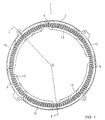
- FIG. 1 is a front view with the parts of the outer stator 1 omitted, a cross-sectional view is shown in FIG. 2, and an expanded view is shown in FIG. 3.
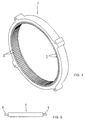
- a stator core 2 of an outer stator 1 forms a flat cylinder, as shown in FIG. 4, with a plurality of slots 3 formed in a circumferential direction being formed at the inner surface of the stator core 2 so as to point in an axial direction.
- the cross-sectional shape of one slot 3 is substantially rectangular (with rounded corners) and long in a radial direction.
- the slot 3 is long in the direction of the diameter and is narrow widthwise in the circumferential direction while maintaining a prescribed cross-sectional surface area. A large number of slots 3 of a prescribed cross-sectional surface area can therefore be formed within a fixed length of the inner periphery of the stator core 2.
- Bus bars 5 constituted by straight conductors are then inserted one at a time into each slot 3 of this fixed stator 2.
- the cross-sections of the bus bars 5 to be inserted into the slots 3 are substantially the same rectangular shape (specifically, elliptical in shape) as the cross-sections of the slots 3, have a prescribed length longer than the width of the stator core 2 in the axial direction, and have columnar projections 6 projecting from the center of both end surfaces thereof.
- the bus bars 5 are made of aluminum.
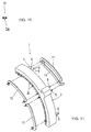
- a first joint plate 11 shown in FIG. 7 is an aluminum plate that is arc-shaped when viewed from the side with both ends bent inwards in the circumferential direction so as to form a C-shape.
- Circular holes 11a and 11a are formed at the bent end parts at both ends.
- a second joint plate 12 is a short aluminum plate (refer to FIG. 8) slightly shorter than the arc portion of the first joint plate 11, with identical circular holes 12a and 12a provided at the bent ends 12a and 12a.
- a third joint plate 12 is an aluminum plate which is generally arc shaped when viewed from the side as shown in FIG. 9 with both ends being bent inwards in a circumferential direction so as to form a C-shape, with holes 13a and 13a provided at both bent ends.
- the distances between circular holes 13a and 13a of the third joint plate 13 and between the circular holes 12a and 12a of the first joint plate 11 are equal.
- the circular hole 13a has a tapered section where the diameter of the hole is made broader towards one surface of the circular hole 13a.
- the circular holes 11a and 12a of the first and second joint plates 11 and 12 also have these tapered sections.
- the outer stator 1 is assembled from the stator core 2, the plurality of bus bars 5 and the first, second and third joint plates 11, 12 and 13.
- FIG. 11 A partially assembled state is shown in FIG. 11.
- Bus bars 5 are inserted into the slots 3 of the stator core 2 and projections 6 and 6 of two prescribed bus bars 5 and 5 pass through the circular holes 12a and 12a of a second joint plate 12 arranged along one side of the stator core 2 (the side on this side of the axial direction in FIG. 11).
- the ends of the projections 6 and 6 are then crushed so as to provide a calked coupling.
- the first joint plate 12 and the third joint plate 13 provided along the other side of the stator core 2 are also coupled in a riveted manner to projections 6 and 6 of two prescribed bus bars 5 and 5 in the same manner.
- the first, second and third joint plates 11, 12 and 13 are arranged so that the tapered sections of the circular holes 11a, 12a and 13a are on the opposite side (outer side) to the stator core 2.
- the tips of the projections 6 of the bus bars 5 that pass through the circular holes 11a, 12a and 13a are then crushed using a press so as to spread out into the tapered sections and provide calked coupling (refer to FIG. 2).
- FIG. 12 shows a continuous coupling structure for a single phase armature circuit with the stator core 2 omitted.
- a bus bar 5 1 and a bus bar 5 2 fifteen slots around to the right from the bus bar 5 1 are connected by the first joint plate 11 on the rear side.
- the bus bar 5 2 and a bus bar 5 3 thirteen slots back around to the left are coupled by the second joint plate 12 at the front side.
- the bus bar 5 3 and a bus bar 5 4 fifteen slots around to the right are coupled by a third joint plate 13 to the rear side.
- the bus bar 5 4 and a bus bar 5 5 thirteen slots around to the right are coupled at the front side by a second joint plate 12.
- the above coupling cycle is then repeated for three and a half cycles until just before a complete cycle is made.
- Neighboring bus bars 5 1 and 5 2 , and 5 2 and 5 4 etc. are structured so that current flows in the same direction in neighboring bus bars.
- This continuous bus bar continuously coupled structure and another type of bus bar continuously coupled structure are shifted with respect to each other in a slotwise direction so as to constitute a single-phase armature circuit, with a further two phases also being provided shifted in a slotwise direction to altogether give a three-phase armature circuit.
- the second joint plate 12 is overlaid at the front surface of the stator core 2 with insulating paper sandwiched therebetween, and the first joint plate 11 and third joint plate 13 are provided at the rear surface of the stator core 2 with insulating paper sandwiched therebetween.
- the rivet coupling circular holes 13a and 13a of the third joint plate 13 arranged at the rear surface of the stator core 2 are, at bent end sections, bent outwards away from the center of the stator core 2 and the main body therefore projects slightly inwards towards the center of the stator core 2 (refer to FIG. 1 and FIG. 2).
- the inner rotor can therefore be inserted from the front surface of the stator core 2 without being hindered by the third joint plate 13, i.e. it is inserted in the direction of the arrow of FIG. 2.
- one bus bar 5 is inserted into one slot 3 of the stator core 2 and the cross-section of the bus bar substantially coincides with the cross-section of the slot 3.
- the capacity within the slot is therefore utilized in an effective manner and the space factor of the conductor is maximized.
- the slots 3 are substantially rectangular so as to be long in the direction of the diameter of the fixed core 2 and a large number of slots 3 can be formed at the inner peripheral surface of the stator core 2, so that a large number of bus bars 5 can be inserted.
- the ends of the bus bars 5 engage with the joint plates in a vertical manner and there is therefore no need to bend the bus bars themselves. It is therefore easy to maintain the cross-sectional area of the bus bar 5 taken as a conductor and a large space factor can be maintained within the slot 3.
- the bus bars 5 and the first, second and third joint plates 11, 12 and 13 are made of aluminum and are therefore lightweight and cheap.
- the number of types of members for coupling the bus bars 5 is low at the three types of the first, second and third joint plates 11, 12 and 13, the bus bars 5 are directly inserted into the slots 3 in a straightforward manner, and the coupling of the first, second and third joint plates 11, 12 and 13 is achieved by riveting, which makes the work involved in assembly easy.
- the outer stator is also compact because the plate-shaped first, second and third joint plates 11, 12 and 13 are laid onto the sides of the stator core 2.
- FIG. 13 An example of a different shape for the slots in the stator core is shown in FIG. 13.
- a slot 21 of a stator core 20 has a cross-section that is trapezoidal in shape and long in the direction of the diameter of the stator core 20, with an outer short side being larger than an inner short side of the trapezoid.
- An aluminum bus bar 22 of a trapezoidal cross-sectional shape that is the same as the trapezoidal cross-sectional shape of the slot 21 is then inserted into the slot 21.
- Prescribed pairs of bus bars 22 and 22 are then coupled in the same manner using the joint plates.
- a small-type motor where the cross-sectional area of the bus bar 22 taken as a conductor can easily be maintained, a large space factor can be maintained within the slot 21, ohmic loss can be reduced and cooling is superior can therefore be provided.
- a stator core 30 has slots 31 rectangular in cross-section and being long in the direction of the diameter of the stator core 30, with three bus bars 32, each being rectangular in cross-section, being inserted into each of the slots 31.
- the three bus bars 32 are aluminum and together have a cross-section substantially equal to the cross-section of the rectangular shape of the slot 31, the slot 31 is substantially filled up and the space factor is therefore high.
- the outer stator is applied to a d.c. brushless motor, but can also be applied to use in a synchronous motor and other types of motor.
- the invention provides a small-type motor where the assembly of conductors into slots is straightforward, the space factor for the conductors within the slot is high, ohmic loss is reduced and cooling is superior.
- a motor stator structure where a plurality of slots 3 are formed pointing in an axial direction at the inner peripheral surface of a cylindrical stator core 2 and conductors 5 of substantially the same cross-sectional shape as the slots 3 are inserted into the slots 3.
Abstract
Description
- The present invention relates to a structure for an outer stator of an inner rotor-type motor.
- A plurality of slots are formed in a circumferential direction so as to point along the axial direction at the inner surface of a stator core formed in the shape of a cylinder for this type of motor, with a plurality of stator windings being inserted into one slot.
- Inserting of the plurality of stator windings in line with the cross-sectional shape of the slots is not straightforward and gaps occur between the windings and the inner surfaces of the slots because windings with circular cross-sections are inserted, which it would be preferable to avoid.
- This puts limits on the space factor of a conductor within a slot, ohmic loss due to the splitting up of the volume of the slots is substantial and cooling is poor.
- In order to resolve the above points, it is the object of the present invention to provide a small motor where assembly of the conductor into the slot is straightforward, the space factor of the conductor within the slot is increased and ohmic loss is reduced.
- In order to achieve the aforementioned, in a motor stator structure where a plurality of slots pointing in an axial direction are formed at an inner peripheral surface of a cylindrical stator core, conductors of substantially the same cross-sectional shape as the slots are inserted into the slots.
- A small-type motor where the capacity of the slots is effectively utilized, the space factor of the conductors is raised up to close to 100%, ohmic loss is reduced and cooling is superior can therefore be provided because the cross-sectional shape of the slots and the conductors is substantially equal (including the case where the cross-sectional shapes are the same).
- In the aspect of
claim 2, one conductor is inserted into each slot of the motor stator structure ofclaim 1. - Because one conductor is inserted into one slot, there are no gaps etc. between windings that accompany the insertion of a plurality of windings, the capacity of the slots is effectively utilized and the space factor of the conductor is increased.
- In the aspect of
claim 3, in the motor stator structure ofclaim 1, the slots of the stator core are rectangular and long in a radial direction. - A large number of slots can therefore be formed at the inner surface of the stator core, the number of conductors can be increased and motor performance can therefore be improved.
- In the aspect of claim 4, in motor stator structure of
claim 1 orclaim 2, the conductors are straight bus bars, and joint plates that are arc-shaped when viewed from the side are arranged along the side surfaces of the stator core, with ends of the joint plates being coupled in such a manner as to become riveted to the ends of predetermined pairs of bus bars so as to form a circuit. - The bus bars are straight, which makes assembly into the slots of the stator core straightforward.
- It is not necessary to bend the ends of the bus bar for coupling because joint plates for coupling prescribed pairs of bus bars are used for this purpose and there is therefore no inconvenience even when the cross-sectional area of the bus bars is made sufficiently large. Accordingly, a substantial space factor can be maintained for conductors within the slots of the stator core.
- The joint plates are arc-shaped when viewed from the side and are therefore arranged on substantially concentric circles at the annular-shaped side surface of the stator core so as to be flat, and the stator is therefore compact.
- The joint plate and bus bars are coupled in a riveted manner, which makes assembly straightforward and conductivity high.
- In the aspect of
claim 5, in motor stator structure of claim 4, long and short first and second joint plates where the ends of the arc-shaped joint plates are bent radially inwards in a deformed C-shape and a third joint plate with ends bent outwards in the circumferential direction in a deformed C-shape are arranged on the side surfaces of the stator core in prescribed numbers. - The entire stator circuit can be constructed by coupling pairs of conductors using the three types of joint plate of the first, second and third joint plates. There are therefore few parts and assembly is straightforward.
- The number of joint plates that are overlaid can be made small and the stator can be made compact because long and short first and second joint plates with ends bent radially inwards in a deformed C-shape and a third joint plate with ends bent radially outwards in a deformed C-shape can be combined on the same surface.
- The following is a description of the embodiments of the present invention shown in FIG. 1 to FIG. 12.
- FIG. 1 is a front view of the outer stator of a d.c. brushless motor of an embodiment of the present invention;
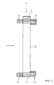
- FIG. 2 is a cross-section taken along line II-O-II of FIG. 1;
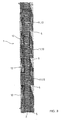
- FIG. 3 is an expanded view of the same outer stator;
- FIG. 4 is a perspective view of a stator core;
- FIG. 5 is a side view of a bus bar;
- FIG. 6 is a front view of the same;
- FIG. 7 is a side view of the first joint plate;
- FIG. 8 is a side view of the second joint plate;
- FIG. 9 is a side view of the third joint plate;
- FIG. 10 is a cross-sectional view taken along line X-X of FIG. 9;
- FIG. 11 is a partial perspective view showing a situation when assembling bus bars and joint plates at the stator core;
- FIG. 12 is a perspective view showing part of a coupling structure for an armature circuit;
- FIG. 13 is a partial cross-section of a stator of a further embodiment; and
- FIG. 14 is a partial cross-section of a stator of a still further embodiment.
-
- The motor of this embodiment is a d.c. brushless motor where an
outer motor 1 comprised of a three-phase armature circuit is assembled at the outer periphery of an inner rotor that forms a field using a permanent magnet. - FIG. 1 is a front view with the parts of the
outer stator 1 omitted, a cross-sectional view is shown in FIG. 2, and an expanded view is shown in FIG. 3. - A
stator core 2 of anouter stator 1 forms a flat cylinder, as shown in FIG. 4, with a plurality ofslots 3 formed in a circumferential direction being formed at the inner surface of thestator core 2 so as to point in an axial direction. - The cross-sectional shape of one
slot 3 is substantially rectangular (with rounded corners) and long in a radial direction. - The
slot 3 is long in the direction of the diameter and is narrow widthwise in the circumferential direction while maintaining a prescribed cross-sectional surface area. A large number ofslots 3 of a prescribed cross-sectional surface area can therefore be formed within a fixed length of the inner periphery of thestator core 2. -
Bus bars 5 constituted by straight conductors are then inserted one at a time into eachslot 3 of thisfixed stator 2. - Referring to FIG. 5 and FIG. 6, the cross-sections of the
bus bars 5 to be inserted into theslots 3 are substantially the same rectangular shape (specifically, elliptical in shape) as the cross-sections of theslots 3, have a prescribed length longer than the width of thestator core 2 in the axial direction, and havecolumnar projections 6 projecting from the center of both end surfaces thereof. - The
bus bars 5 are made of aluminum. - Joint plates linking the
projections 6 of thebus bars 5 couple fellow bus bars together. - Three types of joint plates are used. A first
joint plate 11 shown in FIG. 7 is an aluminum plate that is arc-shaped when viewed from the side with both ends bent inwards in the circumferential direction so as to form a C-shape. -
Circular holes - A
second joint plate 12 is a short aluminum plate (refer to FIG. 8) slightly shorter than the arc portion of thefirst joint plate 11, with identicalcircular holes bent ends - A
third joint plate 12 is an aluminum plate which is generally arc shaped when viewed from the side as shown in FIG. 9 with both ends being bent inwards in a circumferential direction so as to form a C-shape, withholes - The distances between
circular holes third joint plate 13 and between thecircular holes first joint plate 11 are equal. - Looking at the cross-section of the
circular hole 13a, thecircular hole 13a has a tapered section where the diameter of the hole is made broader towards one surface of thecircular hole 13a. - The
circular holes second joint plates - The
outer stator 1 is assembled from thestator core 2, the plurality ofbus bars 5 and the first, second andthird joint plates - A partially assembled state is shown in FIG. 11.
Bus bars 5 are inserted into theslots 3 of thestator core 2 andprojections bus bars circular holes second joint plate 12 arranged along one side of the stator core 2 (the side on this side of the axial direction in FIG. 11). The ends of theprojections joint plate 12 and thethird joint plate 13 provided along the other side of thestator core 2 are also coupled in a riveted manner toprojections bus bars - The first, second and
third joint plates circular holes stator core 2. The tips of theprojections 6 of thebus bars 5 that pass through thecircular holes - The work involved in this coupling is therefore straightforward and the surface of the joint plate can be kept flat because the riveted portions of the
projections 6 spread out into the tapered sections and therefore do not project from the surfaces of the joint plates. - FIG. 12 shows a continuous coupling structure for a single phase armature circuit with the
stator core 2 omitted. - Taking this side in the axial direction in FIG. 12 as the front side (the front surface of the fixed stator 2) and the back side as the rear side (the rear surface of the stator core 2), a
bus bar 51 and abus bar 52 fifteen slots around to the right from thebus bar 51 are connected by the firstjoint plate 11 on the rear side. Thebus bar 52 and abus bar 53 thirteen slots back around to the left are coupled by the secondjoint plate 12 at the front side. Thebus bar 53 and abus bar 54 fifteen slots around to the right are coupled by a thirdjoint plate 13 to the rear side. Thebus bar 54 and abus bar 55 thirteen slots around to the right are coupled at the front side by a secondjoint plate 12. The above coupling cycle is then repeated for three and a half cycles until just before a complete cycle is made. - Neighboring
bus bars - This continuous bus bar continuously coupled structure and another type of bus bar continuously coupled structure are shifted with respect to each other in a slotwise direction so as to constitute a single-phase armature circuit, with a further two phases also being provided shifted in a slotwise direction to altogether give a three-phase armature circuit.
- As shown in FIG. 2 and FIG. 3, the second
joint plate 12 is overlaid at the front surface of thestator core 2 with insulating paper sandwiched therebetween, and the firstjoint plate 11 and thirdjoint plate 13 are provided at the rear surface of thestator core 2 with insulating paper sandwiched therebetween. - The rivet coupling
circular holes joint plate 13 arranged at the rear surface of thestator core 2 are, at bent end sections, bent outwards away from the center of thestator core 2 and the main body therefore projects slightly inwards towards the center of the stator core 2 (refer to FIG. 1 and FIG. 2). - The inner rotor can therefore be inserted from the front surface of the
stator core 2 without being hindered by the thirdjoint plate 13, i.e. it is inserted in the direction of the arrow of FIG. 2. - Regarding the
outer stator 1 of this d.c. brushless motor, onebus bar 5 is inserted into oneslot 3 of thestator core 2 and the cross-section of the bus bar substantially coincides with the cross-section of theslot 3. The capacity within the slot is therefore utilized in an effective manner and the space factor of the conductor is maximized. - Further, the
slots 3 are substantially rectangular so as to be long in the direction of the diameter of the fixedcore 2 and a large number ofslots 3 can be formed at the inner peripheral surface of thestator core 2, so that a large number ofbus bars 5 can be inserted. - The ends of the
bus bars 5 engage with the joint plates in a vertical manner and there is therefore no need to bend the bus bars themselves. It is therefore easy to maintain the cross-sectional area of thebus bar 5 taken as a conductor and a large space factor can be maintained within theslot 3. - According to the above configuration, current flows effectively in the armature conductor of the
bus bar 5, ohmic loss is reduced, superior cooling can be maintained and miniaturization can be achieved. - The bus bars 5 and the first, second and third
joint plates - The number of types of members for coupling the bus bars 5 is low at the three types of the first, second and third
joint plates slots 3 in a straightforward manner, and the coupling of the first, second and thirdjoint plates - The outer stator is also compact because the plate-shaped first, second and third
joint plates stator core 2. - An example of a different shape for the slots in the stator core is shown in FIG. 13.
- A
slot 21 of astator core 20 has a cross-section that is trapezoidal in shape and long in the direction of the diameter of thestator core 20, with an outer short side being larger than an inner short side of the trapezoid. - An
aluminum bus bar 22 of a trapezoidal cross-sectional shape that is the same as the trapezoidal cross-sectional shape of theslot 21 is then inserted into theslot 21. - Prescribed pairs of
bus bars - A small-type motor where the cross-sectional area of the
bus bar 22 taken as a conductor can easily be maintained, a large space factor can be maintained within theslot 21, ohmic loss can be reduced and cooling is superior can therefore be provided. - A description is now given based on FIG. 14 of a further embodiment.
- A
stator core 30 hasslots 31 rectangular in cross-section and being long in the direction of the diameter of thestator core 30, with threebus bars 32, each being rectangular in cross-section, being inserted into each of theslots 31. - The three
bus bars 32 are aluminum and together have a cross-section substantially equal to the cross-section of the rectangular shape of theslot 31, theslot 31 is substantially filled up and the space factor is therefore high. - Examples of various modifications to the cross-sectional shape of the slots can be considered.
- Further, the insertion of two or four or more conductors into a slot can also be considered.
- In the above, the outer stator is applied to a d.c. brushless motor, but can also be applied to use in a synchronous motor and other types of motor.
The invention provides a small-type motor where the assembly of conductors into slots is straightforward, the space factor for the conductors within the slot is high, ohmic loss is reduced and cooling is superior. - To achieve this, a motor stator structure where a plurality of
slots 3 are formed pointing in an axial direction at the inner peripheral surface of acylindrical stator core 2 andconductors 5 of substantially the same cross-sectional shape as theslots 3 are inserted into theslots 3.
Claims (5)
- A motor stator structure with a plurality of slots (3) pointing in an axial direction formed at an inner peripheral surface of a cylindrical stator core (2), wherein conductors (5) of substantially the same cross-sectional shape as the slots (3) are inserted into the slots (3).
- The motor stator structure of claim 1, wherein one conductor (5) is inserted into each slot.
- The motor stator structure of claim 1, wherein the slots (3) of the stator core (2) are rectangular and long in a radial direction.
- The motor stator structure of claim 1 or claim 2, wherein the conductors are straight bus bars (5;22;32), andjoint plates (11,12,13) that are arc-shaped when viewed from the side are arranged along the side surfaces of the stator core (2,20), with ends of the joint plates being coupled in such a manner as to become riveted to the ends of predetermined pairs of bus bars (5;22;32) so as to form a circuit.
- The motor stator structure of claim 4, wherein long and short first and second joint plates (11,12) where the ends of the arc-shaped joint plates are bent radially inwards in a deformed C-shape and a third joint plate (13) with ends bent outwards in the circumferential direction in a deformed C-shape are arranged on the side surfaces of the stator core (2) in prescribed numbers.
Applications Claiming Priority (2)
| Application Number | Priority Date | Filing Date | Title |
|---|---|---|---|
| JP7558399 | 1999-03-19 | ||
| JP11075583A JP2000270506A (en) | 1999-03-19 | 1999-03-19 | Stator structure for motor |
Publications (3)
| Publication Number | Publication Date |
|---|---|
| EP1039616A2 true EP1039616A2 (en) | 2000-09-27 |
| EP1039616A3 EP1039616A3 (en) | 2001-07-18 |
| EP1039616B1 EP1039616B1 (en) | 2004-01-02 |
Family
ID=13580370
Family Applications (1)
| Application Number | Title | Priority Date | Filing Date |
|---|---|---|---|
| EP00102864A Expired - Lifetime EP1039616B1 (en) | 1999-03-19 | 2000-02-11 | Motor stator structure |
Country Status (4)
| Country | Link |
|---|---|
| US (1) | US6252327B1 (en) |
| EP (1) | EP1039616B1 (en) |
| JP (1) | JP2000270506A (en) |
| DE (1) | DE60007474T2 (en) |
Cited By (12)
| Publication number | Priority date | Publication date | Assignee | Title |
|---|---|---|---|---|
| WO2002045241A1 (en) * | 2000-11-30 | 2002-06-06 | Compact Dynamics Gmbh | Stator for an electric machine and method for producing the same |
| DE10124946A1 (en) * | 2001-05-21 | 2002-12-05 | Reiner Binder | Armature winding and process for its manufacture |
| DE10143217C1 (en) * | 2001-09-04 | 2003-02-27 | Compact Dynamics Gmbh | Traveling wave machine |
| WO2004047253A1 (en) * | 2002-11-15 | 2004-06-03 | In Motion Technologies Pty Ltd | Poly-phase electromagnetic device having an improved conductor winding arrangement |
| DE10312441A1 (en) * | 2003-03-20 | 2004-10-07 | Compact Dynamics Gmbh | Traveling wave machine |
| WO2005004308A1 (en) | 2003-07-01 | 2005-01-13 | Compact Dynamics Gmbh | Travelling field machine |
| DE102007021737A1 (en) | 2007-05-09 | 2008-11-20 | Compact Dynamics Gmbh | Traveling wave machine |
| WO2017186644A1 (en) * | 2016-04-28 | 2017-11-02 | Wobben Properties Gmbh | Coil and winding structure, and stator for a generator of a wind turbine, and method for producing a stator |
| WO2018206324A1 (en) * | 2017-05-10 | 2018-11-15 | Continental Automotive Gmbh | Stator for an electric machine and electric machine |
| WO2019110057A1 (en) * | 2017-12-07 | 2019-06-13 | Aumann AG | Method for producing an arrangement for a plug-in coil of an electrical machine, and arrangement |
| DE10154582B4 (en) * | 2000-11-09 | 2020-09-03 | Mitsubishi Denki K.K. | Stator of a rotating electrical machine |
| FR3113210A1 (en) * | 2020-07-28 | 2022-02-04 | Universite De Montpellier | Connection bridge for making a bun on a stator of a rotating electrical machine. |
Families Citing this family (21)
| Publication number | Priority date | Publication date | Assignee | Title |
|---|---|---|---|---|
| US6548933B2 (en) * | 2000-01-31 | 2003-04-15 | Hitachi, Ltd. | Stator of rotating electric machine |
| US6459189B1 (en) * | 2000-05-08 | 2002-10-01 | Emerson Electric Co. | Diecast rotor with compound short-circuit loops and method of manufacture |
| US6774530B2 (en) * | 2002-06-07 | 2004-08-10 | Briggs & Stratton Corporation | Winding assemblies for electrical machines |
| US7583063B2 (en) | 2003-05-27 | 2009-09-01 | Pratt & Whitney Canada Corp. | Architecture for electric machine |
| US6965183B2 (en) * | 2003-05-27 | 2005-11-15 | Pratt & Whitney Canada Corp. | Architecture for electric machine |
| JP2005160143A (en) * | 2003-11-20 | 2005-06-16 | Toyota Motor Corp | Stator for dynamo-electric machine |
| US6958561B2 (en) * | 2004-02-27 | 2005-10-25 | Unique Product & Design Co., Ltd. | Stator winding structure of a motor or a generator |
| KR100973686B1 (en) * | 2008-06-23 | 2010-08-03 | 전자부품연구원 | Stator of coreless motor |
| US20100038988A1 (en) * | 2008-08-12 | 2010-02-18 | Gannon Ramy | Stator and Method of Making the Same |
| US8736127B2 (en) * | 2011-02-17 | 2014-05-27 | Innerpoint Energy Corporation | Dynamoelectric device and method of forming the same |
| ES2819190T3 (en) * | 2011-02-28 | 2021-04-15 | Flender Gmbh | Electric machine, in particular an electric generator |
| US9018822B2 (en) * | 2011-03-08 | 2015-04-28 | Honda Motor Co., Ltd. | Stator for rotary electric machine |
| JP5389109B2 (en) | 2011-07-21 | 2014-01-15 | 本田技研工業株式会社 | Rotating electric machine stator |
| JP6775909B2 (en) * | 2014-01-27 | 2020-10-28 | 三菱電機株式会社 | Rotating machine |
| US10431364B2 (en) | 2014-02-27 | 2019-10-01 | C&C Technologies, Llc | Electro-mechanical device and manufacturing methods for various applications |
| WO2015151200A1 (en) | 2014-03-31 | 2015-10-08 | 本田技研工業株式会社 | Stator for rotary electric machine |
| JP6598736B2 (en) * | 2016-06-10 | 2019-10-30 | 三菱電機株式会社 | Rotating electric machine stator |
| DE102016123069A1 (en) | 2016-11-30 | 2018-05-30 | Dr. Ing. H.C. F. Porsche Aktiengesellschaft | Method and device for producing a conductor segment |
| DE102016123068A1 (en) | 2016-11-30 | 2018-05-30 | Dr. Ing. H.C. F. Porsche Aktiengesellschaft | Rotary electric machine and specially adapted method for producing such |
| CN109586464B (en) * | 2017-09-29 | 2021-11-12 | 比亚迪股份有限公司 | Stator module, motor and vehicle |
| DE102018125836A1 (en) * | 2018-10-18 | 2020-04-23 | Dr. Ing. H.C. F. Porsche Aktiengesellschaft | Stator for an electrical machine |
Citations (6)
| Publication number | Priority date | Publication date | Assignee | Title |
|---|---|---|---|---|
| US1512693A (en) * | 1922-10-18 | 1924-10-21 | H Cuenod Sa Atel | Induction motor |
| US1784815A (en) * | 1928-06-14 | 1930-12-16 | Vincent G Apple | Dynamo-electric-machine element |
| US4115915A (en) * | 1975-07-31 | 1978-09-26 | General Electric Company | Process for manufacturing motor having windings constructed for automated assembly |
| US4321497A (en) * | 1980-04-10 | 1982-03-23 | Westinghouse Electric Corp. | Peripheral connector ring stator end winding for dynamoelectric machines |
| JPH09215238A (en) * | 1996-01-30 | 1997-08-15 | Hitachi Ltd | Rotating machine and its forming method |
| EP0899850A1 (en) * | 1993-10-15 | 1999-03-03 | Denso Corporation | Electric rotating machine |
Family Cites Families (3)
| Publication number | Priority date | Publication date | Assignee | Title |
|---|---|---|---|---|
| US2407935A (en) * | 1944-05-25 | 1946-09-17 | Chrysler Corp | Electrical machine |
| US4309634A (en) * | 1980-04-10 | 1982-01-05 | Westinghouse Electric Corp. | Stator winding peripheral connector rings |
| JP2827773B2 (en) * | 1992-12-21 | 1998-11-25 | 株式会社日立製作所 | Method of forming rotating armature and armature winding |
-
1999
- 1999-03-19 JP JP11075583A patent/JP2000270506A/en active Pending
-
2000
- 2000-02-11 DE DE60007474T patent/DE60007474T2/en not_active Expired - Fee Related
- 2000-02-11 EP EP00102864A patent/EP1039616B1/en not_active Expired - Lifetime
- 2000-03-17 US US09/527,265 patent/US6252327B1/en not_active Expired - Fee Related
Patent Citations (6)
| Publication number | Priority date | Publication date | Assignee | Title |
|---|---|---|---|---|
| US1512693A (en) * | 1922-10-18 | 1924-10-21 | H Cuenod Sa Atel | Induction motor |
| US1784815A (en) * | 1928-06-14 | 1930-12-16 | Vincent G Apple | Dynamo-electric-machine element |
| US4115915A (en) * | 1975-07-31 | 1978-09-26 | General Electric Company | Process for manufacturing motor having windings constructed for automated assembly |
| US4321497A (en) * | 1980-04-10 | 1982-03-23 | Westinghouse Electric Corp. | Peripheral connector ring stator end winding for dynamoelectric machines |
| EP0899850A1 (en) * | 1993-10-15 | 1999-03-03 | Denso Corporation | Electric rotating machine |
| JPH09215238A (en) * | 1996-01-30 | 1997-08-15 | Hitachi Ltd | Rotating machine and its forming method |
Non-Patent Citations (1)
| Title |
|---|
| PATENT ABSTRACTS OF JAPAN vol. 1997, no. 12, 25 December 1997 (1997-12-25) & JP 09 215238 A (HITACHI LTD), 15 August 1997 (1997-08-15) * |
Cited By (25)
| Publication number | Priority date | Publication date | Assignee | Title |
|---|---|---|---|---|
| DE10154582B4 (en) * | 2000-11-09 | 2020-09-03 | Mitsubishi Denki K.K. | Stator of a rotating electrical machine |
| WO2002045241A1 (en) * | 2000-11-30 | 2002-06-06 | Compact Dynamics Gmbh | Stator for an electric machine and method for producing the same |
| DE10059575A1 (en) * | 2000-11-30 | 2002-07-11 | Compact Dynamics Gmbh | Electrical machine and stator for an electrical machine and manufacturing method therefor |
| DE10059575C2 (en) * | 2000-11-30 | 2002-11-07 | Compact Dynamics Gmbh | Electrical machine and stator for an electrical machine and manufacturing method therefor |
| DE10124946A1 (en) * | 2001-05-21 | 2002-12-05 | Reiner Binder | Armature winding and process for its manufacture |
| DE10143217C1 (en) * | 2001-09-04 | 2003-02-27 | Compact Dynamics Gmbh | Traveling wave machine |
| WO2004047253A1 (en) * | 2002-11-15 | 2004-06-03 | In Motion Technologies Pty Ltd | Poly-phase electromagnetic device having an improved conductor winding arrangement |
| US7521834B2 (en) | 2002-11-15 | 2009-04-21 | Dean James Patterson | Poly-phase electromagnetic device having an improved conductor winding arrangement |
| CN100407551C (en) * | 2002-11-15 | 2008-07-30 | 运动先锋科技公司 | Poly-phase electromagnetic device having an improved conductor winding arrangement |
| DE10312441A1 (en) * | 2003-03-20 | 2004-10-07 | Compact Dynamics Gmbh | Traveling wave machine |
| DE10312441B4 (en) * | 2003-03-20 | 2009-02-26 | Compact Dynamics Gmbh | Traveling wave machine |
| US7476997B2 (en) | 2003-07-01 | 2009-01-13 | Compact Dynamics Gmbh | Travelling field machine |
| WO2005004308A1 (en) | 2003-07-01 | 2005-01-13 | Compact Dynamics Gmbh | Travelling field machine |
| DE10329641A1 (en) * | 2003-07-01 | 2005-02-03 | Compact Dynamics Gmbh | Traveling wave machine |
| DE102007021737A1 (en) | 2007-05-09 | 2008-11-20 | Compact Dynamics Gmbh | Traveling wave machine |
| WO2008138488A3 (en) * | 2007-05-09 | 2009-02-19 | Compact Dynamics Gmbh | Linear machine |
| WO2008138488A2 (en) * | 2007-05-09 | 2008-11-20 | Compact Dynamics Gmbh | Linear machine |
| WO2017186644A1 (en) * | 2016-04-28 | 2017-11-02 | Wobben Properties Gmbh | Coil and winding structure, and stator for a generator of a wind turbine, and method for producing a stator |
| CN109075625A (en) * | 2016-04-28 | 2018-12-21 | 乌本产权有限公司 | The coil and winding construction and stator of the generator of wind energy plant and method for manufacturing stator |
| RU2714702C1 (en) * | 2016-04-28 | 2020-02-19 | Воббен Пропертиз Гмбх | Winding and winding device, as well for stator of generator of wind-driven power plant and stator manufacturing method |
| US11095176B2 (en) | 2016-04-28 | 2021-08-17 | Wobben Properties Gmbh | Aluminum form-wound coil and winding structure, and stator for a generator of a wind turbine, and method for producing a stator |
| WO2018206324A1 (en) * | 2017-05-10 | 2018-11-15 | Continental Automotive Gmbh | Stator for an electric machine and electric machine |
| WO2019110057A1 (en) * | 2017-12-07 | 2019-06-13 | Aumann AG | Method for producing an arrangement for a plug-in coil of an electrical machine, and arrangement |
| US11705790B2 (en) * | 2017-12-07 | 2023-07-18 | Aumann AG | Method for producing an arrangement for a plug-in coil of an electrical machine, and arrangement |
| FR3113210A1 (en) * | 2020-07-28 | 2022-02-04 | Universite De Montpellier | Connection bridge for making a bun on a stator of a rotating electrical machine. |
Also Published As
| Publication number | Publication date |
|---|---|
| US6252327B1 (en) | 2001-06-26 |
| EP1039616A3 (en) | 2001-07-18 |
| EP1039616B1 (en) | 2004-01-02 |
| JP2000270506A (en) | 2000-09-29 |
| DE60007474T2 (en) | 2004-07-08 |
| DE60007474D1 (en) | 2004-02-05 |
Similar Documents
| Publication | Publication Date | Title |
|---|---|---|
| EP1039616B1 (en) | Motor stator structure | |
| JP5389109B2 (en) | Rotating electric machine stator | |
| JP6196928B2 (en) | Rotating electric machine stator | |
| JP3881757B2 (en) | Connection terminal for stator | |
| JP5395130B2 (en) | Manufacturing method of stator of rotating electric machine | |
| JP6364465B2 (en) | Slot coil and stator of rotating electric machine | |
| WO2015151200A1 (en) | Stator for rotary electric machine | |
| WO1990004874A1 (en) | Laminated stators for dynamo-electric machines | |
| JP4344695B2 (en) | Stator for outer rotor type multipolar generator and its assembling method | |
| JP5745358B2 (en) | Rotating electric machine stator | |
| JP2003219591A (en) | Dynamo electric machine | |
| JP2004166494A (en) | Stator tube and its production method for internal rotor dc motor | |
| JP2000209793A (en) | Stator for rotary electric machine | |
| JP5389108B2 (en) | Stator for rotating electrical machine and method for manufacturing the same | |
| JP6322665B2 (en) | Slot coil and stator of rotating electric machine | |
| JP6141802B2 (en) | Rotating electric machine stator | |
| JP6140632B2 (en) | Rotating electric machine stator | |
| CN110768431B (en) | Stator for motor, permanent magnet motor with same and compressor | |
| JP6397851B2 (en) | Slot coil and stator of rotating electric machine | |
| CN112003410B (en) | Casing subassembly, casing, piecemeal stator assembly subassembly, stator assembly and motor | |
| JP2001136687A (en) | Permanent magnet rotary electric machine | |
| JP2018143060A (en) | Stator of rotary electric machine | |
| CN210297384U (en) | Insulating support and compressor stator | |
| JPH10201187A (en) | Coil assembling method of switched reluctance motor | |
| JP2000134853A (en) | Electric motor |
Legal Events
| Date | Code | Title | Description |
|---|---|---|---|
| PUAI | Public reference made under article 153(3) epc to a published international application that has entered the european phase |
Free format text: ORIGINAL CODE: 0009012 |
|
| AK | Designated contracting states |
Kind code of ref document: A2 Designated state(s): DE FR GB |
|
| AX | Request for extension of the european patent |
Free format text: AL;LT;LV;MK;RO;SI |
|
| PUAL | Search report despatched |
Free format text: ORIGINAL CODE: 0009013 |
|
| AK | Designated contracting states |
Kind code of ref document: A3 Designated state(s): AT BE CH CY DE DK ES FI FR GB GR IE IT LI LU MC NL PT SE |
|
| AX | Request for extension of the european patent |
Free format text: AL;LT;LV;MK;RO;SI |
|
| 17P | Request for examination filed |
Effective date: 20011126 |
|
| AKX | Designation fees paid |
Free format text: DE FR GB |
|
| 17Q | First examination report despatched |
Effective date: 20020708 |
|
| GRAP | Despatch of communication of intention to grant a patent |
Free format text: ORIGINAL CODE: EPIDOSNIGR1 |
|
| GRAS | Grant fee paid |
Free format text: ORIGINAL CODE: EPIDOSNIGR3 |
|
| GRAA | (expected) grant |
Free format text: ORIGINAL CODE: 0009210 |
|
| AK | Designated contracting states |
Kind code of ref document: B1 Designated state(s): DE FR GB |
|
| REG | Reference to a national code |
Ref country code: GB Ref legal event code: FG4D |
|
| REF | Corresponds to: |
Ref document number: 60007474 Country of ref document: DE Date of ref document: 20040205 Kind code of ref document: P |
|
| ET | Fr: translation filed | ||
| PLBE | No opposition filed within time limit |
Free format text: ORIGINAL CODE: 0009261 |
|
| STAA | Information on the status of an ep patent application or granted ep patent |
Free format text: STATUS: NO OPPOSITION FILED WITHIN TIME LIMIT |
|
| 26N | No opposition filed |
Effective date: 20041005 |
|
| PGFP | Annual fee paid to national office [announced via postgrant information from national office to epo] |
Ref country code: FR Payment date: 20050223 Year of fee payment: 6 |
|
| REG | Reference to a national code |
Ref country code: FR Ref legal event code: ST Effective date: 20061031 |
|
| PGFP | Annual fee paid to national office [announced via postgrant information from national office to epo] |
Ref country code: GB Payment date: 20070207 Year of fee payment: 8 |
|
| PGFP | Annual fee paid to national office [announced via postgrant information from national office to epo] |
Ref country code: DE Payment date: 20070208 Year of fee payment: 8 |
|
| PG25 | Lapsed in a contracting state [announced via postgrant information from national office to epo] |
Ref country code: FR Free format text: LAPSE BECAUSE OF NON-PAYMENT OF DUE FEES Effective date: 20060228 |
|
| GBPC | Gb: european patent ceased through non-payment of renewal fee |
Effective date: 20080211 |
|
| PG25 | Lapsed in a contracting state [announced via postgrant information from national office to epo] |
Ref country code: DE Free format text: LAPSE BECAUSE OF NON-PAYMENT OF DUE FEES Effective date: 20080902 |
|
| PG25 | Lapsed in a contracting state [announced via postgrant information from national office to epo] |
Ref country code: GB Free format text: LAPSE BECAUSE OF NON-PAYMENT OF DUE FEES Effective date: 20080211 |