EP1033876A1 - Radio mobile terminal with a mountable and removable camera - Google Patents
Radio mobile terminal with a mountable and removable camera Download PDFInfo
- Publication number
- EP1033876A1 EP1033876A1 EP00103476A EP00103476A EP1033876A1 EP 1033876 A1 EP1033876 A1 EP 1033876A1 EP 00103476 A EP00103476 A EP 00103476A EP 00103476 A EP00103476 A EP 00103476A EP 1033876 A1 EP1033876 A1 EP 1033876A1
- Authority
- EP
- European Patent Office
- Prior art keywords
- destination terminal
- camera
- radio mobile
- videophone
- mobile terminal
- Prior art date
- Legal status (The legal status is an assumption and is not a legal conclusion. Google has not performed a legal analysis and makes no representation as to the accuracy of the status listed.)
- Granted
Links
Images


Classifications
-
- H—ELECTRICITY
- H04—ELECTRIC COMMUNICATION TECHNIQUE
- H04N—PICTORIAL COMMUNICATION, e.g. TELEVISION
- H04N7/00—Television systems
- H04N7/14—Systems for two-way working
- H04N7/141—Systems for two-way working between two video terminals, e.g. videophone
- H04N7/142—Constructional details of the terminal equipment, e.g. arrangements of the camera and the display
-
- H—ELECTRICITY
- H04—ELECTRIC COMMUNICATION TECHNIQUE
- H04N—PICTORIAL COMMUNICATION, e.g. TELEVISION
- H04N7/00—Television systems
- H04N7/14—Systems for two-way working
- H04N7/141—Systems for two-way working between two video terminals, e.g. videophone
- H04N7/148—Interfacing a video terminal to a particular transmission medium, e.g. ISDN
-
- H—ELECTRICITY
- H04—ELECTRIC COMMUNICATION TECHNIQUE
- H04N—PICTORIAL COMMUNICATION, e.g. TELEVISION
- H04N7/00—Television systems
- H04N7/14—Systems for two-way working
- H04N7/141—Systems for two-way working between two video terminals, e.g. videophone
- H04N7/142—Constructional details of the terminal equipment, e.g. arrangements of the camera and the display
- H04N2007/145—Handheld terminals
Definitions
- the present invention relates to a radio mobile terminal.
- Radio mobile terminals include a radio mobile videophone terminal that can send and receive motion pictures as well as voices by attaching a camera to a commercially available mobile telephone.
- This type of videophone terminals employs a configuration as shown in FIG. 8 for communicating data including voices and images with a remote terminal via a base station.
- a high-frequency signal received at an antenna 1 is supplied to a receiver 3 via a shared unit 2.
- the supplied signal is frequency-converted to a low-frequency signal (baseband signal) based on a local oscillation signal from a frequency synthesizer 18, and then is demodulated in a demodulator 4.
- the demodulated signal is transferred to a controller 5 that reads a control signal therefrom.
- the demodulated signal is also supplied to a demultiplexer 6.
- the multiplexed signal is separated into a voice signal and an image signal.
- a voice signal is decoded in a voice decoder 7 and is output from a speaker 8 as a voice.
- An image signal is decoded in an image decoder 9 and is displayed on an color display 10 functioning as a display unit.
- a camera 11 captures a subject to generate an image signal.
- the generated image signal is encoded in an image encoder 12, and then is supplied to a multiplexer 13.
- a voice signal entered from a microphone 14 is encoded in a voice encoder 15, and then is supplied to a multiplexer 13.
- the multiplexer 13 multiplexes encoded image and voice signals.
- a multiplexed signal is modulated in a modulator 16, and then is sent to a base station via a transmitter 17, the shared unit 2, and the antenna 1.
- the frequency synthesizer 18 generates frequencies needed for radio communication.
- An operation unit 19 is used for various key operations.
- FIG. 9 shows an outline of the above-mentioned videophone terminal. Its body is provided with the color display 10 and the operation unit 19. The upper part of the body is provided with the antenna 1 and the camera 11.
- a videophone terminal uses a relatively large camera for providing videophone capabilities.
- a videophone terminal equipped with a camera as shown in FIG. 9 has a volume of approximately 200 ml.
- Contrary to an ordinary mobile telephone there has a problem of inconvenience that such an apparatus is too large and heavy to carry say in a pocket of user's clothes during an out-of-service state of the apparatus.
- the camera's movable parts may be damaged.
- the object of the present invention is to provide a radio mobile terminal that is conveniently transportable during an out-of-service state and can be easily used as a videophone during operation.
- the first aspect of the present invention is a radio mobile terminal capable of communicating data including voices and images with a destination terminal comprising:
- the second aspect of the present invention is a radio mobile terminal capable of communicating data including voices and images with a destination terminal comprising:
- the third aspect of the present invention is a radio mobile terminal capable of communicating data including voices and images with a destination terminal comprising:
- FIG. 1 is a block diagram showing a configuration of a radio mobile videophone terminal (simply called a radio mobile terminal hereafter) according to the first embodiment of the present invention. Same components in FIGS. 1 and 8 are assigned same numbers. Different components are chiefly described here.
- a camera 11 for this embodiment can be mounted and detached via a connector 21 as a connection unit.
- a disconnection detector 20 detects whether the camera 11 is detached or mounted, and then issues a detection signal to a controller 5.
- FIG. 6 shows the camera 11 can be freely detached or mounted on the radio mobile terminal.
- the controller 5 When reading a detection signal indicating that the camera 11 is detached, the controller 5 operates assuming that the camera 11 is not mounted. When reading a detection signal indicating that the camera 11 is mounted, the controller operates assuming that the camera 11 is mounted.
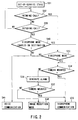
- FIG. 2 is an operation flowchart for outgoing and incoming calls according to the first embodiment of the present invention.
- the controller 5 checks if there is an incoming call from a destination terminal (step S32).
- step S32 results in YES
- the controller 5 uses the received signal to determine if the call has terminated in a videophone mode (step S33).
- step S33 results in YES
- the controller checks if the camera 11 is mounted according to a signal from the disconnection detector 20 (step S34).
- step S34 results in YES, the videophone mode takes effect immediately, enabling videophone communication (step S35).
- step S34 results in NO
- control is passed to step S36 to generate an alarm and enter a wait state for a specified time.
- the controller rechecks if the camera 11 is mounted according to a signal from the disconnection detector 20 (step S37).
- step S37 results in YES
- control is passed to step 35 to enable the videophone mode.
- step S37 results in NO
- the controller enters an image reception mode (step S38) that just receives video images from the destination terminal for communication.
- step S33 results in NO
- the controller proceeds to step S41 to enter a voice mode.
- step S32 results in NO
- the controller proceeds to step 39 to check if an outgoing call is generated.
- step S39 results in NO
- control returns to step S32.
- step S39 results in YES to indicate call origination
- the controller 5 checks if the destination terminal enters the videophone mode according to a signal from a base station (step S40).
- step S40 results in YES
- the controller follows the same procedure thereafter as for the call termination depending on whether the camera 11 is mounted (step S34).
- step S40 results in NO
- control is passed to step S41 to enable the voice mode.
- this embodiment allows the camera 11 to be mounted or detached.
- the camera can be detached for improved portability when it is not needed.
- the radio mobile terminal checks if the videophone mode takes effect. When the videophone mode takes effect, it is possible to select whether to perform videophone communication with the camera 11 mounted or to just receive images from the destination depending on needs.
- a call is to be originated from the own radio mobile terminal, it is possible to first check if the destination terminal is in the videophone mode. Only when the destination terminal is in the videophone mode, videophone communication is available with the own camera 11 mounted.
- the above-mentioned first embodiment can provide a radio mobile terminal that is conveniently transported during an out-of-service state and is easily operated as a videophone when needed.
- FIG. 3 is a block diagram showing a configuration of a radio mobile terminal according to the second embodiment of the present invention.
- memory 22 as an image storage is added to FIG. 3.
- This embodiment uses a connector 21 to import image data captured by the camera 11 during an out-of-service state.
- the imported image data is encoded in a image encoder 12 and is stored as self-portrait data in the memory 22.
- FIG. 4 is an operation flowchart for outgoing and incoming calls according to the second embodiment of the present invention. Same flowchart steps in FIGS. 2 and 4 are assigned same step numbers.
- an incoming call is confirmed at step S32 for example.
- the controller 5 checks if the camera 11 is active at next step S34. Inactive states of the camera 11 include cases where the camera 11 is not mounted or where the camera 11 is mounted but does not operate.
- step S34 results in NO
- the controller proceeds to step S42 to check if self-portrait data is stored in the memory 22.
- step S42 results in YES
- the controller transfers the encoded self-portrait data to a multiplexer 13 to enable a pseudo-videophone mode (step S43).
- Data in the memory 22 can be any character instead of a self-portrait.
- the self-portrait data which is sent to the destination terminal is the one which is stored in advance in the memory 22, rather than the realtime image (in this case, voice data is sent to the destination terminal realtime).
- step S42 results in NO, there is no image data to send, automatically causing the image reception mode (step S38).
- the controller rechecks if the camera 11 is mounted (step S37).
- step S37 results in YES, the videophone mode is enabled.
- step S37 results in NO, the voice mode is enabled.
- image data stored in the memory 22 is transmitted when the camera 11 is not mounted, or is mounted but does not operate in the videophone mode. It is possible to provide pseudo-videophone communication without transmitting a realtime image.
- This embodiment provides such an advantage that a user can set to the terminal whether the stored image data should be sent or not instead of a realtime image, prior to or during the communication.
- this embodiment includes effects of the first embodiment such as improved portability during an out-of-service state and easy operability as a videophone on demand. Since image data is stored in an encoded format, a required amount of memory can be decreased. This provides an advantage of eliminating a need to encode images at the time of videophone communication.
- the second embodiment it is possible to decrease an amount of memory required just by storing image data for a short time (say approximately 10 seconds) in the memory 22. By repeating this operation, a user can send entire data to the destination terminal.
- FIG. 5 is a block diagram showing a configuration of a radio mobile terminal according to the third embodiment of the present invention.
- the configuration in FIG. 5 is void of the image encoder 12, the disconnection detector 20, the connector 21, and the camera 11 in the configuration for the second embodiment in FIG. 3.
- the configuration in FIG. 5 has no camera as shown in FIG. 7.
- self-portrait data captured by say a digital camera is encoded on a personal computer.
- the encoded data is imported into the radio mobile terminal and is stored in the memory 22.
- the memory 22 it is also possible to use the memory 22 for storing image data transmitted from a networked server connected to a base station or from other radio mobile terminals. Pseudo-videophone communication with the destination terminal is available by sending image data stored in the memory 22.
- the third embodiment eliminates the camera and necessary components such as the image encoder 12, the disconnection detector 20, and the connector 21.
- the radio mobile terminal can be more compact and lightweight. Another advantage is more improved operability because a user need not mount or detach the camera.
- the voice transmission mode allows the radio mobile terminal to transmit voice data to the destination terminal.
- the voice reception mode allows the radio mobile terminal to receive voice data from the destination terminal.
- the radio mobile terminal can send to the destination terminal an image indicating that she or he is speaking.
- the radio mobile terminal can send to the destination terminal an image indicating that she or he is not speaking. This can eliminate unnaturalness during videophone communication.
Abstract
Description
- The present invention relates to a radio mobile terminal.
- Available radio mobile terminals include a radio mobile videophone terminal that can send and receive motion pictures as well as voices by attaching a camera to a commercially available mobile telephone. This type of videophone terminals employs a configuration as shown in FIG. 8 for communicating data including voices and images with a remote terminal via a base station.
- In FIG. 8, a high-frequency signal received at an
antenna 1 is supplied to areceiver 3 via a sharedunit 2. The supplied signal is frequency-converted to a low-frequency signal (baseband signal) based on a local oscillation signal from afrequency synthesizer 18, and then is demodulated in ademodulator 4. The demodulated signal is transferred to acontroller 5 that reads a control signal therefrom. The demodulated signal is also supplied to ademultiplexer 6. The multiplexed signal is separated into a voice signal and an image signal. - A voice signal is decoded in a
voice decoder 7 and is output from aspeaker 8 as a voice. An image signal is decoded in animage decoder 9 and is displayed on ancolor display 10 functioning as a display unit. - A
camera 11 captures a subject to generate an image signal. The generated image signal is encoded in animage encoder 12, and then is supplied to amultiplexer 13. A voice signal entered from amicrophone 14 is encoded in avoice encoder 15, and then is supplied to amultiplexer 13. Themultiplexer 13 multiplexes encoded image and voice signals. A multiplexed signal is modulated in amodulator 16, and then is sent to a base station via atransmitter 17, the sharedunit 2, and theantenna 1. Thefrequency synthesizer 18 generates frequencies needed for radio communication. Anoperation unit 19 is used for various key operations. - FIG. 9 shows an outline of the above-mentioned videophone terminal. Its body is provided with the
color display 10 and theoperation unit 19. The upper part of the body is provided with theantenna 1 and thecamera 11. - A great majority of mobile telephone users owns a small apparatus capable of voice and e-mail communication. Contrastedly, a videophone terminal uses a relatively large camera for providing videophone capabilities. For example, a videophone terminal equipped with a camera as shown in FIG. 9 has a volume of approximately 200 ml. Contrary to an ordinary mobile telephone, there has a problem of inconvenience that such an apparatus is too large and heavy to carry say in a pocket of user's clothes during an out-of-service state of the apparatus. In addition, the camera's movable parts may be damaged.
- The object of the present invention is to provide a radio mobile terminal that is conveniently transportable during an out-of-service state and can be easily used as a videophone during operation.
- To attain this object, the first aspect of the present invention is a radio mobile terminal capable of communicating data including voices and images with a destination terminal comprising:
- a transmitter/receiver;
- a camera that captures image data to be sent to the destination terminal via the transmitter/receiver;
- a display that can display image data received from the destination terminal via the transmitter/ receiver; and
- a connection unit that allows the camera to be mounted or detached depending on whether image data needs to be transmitted to the destination terminal.
-
- The second aspect of the present invention is a radio mobile terminal capable of communicating data including voices and images with a destination terminal comprising:
- a storage unit that stores image data in a format suitable for transmission to the destination terminal;
- a detector that detects an operating state of the camera when image data is transmitted to the destination terminal; and
- a transmitter that transmits image data stored in the storage unit to the destination terminal when the detector unit detects that the camera is inactive.
-
- The third aspect of the present invention is a radio mobile terminal capable of communicating data including voices and images with a destination terminal comprising:
- a transmitter/receiver;
- a storage unit that stores image data in a format suitable for transmission to the destination terminal;
- a display that can display image data received from the destination terminal via the transmitter/ receiver; and
- an image data transmitter that transmits image data stored in the storage unit via the transmitter/ receiver for videophone communication with the destination terminal.
-
- This summary of the invention does not necessarily describe all necessary features so that the invention may also be a sub-combination of these described features.
- The invention can be more fully understood from the following detailed description when taken in conjunction with the accompanying drawings, in which:
- FIG. 1 is a block diagram showing a configuration of a radio mobile terminal according to the first embodiment of the present invention.
- FIG. 2 is an operation flowchart for outgoing and incoming calls according to the first embodiment of the present invention.
- FIG. 3 is a block diagram showing a configuration of a radio mobile terminal according to the second embodiment of the present invention.
- FIG. 4 is an operation flowchart for outgoing and incoming calls according to the second embodiment of the present invention.
- FIG. 5 is a block diagram showing a configuration of a radio mobile terminal according to the third embodiment of the present invention.
- FIG. 6 is an external view (
part 1 of 2) of a radio mobile terminal according to the third embodiment, showing that the camera can be mounted or detached. - FIG. 7 is an external view (
part 2 of 2) of a radio mobile terminal according to the third embodiment, showing that no camera is provided. - FIG. 8 is a block diagram that shows a configuration of a conventional radio mobile terminal.
- FIG. 9 is an external view of a conventional radio mobile terminal.
-
- Embodiments of the present invention will be described in detail, with reference to the accompanying drawings. FIG. 1 is a block diagram showing a configuration of a radio mobile videophone terminal (simply called a radio mobile terminal hereafter) according to the first embodiment of the present invention. Same components in FIGS. 1 and 8 are assigned same numbers. Different components are chiefly described here. In FIG. 1, a
camera 11 for this embodiment can be mounted and detached via aconnector 21 as a connection unit. Adisconnection detector 20 detects whether thecamera 11 is detached or mounted, and then issues a detection signal to acontroller 5. FIG. 6 shows thecamera 11 can be freely detached or mounted on the radio mobile terminal. - When reading a detection signal indicating that the
camera 11 is detached, thecontroller 5 operates assuming that thecamera 11 is not mounted. When reading a detection signal indicating that thecamera 11 is mounted, the controller operates assuming that thecamera 11 is mounted. - FIG. 2 is an operation flowchart for outgoing and incoming calls according to the first embodiment of the present invention. While in an out-of-service state (step S31), the
controller 5 checks if there is an incoming call from a destination terminal (step S32). When step S32 results in YES, thecontroller 5 uses the received signal to determine if the call has terminated in a videophone mode (step S33). When step S33 results in YES, the controller checks if thecamera 11 is mounted according to a signal from the disconnection detector 20 (step S34). When step S34 results in YES, the videophone mode takes effect immediately, enabling videophone communication (step S35). When step S34 results in NO, control is passed to step S36 to generate an alarm and enter a wait state for a specified time. After this wait time, the controller rechecks if thecamera 11 is mounted according to a signal from the disconnection detector 20 (step S37). When step S37 results in YES, control is passed to step 35 to enable the videophone mode. When step S37 results in NO, the controller enters an image reception mode (step S38) that just receives video images from the destination terminal for communication. - When step S33 results in NO, the controller proceeds to step S41 to enter a voice mode.
- When step S32 results in NO, the controller proceeds to step 39 to check if an outgoing call is generated. When step S39 results in NO, control returns to step S32. When step S39 results in YES to indicate call origination, the
controller 5 checks if the destination terminal enters the videophone mode according to a signal from a base station (step S40). Whenstep 40 results in YES, the controller follows the same procedure thereafter as for the call termination depending on whether thecamera 11 is mounted (step S34). When step S40 results in NO, control is passed to step S41 to enable the voice mode. - As mentioned above, this embodiment allows the
camera 11 to be mounted or detached. The camera can be detached for improved portability when it is not needed. When an incoming call is received from the destination terminal, the radio mobile terminal checks if the videophone mode takes effect. When the videophone mode takes effect, it is possible to select whether to perform videophone communication with thecamera 11 mounted or to just receive images from the destination depending on needs. When a call is to be originated from the own radio mobile terminal, it is possible to first check if the destination terminal is in the videophone mode. Only when the destination terminal is in the videophone mode, videophone communication is available with theown camera 11 mounted. - Accordingly, the above-mentioned first embodiment can provide a radio mobile terminal that is conveniently transported during an out-of-service state and is easily operated as a videophone when needed.
- FIG. 3 is a block diagram showing a configuration of a radio mobile terminal according to the second embodiment of the present invention. Compared to the configuration in FIG. 1,
memory 22 as an image storage is added to FIG. 3. This embodiment uses aconnector 21 to import image data captured by thecamera 11 during an out-of-service state. The imported image data is encoded in aimage encoder 12 and is stored as self-portrait data in thememory 22. - FIG. 4 is an operation flowchart for outgoing and incoming calls according to the second embodiment of the present invention. Same flowchart steps in FIGS. 2 and 4 are assigned same step numbers. In this embodiment, an incoming call is confirmed at step S32 for example. Under this condition, when the videophone mode is confirmed at step S33, the
controller 5 checks if thecamera 11 is active at next step S34. Inactive states of thecamera 11 include cases where thecamera 11 is not mounted or where thecamera 11 is mounted but does not operate. When step S34 results in NO, the controller proceeds to step S42 to check if self-portrait data is stored in thememory 22. When step S42 results in YES, the controller transfers the encoded self-portrait data to amultiplexer 13 to enable a pseudo-videophone mode (step S43). Data in thememory 22 can be any character instead of a self-portrait. - In this case, although the realtime image data is sent from the destination terminal and displayed at the
color display 10, the self-portrait data which is sent to the destination terminal is the one which is stored in advance in thememory 22, rather than the realtime image (in this case, voice data is sent to the destination terminal realtime). - When step S42 results in NO, there is no image data to send, automatically causing the image reception mode (step S38). After step S43 or S38, the controller rechecks if the
camera 11 is mounted (step S37). When step S37 results in YES, the videophone mode is enabled. When step S37 results in NO, the voice mode is enabled. - In the above-mentioned second embodiment, image data stored in the
memory 22 is transmitted when thecamera 11 is not mounted, or is mounted but does not operate in the videophone mode. It is possible to provide pseudo-videophone communication without transmitting a realtime image. This embodiment provides such an advantage that a user can set to the terminal whether the stored image data should be sent or not instead of a realtime image, prior to or during the communication. In addition, this embodiment includes effects of the first embodiment such as improved portability during an out-of-service state and easy operability as a videophone on demand. Since image data is stored in an encoded format, a required amount of memory can be decreased. This provides an advantage of eliminating a need to encode images at the time of videophone communication. - As a variant example of the second embodiment, it is possible to decrease an amount of memory required just by storing image data for a short time (say approximately 10 seconds) in the
memory 22. By repeating this operation, a user can send entire data to the destination terminal. - FIG. 5 is a block diagram showing a configuration of a radio mobile terminal according to the third embodiment of the present invention. The configuration in FIG. 5 is void of the
image encoder 12, thedisconnection detector 20, theconnector 21, and thecamera 11 in the configuration for the second embodiment in FIG. 3. The configuration in FIG. 5 has no camera as shown in FIG. 7. - In this embodiment, self-portrait data captured by say a digital camera is encoded on a personal computer. The encoded data is imported into the radio mobile terminal and is stored in the
memory 22. It is also possible to use thememory 22 for storing image data transmitted from a networked server connected to a base station or from other radio mobile terminals. Pseudo-videophone communication with the destination terminal is available by sending image data stored in thememory 22. - In addition to effects of the second embodiment, the third embodiment eliminates the camera and necessary components such as the
image encoder 12, thedisconnection detector 20, and theconnector 21. The radio mobile terminal can be more compact and lightweight. Another advantage is more improved operability because a user need not mount or detach the camera. - For the second and third embodiments, it is possible to provide a voice transmission mode and a voice reception mode. The voice transmission mode allows the radio mobile terminal to transmit voice data to the destination terminal. The voice reception mode allows the radio mobile terminal to receive voice data from the destination terminal. In the voice transmission mode, the radio mobile terminal can send to the destination terminal an image indicating that she or he is speaking. In the voice reception mode, the radio mobile terminal can send to the destination terminal an image indicating that she or he is not speaking. This can eliminate unnaturalness during videophone communication.
Claims (14)
- A radio mobile terminal capable of communicating data including voices and images with a destination terminal comprising:a transmitter/receiver (17, 3);a camera (11) that captures image data to be sent to the destination terminal via the transmitter/ receiver (17, 3);a display (10) that can display image data received from the destination terminal via the transmitter/receiver (17, 3); anda connection unit (21) that allows the camera to be mounted or detached depending on whether image data needs to be transmitted to the destination terminal.
- A radio mobile terminal according to claim 1, characterized by further comprising:a first decision unit (5) that checks if a videophone mode takes effect when an incoming call is received from the destination terminal; anda second decision unit (20) that checks if the camera (11) is mounted,
wherein the radio mobile terminal provides voice communication services when not in the videophone mode, generates an alarm when the camera (11) is not mounted in the videophone mode, or provides videophone communication services when the camera (11) is mounted in the videophone mode. - A radio mobile terminal according to claim 2, characterized in that the second decision unit (20) rechecks if the camera (11) is mounted after a specified elapse of time from the alarm, and the radio mobile terminal provides videophone communication services when the camera (11) is mounted, or receives images when the camera (11) is not mounted.
- A radio mobile terminal according to claim 1, characterized by further comprising:a first decision unit (5) that checks if the destination terminal is in the videophone mode when a call is made to the destination terminal; anda second decision unit (20) that checks if the camera (11) is mounted,
wherein the radio mobile terminal provides voice communication services when the destination terminal is not in the videophone mode, provides videophone communication services when the destination terminal is in the videophone mode and the camera (11) is mounted, or generates an alarm when the destination terminal is in the videophone mode and the camera (11) is not mounted. - A radio mobile terminal according to claim 4, characterized in that the second decision unit (20) rechecks if the camera (11) is mounted after a specified elapse of time from the alarm, and the radio mobile terminal provides videophone communication services when the camera (11) is mounted, or receives images when the camera (11) is not mounted.
- A radio mobile terminal according to claim 2, characterized in that the radio mobile terminal provides the voice communication services in a voice transmission mode that transmits voice data to the destination terminal and in a voice reception mode that receives voice data from the destination terminal, and wherein first image data indicating that she or he is speaking is transmitted to the destination terminal in the voice transmission mode, and second image data indicating that she or he is not speaking is transmitted to the destination terminal in the voice reception mode.
- A radio mobile terminal capable of communicating data including voices and images with a destination terminal comprising:a storage unit (22) that stores image data in a format suitable for transmission to the destination terminal;a detector (5) that detects an operating state of the camera (11) when image data is transmitted to the destination terminal; anda transmitter (17) that transmits image data stored in the storage unit (22) to the destination terminal when the detector (5) detects that the camera (11) is inactive.
- A radio mobile terminal according to claim 7, characterized by further comprising:a first decision unit (5) that checks if a videophone mode takes effect when an incoming call is received from the destination terminal; anda second decision unit (20) that checks if the camera (11) is active,
wherein the radio mobile terminal provides voice communication services when not in the videophone mode, provides videophone communication services when the camera (11) is active in the videophone mode, or provides pseudo-videophone communication services by transmitting image data stored in the storage unit (22) to the destination terminal when the camera (11) is inactive in the videophone mode. - A radio mobile terminal according to claim 8, characterized in that the radio mobile terminal switches to the videophone communication services from the pseudo-videophone communication services or from the image reception, when the second decision unit (20) detects that the camera (11) is mounted.
- A radio mobile terminal according to claim 7, characterized by further comprising:a first decision unit (5) that checks if the destination terminal is in the videophone mode when a call is made to the destination terminal; anda second decision unit (20) that checks if the camera (11) is active,
wherein the radio mobile terminal provides voice communication services when the destination terminal is not in the videophone mode, provides videophone communication services when the destination terminal is in the videophone mode and the camera (11) is active, or provides pseudo-videophone communication services by transmitting image data stored in the storage unit (22) to the destination terminal when the destination terminal is in the videophone mode and the camera (11) is inactive. - A radio mobile terminal according to claim 10, characterized in that the radio mobile terminal switches to the videophone communication services from the pseudo-videophone communication services or from the image reception, when the second decision unit (20) detects that the camera (11) is mounted.
- A radio mobile terminal according to claim 8, characterized in that the radio mobile terminal provides the voice communication services in a voice transmission mode that transmits voice data to the destination terminal and in a voice reception mode that receives voice data from the destination terminal, and wherein first image data indicating that she or she is speaking is transmitted to the destination terminal in the voice transmission mode, and second image data indicating that she or he is not speaking is transmitted to the destination terminal in the voice reception mode.
- A radio mobile terminal capable of communicating data including voices and images with a destination terminal comprising:a transmitter/receiver (17, 3);a storage unit (22) that stores image data in a format suitable for transmission to the destination terminal;a display (10) that can display image data received from the destination terminal via the transmitter/receiver (17, 3); andan image data transmitter (5) that transmits image data stored in the storage unit (22) via the transmitter/receiver (17, 3) for videophone communication with the destination terminal.
- A radio mobile terminal according to claim 13, characterized in that the radio mobile terminal provides the voice data communication services in a voice transmission mode that transmits voice data to the destination terminal and in a voice reception mode that receives voice data from the destination terminal, and wherein first image data indicating that she or he is speaking is transmitted to the destination terminal in the voice transmission mode, and second image data indicating that she or he is not speaking is transmitted to the destination terminal in the voice reception mode.
Priority Applications (1)
| Application Number | Priority Date | Filing Date | Title |
|---|---|---|---|
| EP08008577A EP1947852A2 (en) | 1999-03-01 | 2000-03-01 | Radio mobile terminal with a mountable and removable camera |
Applications Claiming Priority (2)
| Application Number | Priority Date | Filing Date | Title |
|---|---|---|---|
| JP05267299A JP3308923B2 (en) | 1999-03-01 | 1999-03-01 | Wireless mobile terminal |
| JP5267299 | 1999-03-01 |
Related Child Applications (2)
| Application Number | Title | Priority Date | Filing Date |
|---|---|---|---|
| EP08008577A Division EP1947852A2 (en) | 1999-03-01 | 2000-03-01 | Radio mobile terminal with a mountable and removable camera |
| EP08008577.2 Division-Into | 2008-05-07 |
Publications (2)
| Publication Number | Publication Date |
|---|---|
| EP1033876A1 true EP1033876A1 (en) | 2000-09-06 |
| EP1033876B1 EP1033876B1 (en) | 2011-09-28 |
Family
ID=12921375
Family Applications (2)
| Application Number | Title | Priority Date | Filing Date |
|---|---|---|---|
| EP08008577A Withdrawn EP1947852A2 (en) | 1999-03-01 | 2000-03-01 | Radio mobile terminal with a mountable and removable camera |
| EP00103476A Expired - Lifetime EP1033876B1 (en) | 1999-03-01 | 2000-03-01 | Radio mobile terminal with a mountable and removable camera |
Family Applications Before (1)
| Application Number | Title | Priority Date | Filing Date |
|---|---|---|---|
| EP08008577A Withdrawn EP1947852A2 (en) | 1999-03-01 | 2000-03-01 | Radio mobile terminal with a mountable and removable camera |
Country Status (2)
| Country | Link |
|---|---|
| EP (2) | EP1947852A2 (en) |
| JP (1) | JP3308923B2 (en) |
Cited By (10)
| Publication number | Priority date | Publication date | Assignee | Title |
|---|---|---|---|---|
| EP1096771A1 (en) * | 1999-05-06 | 2001-05-02 | Kyocera Corporation | Videophone system using cellular telephone terminal |
| GB2364859A (en) * | 2000-01-28 | 2002-02-06 | Sagem | Desktop charger for mobile with camera and screen. |
| EP1235430A2 (en) * | 2001-02-26 | 2002-08-28 | Kabushiki Kaisha Toshiba | Mobile communication terminal apparatus |
| FR2828618A1 (en) * | 2001-08-10 | 2003-02-14 | France Telecom | Voice/image telecommunications system having transmitter receiver with screen/camera/antenna intermediate mechanism connecting image channel/voice section allowing voice and image connection. |
| EP1398982A1 (en) * | 2002-09-10 | 2004-03-17 | Eastman Kodak Company | Method and system for establishing a communication network |
| WO2006079873A1 (en) * | 2005-01-26 | 2006-08-03 | Majid El Bouazzaoui | Mobile telephone for voice and video image communication |
| US7487042B2 (en) * | 2004-03-31 | 2009-02-03 | Nec Corporation | Portable communication terminal equipped with navigation function and navigation method of portable communication terminal |
| TWI558202B (en) * | 2015-10-14 | 2016-11-11 | 緯創資通股份有限公司 | Imaging device, imaging system and control method thereof |
| US9503625B2 (en) | 2013-04-09 | 2016-11-22 | Rui Pedro Oliveira | Attachable smartphone camera |
| USD792497S1 (en) | 2014-04-09 | 2017-07-18 | Rui Pedro Oliveira | Attachable smartphone camera |
Families Citing this family (3)
| Publication number | Priority date | Publication date | Assignee | Title |
|---|---|---|---|---|
| JP4115245B2 (en) * | 2002-10-30 | 2008-07-09 | 富士フイルム株式会社 | Digital camera and print ordering system |
| JP4966600B2 (en) * | 2006-07-20 | 2012-07-04 | Necカシオモバイルコミュニケーションズ株式会社 | Videophone device and program |
| US11757706B2 (en) | 2019-07-19 | 2023-09-12 | Razberi Secure Technologies, Llc | Switch monitoring system and method of use |
Citations (4)
| Publication number | Priority date | Publication date | Assignee | Title |
|---|---|---|---|---|
| JPH1013561A (en) * | 1996-06-24 | 1998-01-16 | Saitama Nippon Denki Kk | Digital portable telephone set |
| US5893037A (en) * | 1994-12-09 | 1999-04-06 | Eastman Kodak Company | Combined electronic/silver-halide image capture system with cellular transmission capability |
| DE19815604A1 (en) * | 1998-04-07 | 1999-10-14 | Siemens Ag | Digital camera with radio transmission |
| EP0975132A1 (en) * | 1998-07-20 | 2000-01-26 | Alcatel | Telecommunication system comprising at least a mobile phone and at least a camera unit |
Family Cites Families (17)
| Publication number | Priority date | Publication date | Assignee | Title |
|---|---|---|---|---|
| KR920007919B1 (en) * | 1988-06-27 | 1992-09-19 | 미쯔비시 덴끼 가부시기가이샤 | Television telephone |
| JPH0260382U (en) * | 1988-10-25 | 1990-05-02 | ||
| JPH0348945U (en) * | 1989-09-19 | 1991-05-13 | ||
| JPH06268582A (en) * | 1993-03-17 | 1994-09-22 | Konica Corp | Information transmitter |
| JP2611728B2 (en) * | 1993-11-02 | 1997-05-21 | 日本電気株式会社 | Video encoding / decoding system |
| JPH07231474A (en) * | 1994-02-18 | 1995-08-29 | Nakajima Tsushin Kogyo Kk | Portable digital telephone set |
| US5584070A (en) * | 1994-12-29 | 1996-12-10 | Motorola, Inc. | Wireless pager with separable receiver unit and transmitter unit |
| DE19510737A1 (en) * | 1995-03-24 | 1996-10-02 | Thomson Brandt Gmbh | Communication terminal |
| JPH08317465A (en) * | 1995-05-17 | 1996-11-29 | Kyocera Corp | Portable communication equipment |
| JP3380835B2 (en) * | 1996-06-06 | 2003-02-24 | シャープ株式会社 | Portable videophone |
| JP3762000B2 (en) * | 1996-11-22 | 2006-03-29 | キヤノン株式会社 | Mobile phone equipment |
| US6965400B1 (en) * | 1997-02-07 | 2005-11-15 | Canon Kabushiki Kaisha | Video input apparatus and image pickup system including the apparatus |
| WO1998039906A1 (en) * | 1997-03-03 | 1998-09-11 | Kabushiki Kaisha Toshiba | Communication terminal |
| JP3492149B2 (en) * | 1997-05-09 | 2004-02-03 | 京セラ株式会社 | Wireless communication terminal device, wireless communication terminal used for the wireless communication terminal device, and digital camera |
| JPH1132115A (en) * | 1997-07-11 | 1999-02-02 | Kokusai Electric Co Ltd | Portable terminal |
| JPH1141339A (en) * | 1997-07-24 | 1999-02-12 | Sony Corp | Portable information terminal |
| JP3512327B2 (en) * | 1997-12-24 | 2004-03-29 | 京セラ株式会社 | Variable image data area method for portable videophone system |
-
1999
- 1999-03-01 JP JP05267299A patent/JP3308923B2/en not_active Expired - Fee Related
-
2000
- 2000-03-01 EP EP08008577A patent/EP1947852A2/en not_active Withdrawn
- 2000-03-01 EP EP00103476A patent/EP1033876B1/en not_active Expired - Lifetime
Patent Citations (4)
| Publication number | Priority date | Publication date | Assignee | Title |
|---|---|---|---|---|
| US5893037A (en) * | 1994-12-09 | 1999-04-06 | Eastman Kodak Company | Combined electronic/silver-halide image capture system with cellular transmission capability |
| JPH1013561A (en) * | 1996-06-24 | 1998-01-16 | Saitama Nippon Denki Kk | Digital portable telephone set |
| DE19815604A1 (en) * | 1998-04-07 | 1999-10-14 | Siemens Ag | Digital camera with radio transmission |
| EP0975132A1 (en) * | 1998-07-20 | 2000-01-26 | Alcatel | Telecommunication system comprising at least a mobile phone and at least a camera unit |
Non-Patent Citations (1)
| Title |
|---|
| PATENT ABSTRACTS OF JAPAN vol. 1998, no. 5 30 April 1998 (1998-04-30) * |
Cited By (17)
| Publication number | Priority date | Publication date | Assignee | Title |
|---|---|---|---|---|
| US7224381B2 (en) | 1999-05-06 | 2007-05-29 | Kyocera Corporation | Visual telephone system using mobile communication terminal |
| US7382395B1 (en) | 1999-05-06 | 2008-06-03 | Kyocera Corporation | Videophone system using cellular telephone terminal |
| EP1096771A4 (en) * | 1999-05-06 | 2005-06-08 | Kyocera Corp | Videophone system using cellular telephone terminal |
| EP1096771A1 (en) * | 1999-05-06 | 2001-05-02 | Kyocera Corporation | Videophone system using cellular telephone terminal |
| GB2364859A (en) * | 2000-01-28 | 2002-02-06 | Sagem | Desktop charger for mobile with camera and screen. |
| GB2364859B (en) * | 2000-01-28 | 2004-05-05 | Sagem | Mobile telephone device for videoconferencing |
| EP1235430A2 (en) * | 2001-02-26 | 2002-08-28 | Kabushiki Kaisha Toshiba | Mobile communication terminal apparatus |
| EP1235430A3 (en) * | 2001-02-26 | 2003-10-29 | Kabushiki Kaisha Toshiba | Mobile communication terminal apparatus |
| FR2828618A1 (en) * | 2001-08-10 | 2003-02-14 | France Telecom | Voice/image telecommunications system having transmitter receiver with screen/camera/antenna intermediate mechanism connecting image channel/voice section allowing voice and image connection. |
| US7027836B2 (en) | 2002-09-10 | 2006-04-11 | Eastman Kodak Company | Method and system for establishing a communication network |
| EP1398982A1 (en) * | 2002-09-10 | 2004-03-17 | Eastman Kodak Company | Method and system for establishing a communication network |
| US7487042B2 (en) * | 2004-03-31 | 2009-02-03 | Nec Corporation | Portable communication terminal equipped with navigation function and navigation method of portable communication terminal |
| WO2006079873A1 (en) * | 2005-01-26 | 2006-08-03 | Majid El Bouazzaoui | Mobile telephone for voice and video image communication |
| US9503625B2 (en) | 2013-04-09 | 2016-11-22 | Rui Pedro Oliveira | Attachable smartphone camera |
| US9961243B2 (en) | 2013-04-09 | 2018-05-01 | Rui Pedro Oliveria | Attachable smartphone camera |
| USD792497S1 (en) | 2014-04-09 | 2017-07-18 | Rui Pedro Oliveira | Attachable smartphone camera |
| TWI558202B (en) * | 2015-10-14 | 2016-11-11 | 緯創資通股份有限公司 | Imaging device, imaging system and control method thereof |
Also Published As
| Publication number | Publication date |
|---|---|
| EP1947852A2 (en) | 2008-07-23 |
| EP1033876B1 (en) | 2011-09-28 |
| JP2000253455A (en) | 2000-09-14 |
| JP3308923B2 (en) | 2002-07-29 |
Similar Documents
| Publication | Publication Date | Title |
|---|---|---|
| US5870149A (en) | Video/integrated land mobile dispatch radio and video unit | |
| KR100261607B1 (en) | Digital camera possible for telecommunication | |
| JP4282201B2 (en) | Encoded data recording device | |
| US5760824A (en) | Multimedia telephone having wireless camera and television module and method of operation thereof | |
| US20020066115A1 (en) | Portable communications device | |
| EP1033876B1 (en) | Radio mobile terminal with a mountable and removable camera | |
| JP3487280B2 (en) | Mobile phone terminal with image transmission function | |
| KR100261606B1 (en) | Digital camera possible for telecommunication | |
| EP1465424B1 (en) | Picture phone apparatus and system which checks validity of picture data | |
| EP1471719B1 (en) | Portable terminal having a camera and method for taking a photograph with the same | |
| KR100713354B1 (en) | mobile communication terminal with remote controllable camera and method for taking pictures thereof | |
| WO2000022807A2 (en) | Image communication device and method for communication terminal | |
| KR20030012745A (en) | Image transmitting/receiving method and system for mobile communication terminal equipment | |
| JP2000059748A (en) | Communication terminal | |
| JP2002027045A (en) | Electronic equipment and external connection equipment therefor | |
| JP3480714B2 (en) | Videophone system for complex mobile devices | |
| JP3766037B2 (en) | Wireless portable terminal | |
| JP2002186029A (en) | Wireless mobile terminal | |
| JP4413352B2 (en) | Mobile radio terminal and external storage unit | |
| JPH1174977A (en) | Visitor notifying system | |
| JP3567289B2 (en) | Videophone equipment | |
| KR20000043101A (en) | Videophone communication system with document transmission and reception function and display function | |
| JP3649602B2 (en) | Mobile phones and electronic devices | |
| JPH11136653A (en) | Image transfer radio communication terminal system | |
| JP2003125453A (en) | Mobile communication terminal |
Legal Events
| Date | Code | Title | Description |
|---|---|---|---|
| PUAI | Public reference made under article 153(3) epc to a published international application that has entered the european phase |
Free format text: ORIGINAL CODE: 0009012 |
|
| 17P | Request for examination filed |
Effective date: 20000301 |
|
| AK | Designated contracting states |
Kind code of ref document: A1 Designated state(s): DE FR GB |
|
| AX | Request for extension of the european patent |
Free format text: AL;LT;LV;MK;RO;SI |
|
| AKX | Designation fees paid |
Free format text: DE FR GB |
|
| 17Q | First examination report despatched |
Effective date: 20071012 |
|
| RAP1 | Party data changed (applicant data changed or rights of an application transferred) |
Owner name: KABUSHIKI KAISHA TOSHIBA |
|
| RAP1 | Party data changed (applicant data changed or rights of an application transferred) |
Owner name: FUJITSU TOSHIBA MOBILE COMMUNICATIONS LIMITED |
|
| GRAP | Despatch of communication of intention to grant a patent |
Free format text: ORIGINAL CODE: EPIDOSNIGR1 |
|
| GRAC | Information related to communication of intention to grant a patent modified |
Free format text: ORIGINAL CODE: EPIDOSCIGR1 |
|
| GRAS | Grant fee paid |
Free format text: ORIGINAL CODE: EPIDOSNIGR3 |
|
| GRAA | (expected) grant |
Free format text: ORIGINAL CODE: 0009210 |
|
| AK | Designated contracting states |
Kind code of ref document: B1 Designated state(s): DE FR GB |
|
| REG | Reference to a national code |
Ref country code: GB Ref legal event code: FG4D |
|
| REG | Reference to a national code |
Ref country code: DE Ref legal event code: R096 Ref document number: 60046472 Country of ref document: DE Effective date: 20111124 |
|
| PLBE | No opposition filed within time limit |
Free format text: ORIGINAL CODE: 0009261 |
|
| STAA | Information on the status of an ep patent application or granted ep patent |
Free format text: STATUS: NO OPPOSITION FILED WITHIN TIME LIMIT |
|
| 26N | No opposition filed |
Effective date: 20120629 |
|
| REG | Reference to a national code |
Ref country code: DE Ref legal event code: R097 Ref document number: 60046472 Country of ref document: DE Effective date: 20120629 |
|
| REG | Reference to a national code |
Ref country code: DE Ref legal event code: R082 Ref document number: 60046472 Country of ref document: DE Representative=s name: HOFFMANN - EITLE, DE |
|
| REG | Reference to a national code |
Ref country code: FR Ref legal event code: CD Owner name: FUJITSU TOSHIBA MOBILE COMMUNICATIONS LIMITED, JP Effective date: 20130128 |
|
| REG | Reference to a national code |
Ref country code: DE Ref legal event code: R081 Ref document number: 60046472 Country of ref document: DE Owner name: FUJITSU MOBILE COMMUNICATIONS LTD., JP Free format text: FORMER OWNER: FUJITSU TOSHIBA MOBILE COMMUNICATIONS LTD., KAWASAKI-SHI, JP Effective date: 20130123 Ref country code: DE Ref legal event code: R081 Ref document number: 60046472 Country of ref document: DE Owner name: FUJITSU MOBILE COMMUNICATIONS LTD., JP Free format text: FORMER OWNER: KABUSHIKI KAISHA TOSHIBA, KAWASAKI, JP Effective date: 20110930 Ref country code: DE Ref legal event code: R082 Ref document number: 60046472 Country of ref document: DE Representative=s name: HOFFMANN - EITLE, DE Effective date: 20130123 Ref country code: DE Ref legal event code: R082 Ref document number: 60046472 Country of ref document: DE Representative=s name: HOFFMANN - EITLE PATENT- UND RECHTSANWAELTE PA, DE Effective date: 20130123 Ref country code: DE Ref legal event code: R081 Ref document number: 60046472 Country of ref document: DE Owner name: FUJITSU MOBILE COMMUNICATIONS LTD., JP Free format text: FORMER OWNER: FUJITSU TOSHIBA MOBILE COMMUNICATIONS LTD., KAWASAKI-SHI, KANAGAWA, JP Effective date: 20130123 Ref country code: DE Ref legal event code: R081 Ref document number: 60046472 Country of ref document: DE Owner name: FUJITSU MOBILE COMMUNICATIONS LTD., JP Free format text: FORMER OWNER: KABUSHIKI KAISHA TOSHIBA, KAWASAKI, KANAGAWA, JP Effective date: 20110930 |
|
| REG | Reference to a national code |
Ref country code: FR Ref legal event code: PLFP Year of fee payment: 17 |
|
| REG | Reference to a national code |
Ref country code: FR Ref legal event code: PLFP Year of fee payment: 18 |
|
| PGFP | Annual fee paid to national office [announced via postgrant information from national office to epo] |
Ref country code: DE Payment date: 20170221 Year of fee payment: 18 Ref country code: FR Payment date: 20170213 Year of fee payment: 18 |
|
| PGFP | Annual fee paid to national office [announced via postgrant information from national office to epo] |
Ref country code: GB Payment date: 20170301 Year of fee payment: 18 |
|
| REG | Reference to a national code |
Ref country code: DE Ref legal event code: R119 Ref document number: 60046472 Country of ref document: DE |
|
| GBPC | Gb: european patent ceased through non-payment of renewal fee |
Effective date: 20180301 |
|
| PG25 | Lapsed in a contracting state [announced via postgrant information from national office to epo] |
Ref country code: DE Free format text: LAPSE BECAUSE OF NON-PAYMENT OF DUE FEES Effective date: 20181002 |
|
| PG25 | Lapsed in a contracting state [announced via postgrant information from national office to epo] |
Ref country code: GB Free format text: LAPSE BECAUSE OF NON-PAYMENT OF DUE FEES Effective date: 20180301 |
|
| PG25 | Lapsed in a contracting state [announced via postgrant information from national office to epo] |
Ref country code: FR Free format text: LAPSE BECAUSE OF NON-PAYMENT OF DUE FEES Effective date: 20180331 |