EP1032209A2 - Method and apparatus for monitoring circumference of vehicle - Google Patents
Method and apparatus for monitoring circumference of vehicle Download PDFInfo
- Publication number
- EP1032209A2 EP1032209A2 EP00103420A EP00103420A EP1032209A2 EP 1032209 A2 EP1032209 A2 EP 1032209A2 EP 00103420 A EP00103420 A EP 00103420A EP 00103420 A EP00103420 A EP 00103420A EP 1032209 A2 EP1032209 A2 EP 1032209A2
- Authority
- EP
- European Patent Office
- Prior art keywords
- vehicle
- picture
- monitoring
- improper
- circumference
- Prior art date
- Legal status (The legal status is an assumption and is not a legal conclusion. Google has not performed a legal analysis and makes no representation as to the accuracy of the status listed.)
- Granted
Links
Images
Classifications
-
- B—PERFORMING OPERATIONS; TRANSPORTING
- B60—VEHICLES IN GENERAL
- B60Q—ARRANGEMENT OF SIGNALLING OR LIGHTING DEVICES, THE MOUNTING OR SUPPORTING THEREOF OR CIRCUITS THEREFOR, FOR VEHICLES IN GENERAL
- B60Q1/00—Arrangement of optical signalling or lighting devices, the mounting or supporting thereof or circuits therefor
- B60Q1/26—Arrangement of optical signalling or lighting devices, the mounting or supporting thereof or circuits therefor the devices being primarily intended to indicate the vehicle, or parts thereof, or to give signals, to other traffic
- B60Q1/50—Arrangement of optical signalling or lighting devices, the mounting or supporting thereof or circuits therefor the devices being primarily intended to indicate the vehicle, or parts thereof, or to give signals, to other traffic for indicating other intentions or conditions, e.g. request for waiting or overtaking
- B60Q1/52—Arrangement of optical signalling or lighting devices, the mounting or supporting thereof or circuits therefor the devices being primarily intended to indicate the vehicle, or parts thereof, or to give signals, to other traffic for indicating other intentions or conditions, e.g. request for waiting or overtaking for indicating emergencies
-
- H—ELECTRICITY
- H04—ELECTRIC COMMUNICATION TECHNIQUE
- H04N—PICTORIAL COMMUNICATION, e.g. TELEVISION
- H04N7/00—Television systems
- H04N7/18—Closed-circuit television [CCTV] systems, i.e. systems in which the video signal is not broadcast
Definitions
- the present invention relates to a vehicle's circumference monitoring method which is employed to determine whether or not there exists an obstacle (or obstacles) around a vehicle owing to the application of a designated image processing on the circumferential picture taken by using an imaging unit installed in the vehicle, for example, a CCD camera.
- a vehicle's circumference monitoring method which can provide the result of monitoring the circumference of the owner's vehicle with high-leveled reliability and also related to a vehicle's circumference monitoring apparatus adopting the vehicle's circumference monitoring method.
- Japanese Patent Application Laid-open Publication No. 7-5076 9 discloses a vehicle's circumference monitoring method which may be used when it is required to monitor the existence of the obstacle (or obstacles) around the vehicle. According to the monitoring method, it has been carried out to apply the designated image processing on the picture around the vehicle brought by the imaging unit, for example, the CCD camera.
- the former object of the present invention described above can be accomplished by a vehicle's circumference monitoring method of monitoring whether there is an obstacle in the neighborhood of a vehicle by applying a designated image processing on a picture about the neighborhood of the vehicle, the picture being brought by using an imaging unit installed on the vehicle, the monitoring method comprising the steps of:
- the monitoring method of the present invention when the circumference monitoring accuracy is reduced, such a fact is informed to the passenger. Thus, it is possible to accomplish the high reliability in the monitoring results brought by this method.
- the second aspect of the invention when it is judged in the judging step that there is a change from the proper picture into the improper picture, it is immediately executed to inform the passenger of a fact that the present monitoring about the vehicle's neighborhood is being deteriorated in its accuracy, on the assumption that the monitoring result on the ground of such an improper picture has a reduced reliability in accuracy.
- the third aspect of the invention when it is judged in the judging step that there is a change from the improper picture into the proper picture, it is immediately executed to inform the passenger of a fact that the monitoring accuracy about the vehicle's circumference is recovered to a normal condition, on the assumption that the monitoring result on the ground of the proper picture has a recovered reliability in accuracy.
- the above judging step of the present monitoring method is carried out by applying a designated image processing on the picture taken by the imaging unit.
- the judging step of the present monitoring method is carried out with reference to an actual imaging environment in the neighborhood of the vehicle.
- a vehicle's circumference monitoring apparatus adopting a method of monitoring whether there is an obstacle in the neighborhood of a vehicle by applying a designated image processing on a picture about the neighborhood of the vehicle, the picture being taken by using an imaging unit installed in the vehicle, the monitoring apparatus comprising:
- the monitoring apparatus of the present invention when the circumference monitoring accuracy is reduced, such a fact is informed to the passenger. Thus, it is possible to always accomplish the high reliability in the monitoring results brought by this method.
- the improper picture judging unit in the above apparatus carries out the judgement of improper picture by applying a designated image processing on the picture taken by using the imaging unit.
- the improper picture judging unit in the above apparatus carries out the judgement of improper picture with reference to an actual imaging environment in the neighborhood of the vehicle.
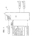
- Fig. 1 is a functional block diagram of a vehicle's circumference monitoring apparatus of the present invention.
- reference numeral 11 designates the vehicle's circumference monitoring apparatus of the invention.
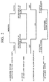
- Fig. 2 is a time chart for explanation of the operation of the vehicle's circumference monitoring apparatus 11.
- the vehicle's circumference monitoring apparatus 11 includes a CCD camera 13 operating as the imaging unit installed in the vehicle, a variety of sensors 15, an improper picture judging part 23 operating as the improper picture judging unit, an ECU 17 operating as the drive control unit, an alarm unit 19 and a display unit 21 both of which has a function as the informing unit, and an alarm stop switch 25.
- a switch will be referred to --SW-- for short, hereinafter.
- the vehicle is equipped with a plurality of CCD cameras in respective appropriate positions, for example, the vehicle's front section, the rear section, the side portions, the front/side part, the rear/side part, etc.
- these CCD cameras may be arranged in order to take pictures of various obstacles, for example, neighboring vehicles existing in the vicinity of the front section, the rear section, the side portions, the front/side part and the rear/side part of the driver's own vehicle.
- the vehicle may be equipped with only one CCD camera for purpose of imaging a picture of the obstacles existing in a designated direction from the vehicle.
- the shown apparatus 11 has a single CCD camera 13 for ease of explanation.
- the group of sensors 15 includes of a turn signal SW outputting the indicating direction of a turn-signal, a steering angle sensor for detecting the steering angle of the vehicle, a vehicle speed sensor for detecting the velocity of the vehicle, a small lamp SW for outputting the information of ON/OFF state in a not-shown small lamp, a headlight SW for outputting the information of ON/OFF state in a not-shown headlight, a gear position SW for outputting the information about the present position of a shift lever, etc.
- the ECU 17 has the following functions of:
- the alarm unit 19 has three functions as follows. That is, the first function is to raise the alarm signal on receipt of the alarm command outputted from the ECU 17. The second function is to inform the passenger (driver) of a fact that the monitoring accuracy is reduced, on receipt of a drive control command outputted from the ECU 17. The third function is to inform the passenger of a fact that the monitoring accuracy is recovered to the normal condition, on receipt of the drive control command also outputted from the ECU 17.
- the display unit 21 has a function to selectively display one of two informations: one is an information about a fact that the monitoring accuracy of the vehicle's circumference is reduced; another is an information about a fact that the monitoring accuracy of the vehicle's circumference is recovered to the normal condition.
- the alarm stop SW 25 when there is generated an information that the monitoring accuracy of the vehicle's circumference is reduced, the alarm stop SW 25 is manipulated by the passenger. That is, the alarm stop SW 25 is constituted to have a function to stop such an operation of the alarm unit 19 as informing the passenger of the large critical level.
- the ECU 17 does apply the designated image processing on a picture which has been taken by the CCD camera 13 and sequentially inputted to the ECU 17. Further in the ECU 17, it is executed to judge whether or not the so-processed picture is inappropriate for judging the critical level about the driver's own vehicle.
- CCD cameras 13 in order to take pictures exhibiting the vehicle's rear, left-side and right-side views. In this case, these pictures are subjected to the above designated image processing, so that it is carried out to judge whether the pictures are improper or not.
- the above-mentioned application of the designated image processing may be replaced with another form where the judgement is carried out while referring to "an imaging environment" around the vehicle.
- the imaging environment around the vehicle means an imaging situation containing the climatic changes, such as rainfall, snowfall, fog, etc.
- the ECU 17 As the result of the judgement of improper/proper pictures, if it is judged that the picture on image is proper, it is carried out in the ECU 17 to apply the designated image processing on the picture taken by the CCD camera 13.
- the designated image processing is represented by extracting the neighboring vehicle's lighting sections (e.g. small-lamp, headlight, etc.) and the profile of obstacles, as characterized points. While monitoring the relative positional relationship between the obstacle on recognition and the vehicle, the ECU 17 carries out the following operation.
- the ECU 17 judges the magnitude of critical level on a synthetic consideration of the relative positional relationship between the obstacle and the vehicle and the approaching speed therebetween. Thus, it is executed to judge whether there is produced a possibility of collision or involving the obstacle. Note, for comparison with the obtained magnitude of critical level, the ECU 17 has a predetermined threshold level stored in a not-shown memory.
- the ECU 17 commands the alarm unit 19 to raise the alarm signal, on the assumption of a large critical level.
- the alarm unit 19 raises the alarm signal representing the critical level being enormous. In this way, it is possible to inform the passenger on the vehicle of the enormous critical level timely. Together with the information, it can be expected to effect the great contribution on the vehicle's safety driving while preventing the occurrence of accident, such as collision, involving, or the like, in advance.
- the ECU 17 commands the alarm unit 19 and the display unit 21 to give the passenger the information about the monitoring accuracy being deteriorated. Then, on receipt of the command, the alarm unit 19 provides the passenger with a voice message, for example, "Monitoring Accuracy is Reduced. Push Alarm Stop SW.”, or any warning sound, for example, a buzzer, a chime, or the like. Also, the display unit 21 provides the passenger with a display message, such as "Monitoring Accuracy is Reduced.
- Push Alarm Stop SW.” or the lighting of a warning lamp.
- the alarm stop SW 25 is turned to its side of "alarm stop” by the passenger. Consequently, the ECU 17 commands the alarm unit 19 to stop the warning operation, as shown with (c), (d) of Fig. 2.
- the alarm unit 19 stops the warning operation based on the judgement of critical level (inactivation of alarm system).
- the ECU 17 commands the alarm unit 19 and the display unit 21 to give the passenger the information about the monitoring accuracy being recovered to the normal condition.
- the alarm unit 19 provides the passenger with a voice message, such as "Monitoring Accuracy is Recovered. Release Alarm Stop SW.”, or any sound, for example, a buzzer, a chime, or the like.
- the display unit 21 provides the passenger with a display message, such as "Monitoring Accuracy is Recovered.
- the stop and recovery of the alarm operation is controlled by the passenger through the alarm stop SW 25. While, the same SW 25 may be eliminated in the modification. Then, if it is judged that the proper picture is shifted to the improper one, the alarm operation would be automatically stopped. Conversely, if it is judged that the improper picture is recovered to the proper one, the alarm operation would be automatically recovered. Then, the voice message might be, for example, "Warning is stopped as accuracy is reduced” in case of stopping the alarm operation, "Warning is recovered as accuracy is normal” in case of recovering the alarm operation, and so on.
Abstract
Description
- The present invention relates to a vehicle's circumference monitoring method which is employed to determine whether or not there exists an obstacle (or obstacles) around a vehicle owing to the application of a designated image processing on the circumferential picture taken by using an imaging unit installed in the vehicle, for example, a CCD camera. Particularly, it relates to a vehicle's circumference monitoring method which can provide the result of monitoring the circumference of the owner's vehicle with high-leveled reliability and also related to a vehicle's circumference monitoring apparatus adopting the vehicle's circumference monitoring method.
- Japanese Patent Application Laid-open Publication No. 7-5076 9 discloses a vehicle's circumference monitoring method which may be used when it is required to monitor the existence of the obstacle (or obstacles) around the vehicle. According to the monitoring method, it has been carried out to apply the designated image processing on the picture around the vehicle brought by the imaging unit, for example, the CCD camera.
- In detail, it is executed to take "rear-side" pictures in sequence through the traveling vehicle. Upon selection of two sequence frames (scenes) from so-taken consecutive "rear-side" pictures, it is further executed to detect a displacement of an identical point through the sequence frames over as "optical flow". On the basis of the so-detected optical flow, there can be monitored the accessibility of a following vehicle against the driver's own vehicle or the same of another vehicle traveling on the neighboring traffic lane against the driver's own vehicle.
- According to the above-mentioned prior art method, since the accessibility of the following vehicle or the vehicle traveling on the neighboring traffic lane against the driver's own vehicle is detected automatically, it is expected that the information of the so-obtained accessibility to the driver (or passenger) allows to contribute the safety driving of the driver's own vehicle.
- In the above-mentioned method, however, there exists a problem to be solved. If an imaging environment around the vehicle changes due to climatic changes, for example, rainfall, snowfall, fog, etc., then the unclear pictures would be brought to cause the monitoring accuracy to be deteriorated. In the present circumstances, no measures has been taken against such a deterioration in monitoring accuracy of the above-mentioned monitoring method. In other words, there remains a possibility of providing the driver or passenger with an incorrect monitoring result including such an error. Consequently, according to the prior art monitoring method, it is impossible to provide the monitoring result of the vehicle's circumference with high reliability.
- Under the circumstances, there has been eagerly expected a development of new technique which is capable of maintaining the high reliability in the monitoring result of the vehicle's circumference usually.
- Under the circumstances, it is therefore an object of the present invention to provide a vehicle's circumference monitoring method by which it is possible to always provide the monitoring result of the vehicle's circumference with high reliability.
- It is another object of the present invention to provide a vehicle's circumference monitoring apparatus adopting such a monitoring method.
- The former object of the present invention described above can be accomplished by a vehicle's circumference monitoring method of monitoring whether there is an obstacle in the neighborhood of a vehicle by applying a designated image processing on a picture about the neighborhood of the vehicle, the picture being brought by using an imaging unit installed on the vehicle, the monitoring method comprising the steps of:
- judging whether the picture taken by using the imaging unit is improper or not; and
- when it is judged that the picture is improper,
- informing a passenger on the vehicle of a fact that the present monitoring about the vehicle's neighborhood is being deteriorated in its accuracy, on the assumption that the monitoring result on the ground of such an improper picture has a reduced reliability in accuracy.
-
- According to the monitoring method of the present invention, when the circumference monitoring accuracy is reduced, such a fact is informed to the passenger. Thus, it is possible to accomplish the high reliability in the monitoring results brought by this method.
- According to the second aspect of the invention, when it is judged in the judging step that there is a change from the proper picture into the improper picture, it is immediately executed to inform the passenger of a fact that the present monitoring about the vehicle's neighborhood is being deteriorated in its accuracy, on the assumption that the monitoring result on the ground of such an improper picture has a reduced reliability in accuracy.
- Also in the above case, when the circumference monitoring accuracy is reduced, such a fact is informed to the passenger at once. Thus, it is possible to accomplish the high reliability in the monitoring results.
- According to the third aspect of the invention, when it is judged in the judging step that there is a change from the improper picture into the proper picture, it is immediately executed to inform the passenger of a fact that the monitoring accuracy about the vehicle's circumference is recovered to a normal condition, on the assumption that the monitoring result on the ground of the proper picture has a recovered reliability in accuracy.
- In the above case, when the circumference monitoring accuracy is recovered to the normal condition, then such a fact is informed to the passenger at once. Thus, it is possible to accomplish the high reliability in the monitoring results usually.
- According to the fourth aspect of the invention, the above judging step of the present monitoring method is carried out by applying a designated image processing on the picture taken by the imaging unit.
- Then, it is possible to realize the judgement of improper picture on the ground of the taken pictures with high accuracy.
- According to the fifth aspect of the invention, the judging step of the present monitoring method is carried out with reference to an actual imaging environment in the neighborhood of the vehicle.
- Therefore, it is possible to realize the judgement of improper picture while referring to the present imaging environment including various weather, for example, rainfall, snowfall, fog, etc.
- The latter object of the present invention described above can be accomplished by a vehicle's circumference monitoring apparatus adopting a method of monitoring whether there is an obstacle in the neighborhood of a vehicle by applying a designated image processing on a picture about the neighborhood of the vehicle, the picture being taken by using an imaging unit installed in the vehicle, the monitoring apparatus comprising:
- an improper picture judging unit for judging whether the picture taken by using the imaging unit is improper or not;
- an informing unit for informing an outside of the apparatus that the monitoring accuracy about the vehicle's circumference is deteriorated; and
- a drive control unit for controlling the driving of the informing unit;
wherein, when it is judged by the improper picture judging unit that the picture taken by the imaging unit is improper, then the driving control unit operates to drive the informing unit on the assumption that the monitoring result on the ground of such an improper picture has a reduced reliability in accuracy. -
- According to the monitoring apparatus of the present invention, when the circumference monitoring accuracy is reduced, such a fact is informed to the passenger. Thus, it is possible to always accomplish the high reliability in the monitoring results brought by this method.
- According to the seventh aspect of the invention, the improper picture judging unit in the above apparatus carries out the judgement of improper picture by applying a designated image processing on the picture taken by using the imaging unit.
- Then, it is possible to realize the judgement of improper picture on the ground of the taken pictures with high accuracy.
- According to the eighth aspect of the invention, the improper picture judging unit in the above apparatus carries out the judgement of improper picture with reference to an actual imaging environment in the neighborhood of the vehicle.
- Also in the above apparatus, it is possible to realize the judgement of improper picture while referring to the actual imaging environment including various weather, for example, rainfall, snowfall, fog, etc.
- These and other objects and features of the present invention will become more fully apparent from the following description and appended claims taken in conjunction with the accompany drawings.
-
- Fig. 1 is a functional block diagram of a vehicle's circumference monitoring apparatus of the present invention; and
- Fig. 2 is a time chart for explanation of the operation of the vehicle's circumference monitoring apparatus of the present invention.
-
- One embodiment of the present invention will be described with reference to the drawings.
- Fig. 1 is a functional block diagram of a vehicle's circumference monitoring apparatus of the present invention. In Fig. 1,
reference numeral 11 designates the vehicle's circumference monitoring apparatus of the invention. Fig. 2 is a time chart for explanation of the operation of the vehicle'scircumference monitoring apparatus 11. - With reference to Fig. 1, we now describe the schematic constitution of the vehicle's
circumference monitoring apparatus 11 which adopts the vehicle's circumference monitoring method of the invention. - As shown in the figure, the vehicle's
circumference monitoring apparatus 11 includes aCCD camera 13 operating as the imaging unit installed in the vehicle, a variety ofsensors 15, an improperpicture judging part 23 operating as the improper picture judging unit, anECU 17 operating as the drive control unit, analarm unit 19 and adisplay unit 21 both of which has a function as the informing unit, and analarm stop switch 25. Note, in the specification, the word " switch" will be referred to --SW-- for short, hereinafter. - Normally, the vehicle is equipped with a plurality of CCD cameras in respective appropriate positions, for example, the vehicle's front section, the rear section, the side portions, the front/side part, the rear/side part, etc. In accordance with the requirements, these CCD cameras may be arranged in order to take pictures of various obstacles, for example, neighboring vehicles existing in the vicinity of the front section, the rear section, the side portions, the front/side part and the rear/side part of the driver's own vehicle. Of course, the vehicle may be equipped with only one CCD camera for purpose of imaging a picture of the obstacles existing in a designated direction from the vehicle. Note, the shown
apparatus 11 has asingle CCD camera 13 for ease of explanation. - The group of
sensors 15 includes of a turn signal SW outputting the indicating direction of a turn-signal, a steering angle sensor for detecting the steering angle of the vehicle, a vehicle speed sensor for detecting the velocity of the vehicle, a small lamp SW for outputting the information of ON/OFF state in a not-shown small lamp, a headlight SW for outputting the information of ON/OFF state in a not-shown headlight, a gear position SW for outputting the information about the present position of a shift lever, etc. - The
ECU 17 has the following functions of: - recognizing the obstacle(s) existing around the vehicle as the result of
the application of a designated image processing on a picture taken by the
CCD camera 13; - monitoring a relative positional relationship between the driver's own vehicle and the obstacle recognized by the above recognizing function;
- judging the magnitude of a critical level from the relative positional relationship between the driver's own vehicle and the obstacle obtained by the monitoring function;
- commanding the
alarm unit 19 to raise an alarm signal when the critical level is large in comparison with a predetermined threshold level; - judging whether the picture taken by using the
CCD camera 13 is regarded as an improper picture; and, - when the result of judgement brought by the above-judging function represents the presence of the improper picture,
- driving the
alarm unit 19 on the assumption that the monitoring accuracy of the circumference is deteriorated due to the presence of the improper picture. -
- The
alarm unit 19 has three functions as follows. That is, the first function is to raise the alarm signal on receipt of the alarm command outputted from theECU 17. The second function is to inform the passenger (driver) of a fact that the monitoring accuracy is reduced, on receipt of a drive control command outputted from theECU 17. The third function is to inform the passenger of a fact that the monitoring accuracy is recovered to the normal condition, on receipt of the drive control command also outputted from theECU 17. - Similarly, on receipt of the drive control command outputted from the
ECU 17, thedisplay unit 21 has a function to selectively display one of two informations: one is an information about a fact that the monitoring accuracy of the vehicle's circumference is reduced; another is an information about a fact that the monitoring accuracy of the vehicle's circumference is recovered to the normal condition. - According to the embodiment, when there is generated an information that the monitoring accuracy of the vehicle's circumference is reduced, the
alarm stop SW 25 is manipulated by the passenger. That is, thealarm stop SW 25 is constituted to have a function to stop such an operation of thealarm unit 19 as informing the passenger of the large critical level. - We now describe the operation of the above-mentioned vehicle's
circumference monitoring apparatus 11 with reference to Figs. 1 and 2. - First of all, the
ECU 17 does apply the designated image processing on a picture which has been taken by theCCD camera 13 and sequentially inputted to theECU 17. Further in theECU 17, it is executed to judge whether or not the so-processed picture is inappropriate for judging the critical level about the driver's own vehicle. - For example, in the vicinity of the rear section of the vehicle, there are provided some
CCD cameras 13 in order to take pictures exhibiting the vehicle's rear, left-side and right-side views. In this case, these pictures are subjected to the above designated image processing, so that it is carried out to judge whether the pictures are improper or not. - As to the judgement of improper/proper pictures, the above-mentioned application of the designated image processing may be replaced with another form where the judgement is carried out while referring to "an imaging environment" around the vehicle. Here, the imaging environment around the vehicle means an imaging situation containing the climatic changes, such as rainfall, snowfall, fog, etc.
- As the result of the judgement of improper/proper pictures, if it is judged that the picture on image is proper, it is carried out in the
ECU 17 to apply the designated image processing on the picture taken by theCCD camera 13. For example, the designated image processing is represented by extracting the neighboring vehicle's lighting sections (e.g. small-lamp, headlight, etc.) and the profile of obstacles, as characterized points. While monitoring the relative positional relationship between the obstacle on recognition and the vehicle, theECU 17 carries out the following operation. - That is, on the ground of the vehicle information (e.g. lighting conditions of turn signals, steering angle, vehicle speed) brought from the group of
sensors 15, it is determined whether or not the driver's own vehicle is now changing its traveling lane (or turning to the right or left). For example, if it is judged that the driver's own vehicle is now changing its traveling lane, then theECU 17 judges the magnitude of critical level on a synthetic consideration of the relative positional relationship between the obstacle and the vehicle and the approaching speed therebetween. Thus, it is executed to judge whether there is produced a possibility of collision or involving the obstacle. Note, for comparison with the obtained magnitude of critical level, theECU 17 has a predetermined threshold level stored in a not-shown memory. - As the result of comparing the present critical level with the threshold level, when it is judged that the driver's own vehicle may be subjected to the traffic collision or involving, the
ECU 17 commands thealarm unit 19 to raise the alarm signal, on the assumption of a large critical level. - On receipt of the command, the
alarm unit 19 raises the alarm signal representing the critical level being enormous. In this way, it is possible to inform the passenger on the vehicle of the enormous critical level timely. Together with the information, it can be expected to effect the great contribution on the vehicle's safety driving while preventing the occurrence of accident, such as collision, involving, or the like, in advance. - When it is judged that the proper picture on image varies to the improper picture, it is regarded in the
ECU 17 that the monitoring based on the improper picture has a reduced reliability. Therefore, as shown with (a), (b) of Fig. 2. theECU 17 commands thealarm unit 19 and thedisplay unit 21 to give the passenger the information about the monitoring accuracy being deteriorated. Then, on receipt of the command, thealarm unit 19 provides the passenger with a voice message, for example, "Monitoring Accuracy is Reduced. Push Alarm Stop SW.", or any warning sound, for example, a buzzer, a chime, or the like. Also, thedisplay unit 21 provides the passenger with a display message, such as "Monitoring Accuracy is Reduced. Push Alarm Stop SW.", or the lighting of a warning lamp. In this way, thealarm stop SW 25 is turned to its side of "alarm stop" by the passenger. Consequently, theECU 17 commands thealarm unit 19 to stop the warning operation, as shown with (c), (d) of Fig. 2. On receipt of the command, thealarm unit 19 stops the warning operation based on the judgement of critical level (inactivation of alarm system). - On the contrary, if it is judged that the improper picture on image varies to the proper picture, it is regarded in the
ECU 17 that the monitoring based on the proper picture has a recovered reliability. Therefore, as shown with (a), (b) of Fig. 2. theECU 17 commands thealarm unit 19 and thedisplay unit 21 to give the passenger the information about the monitoring accuracy being recovered to the normal condition. On receipt of the command, thealarm unit 19 provides the passenger with a voice message, such as "Monitoring Accuracy is Recovered. Release Alarm Stop SW.", or any sound, for example, a buzzer, a chime, or the like. Also, thedisplay unit 21 provides the passenger with a display message, such as "Monitoring Accuracy is Recovered. Release Alarm Stop SW.", or the light-out of a warning lamp. Under such a situation, when the passenger manipulates thealarm stop SW 25 to the side of "alarm recover", then theECU 17 transmits a command of recovering the alarm operation to the alarm unit 19 (activation of alarm system), as shown with (c), (d) of Fig. 2. On receipt of the command, thealarm unit 19 starts the warning operation as the result of the judgement of the critical level. - It will be understood by those skilled in the art that the foregoing description is one of preferred embodiments of the disclosed shield terminal and the manufacturing method. Various changes and modifications may be made to the present invention without departing from the spirit and scope of the invention.
- For example, we hereinabove describe the embodiment where the stop and recovery of the alarm operation is controlled by the passenger through the
alarm stop SW 25. While, thesame SW 25 may be eliminated in the modification. Then, if it is judged that the proper picture is shifted to the improper one, the alarm operation would be automatically stopped. Conversely, if it is judged that the improper picture is recovered to the proper one, the alarm operation would be automatically recovered. Then, the voice message might be, for example, "Warning is stopped as accuracy is reduced" in case of stopping the alarm operation, "Warning is recovered as accuracy is normal" in case of recovering the alarm operation, and so on.
Claims (8)
- A vehicle's circumference monitoring method of monitoring whether there is an obstacle in the neighborhood of a vehicle by applying a designated image processing on a picture about the neighborhood of the vehicle, the picture being brought by using an imaging unit on the vehicle, the monitoring method comprising the steps of:judging whether the picture taken by using the imaging unit is improper or not; andwhen it is judged that the picture is improper, informing a passenger on the vehicle of a fact that the present monitoring about the vehicle's neighborhood is being deteriorated in its accuracy, on the assumption that the monitoring result on the ground of such an improper picture has a reduced reliability in accuracy.
- A vehicle's circumference monitoring method as claimed in Claim 1, wherein, when it is judged in the judging step that there is a change from the proper picture into the improper picture, it is immediately executed to inform the passenger of a fact that the present monitoring about the vehicle's neighborhood is being deteriorated in its accuracy, on the assumption that the monitoring result on the ground of such an improper picture has a reduced reliability in accuracy.
- A vehicle's circumference monitoring method as claimed in Claim 1, wherein, when it is judged in the judging step that there is a change from the improper picture into the proper picture, it is immediately executed to inform the passenger of a fact that the monitoring accuracy about the vehicle's circumference is recovered to a normal condition, on the assumption that the monitoring result on the ground of the proper picture has a recovered reliability in accuracy.
- A vehicle's circumference monitoring method as claimed in Claim 1, wherein the judging step is carried out by applying a designated image processing on the picture taken by the imaging unit.
- A vehicle's circumference monitoring method as claimed in Claim 1, wherein the judging step is carried out with reference to an actual imaging environment in the neighborhood of the vehicle.
- A vehicle's circumference monitoring apparatus adopting a method of monitoring whether there is an obstacle in the neighborhood of a vehicle by applying a designated image processing on a picture about the neighborhood of the vehicle, the picture being brought by using an imaging unit of the vehicle, the monitoring apparatus comprising:an improper picture judging unit for judging whether the picture taken by using the imaging unit is improper or not;an informing unit for informing an outside of the apparatus that the monitoring accuracy of the vehicle's circumference is deteriorated; anda drive control unit for controlling the driving of the informing unit; wherein, when it is judged by the improper picture judging unit that the picture taken by the imaging unit is improper, then the driving control unit operates to drive the informing unit on the assumption that the monitoring result on the ground of such an improper picture has a reduced reliability in accuracy.
- A vehicle's circumference monitoring apparatus as claimed in Claim 6, wherein the improper picture judging unit carries out the judgement of improper picture by applying a designated image processing on the picture taken by using the imaging unit.
- A vehicle's circumference monitoring apparatus as claimed in Claim 6, wherein the improper picture judging unit carries out the judgement of improper picture with reference to the present imaging situation in the neighborhood of the vehicle.
Applications Claiming Priority (2)
| Application Number | Priority Date | Filing Date | Title |
|---|---|---|---|
| JP4886799 | 1999-02-25 | ||
| JP11048867A JP2000247197A (en) | 1999-02-25 | 1999-02-25 | Vehicle periphery monitoring method and vehicle periphery monitoring device to which this method is applied |
Publications (3)
| Publication Number | Publication Date |
|---|---|
| EP1032209A2 true EP1032209A2 (en) | 2000-08-30 |
| EP1032209A3 EP1032209A3 (en) | 2001-08-29 |
| EP1032209B1 EP1032209B1 (en) | 2009-01-28 |
Family
ID=12815248
Family Applications (1)
| Application Number | Title | Priority Date | Filing Date |
|---|---|---|---|
| EP20000103420 Expired - Lifetime EP1032209B1 (en) | 1999-02-25 | 2000-02-25 | Method and apparatus for monitoring circumference of vehicle |
Country Status (3)
| Country | Link |
|---|---|
| EP (1) | EP1032209B1 (en) |
| JP (1) | JP2000247197A (en) |
| DE (1) | DE60041467D1 (en) |
Cited By (3)
| Publication number | Priority date | Publication date | Assignee | Title |
|---|---|---|---|---|
| US6583730B2 (en) | 2000-07-28 | 2003-06-24 | Lang-Mekra North America, Llc | Surveillance apparatus for a vehicle |
| WO2004086766A1 (en) * | 2003-03-24 | 2004-10-07 | Daimlerchrysler Ag | Switching on/off concept for an automobile night vision system |
| FR2860466A1 (en) * | 2003-10-02 | 2005-04-08 | Daimler Chrysler Ag | DEVICE FOR IMPROVING VISION CONDITIONS IN A VEHICLE |
Families Citing this family (5)
| Publication number | Priority date | Publication date | Assignee | Title |
|---|---|---|---|---|
| US6642840B2 (en) | 2000-07-28 | 2003-11-04 | Lang-Mekra North Amicica, Llc | Rearview mirror assembly with monitor |
| DE10036875A1 (en) | 2000-07-28 | 2002-02-28 | Mekra Lang Gmbh & Co Kg | Rearview mirror for vehicle, has monitor connected to camera which captures fields before, laterally and behind vehicle |
| JP5129909B2 (en) * | 2001-07-23 | 2013-01-30 | トヨタ自動車株式会社 | Driving support device |
| JP2012040445A (en) * | 2011-12-02 | 2012-03-01 | Terumo Corp | Peritoneal dialysis device |
| JP6238715B2 (en) * | 2013-12-09 | 2017-11-29 | 株式会社トヨタマップマスター | Route search apparatus and method, computer program for searching for route, and recording medium recording computer program |
Citations (2)
| Publication number | Priority date | Publication date | Assignee | Title |
|---|---|---|---|---|
| US5521633A (en) * | 1992-09-25 | 1996-05-28 | Yazaki Corporation | Motor vehicle obstacle monitoring system using optical flow processing |
| JPH10119672A (en) * | 1996-10-16 | 1998-05-12 | Isuzu Motors Ltd | Vehicle outside monitoring device |
Family Cites Families (1)
| Publication number | Priority date | Publication date | Assignee | Title |
|---|---|---|---|---|
| JP3452268B2 (en) * | 1993-08-06 | 2003-09-29 | 矢崎総業株式会社 | Rear side monitoring method for vehicles |
-
1999
- 1999-02-25 JP JP11048867A patent/JP2000247197A/en active Pending
-
2000
- 2000-02-25 DE DE60041467T patent/DE60041467D1/en not_active Expired - Lifetime
- 2000-02-25 EP EP20000103420 patent/EP1032209B1/en not_active Expired - Lifetime
Patent Citations (2)
| Publication number | Priority date | Publication date | Assignee | Title |
|---|---|---|---|---|
| US5521633A (en) * | 1992-09-25 | 1996-05-28 | Yazaki Corporation | Motor vehicle obstacle monitoring system using optical flow processing |
| JPH10119672A (en) * | 1996-10-16 | 1998-05-12 | Isuzu Motors Ltd | Vehicle outside monitoring device |
Non-Patent Citations (1)
| Title |
|---|
| PATENT ABSTRACTS OF JAPAN vol. 1998, no. 10, 31 August 1998 (1998-08-31) & JP 10 119672 A (ISUZU MOTORS LTD), 12 May 1998 (1998-05-12) * |
Cited By (3)
| Publication number | Priority date | Publication date | Assignee | Title |
|---|---|---|---|---|
| US6583730B2 (en) | 2000-07-28 | 2003-06-24 | Lang-Mekra North America, Llc | Surveillance apparatus for a vehicle |
| WO2004086766A1 (en) * | 2003-03-24 | 2004-10-07 | Daimlerchrysler Ag | Switching on/off concept for an automobile night vision system |
| FR2860466A1 (en) * | 2003-10-02 | 2005-04-08 | Daimler Chrysler Ag | DEVICE FOR IMPROVING VISION CONDITIONS IN A VEHICLE |
Also Published As
| Publication number | Publication date |
|---|---|
| EP1032209A3 (en) | 2001-08-29 |
| EP1032209B1 (en) | 2009-01-28 |
| DE60041467D1 (en) | 2009-03-19 |
| JP2000247197A (en) | 2000-09-12 |
Similar Documents
| Publication | Publication Date | Title |
|---|---|---|
| JP4654208B2 (en) | Vehicle environment recognition device | |
| US7378947B2 (en) | Device and method for the active monitoring of the safety perimeter of a motor vehicle | |
| CN106004879A (en) | Driving assistant system of vehicle and method for controlling same | |
| US20200283021A1 (en) | Vehicle control apparatus, vehicle, and control method | |
| US11223775B2 (en) | Method and apparatus for the spatially resolved detection of an object outside a transportation vehicle with the aid of a sensor installed in a transportation vehicle | |
| CN111204333A (en) | Vehicle forward blind spot detection and warning system | |
| JP2005309797A (en) | Warning device for pedestrian | |
| JP4541609B2 (en) | Stop line recognition device and vehicle driving support device using the stop line recognition device | |
| US20040210364A1 (en) | Vehicle drive assist system | |
| KR20200115640A (en) | A system and method for detecting the risk of collision between a vehicle and a secondary object located in a lane adjacent to the vehicle when changing lanes | |
| JP3246243B2 (en) | Lane departure warning device | |
| US20120206275A1 (en) | Blind area warning for vehicles | |
| CN112119433A (en) | Safeguarding and taking safety measures against dangerous points by vehicle warning | |
| EP1032209B1 (en) | Method and apparatus for monitoring circumference of vehicle | |
| US11893802B2 (en) | Systems and methods for traffic light identification | |
| JP2021049892A (en) | Automatic operation system | |
| JP3639008B2 (en) | Wiper control device | |
| JP2002109699A (en) | Vehicle drive support device | |
| JP5166975B2 (en) | Vehicle periphery monitoring device and vehicle periphery monitoring method | |
| JP6932631B2 (en) | Image display device and driving support system | |
| JP2004310525A (en) | Vehicular image processor | |
| KR102419764B1 (en) | Emergency assistance system with acoustic external warning | |
| JP6973566B2 (en) | Driving support device | |
| JP2013146029A (en) | Vehicle periphery monitoring device | |
| KR20220060003A (en) | Vehicle collision preventignd system and control method thereof |
Legal Events
| Date | Code | Title | Description |
|---|---|---|---|
| PUAI | Public reference made under article 153(3) epc to a published international application that has entered the european phase |
Free format text: ORIGINAL CODE: 0009012 |
|
| 17P | Request for examination filed |
Effective date: 20000225 |
|
| AK | Designated contracting states |
Kind code of ref document: A2 Designated state(s): AT BE CH CY DE DK ES FI FR GB GR IE IT LI LU MC NL PT SE |
|
| AX | Request for extension of the european patent |
Free format text: AL;LT;LV;MK;RO;SI |
|
| PUAL | Search report despatched |
Free format text: ORIGINAL CODE: 0009013 |
|
| AK | Designated contracting states |
Kind code of ref document: A3 Designated state(s): AT BE CH CY DE DK ES FI FR GB GR IE IT LI LU MC NL PT SE |
|
| AX | Request for extension of the european patent |
Free format text: AL;LT;LV;MK;RO;SI |
|
| RIC1 | Information provided on ipc code assigned before grant |
Free format text: 7H 04N 7/18 A, 7B 60R 1/00 B |
|
| AKX | Designation fees paid |
Free format text: DE FR IT |
|
| RAP1 | Party data changed (applicant data changed or rights of an application transferred) |
Owner name: YAZAKI CORPORATION |
|
| 17Q | First examination report despatched |
Effective date: 20080221 |
|
| GRAP | Despatch of communication of intention to grant a patent |
Free format text: ORIGINAL CODE: EPIDOSNIGR1 |
|
| GRAS | Grant fee paid |
Free format text: ORIGINAL CODE: EPIDOSNIGR3 |
|
| GRAA | (expected) grant |
Free format text: ORIGINAL CODE: 0009210 |
|
| AK | Designated contracting states |
Kind code of ref document: B1 Designated state(s): DE FR IT |
|
| REF | Corresponds to: |
Ref document number: 60041467 Country of ref document: DE Date of ref document: 20090319 Kind code of ref document: P |
|
| PLBE | No opposition filed within time limit |
Free format text: ORIGINAL CODE: 0009261 |
|
| STAA | Information on the status of an ep patent application or granted ep patent |
Free format text: STATUS: NO OPPOSITION FILED WITHIN TIME LIMIT |
|
| 26N | No opposition filed |
Effective date: 20091029 |
|
| PG25 | Lapsed in a contracting state [announced via postgrant information from national office to epo] |
Ref country code: IT Free format text: LAPSE BECAUSE OF NON-PAYMENT OF DUE FEES Effective date: 20090225 |
|
| PGRI | Patent reinstated in contracting state [announced from national office to epo] |
Ref country code: IT Effective date: 20110616 |
|
| REG | Reference to a national code |
Ref country code: FR Ref legal event code: PLFP Year of fee payment: 16 |
|
| PGFP | Annual fee paid to national office [announced via postgrant information from national office to epo] |
Ref country code: DE Payment date: 20150218 Year of fee payment: 16 Ref country code: IT Payment date: 20150209 Year of fee payment: 16 |
|
| PGFP | Annual fee paid to national office [announced via postgrant information from national office to epo] |
Ref country code: FR Payment date: 20150210 Year of fee payment: 16 |
|
| REG | Reference to a national code |
Ref country code: DE Ref legal event code: R119 Ref document number: 60041467 Country of ref document: DE |
|
| REG | Reference to a national code |
Ref country code: FR Ref legal event code: ST Effective date: 20161028 |
|
| PG25 | Lapsed in a contracting state [announced via postgrant information from national office to epo] |
Ref country code: IT Free format text: LAPSE BECAUSE OF NON-PAYMENT OF DUE FEES Effective date: 20160225 |
|
| PG25 | Lapsed in a contracting state [announced via postgrant information from national office to epo] |
Ref country code: DE Free format text: LAPSE BECAUSE OF NON-PAYMENT OF DUE FEES Effective date: 20160901 Ref country code: FR Free format text: LAPSE BECAUSE OF NON-PAYMENT OF DUE FEES Effective date: 20160229 |