EP1027985A2 - Image forming system including a print head having a plurality of ink channel pistons, and method of assembling the system and print head - Google Patents
Image forming system including a print head having a plurality of ink channel pistons, and method of assembling the system and print head Download PDFInfo
- Publication number
- EP1027985A2 EP1027985A2 EP00200340A EP00200340A EP1027985A2 EP 1027985 A2 EP1027985 A2 EP 1027985A2 EP 00200340 A EP00200340 A EP 00200340A EP 00200340 A EP00200340 A EP 00200340A EP 1027985 A2 EP1027985 A2 EP 1027985A2
- Authority
- EP
- European Patent Office
- Prior art keywords
- ink
- meniscus
- piston
- heater
- providing
- Prior art date
- Legal status (The legal status is an assumption and is not a legal conclusion. Google has not performed a legal analysis and makes no representation as to the accuracy of the status listed.)
- Granted
Links
Images


Classifications
-
- B—PERFORMING OPERATIONS; TRANSPORTING
- B41—PRINTING; LINING MACHINES; TYPEWRITERS; STAMPS
- B41J—TYPEWRITERS; SELECTIVE PRINTING MECHANISMS, i.e. MECHANISMS PRINTING OTHERWISE THAN FROM A FORME; CORRECTION OF TYPOGRAPHICAL ERRORS
- B41J2/00—Typewriters or selective printing mechanisms characterised by the printing or marking process for which they are designed
- B41J2/005—Typewriters or selective printing mechanisms characterised by the printing or marking process for which they are designed characterised by bringing liquid or particles selectively into contact with a printing material
- B41J2/01—Ink jet
- B41J2/135—Nozzles
- B41J2/14—Structure thereof only for on-demand ink jet heads
- B41J2/14451—Structure of ink jet print heads discharging by lowering surface tension of meniscus
Definitions
- This invention generally relates to printing devices and methods, and more particularly relates to an image forming system including a print head having plurality of ink channel pistons, and method of assembling the system and print head.
- Ink jet printing is recognized as a prominent contender in digitally controlled, electronic printing because of its non-impact, low-noise characteristics, use of plain paper and avoidance of toner transfers and fixing. For these reasons, DOD ( D rop- O n- D emand) inkjet printers have achieved commercial success for home and office use.
- Other types of piezoelectric drop-on-demand printers utilize piezoelectric crystals in push mode, shear mode, and squeeze mode.
- patterning of the piezoelectric crystal and the complex high voltage drive circuitry necessary to drive each printer nozzle are disadvantageous to cost effective manufacturability and performance.
- the relatively large size of the piezo transducer prevents close nozzle spacing making it difficult for this technology to be used in high resolution page width printhead design.
- thermal ink jet printing typically requires a heater energy of approximately 20 ⁇ J over a period of approximately 2 ⁇ sec to heat the ink to a temperature 280-400°C to cause rapid, homogeneous formation of a bubble.
- Rapid bubble formation provides momentum for drop ejection. Collapse of the bubble causes a pressure pulse due to the implosion of the bubble.
- the high temperatures needed with this device necessitates use of special inks, complicates driver electronics, and precipitates deterioration of heater elements through kogation, which is the accumulation of ink combustion by-products that encrust the heater with debris. Such encrusted debris interferes with thermal efficiency of the heater.
- An inkjet printing system provides a liquid printing system incorporating nozzles having a meniscus poised at positive pressure extending from nozzle tip.
- a heater surrounding the nozzle tip applies heat to the edge of the meniscus.
- This technique provides a drop-on-demand printing mechanism wherein the means of selecting drops to be printed produces a difference in position between selected drops and drops which are not selected. However, the difference in position is insufficient to cause ink drops to overcome surface tension and separate from the body of ink.
- separation means is provided to cause separation of the selected drops from the body of ink.
- this method of selection that uses surface tension reduction requires specialized inks and the requirement of poising the meniscus at a positive pressure may cause undesirable nozzle leakage due to contamination on any single nozzle.
- Yet another inkjet printing system provides an image forming apparatus incorporating an ink jet printhead where a single transducer is used to periodically oscillate the body of ink in order to poise ink drops and form a meniscus.
- This device further comprises an ink drop separator associated with the transducer for lowering the surface tension of the meniscus in order to separate the meniscus from the ink body to form an ink droplet.
- this device operates satisfactorily for its intended purpose, use of the Lebens et al. device may nonetheless lead to propagation of unwanted pressure waves in an ink manifold belonging to the printhead. These unwanted pressure waves in the ink manifold can in turn lead to inadvertent ejection of drops. Therefore, it is desirable to localize the effects of the pressure to the ink cavities and their respective nozzles.
- An object of the present invention is to provide an image forming system and method for forming an image on a recording medium, the system including a thermo-mechanically activated DOD ( D rop O n D emand) printhead including a DOD print head having a plurality of ink channel pistons, and method of assembling the system and print head.
- a thermo-mechanically activated DOD D rop O n D emand
- DOD DOD
- the invention resides in an image forming system, comprising a piston adapted to momentarily pressurize an ink body so that an ink meniscus extends from the ink body, the meniscus having a predetermined surface tension; and an ink droplet separator associated with said piston for lowering the surface tension of the meniscus while the meniscus extends from the ink body, whereby said droplet separator separates the meniscus from the ink body to form an ink droplet while the surface tension lowers.
- the system includes a printhead defining a plurality of ink channels in the print head. Each channel holds an ink body therein and terminates in a nozzle orifice.
- a micromachined piston is disposed in each channel for alternately pressurizing and depressurizing the ink body.
- An ink meniscus extends from the ink body and out the nozzle orifice while the ink body is pressurized.
- the ink meniscus retracts into the nozzle orifice while the ink body is depressurized.
- An ink droplet separator is also provided for lowering surface tension of the meniscus as the meniscus extends from the orifice. The extended meniscus severs from the ink body to form an ink droplet as the droplet separator lowers the surface tension to a predetermined value.
- a feature of the present invention is the provision of a single micromachined array of pistons in fluid communication with a plurality of ink menisci reposed at respective ones of a plurality of nozzles for pressurizing the menisci, so that the menisci extend from the nozzles as the menisci are pressurized and retract into the nozzles as the menisci are depressurized.
- Another feature of the present invention is the provision of a plurality of heaters in heat transfer communication with respective ones of the ink menisci, the heaters being selectively actuated only as the menisci extend a predetermined distance from the nozzles for separating selected ones of the menisci from their respective nozzles.
- Another advantage of the present invention is that use thereof increases reliability of the printhead.
- Another advantage of the present invention is that use thereof conserves power.
- Yet another advantage of the present invention is that the heaters belonging thereto are longer-lived.
- a further advantage of the present invention is that use thereof allows more nozzles per unit volume of the printhead to increase image resolution.
- An additional advantage of the present invention is that use thereof allows faster printing.
- Still another advantage of the present invention is that a vapor bubble is not formed at the heater, which vapor bubble formation might otherwise lead to kogation.
- Yet another advantage of the present invention is that use thereof reduces propagation of unwanted pressure waves in the ink manifold of the printhead, which reduced propagation in turn reduces risk of inadvertent ejection of drops.
- System 10 comprises an input image source 40, which may be raster image data from a scanner (not shown) or computer (also not shown), or outline image data in the form of a PDL ( P age D escription L anguage) or other form of digital image representation.
- Image source 40 is connected to an image processor 50, which converts the image data to a pixel-mapped page image comprising continuous tone data.
- Image processor 50 is in turn connected to a digital halftoning unit 60 which halftones the continuous tone data produced by image processor 50.
- image memory unit 70 is temporarily stored in an image memory unit 70 connected to halftoning unit 60.
- image memory unit 70 may be a full page memory or a so-called band memory.
- output data from image memory unit 70 is read by a master control circuit 80, which controls both a piston array driver circuit 90 and a heater control circuit 100.
- system 10 further comprises a microcontroller 110 connected to master control circuit 80 for controlling master control circuit 80.
- control circuit 80 in turn controls piston array driver circuit 90 and heater control circuit 100.
- Controller 110 is also connected to an ink pressure regulator 120 for controlling regulator 120.
- a purpose of regulator 120 is to regulate pressure in an ink reservoir 130 connected to regulator 120, which reservoir 130 contains a reservoir of ink therein for marking recording medium 30.
- Ink reservoir 130 is connected, such as by means of a conduit 140, to a printhead 150, which may be a DOD inkjet printhead.
- a transport control unit 160 for electronically controlling a recording medium transport mechanism 170.
- Transport mechanism 170 may include a plurality of motorized rollers 180 aligned with printhead 150 and adapted to intimately engage recording medium 30.
- rollers 180 rotatably engage recording medium 30 for transporting recording medium 30 past printhead 150.
- pagewidth printhead 150 remains stationary and recording medium 30 is moved past stationary printhead 150.
- scanning-type printhead 150 is moved along one axis (in a sub-scanning direction) and recording medium 30 is moved along an orthogonal axis (in a main scanning direction), so as to obtain relative raster motion.
- printhead 150 comprises an array of micromachined ink channel pistons 250 positioned above nozzles 190, each nozzle 190 capable of ejecting ink droplet 200.
- Each nozzle 190 is etched in an orifice plate or substrate 195, which may be silicon, and defines a channel shaped chamber 210 in nozzle 190.
- Chamber 210 is in communication with reservoir 130, such as by means of previously mentioned conduit 140, for receiving ink from reservoir 130. In this manner, ink flows through conduit 140 and into chamber 210 such that an ink body 220 is formed in chamber 210.
- nozzle 190 defines a nozzle orifice 230 communicating with chamber 210.
- orifice 230 may have a radius of approximately 8 ⁇ m.
- Pistons 250 are actuated by the vertical movement of a motive source 251 via the movement of a plate 252 and membrane 253 covering the top of printhead 150. It may be appreciated that the ink covers a shaft portion of piston 250, but not does not touch the inside portion of plate 252 and membrane 253. Downward movement can be provided by an elastic seal 254 interconnecting plate 252 and body of print head 150.
- each piston 250 is positioned above its respective nozzle 190.
- each nozzle 190 is capable of ejecting ink droplet 200 (see Fig. 7) therefrom to be intercepted by recording medium 30.
- nozzle 190 defines a nozzle orifice 230 communicating with chamber 210.
- An ink meniscus 240 is disposed at orifice 230 when ink body 220 is disposed in chamber 210.
- meniscus 240 in the absence of an applied heat pulse, meniscus 240 is capable of oscillating between a first position 245a (shown, for example, as a dashed curved line) and an extended meniscus second position 245b. It may be appreciated that, in order for meniscus 240 to oscillate, ink body 220 must itself oscillate because meniscus 240 is integrally formed with ink body 220, which ink body 220 is a substantially incompressible fluid. To oscillate each ink body 220, piston 250, which is in fluid communication with ink body 220 in chambers 210, is moved in a vertical direction by motive source 251.
- Motive source 251 may be formed of a piezoelectric material capable of accepting, for example, a 25 volt, 50 ⁇ s square wave electrical pulse, although other pulse shapes, such as triangular or sinusoidal may be used, if desired. In any event, motive source 251 is capable of vertical movement so as to evince oscillatory motion on piston 250 from its unstressed position 255a to a downwardly position 255b. More specifically, when piston 250 moves to downward position 255b, volume of chamber 210 decreases and meniscus 240 is extended outward from orifice 230 as shown by position 245b.
- volume of chamber 210 returns to its initial state and ink is retracted into nozzle with meniscus 240 returning to concave first position 245a.
- the movement of array of micromachined pistons 250 spans all chambers 210 and therefore simultaneously pressurizes and depressurizes all chambers 210 to confine the effects of pressure pulses produced by motion of motive source 251. These pressure effects are confined to each chamber 210 and are localized to its associated piston 250.
- the motion of motive source 251 produces a pressure pulse in a particular chamber 210 substantially due only to the motion of the piston 250 associated with that chamber and not, for example, with the motion of other pistons 250 associated with other chambers 210 or with the motion of plate 252. This is because ink covers only a portion of shaft 250 but does not touch inside portion of plate 252.
- Fig. 3 it is seen that as piston 250 is moved downwardly to position 255b, volume of chamber 210 decreases so that meniscus 240 extends from the orifice 230 as shown by position 245b. If the amplitude of the piston 250 motion is further increased by, for example, approximately 20%, necking of the meniscus occurs with ink drops separating from nozzles 190 during movement of piston 250 to its position 255b. With proper adjustment of the amplitude of oscillatory motion of piston 250, repeated extension and retraction of the meniscus 240 is possible without the separation of drops in the absence of a heat pulse. To ensure necking instability of meniscus 240 when a heat pulse is applied, the ink is formulated to have a surface tension which decreases with increasing temperature. Consequently, as described in detail hereinbelow, a heat pulse is applied to meniscus 240 to separate an ink droplet from nozzle 190.
- an ink droplet separator such as an annular heater 270
- an annular heater 270 is provided for separating meniscus from orifice 230, so that droplet 200 leaves orifice 230 and travels to recording medium 30.
- an intermediate layer 260 which may be formed from silicon dioxide, covers substrate 195.
- Heater 270 rests on substrate 195 and preferably is in fluid communication with meniscus 240 for separating meniscus 240 from nozzle 190 by lowering surface tension of meniscus 240.
- annular heater 270 surrounds orifice 230 and is connected to a suitable electrode layer 280 which supplies electrical energy to heater 270, so that the temperature of heater 270 increases.
- annular heater 270 forms a generally circular lip or orifice rim 285 encircling orifice 230.
- heater 270 is preferably annular, heater 270 may comprise one or more arcuate-shaped segments disposed adjacent to orifice 230, if desired. Heater 270 may advantageously comprise arcuate-shaped segments in order to provide directional control of the separated ink drop.
- heater 270 may be doped polysilicon. Also, by way of example only and not by way of limitation, heater 270 may be actuated for a time period of approximately 20 ⁇ s.
- intermediate layer 260 provides thermal and electrical insulation between heater 270 and electrode layer 280 on the one hand and electrical insulation between heater 270 and substrate 195 on the other hand.
- an exterior protective layer 290 is also provided for protecting substrate 195, heater 270, intermediate layer 260 and electrode layer 280 from damage by resisting corrosion and fouling.
- protective layer 290 may be polytetrafluroethylene chosen for its anti-corrosive and anti-fouling properties.
- printhead 150 is relatively simple and inexpensive to fabricate and also easily integrated into a CMOS process.
- piston array 250 and heater 270 are controlled by the previously mentioned piston array driver circuit 90 and heater control circuit 100, respectively.
- Piston array driver circuit 90 and heater control circuit 100 are in turn controlled by master control circuit 80.
- Master control circuit 80 controls piston array driver circuit 90 so that pistons 250 oscillate at a predetermined frequency.
- master control circuit 80 reads data from image memory unit 70 and applies time-varying electrical pulses to predetermined ones of heaters 270 to selectively release droplets 200 in order to form ink marks at pre-selected locations on recording medium 30. It is in this manner that printhead 150 forms image 20 according to data that was temporarily stored in image memory unit 70.
- meniscus 240 outwardly extends from orifice 230 to a maximum distance "L" before reversal of transducer 250 motion causes meniscus 240 to retract in the absence of a heat pulse.
- Figures 4 and 5 specifically depict the case in which a heat pulse is applied via heater 270 while the meniscus 240 is outwardly expanding. Timing of the heat pulse is controlled by heater control circuit 100.
- the application of heat by heater 270 causes a temperature rise of the ink in neck region 320.
- temperature of neck region 230 is preferably greater than 100°C but less than a temperature which would cause the ink to form a vapor bubble.
- the total drop ejection cycle may be approximately 144 ⁇ s.
- piston array motion and timing of heat pulses are electrically controlled by piston array driver circuit 90 and heater control circuit 100, respectively.
- tat system 10 obtains a thermo-mechanically activated printhead 150 because heaters 270 supply thermal energy to meniscus 240 and piston array 250 supplies mechanical energy to meniscus 240 in order to produce droplet 200.
- the method of assembling the system and print head of present invention is described in detail hereinbelow with reference to Figs. 8a-8i.
- substrate 195 which preferably is a silicon wafer, is shown having a sacrificial layer 325, preferably silicon oxide, and a nozzle plate layer 330, preferably nickel, deposited on a bottom side of substrate.
- Top mask 335 is a composite mask, known in the art of semiconductor processing, comprising in accord with the present invention, a mask 336 of a first material, preferably silicon oxide, having openings 336a, a second layer mask 337, formed of a second material, preferably silicon nitride, having openings 337a, and an optically patterned photoresist mask 338 having openings 338a overlying masks 337 and 336.
- a first material preferably silicon oxide
- second layer mask 337 formed of a second material, preferably silicon nitride, having openings 337a
- an optically patterned photoresist mask 338 having openings 338a overlying masks 337 and 336.
- Masks 336 and 337 are made preferably by the steps of first depositing a layer of silicon nitride, patterning this layer by conventional photolithography using photoresist and etching the layer to have openings 337a, removing the photoresist, then depositing a layer of silicon oxide and patterning this layer by etching to have openings 338a, the process of patterning in each case being accomplished by conventional photolithography and selective plasma etching, preferably reactive ion etching, as is well known in the art of semiconductor processing.
- Bottom mask 340, having openings 340a, is an optically patterned photoresist.
- spacer trenches 345 are etched anisotropically into substrate 195, preferably silicon, by high density reactive ion etching.
- mask 338 is removed, for example by exposure to an oxygen plasma (Fig. 8c).
- anisotropic silicon etching is continued, preferably again using the etching process previously used to define spacer trenches 345, until piston connection regions 350 have been formed.
- This process also forms piston clearance regions 350a which are simultaneously etched as extensions of spacer trenches 345.
- Piston defining trenches 355 may extend to the surface of sacrificial layer 325, although this is not required at this stage of processing. Pistons 250 with connecting shafts 360 and posts 365 are thereby formed, whereby piston defining trenches 355 extend to the surface of sacrificial layer 325.
- mask 336 is removed, preferably by wet etching in the case when the material of mask 336 is silicon oxide.
- Anisotropic etching is continued, preferably using the process used to define spacer trenches 345.
- the continuation of anisotropic etching defines regions 370 (FIG. 8e) which, as will be described, contact ink piston connection regions 350 which are made deeper by this etch but not so deep as to contact sacrificial layer 325, and piston top surfaces 375.
- Posts 365 are thereby made shorter to become support posts 365a having top surfaces 365b.
- nozzle plate 330 is etched anisotropically to provide bore openings 380 in nozzle plate 330, for example by reactive ion etching from the bottom side of the structure.
- Fig. 8h an isotropic wet etch is used to remove sacrificial layer 325 in cavity regions 356 underlying the pistons 250 thereby forming a piston bottom surface 38c. As shown in FIG. 8h, this etch does not remove sacrificial layer 325 substantially under posts 365 because posts 365 are spaced from bore openings 380.
- heater rings 270 surrounding the bore regions on the nozzle plate surface are fabricated. The fabrication of heater rings is well known in the art of Micro Electro Mechanical Structures (MEMS).
- the heater rings 270 are preferably fabricated by the steps of deposition of a resistive layer, preferably polysilicon, and patterning of the layer into an annulus surrounding the openings 380. Alternatively, heater rings may be provided before etching bore openings 380.
- piston connection region 350, piston clearance region 350a, cavity region 356, bore openings 80, and a portion of ink region 370 are filled with ink 80, for example an aqueous based ink containing a dye.
- ink 80 for example an aqueous based ink containing a dye.
- the filling is to an extent that the ink covers a portion of the piston shafts 360 but does not contact the bottom side of membrane 253.
- an ink meniscus 256 is formed below membrane 253 (Fig. 2)
- the ink may be pressurized by pressuring the air above the meniscus 256 to cause protrusion of drops of ink out of the bore openings 380 even in the absence of motion of the pistons 250, but this is not required for the operation of the device.
- a piston array is advantageously employed in accordance with the present invention to confine the effects of pressure pulses at cavity regions 356 produced by motion of membrane 253 to only those effect associated with corresponding pistons 250.
- motion of membrane 253 produces a pressure pulse at a particular cavity region 356 substantially due only to the motion of the piston 250 associated with that cavity and not, for example, with the motion of other pistons 250 associated with other cavities or with the motion of membrane 253 directly.
- the preferred method of operation of the device is one in which the motion of the membrane 253 produces only localized pressure pulses a plurality of cavity regions 356, and does not, for example, produce pressure waves traveling with substantial energy throughout the ink or throughout portions of the substrate 195.
- This preferred method assures that the pressure pulses near any cavity region coming from any source other than the motion of the piston in that cavity region do not significantly alter the ejection of drops.
- the pressure pulses in all cavities are substantially identical providing the motion of each piston is the same. This is possible in accordance with the present invention because the piston shafts travel in a vertical direction and thereby couple their motion only weakly to the ink.
- the preferred method of operation of the device is one in which the motion of the membrane 253 does not produces pressure pulses in the ink by directly contacting the ink, since such pulses would spread to all cavity regions, as is well know in the art of acoustic coupling.
- FIG. 9 there is shown a second embodiment printhead 150.
- This second embodiment printhead is substantially similar to the first embodiment printhead, except that motive source 251 is formed of a metallic material that is responsive to an electromagnetic field 400.
- Electromagnetic field 400 is generated by each of a first electromagnet 410a and a second electromagnet 410b spaced-apart from first electromagnet 410a (as shown). Electromagnets 410a/b are operated out-of-phase for reasons disclosed presently. As second electromagnet 410b is operated, the first electromagnetic 410a is not operated. In this manner, electromagnetic field 400 emitted from second electromagnetic 410b will cause piston 250 to downwardly move in chamber 210, so that meniscus 240 extends from orifice 230.
- first electromagnet 410a As first electromagnet 410a is operated, the second electromagnet 410b is not operated. In this manner, electromagnetic field 400 emitted from first electromagnet 410a will cause piston 250 to upwardly move in chamber 210 to retract meniscus 240 into orifice 230.
- a third embodiment printhead 150 is substantially similar to the first embodiment printhead, except that motive source 251 is formed of a piezoelectric material responsive to an electrical field, such that motive source 251 deflects when subjected to the electric field.
- motive source 251 is formed of a piezoelectric material responsive to an electrical field, such that motive source 251 deflects when subjected to the electric field.
- piston 250 will deflect downwardly in chamber 210.
- piston 250 is caused to move upwardly in chamber 210 assisted by seal 254, as previously mentioned.
- an important aspect of the present invention is that a novel and unobvious technique is provided for significantly reducing the energy required to select which ink droplets to eject. This is achieved by separating the means for selecting ink drops from the means for ensuring that selected drops separate from the body of ink. Only the drop separation mechanism must be driven by individual signals supplied to each nozzle. In addition, the drop selection mechanism can be applied simultaneously to all nozzles.
- an advantage of the present invention is that there is no significant static back pressure acting on chamber 210 and ink body 220. Such static back pressure might otherwise cause inadvertent leakage of ink from orifice 230. Therefore, image forming system 10 has increased reliability by avoiding inadvertent leakage of ink.
- Another advantage of the present invention is that the invention requires less heat energy than prior art thermal bubblejet printheads. This is so because the heater 270 is used to lower the surface tension of a small region (i.e., neck region 320) of the meniscus 240 rather than requiring latent heat of evaporation to form a vapor bubble. This is important for high density packing of nozzles so that heating of the substrate does not occur. Therefore, image forming system 10 uses less energy per nozzle than prior art devices.
- heaters 270 are longer-lived because the low power levels that are used prevent cavitation damage due to collapse of vapor bubbles and kogation damage due to burned ink depositing on heater surfaces.
- a further advantage of the present invention is that image resolution is increased compared to prior art devices. This is possible because transducer 250 does not in itself eject droplet 200; rather, piston 250 merely oscillates meniscus 240 so that meniscus 240 is pressurized and moves to position 245a in preparation for ejection. It is the lowering of surface tension by means of heater 270 that finally allows droplet 200 to be ejected.
- Use of piston 250 to merely oscillate meniscus 240 rather than to eject droplet 200 eliminates so-called "cross-talk" between chambers 210 during droplet ejection because the heat applied to the meniscus at one nozzle selected for actuation does not affect the meniscus at an adjacent nozzle. In other words, there is no significant heat transfer between adjacent nozzles.
- Elimination of cross-talk between chambers 210 allows more chambers 210 per unit volume of printhead 150. More chambers 210 per unit volume of printhead 150 results in a denser packing of chambers 210 in printhead 150, which in turn allows for higher image resolution.
- An additional advantage of the present invention is that the velocity of the drop 200 of approximately 7 m/sec is large enough that no additional means of moving drops to recording medium 30 are necessary in contrast to prior art low energy use printing systems.
- ink body 220 need not be in a liquid state at room temperature. That is, solid "hot melt” inks can be used, if desired, by heating printhead 150 and reservoir 130 above the melting point of such a solid "hot melt” ink.
- system 10 may comprise a transducer and heater in combination with a surface tension reducing chemical agent injector mechanism in the same device, if desired. This chemical agent will assist in decreasing surface tension to enhance drop separation.
- an image forming system and method for forming an image on a recording medium including a printhead having a plurality of micromachined ink channel pistons, and method of assembling the system and print head.
Abstract
Description
- This invention generally relates to printing devices and methods, and more particularly relates to an image forming system including a print head having plurality of ink channel pistons, and method of assembling the system and print head.
- Ink jet printing is recognized as a prominent contender in digitally controlled, electronic printing because of its non-impact, low-noise characteristics, use of plain paper and avoidance of toner transfers and fixing. For these reasons, DOD (Drop-On-Demand) inkjet printers have achieved commercial success for home and office use.
- For example, U.S. Pat. No. 3,946,398, which issued to Kyser et al. in 1970, discloses a drop-on-demand ink jet printer which applies a high voltage to a piezoelectric crystal, causing the crystal to bend. As the crystal bends, pressure is applied to an ink reservoir for jetting ink drops on demand. Other types of piezoelectric drop-on-demand printers utilize piezoelectric crystals in push mode, shear mode, and squeeze mode. However, patterning of the piezoelectric crystal and the complex high voltage drive circuitry necessary to drive each printer nozzle are disadvantageous to cost effective manufacturability and performance. Also, the relatively large size of the piezo transducer prevents close nozzle spacing making it difficult for this technology to be used in high resolution page width printhead design.
- Great Britain Pat. No. 2,007,162, which issued to Endo et al. in 1979, discloses an electrothermal drop-on-demand ink jet printer that applies a power pulse to an electrothermal heater which is in thermal contact with water based ink in a nozzle. A small quantity of ink rapidly evaporates, forming a bubble which causes drops of ink to be ejected from small apertures along an edge of a heater substrate. This technology is known as thermal ink jet printing.
- More specifically, thermal ink jet printing typically requires a heater energy of approximately 20 µJ over a period of approximately 2 µsec to heat the ink to a temperature 280-400°C to cause rapid, homogeneous formation of a bubble. Rapid bubble formation provides momentum for drop ejection. Collapse of the bubble causes a pressure pulse due to the implosion of the bubble. The high temperatures needed with this device necessitates use of special inks, complicates driver electronics, and precipitates deterioration of heater elements through kogation, which is the accumulation of ink combustion by-products that encrust the heater with debris. Such encrusted debris interferes with thermal efficiency of the heater. In addition, such encrusted debris may migrate to the ink meniscus to undesirably alter the viscous and chemical properties of the ink meniscus. Also, the 10 Watt active power consumption of each heater prevents manufacture of low cost, high speed pagewidth printheads.
- An inkjet printing system provides a liquid printing system incorporating nozzles having a meniscus poised at positive pressure extending from nozzle tip. A heater surrounding the nozzle tip applies heat to the edge of the meniscus. This technique provides a drop-on-demand printing mechanism wherein the means of selecting drops to be printed produces a difference in position between selected drops and drops which are not selected. However, the difference in position is insufficient to cause ink drops to overcome surface tension and separate from the body of ink. In this regard, separation means is provided to cause separation of the selected drops from the body of ink. However, this method of selection that uses surface tension reduction requires specialized inks and the requirement of poising the meniscus at a positive pressure may cause undesirable nozzle leakage due to contamination on any single nozzle. Application of an electric field or the adjustment of receiver proximity is thereafter used to cause separation of the selected drops from the body of the ink. However, the electric field strength needed to separate the selected drop is above the value for breakdown in air so that a close spacing between nozzle and receiver is needed, but there is still the possibility of arcing. Also, causing separation of the drop using proximity mode, for which the paper receiver must be in close proximity to the orifice in order to separate the drop from the orifice, is unreliable due to the presence of relatively large dust particles typically found in an uncontrolled environment.
- Yet another inkjet printing system provides an image forming apparatus incorporating an ink jet printhead where a single transducer is used to periodically oscillate the body of ink in order to poise ink drops and form a meniscus. This device further comprises an ink drop separator associated with the transducer for lowering the surface tension of the meniscus in order to separate the meniscus from the ink body to form an ink droplet. Although this device operates satisfactorily for its intended purpose, use of the Lebens et al. device may nonetheless lead to propagation of unwanted pressure waves in an ink manifold belonging to the printhead. These unwanted pressure waves in the ink manifold can in turn lead to inadvertent ejection of drops. Therefore, it is desirable to localize the effects of the pressure to the ink cavities and their respective nozzles.
- Therefore, there remains a long-felt need for an ink jet printer providing such advantages as reduced cost, increased speed, higher print quality, greater reliability, less power usage, and simplicity of construction and operation.
- An object of the present invention is to provide an image forming system and method for forming an image on a recording medium, the system including a thermo-mechanically activated DOD (Drop On Demand) printhead including a DOD print head having a plurality of ink channel pistons, and method of assembling the system and print head.
- With this object in view, the invention resides in an image forming system, comprising a piston adapted to momentarily pressurize an ink body so that an ink meniscus extends from the ink body, the meniscus having a predetermined surface tension; and an ink droplet separator associated with said piston for lowering the surface tension of the meniscus while the meniscus extends from the ink body, whereby said droplet separator separates the meniscus from the ink body to form an ink droplet while the surface tension lowers.
- According to an embodiment of the present invention, the system includes a printhead defining a plurality of ink channels in the print head. Each channel holds an ink body therein and terminates in a nozzle orifice. A micromachined piston is disposed in each channel for alternately pressurizing and depressurizing the ink body. An ink meniscus extends from the ink body and out the nozzle orifice while the ink body is pressurized. In addition, the ink meniscus retracts into the nozzle orifice while the ink body is depressurized. An ink droplet separator is also provided for lowering surface tension of the meniscus as the meniscus extends from the orifice. The extended meniscus severs from the ink body to form an ink droplet as the droplet separator lowers the surface tension to a predetermined value.
- A feature of the present invention is the provision of a single micromachined array of pistons in fluid communication with a plurality of ink menisci reposed at respective ones of a plurality of nozzles for pressurizing the menisci, so that the menisci extend from the nozzles as the menisci are pressurized and retract into the nozzles as the menisci are depressurized.
- Another feature of the present invention is the provision of a plurality of heaters in heat transfer communication with respective ones of the ink menisci, the heaters being selectively actuated only as the menisci extend a predetermined distance from the nozzles for separating selected ones of the menisci from their respective nozzles.
- Another advantage of the present invention is that use thereof increases reliability of the printhead.
- Another advantage of the present invention is that use thereof conserves power.
- Yet another advantage of the present invention is that the heaters belonging thereto are longer-lived.
- A further advantage of the present invention is that use thereof allows more nozzles per unit volume of the printhead to increase image resolution.
- An additional advantage of the present invention is that use thereof allows faster printing.
- Still another advantage of the present invention is that a vapor bubble is not formed at the heater, which vapor bubble formation might otherwise lead to kogation.
- Yet another advantage of the present invention is that use thereof reduces propagation of unwanted pressure waves in the ink manifold of the printhead, which reduced propagation in turn reduces risk of inadvertent ejection of drops.
- These and other objects, features and advantages of the present invention will become apparent to those skilled in the art upon a reading of the following detailed description when taken in conjunction with the drawings wherein there is shown and described illustrative embodiments of the invention.
- While the specification concludes with claims particularly pointing-out and distinctly claiming the subject matter of the present invention, it is believed the invention will be better understood from the following description when taken in conjunction with the accompanying drawings wherein:
- Figure 1 shows a functional block diagram of an image forming system of the present invention including a first embodiment printhead;
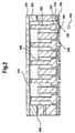
- Figure 2 is a view in vertical section of the printhead including a plurality of ink channels formed therein, each channel having a micromachined ink channel piston therein for pressurizing and depressurizing the ink channel;
- Figure 3 is a view in vertical section of a printhead associated with each channel, the nozzle having an ink body therein and an ink meniscus connected to the ink body;
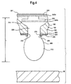
- Figure 4 is a view in vertical section of the printhead nozzle showing the ink meniscus outwardly extending from the nozzle, this view also showing a heater surrounding the nozzle and in heat transfer communication with the extended ink meniscus to lower surface tension of the extended ink meniscus in order to separate the extended ink meniscus from the nozzle;
- Figure 5 is a view in vertical section of the nozzle having the meniscus further outwardly extending from the nozzle as the surface tension lowers;
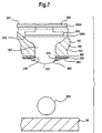
- Figure 6 is a view in vertical section of the nozzle, the meniscus shown in the act of severing from the nozzle and obtaining a generally oblong elliptical shape;
- Figure 7 is a view in vertical section of the nozzle, the meniscus having been severed from the nozzle so as to define a generally spherically-shaped ink droplet traveling toward a recording medium;
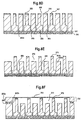
- Figures 8a-8i are views in vertical section of the print head during assembly of the printhead;
- Figure 9 is a view in vertical section of a second embodiment printhead belonging to the present invention; and
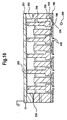
- Figure 10 is a view in vertical section of a third embodiment printhead belonging to the present invention.
-
- The present description will be directed in particular to elements forming part of, or cooperating more directly with, apparatus in accordance with the present invention. It is to be understood that elements not specifically shown or described may take various forms well known to those skilled in the art.
- Therefore, referring to Fig. 1, there is shown a functional block diagram of an image forming system, generally referred to as 10, for forming an
image 20 on arecording medium 30. Recordingmedium 30 may be, for example, cut sheets of paper or transparency.System 10 comprises aninput image source 40, which may be raster image data from a scanner (not shown) or computer (also not shown), or outline image data in the form of a PDL (Page Description Language) or other form of digital image representation.Image source 40 is connected to animage processor 50, which converts the image data to a pixel-mapped page image comprising continuous tone data.Image processor 50 is in turn connected to adigital halftoning unit 60 which halftones the continuous tone data produced byimage processor 50. This halftoned bitmap image data is temporarily stored in animage memory unit 70 connected tohalftoning unit 60. Depending on the configuration selected forsystem 10,image memory unit 70 may be a full page memory or a so-called band memory. For reasons described more fully hereinbelow, output data fromimage memory unit 70 is read by amaster control circuit 80, which controls both a pistonarray driver circuit 90 and aheater control circuit 100. - Referring again to Fig. 1,
system 10 further comprises amicrocontroller 110 connected tomaster control circuit 80 for controllingmaster control circuit 80. As previously mentioned,control circuit 80 in turn controls pistonarray driver circuit 90 andheater control circuit 100.Controller 110 is also connected to anink pressure regulator 120 for controllingregulator 120. A purpose ofregulator 120 is to regulate pressure in anink reservoir 130 connected toregulator 120, whichreservoir 130 contains a reservoir of ink therein for markingrecording medium 30.Ink reservoir 130 is connected, such as by means of aconduit 140, to aprinthead 150, which may be a DOD inkjet printhead. In addition, connected tocontroller 110 is atransport control unit 160 for electronically controlling a recordingmedium transport mechanism 170.Transport mechanism 170 may include a plurality ofmotorized rollers 180 aligned withprinthead 150 and adapted to intimately engagerecording medium 30. In this regard,rollers 180 rotatably engagerecording medium 30 for transportingrecording medium 30past printhead 150. It may be understood that for the purpose of so-called "pagewidth" printing,printhead 150 remains stationary andrecording medium 30 is moved paststationary printhead 150. On the other hand, for the purpose of so-called "scanning-type" printing,printhead 150 is moved along one axis (in a sub-scanning direction) andrecording medium 30 is moved along an orthogonal axis (in a main scanning direction), so as to obtain relative raster motion. - Turning now to Fig. 2,
printhead 150 comprises an array of micromachinedink channel pistons 250 positioned abovenozzles 190, eachnozzle 190 capable of ejectingink droplet 200. Eachnozzle 190 is etched in an orifice plate orsubstrate 195, which may be silicon, and defines a channel shapedchamber 210 innozzle 190.Chamber 210 is in communication withreservoir 130, such as by means of previously mentionedconduit 140, for receiving ink fromreservoir 130. In this manner, ink flows throughconduit 140 and intochamber 210 such that anink body 220 is formed inchamber 210. In addition,nozzle 190 defines anozzle orifice 230 communicating withchamber 210. By way of example only and not by way of limitation,orifice 230 may have a radius of approximately 8 µm.Pistons 250 are actuated by the vertical movement of amotive source 251 via the movement of aplate 252 andmembrane 253 covering the top ofprinthead 150. It may be appreciated that the ink covers a shaft portion ofpiston 250, but not does not touch the inside portion ofplate 252 andmembrane 253. Downward movement can be provided by anelastic seal 254interconnecting plate 252 and body ofprint head 150. - Referring to Fig. 3, each
piston 250 is positioned above itsrespective nozzle 190. Of course, eachnozzle 190 is capable of ejecting ink droplet 200 (see Fig. 7) therefrom to be intercepted by recordingmedium 30. In addition,nozzle 190 defines anozzle orifice 230 communicating withchamber 210. Anink meniscus 240 is disposed atorifice 230 whenink body 220 is disposed inchamber 210. - Referring again to Fig. 3, in the absence of an applied heat pulse,
meniscus 240 is capable of oscillating between afirst position 245a (shown, for example, as a dashed curved line) and an extended meniscussecond position 245b. It may be appreciated that, in order formeniscus 240 to oscillate,ink body 220 must itself oscillate becausemeniscus 240 is integrally formed withink body 220, whichink body 220 is a substantially incompressible fluid. To oscillate eachink body 220,piston 250, which is in fluid communication withink body 220 inchambers 210, is moved in a vertical direction bymotive source 251.Motive source 251 may be formed of a piezoelectric material capable of accepting, for example, a 25 volt, 50 µs square wave electrical pulse, although other pulse shapes, such as triangular or sinusoidal may be used, if desired. In any event,motive source 251 is capable of vertical movement so as to evince oscillatory motion onpiston 250 from itsunstressed position 255a to adownwardly position 255b. More specifically, whenpiston 250 moves todownward position 255b, volume ofchamber 210 decreases andmeniscus 240 is extended outward fromorifice 230 as shown byposition 245b. Similarly, whenpiston 250 returns to itsunstressed position 255a, volume ofchamber 210 returns to its initial state and ink is retracted into nozzle withmeniscus 240 returning to concavefirst position 245a. As described hereinabove, the movement of array ofmicromachined pistons 250 spans allchambers 210 and therefore simultaneously pressurizes and depressurizes allchambers 210 to confine the effects of pressure pulses produced by motion ofmotive source 251. These pressure effects are confined to eachchamber 210 and are localized to its associatedpiston 250. In other words, the motion ofmotive source 251 produces a pressure pulse in aparticular chamber 210 substantially due only to the motion of thepiston 250 associated with that chamber and not, for example, with the motion ofother pistons 250 associated withother chambers 210 or with the motion ofplate 252. This is because ink covers only a portion ofshaft 250 but does not touch inside portion ofplate 252. - Still referring to Fig. 3, it is seen that as
piston 250 is moved downwardly toposition 255b, volume ofchamber 210 decreases so thatmeniscus 240 extends from theorifice 230 as shown byposition 245b. If the amplitude of thepiston 250 motion is further increased by, for example, approximately 20%, necking of the meniscus occurs with ink drops separating fromnozzles 190 during movement ofpiston 250 to itsposition 255b. With proper adjustment of the amplitude of oscillatory motion ofpiston 250, repeated extension and retraction of themeniscus 240 is possible without the separation of drops in the absence of a heat pulse. To ensure necking instability ofmeniscus 240 when a heat pulse is applied, the ink is formulated to have a surface tension which decreases with increasing temperature. Consequently, as described in detail hereinbelow, a heat pulse is applied tomeniscus 240 to separate an ink droplet fromnozzle 190. - Therefore, as best seen in Figs. 4, 5 and 6, an ink droplet separator, such as an
annular heater 270, is provided for separating meniscus fromorifice 230, so thatdroplet 200 leavesorifice 230 and travels to recordingmedium 30. More specifically, anintermediate layer 260, which may be formed from silicon dioxide, coverssubstrate 195.Heater 270 rests onsubstrate 195 and preferably is in fluid communication withmeniscus 240 for separatingmeniscus 240 fromnozzle 190 by lowering surface tension ofmeniscus 240. More specifically,annular heater 270 surroundsorifice 230 and is connected to asuitable electrode layer 280 which supplies electrical energy toheater 270, so that the temperature ofheater 270 increases. Moreover,annular heater 270 forms a generally circular lip ororifice rim 285 encirclingorifice 230. Althoughheater 270 is preferably annular,heater 270 may comprise one or more arcuate-shaped segments disposed adjacent to orifice 230, if desired.Heater 270 may advantageously comprise arcuate-shaped segments in order to provide directional control of the separated ink drop. By way of example only and not by way of limitation,heater 270 may be doped polysilicon. Also, by way of example only and not by way of limitation,heater 270 may be actuated for a time period of approximately 20 µs. Thus,intermediate layer 260 provides thermal and electrical insulation betweenheater 270 andelectrode layer 280 on the one hand and electrical insulation betweenheater 270 andsubstrate 195 on the other hand. In addition, an exteriorprotective layer 290 is also provided for protectingsubstrate 195,heater 270,intermediate layer 260 andelectrode layer 280 from damage by resisting corrosion and fouling. By way of example only and not by way of limitation,protective layer 290 may be polytetrafluroethylene chosen for its anti-corrosive and anti-fouling properties. In the above configuration,printhead 150 is relatively simple and inexpensive to fabricate and also easily integrated into a CMOS process. - Returning briefly to Fig. 1,
piston array 250 andheater 270 are controlled by the previously mentioned pistonarray driver circuit 90 andheater control circuit 100, respectively. Pistonarray driver circuit 90 andheater control circuit 100 are in turn controlled bymaster control circuit 80.Master control circuit 80 controls pistonarray driver circuit 90 so thatpistons 250 oscillate at a predetermined frequency. Moreover,master control circuit 80 reads data fromimage memory unit 70 and applies time-varying electrical pulses to predetermined ones ofheaters 270 to selectively releasedroplets 200 in order to form ink marks at pre-selected locations on recordingmedium 30. It is in this manner that printhead 150forms image 20 according to data that was temporarily stored inimage memory unit 70. - Referring to Figs. 3, 4, 5 and 7,
meniscus 240 outwardly extends fromorifice 230 to a maximum distance "L" before reversal oftransducer 250 motion causesmeniscus 240 to retract in the absence of a heat pulse. Figures 4 and 5 specifically depict the case in which a heat pulse is applied viaheater 270 while themeniscus 240 is outwardly expanding. Timing of the heat pulse is controlled byheater control circuit 100. The application of heat byheater 270 causes a temperature rise of the ink inneck region 320. In this regard, temperature ofneck region 230 is preferably greater than 100°C but less than a temperature which would cause the ink to form a vapor bubble. Reduction in surface tension causes increased necking instability of the expandingmeniscus 240 as depicted in Fig. 5. This increased necking instability, along with the reversal of motion ofpiston array 250 causesneck region 320 to break (i.e., sever). When this occurs, anew meniscus 240 forms after droplet separation and retracts intoorifice 230. The momentum of thedroplet 200 that is achieved is sufficient, with droplet velocities of 7m/sec, to carry it to recordingmedium 30 for printing. The remaining newly formedink meniscus 240 is retracted back intonozzle 190 aspiston 250 returns to itsfirst position 255a. This newly formedmeniscus 240 can then be extended during the next cycle ofmotive source 251 and downward vertical movement ofpiston array 250. By way of example only and not by way of limitation, the total drop ejection cycle may be approximately 144µs. In this manner, piston array motion and timing of heat pulses are electrically controlled by pistonarray driver circuit 90 andheater control circuit 100, respectively. Thus, it may be appreciated from the description hereinabove,tat system 10 obtains a thermo-mechanically activatedprinthead 150 becauseheaters 270 supply thermal energy tomeniscus 240 andpiston array 250 supplies mechanical energy tomeniscus 240 in order to producedroplet 200. The method of assembling the system and print head of present invention is described in detail hereinbelow with reference to Figs. 8a-8i. - Therefore, referring to Fig. 8a,
substrate 195, which preferably is a silicon wafer, is shown having asacrificial layer 325, preferably silicon oxide, and anozzle plate layer 330, preferably nickel, deposited on a bottom side of substrate. Atop mask 335 on a top surface ofsubstrate 195 and abottom mask 340 on the bottom surface ofnozzle plate layer 330, have also been provided using a conventional lithography process and backside alignment techniques well known in the art of integrated circuit fabrication.Top mask 335 is a composite mask, known in the art of semiconductor processing, comprising in accord with the present invention, amask 336 of a first material, preferably silicon oxide, havingopenings 336a, asecond layer mask 337, formed of a second material, preferably silicon nitride, havingopenings 337a, and an optically patternedphotoresist mask 338 havingopenings 338a overlyingmasks Masks openings 337a, removing the photoresist, then depositing a layer of silicon oxide and patterning this layer by etching to haveopenings 338a, the process of patterning in each case being accomplished by conventional photolithography and selective plasma etching, preferably reactive ion etching, as is well known in the art of semiconductor processing.Bottom mask 340, having openings 340a, is an optically patterned photoresist. - Referring now to in FIG. 8b,
spacer trenches 345 are etched anisotropically intosubstrate 195, preferably silicon, by high density reactive ion etching. In the next step,mask 338 is removed, for example by exposure to an oxygen plasma (Fig. 8c). - With reference to FIG. 8c-8i, anisotropic silicon etching is continued, preferably again using the etching process previously used to define
spacer trenches 345, untilpiston connection regions 350 have been formed. This process also formspiston clearance regions 350a which are simultaneously etched as extensions ofspacer trenches 345.Piston defining trenches 355 may extend to the surface ofsacrificial layer 325, although this is not required at this stage of processing.Pistons 250 with connectingshafts 360 andposts 365 are thereby formed, wherebypiston defining trenches 355 extend to the surface ofsacrificial layer 325. - During the next step ,
mask 336 is removed, preferably by wet etching in the case when the material ofmask 336 is silicon oxide. Anisotropic etching is continued, preferably using the process used to definespacer trenches 345. The continuation of anisotropic etching defines regions 370 (FIG. 8e) which, as will be described, contact inkpiston connection regions 350 which are made deeper by this etch but not so deep as to contactsacrificial layer 325, and piston top surfaces 375.Posts 365 are thereby made shorter to becomesupport posts 365a havingtop surfaces 365b.Plate 252, comprisingedge regions 252a andmembrane regions 253, as shown in FIG. 8f, is then assembled to selectedtop surfaces 365b of theregions 370 by flexibleelastic seal 254, shown in FIG. 8f as a bead of a flexible material, for example silicon latex rubber, which allows theplate 252 to move vertically without distorting its shape. As shown in Fig. 8g,membrane 253 is attached to piston top surfaces 375, preferably by coating the membrane on its lower surface with a bonding material such as epoxy just prior to assembly ofplate 252. At this stage, thebottom nozzle plate 330 is etched anisotropically to providebore openings 380 innozzle plate 330, for example by reactive ion etching from the bottom side of the structure. - In the final step, Fig. 8h, an isotropic wet etch is used to remove
sacrificial layer 325 incavity regions 356 underlying thepistons 250 thereby forming a piston bottom surface 38c. As shown in FIG. 8h, this etch does not removesacrificial layer 325 substantially underposts 365 becauseposts 365 are spaced frombore openings 380. Finally, Fig. 8I, heater rings 270 surrounding the bore regions on the nozzle plate surface are fabricated. The fabrication of heater rings is well known in the art of Micro Electro Mechanical Structures (MEMS). The heater rings 270 are preferably fabricated by the steps of deposition of a resistive layer, preferably polysilicon, and patterning of the layer into an annulus surrounding theopenings 380. Alternatively, heater rings may be provided before etching boreopenings 380. - In operating the piston array as a drop on demand inkjet printer,
piston connection region 350,piston clearance region 350a,cavity region 356, boreopenings 80, and a portion ofink region 370 are filled withink 80, for example an aqueous based ink containing a dye. The filling is to an extent that the ink covers a portion of thepiston shafts 360 but does not contact the bottom side ofmembrane 253. Thereby anink meniscus 256 is formed below membrane 253 (Fig. 2) The ink may be pressurized by pressuring the air above themeniscus 256 to cause protrusion of drops of ink out of thebore openings 380 even in the absence of motion of thepistons 250, but this is not required for the operation of the device. - The use of a piston array is advantageously employed in accordance with the present invention to confine the effects of pressure pulses at
cavity regions 356 produced by motion ofmembrane 253 to only those effect associated with correspondingpistons 250. In other words, motion ofmembrane 253 produces a pressure pulse at aparticular cavity region 356 substantially due only to the motion of thepiston 250 associated with that cavity and not, for example, with the motion ofother pistons 250 associated with other cavities or with the motion ofmembrane 253 directly. In this regard, the preferred method of operation of the device is one in which the motion of themembrane 253 produces only localized pressure pulses a plurality ofcavity regions 356, and does not, for example, produce pressure waves traveling with substantial energy throughout the ink or throughout portions of thesubstrate 195. This preferred method assures that the pressure pulses near any cavity region coming from any source other than the motion of the piston in that cavity region do not significantly alter the ejection of drops. The pressure pulses in all cavities are substantially identical providing the motion of each piston is the same. This is possible in accordance with the present invention because the piston shafts travel in a vertical direction and thereby couple their motion only weakly to the ink. The preferred method of operation of the device is one in which the motion of themembrane 253 does not produces pressure pulses in the ink by directly contacting the ink, since such pulses would spread to all cavity regions, as is well know in the art of acoustic coupling. - Referring to Fig. 9, there is shown a
second embodiment printhead 150. This second embodiment printhead is substantially similar to the first embodiment printhead, except thatmotive source 251 is formed of a metallic material that is responsive to anelectromagnetic field 400.Electromagnetic field 400 is generated by each of afirst electromagnet 410a and asecond electromagnet 410b spaced-apart from first electromagnet 410a (as shown).Electromagnets 410a/b are operated out-of-phase for reasons disclosed presently. Assecond electromagnet 410b is operated, the first electromagnetic 410a is not operated. In this manner,electromagnetic field 400 emitted from second electromagnetic 410b will causepiston 250 to downwardly move inchamber 210, so thatmeniscus 240 extends fromorifice 230. Similarly, asfirst electromagnet 410a is operated, thesecond electromagnet 410b is not operated. In this manner,electromagnetic field 400 emitted fromfirst electromagnet 410a will causepiston 250 to upwardly move inchamber 210 to retractmeniscus 240 intoorifice 230. - Referring now to Fig. 10, a
third embodiment printhead 150 is substantially similar to the first embodiment printhead, except thatmotive source 251 is formed of a piezoelectric material responsive to an electrical field, such thatmotive source 251 deflects when subjected to the electric field. In this regard, whenmotive source 251 is subjected to the electric field,piston 250 will deflect downwardly inchamber 210. Conversely, when the electric field ceases,piston 250 is caused to move upwardly inchamber 210 assisted byseal 254, as previously mentioned. - It may be appreciated from the teachings herein that an important aspect of the present invention is that a novel and unobvious technique is provided for significantly reducing the energy required to select which ink droplets to eject. This is achieved by separating the means for selecting ink drops from the means for ensuring that selected drops separate from the body of ink. Only the drop separation mechanism must be driven by individual signals supplied to each nozzle. In addition, the drop selection mechanism can be applied simultaneously to all nozzles.
- It is understood from the teachings herein that an advantage of the present invention is that there is no significant static back pressure acting on
chamber 210 andink body 220. Such static back pressure might otherwise cause inadvertent leakage of ink fromorifice 230. Therefore,image forming system 10 has increased reliability by avoiding inadvertent leakage of ink. - Another advantage of the present invention is that the invention requires less heat energy than prior art thermal bubblejet printheads. This is so because the
heater 270 is used to lower the surface tension of a small region (i.e., neck region 320) of themeniscus 240 rather than requiring latent heat of evaporation to form a vapor bubble. This is important for high density packing of nozzles so that heating of the substrate does not occur. Therefore,image forming system 10 uses less energy per nozzle than prior art devices. - Yet another advantage of the present invention is that
heaters 270 are longer-lived because the low power levels that are used prevent cavitation damage due to collapse of vapor bubbles and kogation damage due to burned ink depositing on heater surfaces. - A further advantage of the present invention is that image resolution is increased compared to prior art devices. This is possible because
transducer 250 does not in itself ejectdroplet 200; rather,piston 250 merely oscillatesmeniscus 240 so thatmeniscus 240 is pressurized and moves to position 245a in preparation for ejection. It is the lowering of surface tension by means ofheater 270 that finally allowsdroplet 200 to be ejected. Use ofpiston 250 to merely oscillatemeniscus 240 rather than to ejectdroplet 200 eliminates so-called "cross-talk" betweenchambers 210 during droplet ejection because the heat applied to the meniscus at one nozzle selected for actuation does not affect the meniscus at an adjacent nozzle. In other words, there is no significant heat transfer between adjacent nozzles. Elimination of cross-talk betweenchambers 210 allowsmore chambers 210 per unit volume ofprinthead 150.More chambers 210 per unit volume ofprinthead 150 results in a denser packing ofchambers 210 inprinthead 150, which in turn allows for higher image resolution. - An additional advantage of the present invention is that the velocity of the
drop 200 of approximately 7 m/sec is large enough that no additional means of moving drops to recordingmedium 30 are necessary in contrast to prior art low energy use printing systems. - The invention has been described in detail with particular reference to certain preferred embodiments thereof, but it should be understood that variations and modifications can be effected. For example,
ink body 220 need not be in a liquid state at room temperature. That is, solid "hot melt" inks can be used, if desired, byheating printhead 150 andreservoir 130 above the melting point of such a solid "hot melt" ink. As another example,system 10 may comprise a transducer and heater in combination with a surface tension reducing chemical agent injector mechanism in the same device, if desired. This chemical agent will assist in decreasing surface tension to enhance drop separation. - Therefore, what is provided is an image forming system and method for forming an image on a recording medium, the system including a printhead having a plurality of micromachined ink channel pistons, and method of assembling the system and print head.
Claims (32)
- An image forming system, comprising:(a) a piston (250) adapted to momentarily pressurize an ink body (220) so that an ink meniscus (240, 256)extends from the ink body, the meniscus having a predetermined surface tension; and(b) an ink droplet separator (270) associated with said piston for lowering the surface tension of the meniscus while the meniscus extends from the ink body, whereby said droplet separator separates the meniscus from the ink body to form an ink droplet while the surface tension lowers.
- The system of claim 1, further comprising a motive source (251) coupled to said piston for moving said piston.
- The system of claim 2, wherein said motive source comprises:(a) a member (252) formed of a material responsive to an electromagnetic field (400); and(b) an electromagnet (410a, 410b) disposed near said member for applying the electromagnetic field to said member.
- The system of claim 2, wherein said motive source comprises:(a) a piezoelectric member (251)responsive to an applied electric field; and(b) an electric field source disposed near said piezoelectric member for applying the electric field to said piezoelectric member.
- The system of claim 1, wherein said droplet separator comprises a heater (270) for heating a neck region of the meniscus.
- The system of claim 5, further comprising a first control circuit (100) connected to said heater for controlling said heater, so that said heater controllably heats the neck portion at a predetermined time.
- The system of claim 1, further comprising a second control (90) circuit connected to said piston for controlling said piston, so that said piston controllably pressurizes the ink body.
- An inkjet image forming system, comprising;(a) a nozzle (190) defining a chamber (210) therein for holding an ink body, said nozzle having a nozzle orifice (230) in communication with the chamber, the orifice accommodating an ink meniscus of predetermined surface tension connected to the ink body;(b) an oscillatable piston (250) in fluid communication with the ink body for alternately pressurizing and depressurizing the ink body, so that the ink body oscillates as the ink body is alternately pressurized and depressurized and so that the meniscus extends and retracts as the ink body is respectively pressurized and depressurized; and(c) a droplet separator associated with said piston, said separator adapted to lower the surface tension of the meniscus while the meniscus extends from the orifice, whereby said separator lowers the surface tension of the meniscus as the meniscus extends from the orifice and whereby the meniscus separates from the selected orifice when the surface tension is lowered to a predetermined value.
- The system of claim 8, further comprising an actuator (251) coupled to said piston for actuating said piston, so that said piston oscillates.
- The system of claim 9, wherein said actuator comprises:(a) a plate member (252) formed of a material responsive to an electric field; and(b) an electromagnet disposed near said member for applying the electromagnetic field to said member.
- The system of claim 9, wherein said actuator comprises:(a) a piezoelectric member responsive to an applied electric field; and(b) an electric field source disposed near said piezoelectric member for applying the electric field to said piezoelectric member.
- The system of claim 8, wherein said droplet separator comprises a heater for heating a neck region of the meniscus.
- The system of claim 12, further comprising a heater control circuit connected to said heater for controlling said heater, so that said heater controllably heats the neck region to effectuate separation of the meniscus form the ink body.
- The system of claim 12, wherein said heater surrounds said nozzle.
- The system of claim 8, further comprising a driver control circuit connected to said piston for controlling said piston, so that said piston controllably oscillates to alternately pressurize and depressurize the ink body.
- A drop on demand print head, comprising:(a) a plurality of drop-emitter nozzles for accommodating a body of ink associated with each of said nozzles;(b) a piston adapted to subject ink in said body of ink to a pulsating pressure above ambient, to intermittently form an extended meniscus; and(c) drop separator selectively operable upon the meniscus of predetermined nozzles when the meniscus is extended to cause ink from the selected nozzles to separate as drops from the body of ink, while allowing ink to be retained in non-selected nozzles.
- A method of assembling an image forming system, comprising the steps of:(a) providing a piston adapted to momentarily pressurize an ink body so that an ink meniscus extends from the ink body, the meniscus having a predetermined surface tension; and(b) providing an ink droplet separator in association with the piston for lowering the surface tension of the meniscus while the meniscus extends from the ink body, whereby the droplet separator separates the meniscus from the ink body to form an ink droplet while the surface tension lowers.
- The method of claim 17, further comprising the step of coupling a motive source to the piston for moving the piston.
- The method of claim 18, wherein the step of coupling a motive source comprises the steps of:(a) providing a member formed of a material responsive to an electromagnetic field; and(b) disposing an electromagnet near the member for applying the electromagnetic field to the member.
- The method of claim 18, wherein the step of coupling the motive source comprises the step of:(a) providing a piezoelectric member responsive to an applied electric field; and(b) disposing an electric field source near the piezoelectric member for applying the electric field to the piezoelectric member.
- The method of claim 17, wherein the step of providing a droplet separator comprises the step of providing a heater for heating a neck region of the meniscus.
- The method of claim 21, further comprising the step of connecting a first control circuit to the heater for controlling the heater, so that the heater controllably heats the neck portion at a predetermined time.
- The method of claim 17, further comprising the step of connecting a second control circuit to the piston for controlling the piston, so that the piston controllably pressurizes the ink body.
- A method of assembling an inkjet image forming system, comprising the steps of;(a) providing a nozzle defining a chamber therein for holding an ink body, the nozzle having a nozzle orifice in communication with the chamber, the orifice accommodating an ink meniscus of predetermined surface tension connected to the ink body;(b) providing an oscillatable piston in fluid communication with the ink body for alternately pressurizing and depressurizing the ink body, so that the ink body oscillates as the ink body is alternately pressurized and depressurized and so that the meniscus extends and retracts as the ink body is respectively pressurized and depressurized; and(c) providing a droplet separator in association with the piston, the separator adapted to lower the surface tension of the meniscus while the meniscus extends from the orifice, whereby the separator lowers the surface tension of the meniscus as the meniscus extends from the orifice and whereby the meniscus separates from the selected orifice when the surface tension is lowered to a predetermined value.
- The method of claim 24, further comprising the step of coupling an actuator to the piston for actuating the piston, so that the piston oscillates.
- The method of claim 25, wherein the step of coupling an actuator comprises steps of:(a) providing a plate member formed of a material responsive to an electric field; and(b) disposing an electromagnet near the member for applying the electromagnetic field to the member.
- The method of claim 25, wherein the step of coupling an actuator comprises the steps of:(a) providing a piezoelectric member responsive to an applied electric field; and(b) disposing an electric field source near the piezoelectric member for applying the electric field to the piezoelectric member.
- The method of claim 24, wherein the step of providing a droplet separator comprises the step of providing a heater for heating a neck region of the meniscus.
- The method of claim 28, further comprising the step of connecting a heater control circuit to the heater for controlling the heater, so that the heater controllably heats the neck region to effectuate separation of the meniscus form the ink body.
- The method of claim 28, wherein the step of providing a heater comprises the step of providing a heater surrounding the nozzle.
- The method of claim 24, further comprising the step of connecting a driver control circuit to the piston for controlling the piston, so that the piston controllably oscillates to alternately pressurize and depressurize the ink body.
- A method of assembling a drop on demand print head, comprising the steps of:(a) providing a plurality of drop-emitter nozzles for accommodating a body of ink associated with each of the nozzles;(c) providing a piston adapted to subject ink in the body of ink to a pulsating pressure above ambient, to intermittently form an extended meniscus; and(d) providing a drop separator selectively operable upon the meniscus of predetermined nozzles when the meniscus is extended to cause ink from the selected nozzles to separate as drops from the body of ink, while allowing ink to be retained in non-selected nozzles.
Applications Claiming Priority (2)
| Application Number | Priority Date | Filing Date | Title |
|---|---|---|---|
| US249191 | 1999-02-12 | ||
| US09/249,191 US6273552B1 (en) | 1999-02-12 | 1999-02-12 | Image forming system including a print head having a plurality of ink channel pistons, and method of assembling the system and print head |
Publications (3)
| Publication Number | Publication Date |
|---|---|
| EP1027985A2 true EP1027985A2 (en) | 2000-08-16 |
| EP1027985A3 EP1027985A3 (en) | 2000-12-20 |
| EP1027985B1 EP1027985B1 (en) | 2006-06-14 |
Family
ID=22942415
Family Applications (1)
| Application Number | Title | Priority Date | Filing Date |
|---|---|---|---|
| EP00200340A Expired - Lifetime EP1027985B1 (en) | 1999-02-12 | 2000-02-01 | Image forming system including a print head having a plurality of ink channel pistons, and method of assembling the system and print head |
Country Status (4)
| Country | Link |
|---|---|
| US (1) | US6273552B1 (en) |
| EP (1) | EP1027985B1 (en) |
| JP (1) | JP2000238267A (en) |
| DE (1) | DE60028627T2 (en) |
Cited By (2)
| Publication number | Priority date | Publication date | Assignee | Title |
|---|---|---|---|---|
| EP1216834A3 (en) * | 2000-12-15 | 2003-06-11 | Eastman Kodak Company | Ink jet printing using drop-on-demand techniques for continuous tone printing |
| WO2003052025A1 (en) * | 2001-12-18 | 2003-06-26 | Nanosolutions Gmbh | Security printing liquid and method using nanoparticles |
Families Citing this family (21)
| Publication number | Priority date | Publication date | Assignee | Title |
|---|---|---|---|---|
| US6588882B2 (en) * | 1997-07-15 | 2003-07-08 | Silverbrook Research Pty Ltd | Inkjet printheads |
| AUPP653998A0 (en) * | 1998-10-16 | 1998-11-05 | Silverbrook Research Pty Ltd | Micromechanical device and method (ij46B) |
| US6742873B1 (en) * | 2001-04-16 | 2004-06-01 | Silverbrook Research Pty Ltd | Inkjet printhead construction |
| AU1139100A (en) * | 1998-10-16 | 2000-05-08 | Silverbrook Research Pty Limited | Improvements relating to inkjet printers |
| US6428140B1 (en) * | 2001-09-28 | 2002-08-06 | Hewlett-Packard Company | Restriction within fluid cavity of fluid drop ejector |
| US7052117B2 (en) | 2002-07-03 | 2006-05-30 | Dimatix, Inc. | Printhead having a thin pre-fired piezoelectric layer |
| US7105131B2 (en) * | 2002-09-05 | 2006-09-12 | Xerox Corporation | Systems and methods for microelectromechanical system based fluid ejection |
| US7281778B2 (en) | 2004-03-15 | 2007-10-16 | Fujifilm Dimatix, Inc. | High frequency droplet ejection device and method |
| US8491076B2 (en) | 2004-03-15 | 2013-07-23 | Fujifilm Dimatix, Inc. | Fluid droplet ejection devices and methods |
| EP1836056B1 (en) | 2004-12-30 | 2018-11-07 | Fujifilm Dimatix, Inc. | Ink jet printing |
| US7422313B2 (en) * | 2005-01-26 | 2008-09-09 | Brother Kogyo Kabushiki Kaisha | Liquid droplet ejecting apparatus |
| US7334875B2 (en) * | 2005-03-21 | 2008-02-26 | Silverbrook Research Pty Ltd | Method of fabricating a printhead having isolated nozzles |
| US7331651B2 (en) * | 2005-03-21 | 2008-02-19 | Silverbrook Research Pty Ltd | Inkjet printhead having isolated nozzles |
| US7334870B2 (en) * | 2005-03-21 | 2008-02-26 | Silverbrook Research Pty Ltd | Method of printing which minimizes cross-contamination between nozzles |
| US7730746B1 (en) | 2005-07-14 | 2010-06-08 | Imaging Systems Technology | Apparatus to prepare discrete hollow microsphere droplets |
| JP4719944B2 (en) * | 2006-03-30 | 2011-07-06 | 富士フイルム株式会社 | Liquid ejection head and image forming apparatus |
| US7988247B2 (en) | 2007-01-11 | 2011-08-02 | Fujifilm Dimatix, Inc. | Ejection of drops having variable drop size from an ink jet printer |
| KR101155991B1 (en) * | 2007-06-27 | 2012-06-18 | 삼성전자주식회사 | Head chip for ink jet type image forming apparatus and menufacturing method for the same |
| EP2379330B1 (en) * | 2009-01-20 | 2014-03-12 | Hewlett-Packard Development Company, L.P. | Fluid ejector structure |
| KR101890755B1 (en) * | 2011-11-25 | 2018-08-23 | 삼성전자 주식회사 | Inkjet printing device and nozzle forming method |
| GB2592868A (en) | 2019-11-01 | 2021-09-15 | Jetronica Ltd | Method and apparatus for dispensing liquid droplets |
Citations (2)
| Publication number | Priority date | Publication date | Assignee | Title |
|---|---|---|---|---|
| US3946398A (en) | 1970-06-29 | 1976-03-23 | Silonics, Inc. | Method and apparatus for recording with writing fluids and drop projection means therefor |
| GB2007162A (en) | 1977-10-03 | 1979-05-16 | Canon Kk | Liquid jet recording process and apparatus therefor |
Family Cites Families (9)
| Publication number | Priority date | Publication date | Assignee | Title |
|---|---|---|---|---|
| US4600928A (en) | 1985-04-12 | 1986-07-15 | Eastman Kodak Company | Ink jet printing apparatus having ultrasonic print head cleaning system |
| US4970535A (en) | 1988-09-26 | 1990-11-13 | Tektronix, Inc. | Ink jet print head face cleaner |
| US5574485A (en) | 1994-10-13 | 1996-11-12 | Xerox Corporation | Ultrasonic liquid wiper for ink jet printhead maintenance |
| US5598200A (en) * | 1995-01-26 | 1997-01-28 | Gore; David W. | Method and apparatus for producing a discrete droplet of high temperature liquid |
| US5880759A (en) * | 1995-04-12 | 1999-03-09 | Eastman Kodak Company | Liquid ink printing apparatus and system |
| GB9601947D0 (en) * | 1996-01-31 | 1996-04-03 | Neopost Ltd | Ink jet printing device |
| US5726693A (en) * | 1996-07-22 | 1998-03-10 | Eastman Kodak Company | Ink printing apparatus using ink surfactants |
| US6022099A (en) * | 1997-01-21 | 2000-02-08 | Eastman Kodak Company | Ink printing with drop separation |
| US6126270A (en) | 1998-02-03 | 2000-10-03 | Eastman Kodak Company | Image forming system and method |
-
1999
- 1999-02-12 US US09/249,191 patent/US6273552B1/en not_active Expired - Lifetime
-
2000
- 2000-01-31 JP JP2000022282A patent/JP2000238267A/en active Pending
- 2000-02-01 DE DE60028627T patent/DE60028627T2/en not_active Expired - Lifetime
- 2000-02-01 EP EP00200340A patent/EP1027985B1/en not_active Expired - Lifetime
Patent Citations (2)
| Publication number | Priority date | Publication date | Assignee | Title |
|---|---|---|---|---|
| US3946398A (en) | 1970-06-29 | 1976-03-23 | Silonics, Inc. | Method and apparatus for recording with writing fluids and drop projection means therefor |
| GB2007162A (en) | 1977-10-03 | 1979-05-16 | Canon Kk | Liquid jet recording process and apparatus therefor |
Cited By (3)
| Publication number | Priority date | Publication date | Assignee | Title |
|---|---|---|---|---|
| EP1216834A3 (en) * | 2000-12-15 | 2003-06-11 | Eastman Kodak Company | Ink jet printing using drop-on-demand techniques for continuous tone printing |
| WO2003052025A1 (en) * | 2001-12-18 | 2003-06-26 | Nanosolutions Gmbh | Security printing liquid and method using nanoparticles |
| US7699456B2 (en) | 2001-12-18 | 2010-04-20 | Centrum Fur Angewandte Nanotechnologie (Can) Gmbh | Security printing liquid and method using nanoparticles |
Also Published As
| Publication number | Publication date |
|---|---|
| DE60028627D1 (en) | 2006-07-27 |
| JP2000238267A (en) | 2000-09-05 |
| US6273552B1 (en) | 2001-08-14 |
| EP1027985A3 (en) | 2000-12-20 |
| DE60028627T2 (en) | 2007-05-31 |
| EP1027985B1 (en) | 2006-06-14 |
Similar Documents
| Publication | Publication Date | Title |
|---|---|---|
| EP1027985B1 (en) | Image forming system including a print head having a plurality of ink channel pistons, and method of assembling the system and print head | |
| US6276782B1 (en) | Assisted drop-on-demand inkjet printer | |
| US7549225B2 (en) | Method of forming a printhead | |
| EP1205305B1 (en) | Assisted drop-on-demand inkjet printer using deformable micro-actuator | |
| US6126270A (en) | Image forming system and method | |
| US20040140732A1 (en) | Flextensional transducer and method of forming flextensional transducer | |
| JP2003524542A (en) | Micromachined two-dimensional array droplet ejector | |
| EP1165432B1 (en) | Thermal bend actuator and paddle structure for ink jet nozzle | |
| US6322195B1 (en) | Nozzle chamber paddle | |
| US6488362B2 (en) | Inkjet printhead with nozzle pokers | |
| JP5205396B2 (en) | Method for manufacturing a print head having a hydrophobic ink ejection surface | |
| US6390605B1 (en) | Thermal bend actuator | |
| JP2002283580A (en) | Ink supply trench etching technique for completely integrated thermal ink-jet printing head | |
| EP1216834B1 (en) | Ink jet printing using drop-on-demand techniques for continuous tone printing | |
| US6305788B1 (en) | Liquid ejection device | |
| US6250740B1 (en) | Pagewidth image forming system and method | |
| US6572220B1 (en) | Beam micro-actuator with a tunable or stable amplitude particularly suited for ink jet printing | |
| JP2002127403A (en) | Operating method for ink jet print head | |
| EP0771272A1 (en) | Monolithic printing heads and manufacturing processes therefor | |
| US6425654B1 (en) | Ink jet print head with tapered nozzle chambers | |
| WO1996032284A9 (en) | Monolithic printing heads and manufacturing processes therefor | |
| JP3867399B2 (en) | Inkjet recording device | |
| Murata et al. | High resolution long array thermal ink jet printhead with on-chip LSI heater plate and micromachined Si channel plate | |
| TWI460079B (en) | Inkjet nozzle assembly having moving roof structure and sealing bridge | |
| JP2004209725A (en) | Liquid discharging head |
Legal Events
| Date | Code | Title | Description |
|---|---|---|---|
| PUAI | Public reference made under article 153(3) epc to a published international application that has entered the european phase |
Free format text: ORIGINAL CODE: 0009012 |
|
| AK | Designated contracting states |
Kind code of ref document: A2 Designated state(s): DE FR GB |
|
| AX | Request for extension of the european patent |
Free format text: AL;LT;LV;MK;RO;SI |
|
| PUAL | Search report despatched |
Free format text: ORIGINAL CODE: 0009013 |
|
| AK | Designated contracting states |
Kind code of ref document: A3 Designated state(s): AT BE CH CY DE DK ES FI FR GB GR IE IT LI LU MC NL PT SE |
|
| AX | Request for extension of the european patent |
Free format text: AL;LT;LV;MK;RO;SI |
|
| 17P | Request for examination filed |
Effective date: 20010515 |
|
| AKX | Designation fees paid |
Free format text: DE FR GB |
|
| GRAP | Despatch of communication of intention to grant a patent |
Free format text: ORIGINAL CODE: EPIDOSNIGR1 |
|
| GRAS | Grant fee paid |
Free format text: ORIGINAL CODE: EPIDOSNIGR3 |
|
| GRAA | (expected) grant |
Free format text: ORIGINAL CODE: 0009210 |
|
| AK | Designated contracting states |
Kind code of ref document: B1 Designated state(s): DE FR GB |
|
| REG | Reference to a national code |
Ref country code: GB Ref legal event code: FG4D |
|
| REF | Corresponds to: |
Ref document number: 60028627 Country of ref document: DE Date of ref document: 20060727 Kind code of ref document: P |
|
| ET | Fr: translation filed | ||
| PLBE | No opposition filed within time limit |
Free format text: ORIGINAL CODE: 0009261 |
|
| STAA | Information on the status of an ep patent application or granted ep patent |
Free format text: STATUS: NO OPPOSITION FILED WITHIN TIME LIMIT |
|
| 26N | No opposition filed |
Effective date: 20070315 |
|
| PGFP | Annual fee paid to national office [announced via postgrant information from national office to epo] |
Ref country code: FR Payment date: 20070201 Year of fee payment: 8 |
|
| REG | Reference to a national code |
Ref country code: FR Ref legal event code: ST Effective date: 20081031 |
|
| PG25 | Lapsed in a contracting state [announced via postgrant information from national office to epo] |
Ref country code: FR Free format text: LAPSE BECAUSE OF NON-PAYMENT OF DUE FEES Effective date: 20080229 |
|
| PGFP | Annual fee paid to national office [announced via postgrant information from national office to epo] |
Ref country code: DE Payment date: 20120229 Year of fee payment: 13 |
|
| PGFP | Annual fee paid to national office [announced via postgrant information from national office to epo] |
Ref country code: GB Payment date: 20120127 Year of fee payment: 13 |
|
| GBPC | Gb: european patent ceased through non-payment of renewal fee |
Effective date: 20130201 |
|
| REG | Reference to a national code |
Ref country code: DE Ref legal event code: R119 Ref document number: 60028627 Country of ref document: DE Effective date: 20130903 |
|
| PG25 | Lapsed in a contracting state [announced via postgrant information from national office to epo] |
Ref country code: DE Free format text: LAPSE BECAUSE OF NON-PAYMENT OF DUE FEES Effective date: 20130903 Ref country code: GB Free format text: LAPSE BECAUSE OF NON-PAYMENT OF DUE FEES Effective date: 20130201 |