EP1022988B1 - Delivery catheter for occlusive device - Google Patents
Delivery catheter for occlusive device Download PDFInfo
- Publication number
- EP1022988B1 EP1022988B1 EP98953436A EP98953436A EP1022988B1 EP 1022988 B1 EP1022988 B1 EP 1022988B1 EP 98953436 A EP98953436 A EP 98953436A EP 98953436 A EP98953436 A EP 98953436A EP 1022988 B1 EP1022988 B1 EP 1022988B1
- Authority
- EP
- European Patent Office
- Prior art keywords
- catheter
- vaso
- lumen
- catheter assembly
- balloon
- Prior art date
- Legal status (The legal status is an assumption and is not a legal conclusion. Google has not performed a legal analysis and makes no representation as to the accuracy of the status listed.)
- Expired - Lifetime
Links
Images


Classifications
-
- A—HUMAN NECESSITIES
- A61—MEDICAL OR VETERINARY SCIENCE; HYGIENE
- A61B—DIAGNOSIS; SURGERY; IDENTIFICATION
- A61B17/00—Surgical instruments, devices or methods, e.g. tourniquets
- A61B17/12—Surgical instruments, devices or methods, e.g. tourniquets for ligaturing or otherwise compressing tubular parts of the body, e.g. blood vessels, umbilical cord
- A61B17/12022—Occluding by internal devices, e.g. balloons or releasable wires
- A61B17/12099—Occluding by internal devices, e.g. balloons or releasable wires characterised by the location of the occluder
- A61B17/12109—Occluding by internal devices, e.g. balloons or releasable wires characterised by the location of the occluder in a blood vessel
- A61B17/12113—Occluding by internal devices, e.g. balloons or releasable wires characterised by the location of the occluder in a blood vessel within an aneurysm
-
- A—HUMAN NECESSITIES
- A61—MEDICAL OR VETERINARY SCIENCE; HYGIENE
- A61B—DIAGNOSIS; SURGERY; IDENTIFICATION
- A61B17/00—Surgical instruments, devices or methods, e.g. tourniquets
- A61B17/12—Surgical instruments, devices or methods, e.g. tourniquets for ligaturing or otherwise compressing tubular parts of the body, e.g. blood vessels, umbilical cord
- A61B17/12022—Occluding by internal devices, e.g. balloons or releasable wires
- A61B17/12131—Occluding by internal devices, e.g. balloons or releasable wires characterised by the type of occluding device
- A61B17/12136—Balloons
-
- A—HUMAN NECESSITIES
- A61—MEDICAL OR VETERINARY SCIENCE; HYGIENE
- A61B—DIAGNOSIS; SURGERY; IDENTIFICATION
- A61B17/00—Surgical instruments, devices or methods, e.g. tourniquets
- A61B17/12—Surgical instruments, devices or methods, e.g. tourniquets for ligaturing or otherwise compressing tubular parts of the body, e.g. blood vessels, umbilical cord
- A61B17/12022—Occluding by internal devices, e.g. balloons or releasable wires
- A61B17/12131—Occluding by internal devices, e.g. balloons or releasable wires characterised by the type of occluding device
- A61B17/1214—Coils or wires
-
- A—HUMAN NECESSITIES
- A61—MEDICAL OR VETERINARY SCIENCE; HYGIENE
- A61B—DIAGNOSIS; SURGERY; IDENTIFICATION
- A61B17/00—Surgical instruments, devices or methods, e.g. tourniquets
- A61B2017/00535—Surgical instruments, devices or methods, e.g. tourniquets pneumatically or hydraulically operated
- A61B2017/00557—Surgical instruments, devices or methods, e.g. tourniquets pneumatically or hydraulically operated inflatable
-
- A—HUMAN NECESSITIES
- A61—MEDICAL OR VETERINARY SCIENCE; HYGIENE
- A61B—DIAGNOSIS; SURGERY; IDENTIFICATION
- A61B90/00—Instruments, implements or accessories specially adapted for surgery or diagnosis and not covered by any of the groups A61B1/00 - A61B50/00, e.g. for luxation treatment or for protecting wound edges
- A61B90/39—Markers, e.g. radio-opaque or breast lesions markers
-
- A—HUMAN NECESSITIES
- A61—MEDICAL OR VETERINARY SCIENCE; HYGIENE
- A61M—DEVICES FOR INTRODUCING MEDIA INTO, OR ONTO, THE BODY; DEVICES FOR TRANSDUCING BODY MEDIA OR FOR TAKING MEDIA FROM THE BODY; DEVICES FOR PRODUCING OR ENDING SLEEP OR STUPOR
- A61M25/00—Catheters; Hollow probes
- A61M25/0067—Catheters; Hollow probes characterised by the distal end, e.g. tips
- A61M25/0074—Dynamic characteristics of the catheter tip, e.g. openable, closable, expandable or deformable
- A61M2025/0079—Separate user-activated means, e.g. guidewires, guide tubes, balloon catheters or sheaths, for sealing off an orifice, e.g. a lumen or side holes, of a catheter
-
- A—HUMAN NECESSITIES
- A61—MEDICAL OR VETERINARY SCIENCE; HYGIENE
- A61M—DEVICES FOR INTRODUCING MEDIA INTO, OR ONTO, THE BODY; DEVICES FOR TRANSDUCING BODY MEDIA OR FOR TAKING MEDIA FROM THE BODY; DEVICES FOR PRODUCING OR ENDING SLEEP OR STUPOR
- A61M25/00—Catheters; Hollow probes
- A61M25/10—Balloon catheters
- A61M2025/1043—Balloon catheters with special features or adapted for special applications
- A61M2025/1052—Balloon catheters with special features or adapted for special applications for temporarily occluding a vessel for isolating a sector
-
- A—HUMAN NECESSITIES
- A61—MEDICAL OR VETERINARY SCIENCE; HYGIENE
- A61M—DEVICES FOR INTRODUCING MEDIA INTO, OR ONTO, THE BODY; DEVICES FOR TRANSDUCING BODY MEDIA OR FOR TAKING MEDIA FROM THE BODY; DEVICES FOR PRODUCING OR ENDING SLEEP OR STUPOR
- A61M25/00—Catheters; Hollow probes
- A61M25/10—Balloon catheters
- A61M2025/1043—Balloon catheters with special features or adapted for special applications
- A61M2025/1063—Balloon catheters with special features or adapted for special applications having only one lumen used for guide wire and inflation, e.g. to minimise the diameter
Definitions
- This invention is in the general field of surgical instruments and relates specifically to a single lumen valved balloon catheter for delivering occlusive implants to a desired site in a mammal.
- Endovascular therapy has been used to treat a variety of different conditions, including control of internal bleeding, occlusion of blood supply to tumors, and relief of vessel wall pressure in the region of an aneurysm.
- Such therapeutic treatments typically require the use of a catheter to place various treatment materials, devices, and drugs at remote locations within the body.
- Microcatheters such as those shown by Engleson. "Catheter Guidewire” , U.S. Patent No. 4,884,579 and as described in Engleson. "Catheter for Guidewire Tracking" , U.S. Patent No. 4.739.768. allow navigation through the body's tortuous vasculature to access such remote sites as the liver or the cerebral arteries of the brain.
- a catheter is typically used to place a vaso-occlusive device or agent within the vasculature of the body to either block the flow of blood through a vessel making up that portion of the vasculature by forming an embolus or by forming such an embolus within an aneurysm stemming from the vessel.
- an aneurysm in a parent vessel or artery for example, the distal end of a delivery catheter is placed within the aneurysm and a suitable vaso-occlusion material or device is delivered through the distal end of the catheter and into the aneurysm, thus forming the desired embolus.
- Formation of the embolus may involve the injection of a fluid embolic agent such as microfibrillar collagen. Silastic beads, or polymeric resins such as cyanoacrylate.
- the embolizing agent adapts itself to the irregular shape of the internal walls of the malformation or aneurysm.
- a fluid embolic agent such as microfibrillar collagen.
- Silastic beads, or polymeric resins such as cyanoacrylate.
- the embolizing agent adapts itself to the irregular shape of the internal walls of the malformation or aneurysm.
- One risk with this procedure is inadvertent embolism in the parent artery due to the inability to contain the fluid agent within the aneurysm. This is especially true when the opening to the aneurysm is relatively large.
- vaso-occlusive devices are also well known.
- One widely used vaso-occlusive device is a wire coil or braid which can be introduced through a delivery catheter in a stretched linear form and which assumes an irregular shape upon discharge of the device from the end of the catheter to engage and fill an opening such as an aneurysm.
- U.S. Patent No. 4,994,069 to Ritchart et al. shows a flexible, preferably coiled, wire for use in a small vessel vaso-occlusion.
- Ritchart teaches a coil which is fairly soft that may be delivered to the site using a catheter and pusher.
- the catheter may be guided to the site through the use of a guidewire (see U.S. Patent No. 4.884.579) or by flow-directed means such as a balloon placed at the distal end of the catheter.
- the catheter lumen is cleared by removing the guidewire (if a guidewire has been used), and one or more coils are placed into the proximal open end of the catheter and advanced through the catheter with a pusher.
- the pusher is typically a wire having a distal end adapted to engage and push the coil through the catheter lumen as the pusher itself is advanced through the catheter. Once the coil reaches the distal end of the catheter, it is discharged from the catheter by the pusher into the vascular site.
- the Ritchart et al coils are typically pushed into the desired vascular site in a linear configuration. Upon discharge from the catheter, the coil may undertake any of a number of random or regular configurations designed to till the site.
- the coils are relatively permanent, can be easily imaged radiographically, and may be retrieved.
- the vaso-occlusive coils may be discharged from the catheter in a variety of other ways.
- U.S. Patent Nos. 5,354,295 and 5,122,136 both to Guglielmi et al., describe an electrolytically detachable embolic device.
- U.S Patent No. 5,234,437 shows a method of unscrewing a helically wound coil from a pusher having interlocking surfaces.
- U.S. Patent No. 5,250,071, to Palermo shows an embolic coil assemby using interlocking clasps mounted both on the pusher and on the embolic coil.
- U.S. Patent No. 5,350,397 to Palermo et al., shows a pusher having a throat at its distal end and a pusher through its axis. The pusher sheath will hold onto the end of an embolic coil and will then be released upon pushing the axially placed pusher wire against the member found-on the proximal end of the vaso-occlusive coil.
- U.S Patent No. 5,669.931 shows hydraulic discharge of embolic coils.
- the coils are provided in an introducer cartridge.
- embolic coils are subject to the same placement risk as that of fluid embolic agents. That is, as the length of coil is discharged from the distal end of the catheter into an aneurysm, for example, it is difficult to ensure that the coil is contained within the open space of the aneurysm.
- the distal end or an intermediate section of the discharged coil may be deflected or routed back through the opening to the aneurysm as the coil proceeds to conform to and fill the open space within the aneurysm.
- a delivery system which overcomes the limitations described above. More specifically, there is a need for a catheter for delivering vaso-occlusive materials or devices which can control the placement of the materials or devices upon discharge from the catheter.
- the delivery catheter must have a small diameter and have a highly flexible construction which permits movement along a small-diameter, tortuous vessel path.
- EP-A-0 664 104 discloses an arrangement in accordance with the precharacterising section of claim 1.
- a catheter assembly for delivering a vaso-occlusive member comprising:
- the inside diameter of the lumen in the area of the tip section is preferably less than the outside diameter of the vaso-occlusive member.
- the inner diameter is about 0.025-0.076 mm (0.001 to 0.003 inches) smaller than the outer diameter of the vaso-occlusive member.
- a decreased diameter in the tip area may be created using an annular band positioned around the exterior of the tip section.
- the tip section may typically have a length greater than 1 cm and may be cut or trimmed to yield the desired length depending on the preference of the operating surgeon.
- the tip section may be shapeable, for instance using steam.
- the present invention generally involves a catheter for the controlled delivery or discharge or vaso-occlusive materials or implants.
- the placement of the implant is controlled by way of a single-lumen valved balloon catheter.
- the catheter may have a shapeable section distal to the balloon and radioopaque markers positioned to provide improved visualization of the implant during delivery.
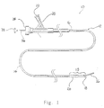
- FIG. 1 shows a catheter assembly 10 constructed according to one embodiment of the present invention.
- Catheter assembly 10 includes a catheter 12 composed of a flexible, thin walled body or tube 14 having an inner lumen (not shown) extending between proximal and distal catheter ends 16,18 respectively.
- Tube 14 may be made from any medically acceptable material, preferrably a nondistensible polymer having the appropriate mechanical properties. Preferred materials include polyethylene, polyester, polypropylene, polyimide, polyvinyl chloride, ethylvinyl acetate, polyethylene terephthalate, polyurethane, PEBAX. fluoropolymers, and their mixtures and block or random copolymers.
- Tube 14 may be a single layer construction or a multiple layer composite construction.
- Tube 14 may have a spiral wound construction, as shown in U.S. Patent No. 5,658,264, or a braided construction, as shown in co-pending U.S. Patent Application Serial No. 08/607,847, titled "BRAIDED BODY BALLOON CATHETER".
- the proximal catheter end 16 is provided with a syringe fitting 20 through which fluid can be supplied to the catheter lumen through a port 22 .
- the fitting includes an axially extending port 24 also communicating with the catheter's inner lumen.
- Tube 14 preferably has an inner diameter of approximately 0.000254-1.524 mm (0.010-60 mils) and walls that are approximately 0.0762-0.381 mm (3-15 mils) thick. The total tube length is preferably between about 50-300 cm.
- the catheter of Figure I is shown with an optional elongate torqueable guidewire 36 which is constructed to extend through the catheter for axial sliding therein.
- Optional guidewire 36 may have any suitable construction for guiding the flexible catheter to its intended site within the body.
- the length of the guidewire is at least about 10-50 cm longer than the catheter such that the distal end of the guidewire can be extended several centimeters or more beyond the distal end of the catheter, while allowing the proximal end of the wire to be manipulated, such as by torqueing.
- the proximal end of the guidewire is equipped with a handle 38 for applying torque to the wire during a catheter operation.
- the guidewire may have a variable or step diameter along its length, typically including a larger-diameter, stiffer proximal region, and one or more smaller-diameter, more flexible distal end regions, giving the wire good torqueability in its more proximal region, and better flexibility and maneuverability along its more distal region where the wire is advanced along smaller-diameter tortuous pathways.
- Typical wire dimensions, for a catheter having a lumen diameter of between about 0.51-1.27 mm (20-50 mils), are a proximal segment extending along all but the last 20-50 cm of wire and having a diameter of between about 0.46-1.02 mm (18-40 mils), and one or more reduced diameter segments 20-50 cm in length having diameters of between about 0.2-0.46 mm (8-18 mils).
- the distal end portion of the wire may have a substantially constant taper, down to a final wire thickness of about 0.0254-0.127 mm (1-5 mils) for greater distal-end flexibility. This tapered region may be encased in a constant-diameter coil and may terminate in a bent tip to facilitate steering through the vasculature.
- the distal end region 15 of catheter 12 is provided with an inflatable balloon 26 .
- balloon 26 when inflated in position, aids in controlling the placement of vaso-occlusive materials or devices by blocking the entrance to the aneurysm.
- the balloon is preferably about 0.5 to 3 cm in length, and has a wall section which can be inflated by fluid supplied through the catheter lumen when the distal end of the catheter tube is partially blocked in a manner to be described below.
- the balloon wall section is preferably formed from a thin sleeve of polymeric material and attached at its opposite sleeve ends to relatively more rigid tube sections. Details of the construction of exemplar balloons may be found in co-owned U.S. Patent Nos. 5,171,221 and 5,135,494.
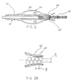
- FIGS 2 through 4 illustrate various constructions of the distal end region 15 and balloon 26 of the catheter illustrated in Figure 1 for the controlled delivery of vaso-occlusive materials or devices.
- catheter tube 52 has an inflatable balloon 54 which is formed by an inflatable sleeve 56 secured at its ends to the catheter wall.
- the balloon sleeve may be formed of a thin polymer material, and preferably an elastomeric, stretchable material such as silicone rubber, latex rubber, or polyvinyl chloride, or alternatively, a non-stretchable film material such as polyethylene or polypropylene. Attachment of the sleeve ends to the catheter tube is by gluing, heat sealing or the like, or other known methods.
- One advantage of an elastomeric sleeve is that it tends to remain flush with the tube in an uninflated state, and also tends to deflate itself when the fluid pressure is released.
- Non-stretchable materials may be preferred in some instances because they require less pressure to inflate.
- At least one opening 60 is formed in the catheter tube 52 to provide for fluid communication between the catheter lumen 61 and the balloon 54 .
- Distal to opening 60 is constricted region 63 of catheter tube 52 .
- pusher 66 discharges vaso-occlusive coil 65 from the catheter lumen 61
- coil 65 passes through constricted region 63 to at least partially or completely block catheter lumen 61 .
- any fluid pressure supplied by way of port 22 is communicated to balloon 54 by way of opening 60 . thus inflating the balloon.
- This construction provides for a single lumen catheter having a valve which is inflated simultaneously with delivery of the vaso-occlusive implant to the aneurysm.
- the inside surface of catheter tube 52 provides a suitable guide for the delivery of vaso-occlusive implants such as coils using a suitable pusher.
- the inside diameter of catheter tube 52 in the region before constricted region 63 is generally somewhat larger than that of the expected coil outside diameter.
- the inside diameter in that area may be oversized 0.051 to 0.635 mm (0.002 to 0.025 inches) or more, preferably about 0.127 mm (0.005 inches) to about 0.254 mm (0.010 inches).
- Constricted region 63 may be constructed to be significantly smaller than the outsided diameter of the vaso-occlusive coil or may be designed to be a close fit. Constricted region 63 typically has a region with an inside diameter which is slightly smaller than the outside diameter of the coil. For example, in a vaso-occlusive coil having an outside diameter of 0.381 mm (0.015 inches), the inside diameter of constricted region 63 is between about 0.254 to 0.381 mm (0.01 to 0.015 inches), preferably about 0.33 mm (0.013 inches).
- the inside diameter of the constricted region 63 is sized to be from about 0.178 to 0.254 mm (0.007 to 0.010 inches), preferably about 0.229 mm (0.009 inches).
- the wall of the catheter tube in that area is flexible enough to allow the coils to pass through without requiring excessively high axial discharge forces from the pusher, and yet maintain a seal sufficient to facilitate inflation of the balloon.
- the vaso-occlusive coil may be constructed such that the axial pitch, p 1 between successive coils 69 are substantially the same as the wire diameter of the coils 69 . Some amount of deviation is acceptable, however, because the axial forces required for discharge of the coil 65 through the constricted region 63 will compress the coils together essentially as shown. Although not necessarily required, sealing may also be improved if the radial pitch, p2 is close to the same as the wire diameter as shown.
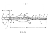
- FIG. 3 shows a further embodiment of the inventive catheter.
- the catheter again has a catheter tube 52 and an inflatable balloon 54 which is formed by an inflatable sleeve 56 secured at its ends to the catheter wall in the manner described above with reference to Figure 2.
- a lengthened distal section 72 is provided distal of balloon 54. At least a portion, or preferably substantially all, of distal section 72 is constricted such that the inside diameter of the catheter tube 52 in the region of distal section 72 cooperates with the outside diameter of vaso-occlusive coil 65 as it is discharged by pusher 66.
- pusher 66 may be of any suitable type adapted to discharge and release coil 65 .
- inventive catheter or the present invention has been described with reference to a wire type pusher, it should be appreciated that many other types of discharge devices, such as those described above, may be suitable for use with the present invention.
- Other types of discharge devices such as the hydraulic delivery described U.S. Patent No. 5,669,931 to Kupiecki et al. are believed to be particularly suited for use with the present invention.
- Lengthened distal section 72 is preferably heat shapeable, for instance using a shaping mandrel and steam as is known in the art.
- the distal section 72 may be given any desired shape by the operating surgeon to optimize steerability for accessing the delivery site or for optimizing the fill of the aneurysm by the vaso-occlusive coil or coils.
- it may be desirable to shape the area of the catheter tube 52 in the area of the inflatable balloon 54 to facilitate optimum positioning of the balloon.
- distal section 72 extends through the opening at aneurysm neck 82 and into the aneurysm sac. As shown, distal section may be advantageously shaped to optimally fill the aneurysm according to the surgeon's preference and experience.
- the balloon is positioned such that upon inflation, it blocks the opening of the aneurysm neck 82 to ensure that the discharged coils are contained within aneurysm sac 80 and do not escape to either the of the intersection body lumen 84, 86 .
- the balloon is automatically inflated as the coil 65 is discharged as coil 65 cooperates with the constricted portion of the distal section 72 to seal off the catheter lumen distal of balloon 54. As coil 65 passes out of distal section 72 and completely in the aneurysm sac 80. the balloon is automatically deflated as the catheter is no longer blocked or sealed.
- catheter tube 52 is provided with a number of variable markers both proximal to and distal to the balloon 54 .
- Lengthened distal section 72 is provided with number of spaced radioopaque markers 73, 75, 77, 79 , and 80.
- each distal marker has a corresponding proximal marker positioned proximally at a distance, d .
- proximal marker 74 is at a distance, d from distal marker 73
- proximal marker 76 is at a distance, d from distal marker 75
- proximal marker 78 is at a distance, d from distal marker 77
- Balloon markers 80, 88 may be provided to indicate the position of the balloon during the operating procedure.
- Pusher 66 may also be provided with tip marker 83 at its distal tip and a tail marker 98 proximally located at a distance, d which as described above corresponds to the length of the coil to be discharged.
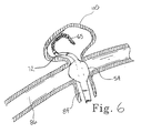
- the marker pairs allow the lengthened distal section 72 to be cut to a shorter length to accommodate the operating surgeon's preference. For instance, it may be desirable to have a shortened distal section 72 when accessing and treating a relatively smaller aneurysm site such as aneurysm 110 as shown in Figure 6. In that case, distal section 72 is cut back, preferably in such a manner as to place one of the distal variable markers at or near the cut tip.
- the marker pair to be used would be distal marker 73 and proximal marker 74.
- Distal marker 73 is especially useful as the catheter is accessing the vasculature in route to and entering the delivery site or aneurysm.
- a coil is loaded into the proximal end of the catheter at port 24 ( Figure 1) and advanced through the catheter distally by pusher 66. its proper position prior to discharge may be appreciated by aligning each end of coil 65 with the respective distal and proximal markers 73, 74 as shown in Figure 3.
- Proximal marker 74 may be used to determine the position of the coil. For instance, when tip marker 83 is aligned with proximal marker 74. the coil is in place to be discharged as shown in Figure 3. When pusher 66 has been advanced until tail marker 98 is aligned with proximal marker 74 then. by virtue of the spacing of the markers, it can be determined that the coil has been fully discharged by pusher 66 and no further advancement of pusher 66 is necessary. This same procedure may be employed with any of the variable marker pairs as necessitated because the length of distal section 72 has been cut. For example, if distal section 72 is cut at location 94, distal marker 77 would be used in conjunction with proximal marker 78 in the same manner as just described with reference to marker pair 73,74 .
- lengthened distal section 72 has a length of about 0.50 cm to about 3.0 cm or more.
- the length of distal section 72 is about 1.0 cm to 2.0 cm.
- Distal markers are typically radioopaque wires or bands made from gold, tungsten, platinum, alloys of these materials, or other suitable radioopaque materials typically having a width of about 0.10 mm to about 0.50 mm.
- the distal markers may be placed at increments of about 2 mm to 10 mm or more, preferably about 3 mm to 7 mm.
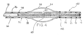
- Lengthened distal section 150 is constructed similar to that of distal section 72 except that the lumen is constricted only in the location of constricting band 155.
- Constricting band 155 is preferably a metal band positioned over the catheter tube and held in place by heat bonding, gluing, or any number of other suitable techniques.
- This contruction allows a substantial portion of the distal section 150 to be radially unrestricted, thus reducing the axial force required to discharge the vaso-occlusive coil.
- inventive aspects of the catheter described in detail above are not limited solely to the treatment of terminal aneurysms as shown in the prior figures.
- Such devices as have been described have utility at a number of vascular sites including, but not limited to, vascular malformations, fistulas, and other types of aneurysms.
- Figure 7, for example illustrates the use of the present invention with respect to berry aneurysm 120 extending from body lumen 122 .
- Lengthened distal section 72 extends through the opening at the neck 124 , but is biased against the side as shown. In this position, balloon 54 is inflated as coil 65 passes through the constricted section of lengthened section 72 and is able to adequately contain coil 65 within the aneurysm.
Abstract
Description
- This invention is in the general field of surgical instruments and relates specifically to a single lumen valved balloon catheter for delivering occlusive implants to a desired site in a mammal.
- Endovascular therapy has been used to treat a variety of different conditions, including control of internal bleeding, occlusion of blood supply to tumors, and relief of vessel wall pressure in the region of an aneurysm. Such therapeutic treatments typically require the use of a catheter to place various treatment materials, devices, and drugs at remote locations within the body. Microcatheters, such as those shown by Engleson. "Catheter Guidewire", U.S. Patent No. 4,884,579 and as described in Engleson. "Catheter for Guidewire Tracking", U.S. Patent No. 4.739.768. allow navigation through the body's tortuous vasculature to access such remote sites as the liver or the cerebral arteries of the brain.
- For certain maladies, such as vascular malformations and aneurysms, it may be required to create an endovascular occlusion at the defect site. A catheter is typically used to place a vaso-occlusive device or agent within the vasculature of the body to either block the flow of blood through a vessel making up that portion of the vasculature by forming an embolus or by forming such an embolus within an aneurysm stemming from the vessel. In the case of an aneurysm in a parent vessel or artery, for example, the distal end of a delivery catheter is placed within the aneurysm and a suitable vaso-occlusion material or device is delivered through the distal end of the catheter and into the aneurysm, thus forming the desired embolus.
- Formation of the embolus may involve the injection of a fluid embolic agent such as microfibrillar collagen. Silastic beads, or polymeric resins such as cyanoacrylate. Ideally, the embolizing agent adapts itself to the irregular shape of the internal walls of the malformation or aneurysm. One risk with this procedure is inadvertent embolism in the parent artery due to the inability to contain the fluid agent within the aneurysm. This is especially true when the opening to the aneurysm is relatively large.
- Mechanical vaso-occlusive devices are also well known. One widely used vaso-occlusive device is a wire coil or braid which can be introduced through a delivery catheter in a stretched linear form and which assumes an irregular shape upon discharge of the device from the end of the catheter to engage and fill an opening such as an aneurysm.
- For instance, U.S. Patent No. 4,994,069 to Ritchart et al., shows a flexible, preferably coiled, wire for use in a small vessel vaso-occlusion. Ritchart teaches a coil which is fairly soft that may be delivered to the site using a catheter and pusher. The catheter may be guided to the site through the use of a guidewire (see U.S. Patent No. 4.884.579) or by flow-directed means such as a balloon placed at the distal end of the catheter. Once the site has been reached, the catheter lumen is cleared by removing the guidewire (if a guidewire has been used), and one or more coils are placed into the proximal open end of the catheter and advanced through the catheter with a pusher. The pusher is typically a wire having a distal end adapted to engage and push the coil through the catheter lumen as the pusher itself is advanced through the catheter. Once the coil reaches the distal end of the catheter, it is discharged from the catheter by the pusher into the vascular site.
- The Ritchart et al, coils are typically pushed into the desired vascular site in a linear configuration. Upon discharge from the catheter, the coil may undertake any of a number of random or regular configurations designed to till the site. The coils are relatively permanent, can be easily imaged radiographically, and may be retrieved.
- In addition to using a pusher as described in Ritchart, the vaso-occlusive coils may be discharged from the catheter in a variety of other ways. U.S. Patent Nos. 5,354,295 and 5,122,136, both to Guglielmi et al., describe an electrolytically detachable embolic device. U.S Patent No. 5,234,437, to Sepetka, shows a method of unscrewing a helically wound coil from a pusher having interlocking surfaces. U.S. Patent No. 5,250,071, to Palermo, shows an embolic coil assemby using interlocking clasps mounted both on the pusher and on the embolic coil. U.S. Patent No. 5.261,916, to Engelson, shows a detachable pusher-vaso-occlusive coil assembly having an interlocking ball and keyway-type coupling. U.S. Patent No. 5,304,195, to Twyford et al.. shows a pusher-vaso-occlusive coil assembly having an affixed, proximately extending wire carrying a ball on its proximal end and a pusher having a similar end. The two ends are interlocked and disengage when expelled from the distal tip of the catheter. U.S. Patent No. 5,312,415, to Palermo, also shows a method for discharging numerous coils from a single pusher by use of a guidewire which has a section capable of interconnecting with the interior of the helically wound coil. U.S. Patent No. 5,350,397, to Palermo et al., shows a pusher having a throat at its distal end and a pusher through its axis. The pusher sheath will hold onto the end of an embolic coil and will then be released upon pushing the axially placed pusher wire against the member found-on the proximal end of the vaso-occlusive coil. Finally, U.S Patent No. 5,669.931 shows hydraulic discharge of embolic coils. In a preferred embodiment, the coils are provided in an introducer cartridge.
- Regardless of the manner of discharge, many embolic coils are subject to the same placement risk as that of fluid embolic agents. That is, as the length of coil is discharged from the distal end of the catheter into an aneurysm, for example, it is difficult to ensure that the coil is contained within the open space of the aneurysm. For example, the distal end or an intermediate section of the discharged coil may be deflected or routed back through the opening to the aneurysm as the coil proceeds to conform to and fill the open space within the aneurysm.
- There is a need for a delivery system which overcomes the limitations described above. More specifically, there is a need for a catheter for delivering vaso-occlusive materials or devices which can control the placement of the materials or devices upon discharge from the catheter. The delivery catheter must have a small diameter and have a highly flexible construction which permits movement along a small-diameter, tortuous vessel path.
- EP-A-0 664 104 discloses an arrangement in accordance with the precharacterising section of claim 1.
- According to the present invention there is provided a catheter assembly for delivering a vaso-occlusive member, comprising:
- a catheter having an inner lumen extending between proximal and distal ends of the catheter, the lumen having a first inner diameter for the receipt and the axial sliding therein of a vaso-occlusive member, an inflatable balloon disposed adjacent the distal end and in fluid communication with the lumen, and a tip section extending distally from the balloon to the distal end, the lumen in at least a portion of said tip section having a second inner diameter;
- The inside diameter of the lumen in the area of the tip section is preferably less than the outside diameter of the vaso-occlusive member. In a preferred embodiment, the inner diameter is about 0.025-0.076 mm (0.001 to 0.003 inches) smaller than the outer diameter of the vaso-occlusive member. A decreased diameter in the tip area may be created using an annular band positioned around the exterior of the tip section. When the inside diameter of the tip section is configured to be smaller than the outside diameter of the vaso-occlusive member, it may be preferable to construct the tip to be sufficiently flexible to allow the vaso-occlusive coil to be discharged without requiring excessive axial force.
- The tip section may typically have a length greater than 1 cm and may be cut or trimmed to yield the desired length depending on the preference of the operating surgeon. The tip section may be shapeable, for instance using steam.
-
- Figure 1 shows a catheter device constructed according to one embodiment of the present invention.
- Figure 2 shows a partial cross-sectional view of one embodiment of the distal region of the inventive catheter.
- Figure 2A shows a detail view of the constricted region as indicated by view line 2A-2A in Figure 2.
- Figure 3 shows a partial cross-sectional view of an further embodiment of the distal region of the inventive catheter..
- Figure 4 shows a partial cross-sectional view of an alternate construction of the distal region of the inventive catheter.
- Figure 5 is an illustration of the inventive catheter during operation at the site of a terminal aneurysm.
- Figure 6 is an illustration of the inventive catheter after sizing an in use at the site of a smaller terminal aneurysm.
- Figure 7 is an illustration of the inventive catheter at the site of a berry aneurysm.
- Referring to the drawings in detail wherein like numerals indicate like elements, the present invention generally involves a catheter for the controlled delivery or discharge or vaso-occlusive materials or implants. The placement of the implant is controlled by way of a single-lumen valved balloon catheter. According to the present invention, the catheter may have a shapeable section distal to the balloon and radioopaque markers positioned to provide improved visualization of the implant during delivery.
- Figure 1 shows a
catheter assembly 10 constructed according to one embodiment of the present invention.Catheter assembly 10 includes acatheter 12 composed of a flexible, thin walled body ortube 14 having an inner lumen (not shown) extending between proximal and distal catheter ends 16,18 respectively.Tube 14 may be made from any medically acceptable material, preferrably a nondistensible polymer having the appropriate mechanical properties. Preferred materials include polyethylene, polyester, polypropylene, polyimide, polyvinyl chloride, ethylvinyl acetate, polyethylene terephthalate, polyurethane, PEBAX. fluoropolymers, and their mixtures and block or random copolymers.Tube 14 may be a single layer construction or a multiple layer composite construction.Tube 14 may have a spiral wound construction, as shown in U.S. Patent No. 5,658,264, or a braided construction, as shown in co-pending U.S. Patent Application Serial No. 08/607,847, titled "BRAIDED BODY BALLOON CATHETER". - The proximal catheter end 16 is provided with a syringe fitting 20 through which fluid can be supplied to the catheter lumen through a
port 22. The fitting includes anaxially extending port 24 also communicating with the catheter's inner lumen.Tube 14 preferably has an inner diameter of approximately 0.000254-1.524 mm (0.010-60 mils) and walls that are approximately 0.0762-0.381 mm (3-15 mils) thick. The total tube length is preferably between about 50-300 cm. - The catheter of Figure I is shown with an optional elongate torqueable guidewire 36 which is constructed to extend through the catheter for axial sliding therein.
Optional guidewire 36 may have any suitable construction for guiding the flexible catheter to its intended site within the body. Typically, the length of the guidewire is at least about 10-50 cm longer than the catheter such that the distal end of the guidewire can be extended several centimeters or more beyond the distal end of the catheter, while allowing the proximal end of the wire to be manipulated, such as by torqueing. The proximal end of the guidewire is equipped with ahandle 38 for applying torque to the wire during a catheter operation. - The guidewire may have a variable or step diameter along its length, typically including a larger-diameter, stiffer proximal region, and one or more smaller-diameter, more flexible distal end regions, giving the wire good torqueability in its more proximal region, and better flexibility and maneuverability along its more distal region where the wire is advanced along smaller-diameter tortuous pathways. Typical wire dimensions, for a catheter having a lumen diameter of between about 0.51-1.27 mm (20-50 mils), are a proximal segment extending along all but the last 20-50 cm of wire and having a diameter of between about 0.46-1.02 mm (18-40 mils), and one or more reduced diameter segments 20-50 cm in length having diameters of between about 0.2-0.46 mm (8-18 mils). In addition, the distal end portion of the wire may have a substantially constant taper, down to a final wire thickness of about 0.0254-0.127 mm (1-5 mils) for greater distal-end flexibility. This tapered region may be encased in a constant-diameter coil and may terminate in a bent tip to facilitate steering through the vasculature.
- The
distal end region 15 ofcatheter 12 is provided with aninflatable balloon 26. According to one aspect of the present invention,balloon 26, when inflated in position, aids in controlling the placement of vaso-occlusive materials or devices by blocking the entrance to the aneurysm. The balloon is preferably about 0.5 to 3 cm in length, and has a wall section which can be inflated by fluid supplied through the catheter lumen when the distal end of the catheter tube is partially blocked in a manner to be described below. The balloon wall section is preferably formed from a thin sleeve of polymeric material and attached at its opposite sleeve ends to relatively more rigid tube sections. Details of the construction of exemplar balloons may be found in co-owned U.S. Patent Nos. 5,171,221 and 5,135,494. - Figures 2 through 4 illustrate various constructions of the
distal end region 15 andballoon 26 of the catheter illustrated in Figure 1 for the controlled delivery of vaso-occlusive materials or devices. Referring to Figure 2,catheter tube 52 has aninflatable balloon 54 which is formed by aninflatable sleeve 56 secured at its ends to the catheter wall. The balloon sleeve may be formed of a thin polymer material, and preferably an elastomeric, stretchable material such as silicone rubber, latex rubber, or polyvinyl chloride, or alternatively, a non-stretchable film material such as polyethylene or polypropylene. Attachment of the sleeve ends to the catheter tube is by gluing, heat sealing or the like, or other known methods. One advantage of an elastomeric sleeve is that it tends to remain flush with the tube in an uninflated state, and also tends to deflate itself when the fluid pressure is released. Non-stretchable materials may be preferred in some instances because they require less pressure to inflate. - At least one
opening 60 is formed in thecatheter tube 52 to provide for fluid communication between thecatheter lumen 61 and theballoon 54. Distal toopening 60, is constrictedregion 63 ofcatheter tube 52. Aspusher 66 discharges vaso-occlusive coil 65 from thecatheter lumen 61,coil 65 passes through constrictedregion 63 to at least partially or completely blockcatheter lumen 61. Whencatheter lumen 63 is blocked, any fluid pressure supplied by way ofport 22 is communicated to balloon 54 by way ofopening 60. thus inflating the balloon. This construction provides for a single lumen catheter having a valve which is inflated simultaneously with delivery of the vaso-occlusive implant to the aneurysm. - The inside surface of
catheter tube 52 provides a suitable guide for the delivery of vaso-occlusive implants such as coils using a suitable pusher. The inside diameter ofcatheter tube 52 in the region before constrictedregion 63 is generally somewhat larger than that of the expected coil outside diameter. For example the inside diameter in that area may be oversized 0.051 to 0.635 mm (0.002 to 0.025 inches) or more, preferably about 0.127 mm (0.005 inches) to about 0.254 mm (0.010 inches). -
Constricted region 63 may be constructed to be significantly smaller than the outsided diameter of the vaso-occlusive coil or may be designed to be a close fit.Constricted region 63 typically has a region with an inside diameter which is slightly smaller than the outside diameter of the coil. For example, in a vaso-occlusive coil having an outside diameter of 0.381 mm (0.015 inches), the inside diameter of constrictedregion 63 is between about 0.254 to 0.381 mm (0.01 to 0.015 inches), preferably about 0.33 mm (0.013 inches). For a vaso-occlusive coil having an outside diameter of 0.254 mm (0.010 inches), the inside diameter of the constrictedregion 63 is sized to be from about 0.178 to 0.254 mm (0.007 to 0.010 inches), preferably about 0.229 mm (0.009 inches). - Preferably, the wall of the catheter tube in that area is flexible enough to allow the coils to pass through without requiring excessively high axial discharge forces from the pusher, and yet maintain a seal sufficient to facilitate inflation of the balloon. As seen in Figure 2A, the vaso-occlusive coil may be constructed such that the axial pitch, p1 between
successive coils 69 are substantially the same as the wire diameter of thecoils 69. Some amount of deviation is acceptable, however, because the axial forces required for discharge of thecoil 65 through the constrictedregion 63 will compress the coils together essentially as shown. Although not necessarily required, sealing may also be improved if the radial pitch, p2 is close to the same as the wire diameter as shown. - Figure 3 shows a further embodiment of the inventive catheter. The catheter again has a
catheter tube 52 and aninflatable balloon 54 which is formed by aninflatable sleeve 56 secured at its ends to the catheter wall in the manner described above with reference to Figure 2. According to one aspect of the present invention, a lengtheneddistal section 72 is provided distal ofballoon 54. At least a portion, or preferably substantially all, ofdistal section 72 is constricted such that the inside diameter of thecatheter tube 52 in the region ofdistal section 72 cooperates with the outside diameter of vaso-occlusive coil 65 as it is discharged bypusher 66. - Again,
pusher 66 may be of any suitable type adapted to discharge andrelease coil 65. Although the inventive catheter or the present invention has been described with reference to a wire type pusher, it should be appreciated that many other types of discharge devices, such as those described above, may be suitable for use with the present invention. Other types of discharge devices such as the hydraulic delivery described U.S. Patent No. 5,669,931 to Kupiecki et al. are believed to be particularly suited for use with the present invention. - Lengthened
distal section 72 is preferably heat shapeable, for instance using a shaping mandrel and steam as is known in the art. In this manner, thedistal section 72 may be given any desired shape by the operating surgeon to optimize steerability for accessing the delivery site or for optimizing the fill of the aneurysm by the vaso-occlusive coil or coils. In this same manner, it may be desirable to shape the area of thecatheter tube 52 in the area of theinflatable balloon 54 to facilitate optimum positioning of the balloon. - Referring now to Figure 5, having a lengthened distal section is particularly useful when treating an aneurysm, such as a terminal aneurysm as shown at the intersection of
terminal body lumen 84 and intersectingbody lumen 86. The catheter of Figure 3 is shown in place for delivering vaso-occlusive coil 65 withaneurysm sac 80.Distal section 72 extends through the opening ataneurysm neck 82 and into the aneurysm sac. As shown, distal section may be advantageously shaped to optimally fill the aneurysm according to the surgeon's preference and experience. - The balloon is positioned such that upon inflation, it blocks the opening of the
aneurysm neck 82 to ensure that the discharged coils are contained withinaneurysm sac 80 and do not escape to either the of theintersection body lumen coil 65 is discharged ascoil 65 cooperates with the constricted portion of thedistal section 72 to seal off the catheter lumen distal ofballoon 54. Ascoil 65 passes out ofdistal section 72 and completely in theaneurysm sac 80. the balloon is automatically deflated as the catheter is no longer blocked or sealed. - Referring again to Figure 3. another aspect of the present invention involving improved radioopaque markers is illustrated. According to this aspect of the present invention,
catheter tube 52 is provided with a number of variable markers both proximal to and distal to theballoon 54. Lengtheneddistal section 72 is provided with number of spacedradioopaque markers occlusive coil 65 having a length, d, each distal marker has a corresponding proximal marker positioned proximally at a distance, d. For instance,proximal marker 74 is at a distance, d fromdistal marker 73,proximal marker 76 is at a distance, d fromdistal marker 75,proximal marker 78 is at a distance, d fromdistal marker 77, and so on with each variable marker pair spaced at a distance corresponding to the length of the coil to be delivered.Balloon markers Pusher 66 may also be provided withtip marker 83 at its distal tip and a tail marker 98 proximally located at a distance, d which as described above corresponds to the length of the coil to be discharged. - Typically, only one of the variable marker pairs will be used for a given surgical procedure. However, the marker pairs allow the lengthened
distal section 72 to be cut to a shorter length to accommodate the operating surgeon's preference. For instance, it may be desirable to have a shorteneddistal section 72 when accessing and treating a relatively smaller aneurysm site such asaneurysm 110 as shown in Figure 6. In that case,distal section 72 is cut back, preferably in such a manner as to place one of the distal variable markers at or near the cut tip. - With the
distal section 72 as shown in Figure 3, the marker pair to be used would bedistal marker 73 andproximal marker 74.Distal marker 73 is especially useful as the catheter is accessing the vasculature in route to and entering the delivery site or aneurysm. As a coil is loaded into the proximal end of the catheter at port 24 (Figure 1) and advanced through the catheter distally bypusher 66. its proper position prior to discharge may be appreciated by aligning each end ofcoil 65 with the respective distal andproximal markers - Once treatment of the aneurysm has begun by discharging coils into the aneurysm sac, it often becomes difficult to see
distal marker 73.Proximal marker 74 may be used to determine the position of the coil. For instance, whentip marker 83 is aligned withproximal marker 74. the coil is in place to be discharged as shown in Figure 3. Whenpusher 66 has been advanced until tail marker 98 is aligned withproximal marker 74 then. by virtue of the spacing of the markers, it can be determined that the coil has been fully discharged bypusher 66 and no further advancement ofpusher 66 is necessary. This same procedure may be employed with any of the variable marker pairs as necessitated because the length ofdistal section 72 has been cut. For example, ifdistal section 72 is cut atlocation 94,distal marker 77 would be used in conjunction withproximal marker 78 in the same manner as just described with reference tomarker pair - In a preferred embodiment lengthened
distal section 72 has a length of about 0.50 cm to about 3.0 cm or more. Preferably, the length ofdistal section 72 is about 1.0 cm to 2.0 cm. Distal markers are typically radioopaque wires or bands made from gold, tungsten, platinum, alloys of these materials, or other suitable radioopaque materials typically having a width of about 0.10 mm to about 0.50 mm. The distal markers may be placed at increments of about 2 mm to 10 mm or more, preferably about 3 mm to 7 mm. - An alternate construction of lengthened distal section is shown in Figure 4. In some instances, having a restricted section the full length of
distal section 72 of the previous figures may result in too much friction for the delivery of very soft coils or coils whose secondary shape would tend to make them bind in such a lengthened constriction. Lengtheneddistal section 150, as shown in Figure 4, is constructed similar to that ofdistal section 72 except that the lumen is constricted only in the location of constrictingband 155.Constricting band 155 is preferably a metal band positioned over the catheter tube and held in place by heat bonding, gluing, or any number of other suitable techniques. This contruction allows a substantial portion of thedistal section 150 to be radially unrestricted, thus reducing the axial force required to discharge the vaso-occlusive coil. With this construction, it may be optionally desirable to construct the distal end of the pusher (for a length equal to the length of distal section 150) with a sufficiently large diameter to engage the constriction at theband 155 so that the balloon remains inflated until thecoil 65 exits the end of the catheter (otherwise the balloon deflates after the coil passes band 155 but is not yet fully discharged.). - The inventive aspects of the catheter described in detail above are not limited solely to the treatment of terminal aneurysms as shown in the prior figures. Such devices as have been described have utility at a number of vascular sites including, but not limited to, vascular malformations, fistulas, and other types of aneurysms. Figure 7, for example illustrates the use of the present invention with respect to
berry aneurysm 120 extending frombody lumen 122. Lengtheneddistal section 72 extends through the opening at the neck 124, but is biased against the side as shown. In this position,balloon 54 is inflated ascoil 65 passes through the constricted section of lengthenedsection 72 and is able to adequately containcoil 65 within the aneurysm. - Modification of the above-described variations of carrying out the invention that would be apparent to those of skill in the fields of medical device design generally, and vaso-occlusive delivery devices specifically, are intended to be within the scope of the following claims.
Claims (12)
- A catheter assembly (10) for delivering a vaso-occlusive member (65), comprising:a catheter (12) having an inner lumen (61) extending between proximal and distal ends (16, 18) of the catheter (12), the lumen (61) having a first inner diameter for the receipt and the axial sliding therein of a vaso-occlusive member (65), an inflatable balloon (26, 54) disposed adjacent the distal end (18) and in fluid communication with the lumen (61), and a tip section (72, 150) extending distally from the balloon to the distal end (18), the lumen in at least a portion of said tip section having a second inner diameter;characterized in that the second inner diameter is less than the first inner diameter so as to cause the second inner diameter of said portion of the tip section to engage the outside diameter of the vaso-occlusive member as it is delivered through the tip section so as at least partially to block said lumen so that fluid supplied through said lumen will be forced into the balloon to inflate the balloon.
- The catheter assembly (10) of claim 1, wherein the tip section (72, 150) is shapeable.
- The catheter assembly (10) of claim 1, wherein the tip section (72, 150) further comprises a plurality of spaced radioopaque markers (73, 75, 77).
- The catheter assembly (10) of claim 3, further comprising a respective proximal marker (74, 76, 78) for each of the spaced markers (73, 75, 77), each of the proximal markers (74, 76, 78) spaced from a respective spaced marker (73, 75, 77) by a distance substantially equal to the length of the vaso-occlusive member (65).
- The catheter assembly (10) of claim 4, further comprising a pusher wire (66) having a distal end detachably coupled to a vaso-occlusive member (65), the pusher wire (66) being axially slidable within the inner catheter lumen (61) and having a radioopaque marker (98) located at a distance from the pusher wire distal end substantially equal to a length of the vaso-occlusive member (65).
- The catheter assembly (10) of claim 1, wherein the tip section (72, 150) has a length greater than 1.0 centimeter.
- The catheter assembly (10) of claim 4, wherein the inner diameter of the distal portion of the lumen (61) is less than or equal to the outer diameter of the vaso-occlusive member (65).
- The catheter assembly (10) of claim 7, wherein the tip section (72, 150) is flexible.
- The catheter assembly (10) of claim 4, wherein the inner diameter of the distal portion of the lumen (61) is about 0.000645 to 0.00195 mm (.0254 to .0762 mils) less than the outer diameter of the vaso-occlusive member (65).
- The catheter assembly (10) of claim 4, wherein at least a portion of the inner diameter of the distal portion of the lumen (61) is less than the outer diameter of the vaso-occlusive member (65).
- The catheter assembly (10) of claim 1, further comprising an annular band (155) positioned around an exterior of said tip section (72, 150), the annular band (155) creating an area of decreased diameter within the catheter lumen (61) relative to its diameter in the area of the tip section (72, 150) adjacent the annular band (155).
- The catheter assembly (10) of claim 11, wherein the annular band (155) is radioopaque.
Applications Claiming Priority (3)
| Application Number | Priority Date | Filing Date | Title |
|---|---|---|---|
| US950002 | 1997-10-14 | ||
| US08/950,002 US6074407A (en) | 1997-10-14 | 1997-10-14 | Delivery catheter for occlusive implants |
| PCT/US1998/021571 WO1999018861A1 (en) | 1997-10-14 | 1998-10-13 | Delivery catheter for occlusive device |
Publications (2)
| Publication Number | Publication Date |
|---|---|
| EP1022988A1 EP1022988A1 (en) | 2000-08-02 |
| EP1022988B1 true EP1022988B1 (en) | 2006-12-06 |
Family
ID=25489817
Family Applications (1)
| Application Number | Title | Priority Date | Filing Date |
|---|---|---|---|
| EP98953436A Expired - Lifetime EP1022988B1 (en) | 1997-10-14 | 1998-10-13 | Delivery catheter for occlusive device |
Country Status (7)
| Country | Link |
|---|---|
| US (1) | US6074407A (en) |
| EP (1) | EP1022988B1 (en) |
| JP (1) | JP4170587B2 (en) |
| AU (1) | AU1081499A (en) |
| CA (1) | CA2306625A1 (en) |
| DE (1) | DE69836590T2 (en) |
| WO (1) | WO1999018861A1 (en) |
Families Citing this family (66)
| Publication number | Priority date | Publication date | Assignee | Title |
|---|---|---|---|---|
| US6080170A (en) * | 1996-07-26 | 2000-06-27 | Kensey Nash Corporation | System and method of use for revascularizing stenotic bypass grafts and other occluded blood vessels |
| US5779721A (en) | 1996-07-26 | 1998-07-14 | Kensey Nash Corporation | System and method of use for revascularizing stenotic bypass grafts and other blood vessels |
| US6830577B2 (en) * | 1996-07-26 | 2004-12-14 | Kensey Nash Corporation | System and method of use for treating occluded vessels and diseased tissue |
| US6652546B1 (en) * | 1996-07-26 | 2003-11-25 | Kensey Nash Corporation | System and method of use for revascularizing stenotic bypass grafts and other occluded blood vessels |
| US6905505B2 (en) * | 1996-07-26 | 2005-06-14 | Kensey Nash Corporation | System and method of use for agent delivery and revascularizing of grafts and vessels |
| DE69828181T2 (en) * | 1997-09-12 | 2005-12-08 | Nippon Zeon Co., Ltd. | BALLOON CATHETER |
| US20050187564A1 (en) * | 1999-12-23 | 2005-08-25 | Swaminathan Jayaraman | Occlusive coil manufacturing and delivery |
| US6790218B2 (en) | 1999-12-23 | 2004-09-14 | Swaminathan Jayaraman | Occlusive coil manufacture and delivery |
| US6544225B1 (en) * | 2000-02-29 | 2003-04-08 | Cordis Neurovascular, Inc. | Embolic coil hydraulic deployment system with purge mechanism |
| US6726700B1 (en) * | 2000-08-21 | 2004-04-27 | Counter Clockwise, Inc. | Manipulatable delivery catheter for occlusive devices |
| US6482221B1 (en) * | 2000-08-21 | 2002-11-19 | Counter Clockwise, Inc. | Manipulatable delivery catheter for occlusive devices (II) |
| US6527790B2 (en) * | 2000-12-07 | 2003-03-04 | Scimed Life Systems, Inc. | Intravascular balloon catheter for embolic coil delivery |
| US6636758B2 (en) | 2001-05-01 | 2003-10-21 | Concentric Medical, Inc. | Marker wire and process for using it |
| US6702782B2 (en) | 2001-06-26 | 2004-03-09 | Concentric Medical, Inc. | Large lumen balloon catheter |
| US6638245B2 (en) * | 2001-06-26 | 2003-10-28 | Concentric Medical, Inc. | Balloon catheter |
| WO2003030752A1 (en) * | 2001-10-12 | 2003-04-17 | Boston Scientific Limited | Catheter with piezo elements for lesion diagnostics |
| US7309345B2 (en) * | 2003-07-25 | 2007-12-18 | Boston Scientific-Scimed, Inc. | Method and system for delivering an implant utilizing a lumen reducing member |
| US8060207B2 (en) | 2003-12-22 | 2011-11-15 | Boston Scientific Scimed, Inc. | Method of intravascularly delivering stimulation leads into direct contact with tissue |
| US20050137646A1 (en) * | 2003-12-22 | 2005-06-23 | Scimed Life Systems, Inc. | Method of intravascularly delivering stimulation leads into brain |
| US7295875B2 (en) | 2004-02-20 | 2007-11-13 | Boston Scientific Scimed, Inc. | Method of stimulating/sensing brain with combination of intravascularly and non-vascularly delivered leads |
| US7590454B2 (en) * | 2004-03-12 | 2009-09-15 | Boston Scientific Neuromodulation Corporation | Modular stimulation lead network |
| US7177702B2 (en) | 2004-03-12 | 2007-02-13 | Scimed Life Systems, Inc. | Collapsible/expandable electrode leads |
| US20050203600A1 (en) | 2004-03-12 | 2005-09-15 | Scimed Life Systems, Inc. | Collapsible/expandable tubular electrode leads |
| US7231260B2 (en) | 2004-05-06 | 2007-06-12 | Boston Scientific Scimed, Inc. | Intravascular self-anchoring electrode body with arcuate springs, spring loops, or arms |
| US8267985B2 (en) | 2005-05-25 | 2012-09-18 | Tyco Healthcare Group Lp | System and method for delivering and deploying an occluding device within a vessel |
| US8617234B2 (en) | 2004-05-25 | 2013-12-31 | Covidien Lp | Flexible vascular occluding device |
| CA2565106C (en) | 2004-05-25 | 2013-11-05 | Chestnut Medical Technologies, Inc. | Flexible vascular occluding device |
| US20060206200A1 (en) | 2004-05-25 | 2006-09-14 | Chestnut Medical Technologies, Inc. | Flexible vascular occluding device |
| US8628564B2 (en) | 2004-05-25 | 2014-01-14 | Covidien Lp | Methods and apparatus for luminal stenting |
| SG175723A1 (en) | 2004-05-25 | 2011-12-29 | Tyco Healthcare | Vascular stenting for aneurysms |
| US7286879B2 (en) | 2004-07-16 | 2007-10-23 | Boston Scientific Scimed, Inc. | Method of stimulating fastigium nucleus to treat neurological disorders |
| EP1793743B1 (en) | 2004-09-22 | 2009-11-18 | Dendron GmbH | Micro-spiral implantation device |
| US7879064B2 (en) | 2004-09-22 | 2011-02-01 | Micro Therapeutics, Inc. | Medical implant |
| US7937160B2 (en) * | 2004-12-10 | 2011-05-03 | Boston Scientific Neuromodulation Corporation | Methods for delivering cortical electrode leads into patient's head |
| CN101180006B (en) | 2005-05-25 | 2010-09-22 | 切斯纳特医药技术公司 | System and method for delivering and deploying and occluding device within a vessel |
| US8273101B2 (en) | 2005-05-25 | 2012-09-25 | Tyco Healthcare Group Lp | System and method for delivering and deploying an occluding device within a vessel |
| WO2007100556A1 (en) | 2006-02-22 | 2007-09-07 | Ev3 Inc. | Embolic protection systems having radiopaque filter mesh |
| JP5230602B2 (en) | 2006-04-17 | 2013-07-10 | タイコ ヘルスケア グループ リミテッド パートナーシップ | System and method for mechanically positioning an endovascular implant |
| US8777979B2 (en) | 2006-04-17 | 2014-07-15 | Covidien Lp | System and method for mechanically positioning intravascular implants |
| WO2008106480A1 (en) * | 2007-03-01 | 2008-09-04 | Boston Scientific Scimed, Inc. | Microcatheter introducer sheath |
| JP5249249B2 (en) | 2007-03-13 | 2013-07-31 | コヴィディエン リミテッド パートナーシップ | Implant including a coil and a stretch resistant member |
| KR20100015521A (en) | 2007-03-13 | 2010-02-12 | 마이크로 테라퓨틱스 인코포레이티드 | An implant, a mandrel, and a method of forming an implant |
| US20080287982A1 (en) * | 2007-05-16 | 2008-11-20 | Boston Scientific Scimed, Inc. | Catheters for electrolytically detachable embolic devices |
| US10716573B2 (en) | 2008-05-01 | 2020-07-21 | Aneuclose | Janjua aneurysm net with a resilient neck-bridging portion for occluding a cerebral aneurysm |
| US10028747B2 (en) | 2008-05-01 | 2018-07-24 | Aneuclose Llc | Coils with a series of proximally-and-distally-connected loops for occluding a cerebral aneurysm |
| US9675482B2 (en) | 2008-05-13 | 2017-06-13 | Covidien Lp | Braid implant delivery systems |
| JP5612279B2 (en) * | 2009-06-26 | 2014-10-22 | 日本合成化学工業株式会社 | Non-human animal model of myocardial infarction and production method thereof |
| US20110046657A1 (en) * | 2009-08-20 | 2011-02-24 | Boston Scientific Scimed, Inc. | Embolic Coil Introducer Catheter Locking Mechanisms |
| US9358140B1 (en) | 2009-11-18 | 2016-06-07 | Aneuclose Llc | Stent with outer member to embolize an aneurysm |
| US9017366B2 (en) * | 2011-08-19 | 2015-04-28 | Empirilon Technology, Llc | Methods and systems for performing intralumenal procedures |
| US9579104B2 (en) | 2011-11-30 | 2017-02-28 | Covidien Lp | Positioning and detaching implants |
| US9011480B2 (en) | 2012-01-20 | 2015-04-21 | Covidien Lp | Aneurysm treatment coils |
| US9687245B2 (en) | 2012-03-23 | 2017-06-27 | Covidien Lp | Occlusive devices and methods of use |
| US9155647B2 (en) | 2012-07-18 | 2015-10-13 | Covidien Lp | Methods and apparatus for luminal stenting |
| US9301831B2 (en) | 2012-10-30 | 2016-04-05 | Covidien Lp | Methods for attaining a predetermined porosity of a vascular device |
| US9452070B2 (en) | 2012-10-31 | 2016-09-27 | Covidien Lp | Methods and systems for increasing a density of a region of a vascular device |
| US9943427B2 (en) | 2012-11-06 | 2018-04-17 | Covidien Lp | Shaped occluding devices and methods of using the same |
| US9157174B2 (en) | 2013-02-05 | 2015-10-13 | Covidien Lp | Vascular device for aneurysm treatment and providing blood flow into a perforator vessel |
| JP6467129B2 (en) * | 2013-10-17 | 2019-02-06 | メディカル・イノベイション株式会社 | catheter |
| US9713475B2 (en) | 2014-04-18 | 2017-07-25 | Covidien Lp | Embolic medical devices |
| WO2015167997A1 (en) * | 2014-04-30 | 2015-11-05 | Stryker Corporation | Implant delivery system and method of use |
| KR101563172B1 (en) * | 2014-05-20 | 2015-10-27 | (주) 타우피엔유메디칼 | Tissue protective device for the cerclage annuloplasty procedure |
| WO2018061598A1 (en) * | 2016-09-30 | 2018-04-05 | 株式会社タケモリ | Catheter |
| US20180104454A1 (en) * | 2016-10-19 | 2018-04-19 | Daniel E. Walzman | Disc balloon microcatheter |
| US10786259B2 (en) * | 2018-03-30 | 2020-09-29 | DePuy Synthes Products, Inc. | Split balloon assist device and method for using the same |
| CN110946632B (en) * | 2019-11-05 | 2021-04-13 | 杭州未名信科科技有限公司 | Blood blocking device |
Family Cites Families (34)
| Publication number | Priority date | Publication date | Assignee | Title |
|---|---|---|---|---|
| US5033998A (en) * | 1984-01-20 | 1991-07-23 | Eliot Corday | Retrograde delivery of pharmacologic and diagnostic agents via venous circulation |
| JPS62261371A (en) * | 1986-05-08 | 1987-11-13 | テルモ株式会社 | Catheter |
| US4739768B2 (en) * | 1986-06-02 | 1995-10-24 | Target Therapeutics Inc | Catheter for guide-wire tracking |
| US4850960A (en) * | 1987-07-08 | 1989-07-25 | Joseph Grayzel | Diagonally tapered, bevelled tip introducing catheter and sheath and method for insertion |
| US4813934A (en) * | 1987-08-07 | 1989-03-21 | Target Therapeutics | Valved catheter device and method |
| US4884579A (en) * | 1988-04-18 | 1989-12-05 | Target Therapeutics | Catheter guide wire |
| US5135494A (en) * | 1988-08-01 | 1992-08-04 | Target Therapeutics | Valved catheter device and method |
| US4994069A (en) * | 1988-11-02 | 1991-02-19 | Target Therapeutics | Vaso-occlusion coil and method |
| US5354295A (en) * | 1990-03-13 | 1994-10-11 | Target Therapeutics, Inc. | In an endovascular electrolytically detachable wire and tip for the formation of thrombus in arteries, veins, aneurysms, vascular malformations and arteriovenous fistulas |
| US5122136A (en) * | 1990-03-13 | 1992-06-16 | The Regents Of The University Of California | Endovascular electrolytically detachable guidewire tip for the electroformation of thrombus in arteries, veins, aneurysms, vascular malformations and arteriovenous fistulas |
| US5171221A (en) * | 1991-02-05 | 1992-12-15 | Target Therapeutics | Single lumen low profile valved balloon catheter |
| CA2104121C (en) * | 1991-04-24 | 1998-12-22 | Blair D. Walker | Exchangeable integrated-wire balloon catheter |
| US5454788A (en) * | 1991-04-24 | 1995-10-03 | Baxter International Inc. | Exchangeable integrated-wire balloon catheter |
| US5795325A (en) * | 1991-07-16 | 1998-08-18 | Heartport, Inc. | Methods and apparatus for anchoring an occluding member |
| US5261916A (en) * | 1991-12-12 | 1993-11-16 | Target Therapeutics | Detachable pusher-vasoocclusive coil assembly with interlocking ball and keyway coupling |
| US5234437A (en) * | 1991-12-12 | 1993-08-10 | Target Therapeutics, Inc. | Detachable pusher-vasoocclusion coil assembly with threaded coupling |
| ATE187053T1 (en) * | 1991-12-12 | 1999-12-15 | Target Therapeutics Inc | UNCOUPLING, SLIDING, VESSEL-OCCLOSING SPIRAL WITH INTERLOCKING COUPLING ELEMENTS |
| US5324259A (en) * | 1991-12-18 | 1994-06-28 | Advanced Cardiovascular Systems, Inc. | Intravascular catheter with means to seal guidewire port |
| US5334143A (en) * | 1992-04-17 | 1994-08-02 | Carroll Brendon J | Method to remove common bile duct stones |
| US5348537A (en) * | 1992-07-15 | 1994-09-20 | Advanced Cardiovascular Systems, Inc. | Catheter with intraluminal sealing element |
| US5312415A (en) * | 1992-09-22 | 1994-05-17 | Target Therapeutics, Inc. | Assembly for placement of embolic coils using frictional placement |
| US5250071A (en) * | 1992-09-22 | 1993-10-05 | Target Therapeutics, Inc. | Detachable embolic coil assembly using interlocking clasps and method of use |
| US5350397A (en) * | 1992-11-13 | 1994-09-27 | Target Therapeutics, Inc. | Axially detachable embolic coil assembly |
| FR2696636A1 (en) * | 1992-10-13 | 1994-04-15 | Balt Sa | Temporary wire-based blocking system for blood vessel etc. - uses coiled tubular tungsten@ wire to promote localised clotting, with hollow catheter for introduction of wire to required location |
| US5304198A (en) * | 1992-11-13 | 1994-04-19 | Target Therapeutics | Single-lumen balloon catheter having a directional valve |
| US5437632A (en) * | 1993-06-02 | 1995-08-01 | Target Therapeutics, Inc. | Variable stiffness balloon catheter |
| US5795331A (en) * | 1994-01-24 | 1998-08-18 | Micro Therapeutics, Inc. | Balloon catheter for occluding aneurysms of branch vessels |
| US5429605A (en) * | 1994-01-26 | 1995-07-04 | Target Therapeutics, Inc. | Microballoon catheter |
| US5522836A (en) * | 1994-06-27 | 1996-06-04 | Target Therapeutics, Inc. | Electrolytically severable coil assembly with movable detachment point |
| US5658264A (en) * | 1994-11-10 | 1997-08-19 | Target Therapeutics, Inc. | High performance spiral-wound catheter |
| US5573508A (en) * | 1994-11-22 | 1996-11-12 | Advanced Cardiovascular Systems, Inc. | Catheter with an expandable perfusion lumen |
| ES2185746T3 (en) * | 1995-03-30 | 2003-05-01 | Boston Scient Ltd | SYSTEM FOR THE IMPLANT OF LIQUID COILS WITH SECONDARY STRUCTURE. |
| US6440097B1 (en) * | 1995-10-06 | 2002-08-27 | Target Therapeutics, Inc. | Balloon catheter with delivery side holes |
| AU733332B2 (en) * | 1996-02-02 | 2001-05-10 | Transvascular, Inc. | Methods and apparatus for blocking flow through blood vessels |
-
1997
- 1997-10-14 US US08/950,002 patent/US6074407A/en not_active Expired - Lifetime
-
1998
- 1998-10-13 AU AU10814/99A patent/AU1081499A/en not_active Abandoned
- 1998-10-13 JP JP2000515503A patent/JP4170587B2/en not_active Expired - Fee Related
- 1998-10-13 WO PCT/US1998/021571 patent/WO1999018861A1/en active IP Right Grant
- 1998-10-13 EP EP98953436A patent/EP1022988B1/en not_active Expired - Lifetime
- 1998-10-13 DE DE69836590T patent/DE69836590T2/en not_active Expired - Lifetime
- 1998-10-13 CA CA002306625A patent/CA2306625A1/en not_active Abandoned
Also Published As
| Publication number | Publication date |
|---|---|
| CA2306625A1 (en) | 1999-04-22 |
| JP4170587B2 (en) | 2008-10-22 |
| EP1022988A1 (en) | 2000-08-02 |
| JP2001519194A (en) | 2001-10-23 |
| DE69836590D1 (en) | 2007-01-18 |
| US6074407A (en) | 2000-06-13 |
| WO1999018861A1 (en) | 1999-04-22 |
| DE69836590T2 (en) | 2007-09-27 |
| AU1081499A (en) | 1999-05-03 |
Similar Documents
| Publication | Publication Date | Title |
|---|---|---|
| EP1022988B1 (en) | Delivery catheter for occlusive device | |
| US20210308422A1 (en) | Manipulatable delivery catheter for occlusive devices | |
| US6726700B1 (en) | Manipulatable delivery catheter for occlusive devices | |
| US8273073B2 (en) | Long nose manipulatable catheter | |
| US7766049B2 (en) | Balloon catheter | |
| JP3132806B2 (en) | Liquid-like coil with secondary shape | |
| US8182544B2 (en) | Method for placing a medical agent into a vessel of the body | |
| US7108708B2 (en) | Method for placing a medical agent into a vessel of the body | |
| US11850385B2 (en) | Balloon catheter | |
| MXPA06003468A (en) | Steerable balloon catheter |
Legal Events
| Date | Code | Title | Description |
|---|---|---|---|
| PUAI | Public reference made under article 153(3) epc to a published international application that has entered the european phase |
Free format text: ORIGINAL CODE: 0009012 |
|
| 17P | Request for examination filed |
Effective date: 20000509 |
|
| AK | Designated contracting states |
Kind code of ref document: A1 Designated state(s): DE FR GB IE IT NL |
|
| RAP1 | Party data changed (applicant data changed or rights of an application transferred) |
Owner name: BOSTON SCIENTIFIC LIMITED |
|
| GRAP | Despatch of communication of intention to grant a patent |
Free format text: ORIGINAL CODE: EPIDOSNIGR1 |
|
| GRAS | Grant fee paid |
Free format text: ORIGINAL CODE: EPIDOSNIGR3 |
|
| GRAA | (expected) grant |
Free format text: ORIGINAL CODE: 0009210 |
|
| RAP1 | Party data changed (applicant data changed or rights of an application transferred) |
Owner name: BOSTON SCIENTIFIC LIMITED |
|
| AK | Designated contracting states |
Kind code of ref document: B1 Designated state(s): DE FR GB IE IT NL |
|
| REG | Reference to a national code |
Ref country code: GB Ref legal event code: FG4D |
|
| REG | Reference to a national code |
Ref country code: IE Ref legal event code: FG4D |
|
| REF | Corresponds to: |
Ref document number: 69836590 Country of ref document: DE Date of ref document: 20070118 Kind code of ref document: P |
|
| ET | Fr: translation filed | ||
| PLBE | No opposition filed within time limit |
Free format text: ORIGINAL CODE: 0009261 |
|
| STAA | Information on the status of an ep patent application or granted ep patent |
Free format text: STATUS: NO OPPOSITION FILED WITHIN TIME LIMIT |
|
| 26N | No opposition filed |
Effective date: 20070907 |
|
| PGFP | Annual fee paid to national office [announced via postgrant information from national office to epo] |
Ref country code: NL Payment date: 20071219 Year of fee payment: 10 |
|
| NLV4 | Nl: lapsed or anulled due to non-payment of the annual fee |
Effective date: 20090501 |
|
| PG25 | Lapsed in a contracting state [announced via postgrant information from national office to epo] |
Ref country code: NL Free format text: LAPSE BECAUSE OF NON-PAYMENT OF DUE FEES Effective date: 20090501 |
|
| PGFP | Annual fee paid to national office [announced via postgrant information from national office to epo] |
Ref country code: GB Payment date: 20100923 Year of fee payment: 13 |
|
| PGFP | Annual fee paid to national office [announced via postgrant information from national office to epo] |
Ref country code: DE Payment date: 20101029 Year of fee payment: 13 |
|
| PGFP | Annual fee paid to national office [announced via postgrant information from national office to epo] |
Ref country code: IT Payment date: 20101019 Year of fee payment: 13 |
|
| PGFP | Annual fee paid to national office [announced via postgrant information from national office to epo] |
Ref country code: FR Payment date: 20111118 Year of fee payment: 14 Ref country code: IE Payment date: 20111025 Year of fee payment: 14 |
|
| REG | Reference to a national code |
Ref country code: GB Ref legal event code: 732E Free format text: REGISTERED BETWEEN 20121011 AND 20121017 |
|
| REG | Reference to a national code |
Ref country code: DE Ref legal event code: R081 Ref document number: 69836590 Country of ref document: DE Owner name: STRYKER NV OPERATIONS LTD., IE Free format text: FORMER OWNER: BOSTON SCIENTIFIC LTD., BARBADOS, WEST INDIES, BB Effective date: 20121129 Ref country code: DE Ref legal event code: R081 Ref document number: 69836590 Country of ref document: DE Owner name: STRYKER CORP., KALAMAZOO, US Free format text: FORMER OWNER: BOSTON SCIENTIFIC LTD., BARBADOS, WEST INDIES, BB Effective date: 20121129 Ref country code: DE Ref legal event code: R081 Ref document number: 69836590 Country of ref document: DE Owner name: STRYKER NV OPERATIONS LTD., IE Free format text: FORMER OWNER: BOSTON SCIENTIFIC LTD., BARBADOS, BB Effective date: 20121129 Ref country code: DE Ref legal event code: R081 Ref document number: 69836590 Country of ref document: DE Owner name: STRYKER CORP., US Free format text: FORMER OWNER: BOSTON SCIENTIFIC LTD., BARBADOS, BB Effective date: 20121129 |
|
| REG | Reference to a national code |
Ref country code: FR Ref legal event code: TP Owner name: STRYKER CORPORATION, US Effective date: 20130103 |
|
| GBPC | Gb: european patent ceased through non-payment of renewal fee |
Effective date: 20121013 |
|
| REG | Reference to a national code |
Ref country code: IE Ref legal event code: MM4A |
|
| REG | Reference to a national code |
Ref country code: FR Ref legal event code: ST Effective date: 20130628 |
|
| PG25 | Lapsed in a contracting state [announced via postgrant information from national office to epo] |
Ref country code: DE Free format text: LAPSE BECAUSE OF NON-PAYMENT OF DUE FEES Effective date: 20130501 Ref country code: IE Free format text: LAPSE BECAUSE OF NON-PAYMENT OF DUE FEES Effective date: 20121013 Ref country code: GB Free format text: LAPSE BECAUSE OF NON-PAYMENT OF DUE FEES Effective date: 20121013 |
|
| REG | Reference to a national code |
Ref country code: DE Ref legal event code: R119 Ref document number: 69836590 Country of ref document: DE Effective date: 20130501 |
|
| PG25 | Lapsed in a contracting state [announced via postgrant information from national office to epo] |
Ref country code: FR Free format text: LAPSE BECAUSE OF NON-PAYMENT OF DUE FEES Effective date: 20121031 Ref country code: IT Free format text: LAPSE BECAUSE OF NON-PAYMENT OF DUE FEES Effective date: 20121013 |