EP1022643A2 - Function expanding device for electronic hardware - Google Patents
Function expanding device for electronic hardware Download PDFInfo
- Publication number
- EP1022643A2 EP1022643A2 EP00300069A EP00300069A EP1022643A2 EP 1022643 A2 EP1022643 A2 EP 1022643A2 EP 00300069 A EP00300069 A EP 00300069A EP 00300069 A EP00300069 A EP 00300069A EP 1022643 A2 EP1022643 A2 EP 1022643A2
- Authority
- EP
- European Patent Office
- Prior art keywords
- electronic hardware
- connection part
- unit
- connectable
- expanding device
- Prior art date
- Legal status (The legal status is an assumption and is not a legal conclusion. Google has not performed a legal analysis and makes no representation as to the accuracy of the status listed.)
- Withdrawn
Links
Images


Classifications
-
- G—PHYSICS
- G11—INFORMATION STORAGE
- G11B—INFORMATION STORAGE BASED ON RELATIVE MOVEMENT BETWEEN RECORD CARRIER AND TRANSDUCER
- G11B33/00—Constructional parts, details or accessories not provided for in the other groups of this subclass
- G11B33/12—Disposition of constructional parts in the apparatus, e.g. of power supply, of modules
- G11B33/121—Disposition of constructional parts in the apparatus, e.g. of power supply, of modules the apparatus comprising a single recording/reproducing device
-
- G—PHYSICS
- G06—COMPUTING; CALCULATING OR COUNTING
- G06F—ELECTRIC DIGITAL DATA PROCESSING
- G06F1/00—Details not covered by groups G06F3/00 - G06F13/00 and G06F21/00
- G06F1/16—Constructional details or arrangements
- G06F1/1613—Constructional details or arrangements for portable computers
- G06F1/1632—External expansion units, e.g. docking stations
Definitions
- the present invention relates to attachments that are connectable to electronic hardware, such as a notebook personal computer (“PC”) to expand their functions.
- PC notebook personal computer
- the conventional expanding units such as a CD-ROM drive
- Those drives which are different in specification such as a CD-ROM drive and a high density floppy disc (LS-120)
- LS-120 high density floppy disc
- An attempt to expand a notebook PC with multiple functions (or specifications) would thus need a plurality of connectors accordingly, which prevents a realization of a miniature PC body.
- a conventional notebook PC cannot include multiple connectors in order to realize the miniaturization, and thus it cannot become multifunctional.
- a CPU in the PC body controls a CD-ROM drive (or a music compact disc (“CD”) drive)
- listening to a music CD arduously needs run application software that is installed in the PC body. This operation is time-consuming and not easy.
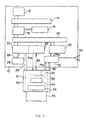
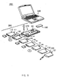
- FIG. 9 shows notebook PC related attachment group 250 and notebook PC 240.
- the notebook PC related attachment group 250 includes bay housing 270, floppy disc drive (“FDD”) 110, CD-ROM drive 130, magneto-optical (“MO " ) disc drive 140, high density floppy disc 150, digital video disk (“DVD”) drive 160, hard disc drive (“HDD”) 170, AC/DC adapter 180, and battery pack 190.
- FDD 110, CD-ROM drive 130, MO disc drive 140, high density floppy disc drive 150, DVD drive 160, and HDD 170 each constitute an expanding unit (expansion unit).
- Function expanding unit 260 for a notebook PC is made by attaching the battery pack 190 to the bay housing 270 and inserting one of the FDD 110, CD-ROM drive 130, MO disc drive 140, high density floppy disc drive 150, DVD drive 160, HDD 170 and AC/DC adapter 180. There are eight modes and its capability of extension is wider than the conventional notebook PC.
- Unit 260 is attached to the bottom of the notebook PC 240 and serves as a charger for the battery pack 190, and as a rack for the notebook PC 240.
- the notebook-PC function expanding unit 260 is attached to the notebook PC 240, the notebook PC 240 and the notebook-PC function expanding unit 260 are electrically connected to each other, expanding the function of the notebook PC 240.
- the bay housing 270 has bay 273 as a storage part.
- the bay 273 is a flat space corresponding to an outer shape of the FDD 110, etc., and has an opening into which the FDD 110 or the like is inserted.
- the above devices 110, 130, 140, 150, 160, 170 and AC/DC adapter 180 have approximately similar flat outer shapes that may be inserted into and correspond to the bay 273 in the bay housing 270, and include connectors 111, 131, 141, 151, 161, 171, and 181 at the same top position in the insertion direction.
- the floppy disc drive 110 has an outer shape that may be inserted into and corresponds to the bay 273, and includes connector 111 at the top in the insertion direction.
- the connectors 111, 131, 141, 151, 161, 171, and 181 at the side of each expanding unit are connected to connector 295 (not shown) in the bay housing 270.
- the connector 295 in the bay housing 270 is connected to a connector (not shown) at the bottom of the notebook PC 240.
- the bay housing 270 enables various expanding units to be connected to the notebook PC 240 while making light the body of the notebook PC 240 and reducing the number of connectors in the notebook PC.
- the computer body 240 controls the FDD 110, CD-ROM drive 130, MO disc drive 140, high density floppy disc drive 150, DVD drive 160, HDD 170, etc. Control by the CPU in the PC body over the CD-ROM drive (or CD drive) etc., needs hard-to-use application software installed in the PC body even just to listen to a music CD. This operation is time-consuming and not easy. More specifically, where the computer body 240 operates the expanding unit, a user may feel that running of the PC and control over fast-forwarding and positioning at the head of a desired tune using PC's application software interface are harder than operations of the ordinary audio equipment.
- General CD performance software for PCs indicates on a PC display the way of operations for an operation part on a CD player and requires a user to input a desired performance button etc. on the indicated operational part by using a pointing device, such as a mouse.
- This CD performance means has a disadvantage in that a user must wait a period of time for PC and software activations. Track selection of a CD needs an interface using a mouse or other input means on the PC, and the way of operation becomes disadvantageously different between the PC and the ordinary audio equipment. This exemplifies a CD, but similar disadvantages are seen for DVD drives and other peripherals.
- the function expanding device (or the bay housing 270) should be altered accordingly.
- the specification for the connector 295 in FIG. 9 is determined so as to correspond to the expanding units 110, 130, 140, 150, 160, 170 and 180.
- An addition of an expanding unit having a different specification would thus require a change of a specification for the connector 295.
- the conventional example in FIG. 9 connects the connector 295 directly to the computer body 240 and integrates them as one member, but it is conceivable to connect them using a cable. In this case, an addition of an expanding unit having a different specification thus requires a change of cable specification (such as the number of signal lines).
- a function expanding device comprising a first connection part connectable to a unit which expands a function of electronic hardware, a second connection part connectable to the electronic hardware, and an operation part for the unit.
- This function expanding device enables the unit to be operated not only by the electronic hardware but also by an operational part in the function expanding device.
- the function expanding device may further comprise a control part which may control the unit independent of the electronic hardware.
- a control part which may control the unit independent of the electronic hardware.
- the control part of the function expanding device may control the reproduction of the music CD independent of the electronic hardware.
- the operation part may power on at least part of the electronic hardware.
- the operation part may transmit the power-on signal to the amplifier.
- the control part of the function expanding device may control the amplifier in the electronic hardware.
- the control part may transmit operational information of the operation part to the electronic hardware.
- the operational information of the operation part may reflect on and synchronize with application software in the electronic hardware.
- the second connection part is connectable to a port replicator,and connectable to the electronic hardware via the port replicator.
- the second connection part may thus be connected indirectly to the electronic hardware.
- the second connection part may have a cable. Therefore, this electronic hardware may be made smaller than the electronic hardware that has an internal connector.
- the function expanding device may further comprise a display part which displays a status of the unit and enables a user of the function expanding device to confirm the operation.
- this function expanding device is suitable when only the control part of the function expanding device controls the unit without using the display part (for example, a LCD) in the electronic hardware.
- the unit is a music CD drive, a CD-ROM drive, a DVD-ROM drive, or an LS-120 drive
- the first connection part has a bay structure connectable compatibly to either drive in the group. Therefore, the electronic hardware need not conveniently have a connection part for each unit drive and may become multifunctional and miniature.
- the second connector my have an IDE and music interfaces. Therefore, the electronic hardware may correspond to a unit pursuant to these interfaces and become multifunctional.
- a port replicator connectable to a function expanding device which includes a first connection part connectable to a unit which expands a function of electronic hardware, a second connection part connectable to the electronic hardware, and an operation part of the unit, comprises a third connection part connectable to the second connection part of the function expanding device, and a fourth connection part connectable to the electronic hardware.
- This port replicator is novel in comparison with a conventional port replicater in having the third connection part connectable to the second connection part of the function expanding device.
- a function expanding device comprising a first connection part connectable selectively to a plurality of units each of which expands a function of electronic hardware, a second connection part connectable to the electronic hardware, and a third connection part connectable to the electronic hardware.
- This function expanding device is novel in having two connection parts.
- the second connection part in this function expanding device may connect to the electronic hardware a unit which has been able to be connected to the function expanding device.
- the third connection part may connect to the electronic hardware the unit designed to be newly connected to it.
- connection part connects the newly introduced unit to the electronic hardware without changing the design of the connection part in the electronic hardware
- the second connection part serves as a connection part between the conventionally connectable unit and electronic hardware. It is therefore sufficient to design only the third connection part for the additional unit.
- the third connection part may connect the conventionally connectable unit to the electronic hardware while the second connection part may connect to the electronic hardware the newly introduced unit designed to be connected to it.
- these second and third connection parts may be used to connect to the electronic hardware those units connectable to the first connection part, but different to each other.
- the second connection part may be used to connect to the electronic hardware at least one of said plurality of units connectable to the first connection part
- the third connection part may be used to connect to the electronic hardware at least one of the units connectable to the first connection part, which unit is different from the unit connected by the second connection part.
- the second connection part connects to the electronic hardware the unit that has been connectable to the function expanding device in the conventional structure, while the third connection part connect to the electronic hardware the unit designed to be newly connected to it.
- connection part connects the newly introduced unit to the electronic hardware without changing the design of the connection part in the electronic hardware
- second connection part serves as a connection part between the conventionally connectable unit and electronic hardware. It is therefore sufficient to design only the third connection part for the additional unit. The reduction of the number of development steps for the entire apparatus and the appropriation of the conventional equipment would reduce the development cost.
- the third connection part may connect the conventionally connectable unit to the electronic hardware while the second connection part may connect to the electronic hardware the newly introduced unit designed to be connected to it.
- the second and third connection parts handle different units, and the number of units for each connection part becomes reduced in comparison with that where only one connection part handles all the units.
- the connection part is a connector or a cable, the number of signal lines reduces and becomes small.
- a function expanding device comprising a first connection part connectable to a unit that expands electronic hardware; a second connection part connectable to the electronic hardware; and a third connection part connectable to the electronic hardware.
- FIG. 1 is a schematic perspective view of a computer system 100
- FIG. 2 is a block diagram thereof.
- the computer system 100 embodying the invention includes notebook PC 10, cable 48, function expanding device (bay attachment) 50, expanding unit 70, and port replicator 80.
- the present invention is not limited to notebook PCs, but applicable to so-called laptop PCs, portable PCs, and mobile PCs.
- the notebook PC 10 may employ any structure known in the art, and have a mouse, trackball, joystick, etc.
- the notebook PC 10 is connected to the external power source via an AC adapter or a detachable lithium battery.
- the notebook PC 10 is a typical example of electronic hardware, but the electronic hardware to which the present invention is applicable is not limited to this type.
- the present invention is applicable, in addition to such computers, to personal digital assistants ("PDAs"), electronic notebooks, etc.
- PDAs personal digital assistants
- the present invention and embodiment are not limited to data processors, or other electronic hardware.
- the bay attachment 50 may be directly connected to a speaker and a headphone in order to reproduce a music CD.
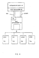
- the notebook PC 10 includes CPU 12, host bus 14, chip set (440DX) 16, memory 18, PCI bus 20, IDE controller 22, bay controller 24, IDE interface 26, internal HDD 28, source circuit 30, amplifier 32, speaker 34, and music interface 36.
- the CPU 12 controls an operation of all hardware and software, and may communicate via the host bus 14 the chip set 16 and memory 18, such as a RAM. Necessary programs are downloaded to the memory 18 from the HDD 28.
- the CPU 12 is connected to the IDE controller 22, bay controller 24 and source circuit 30 via the PCI bus 20.
- the IDE controller 22 transmits an instruction in accordance with the software stored in the HDD 28 to the bay attachment 50 under control by the CPU 12.
- the bay controller 24 transmits a power-on signal to the bay attachment 50 and expanding unit 70 connected to it.
- the port replicator 80 includes, as shown in FIG. 6, a pair of screws 81a and 81b, USB port 82, keyboard or mouse connector 83, multi-bay adapter 84, floppy disc connector 85, CRT connector 86, parallel interface 87, and serial interface 88.
- FIG. 6 is a rear view of the port replicator.
- the port replicater 80 includes connector 89 to notebook PC 10.
- FIG. 7 is an upper view of the port replicator 80.
- the screws 81a and 81b are used to attach the port replicator 80 to the notebook PC 10.
- the USB port 82 is used for a USB connection to another electronic hardware.
- a keyboard or mouse may be connected to the keyboard or mouse connector 83.
- a printer etc. may be connected to the parallel interface 87.
- a modem etc. may be connected to the serial interface 88.
- the port replicator 80 advantageously includes the multi-bay 84 and the floppy disc connector 85.
- the multi-bay adapter 84 is formed, for example, as a male 64 pin connector, and connectable to the cable 48 having a female 64 pin connector 481.
- the floppy disc connector 85 in the port replicator 80 is formed, for example, as male 26 pins, and connected to a connector (not shown) accommodated in the floppy disc storage part 55 via a cable (not shown) when the expanding unit 70 is a FDD as described later.
- the storage part 55 has a floppy disc connector inside a lid in FIG. 5. This connector is connected to the floppy disc connector 85 of the port replicator 80 in FIG. 6 through a cable.
- the bay attachment 50 connects, when thus connected to a FDD as the expanding unit 70 (FIG. 1), the FDD to the notebook PC body 10 via the port replicator 80.
- the FDD is connected to the notebook PC body 10 via the port replicator 80 in the embodiment shown in FIGs. 1 and 6, while a connector accommodated in the floppy disc connector storage part 55 (FIG. 5) may be connected to the notebook PC body 10 via a cable without using port replicator 80.
- the connector corresponding to the floppy disc connector 85 in the port replicator 80 in FIG. 6 is connected to the cable accommodated in the floppy disc connector storage part 55 (FIG. 5) via the cable.
- the connector corresponding to the floppy disc connector 85 in the port replicator 80 in FIG. 6 may be located at any place in the notebook PC body 10. As an example, it is provided at the rear surface of the notebook PC body 10 (or a part to which the port replicator 80 is connected in FIG. 1).
- the floppy disc connector stored in the floppy disc connector storage part 55 may be used to simply expand the notebook PC 10 with an external FDD.
- the cable 48 has an IDE interface and an analog music interface, as described later.
- the cable 48 is connected detachably to the port replicator 80, but may be connected detachably to the bay attachment 50.
- a preparation of a plurality of cables 48 having different lengths would enhance the operability of the computer system 100.
- the cable 48 spaces the notebook PC 10 from the bay attachment 50, thereby facilitating the miniaturization of the notebook PC 10 in comparison with the notebook PC 10 having an internal bay attachment.
- the bay attachment 50 includes storage part 51, control part 52, LT-LCD 54, operation part 56, and connector 58.
- the storage part 51 may detachably store the expanding unit 70. As long as the bay attachment 50 is made connectable to the expanding unit 70, it is not necessary to store the expanding unit in the storage part 51.
- the storage part 51 is preferable in that it protects the expanding unit 70 from tilt, direct vibration and impact.
- the control part 52, LT-LCD 54 and operation part 56 are schematically shown in FIG. 2, the LT-LCD 54 and the operation part 56 are connected to and controlled by the control part 52.
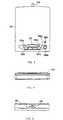
- the control part 56 includes, as shown in FIG. 3, rewind (return by one tune) button 56a, stop/eject button 56b, reproduction/pause button 56c, fast-forward (skip by one tune) button 56d, power source button 56e, unlock button 56f, and lamp 56g.
- FIG. 3 is an upper view of the bay attachment 50.
- the rewind button 56a returns music on a music CD by one tune, whereas the fast-forward button 56d skips music on a music CD by one tune.
- the stop/eject button 56b stops reproduction of a music CD, and ejects, when pressed twice, a medium in the expanding unit 70, such as a CD-ROM.
- the reproduction/pause button 56c plays and temporarily stops the reproduction of a music CD.
- the power source button 56e is used to power on and off the bay attachment 50 and the extension unit 70 when no application software is activated in the notebook PC 10.
- the bay controller 24 controls power on and off of them and the power source button 56e does not work substantially.
- operational information of the power source button 56e may be sent as a bay switch information signal to the bay controller 24 so as to reflect it on the application software.
- the unlock button 56f is used to electrically eject the expanding unit 70 from the bay attachment 50 during a process of the expanding unit 70 (such as a reproduction).
- the lamp 56g indicates red during a process of the expanding unit 70 and turns to green when the unlock button 56f is pressed.
- the unlock button 56f is convenient, for example, when the expanding unit 70 is replaced from a CD-ROM drive to DVD-ROM drive without turning off the power source.
- means for electrically ejecting the expanding unit 70 such as unlock button 56f
- means for mechanically ejecting the expanding unit 70 from the bay attachment 50 may be provided as floppy disc ejecting means provided in a general-purpose FDD.
- the bay attachment 50 has a front door 53 that is urged in a closing direction by a spring etc. at a front surface thereof.
- the expanding unit 70 is inserted into the storage part 51 against the spring force through the front door 53.
- the bay attachment 50 may open at a portion corresponding to the front door 53 without providing the front door 53.
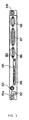
- the bay attachment 50 has a floppy disc connector storage part 55 at the rear surface in addition to the cable 48, and a floppy disc connector is provided inside the lid in FIG. 5 of the storage part 55.
- FIG. 4 is a front view of the bay attachment
- FIG. 5 is a rear view of the bay attachment.
- the bay attachment 50 and expanding unit 70 receive power from the notebook PC 10, and are made operable by the power on signal from the bay controller 24.
- the bay attachment 50 and expanding unit 70 may include a unique AC adapter and battery.
- the bay attachment 50 serves as a charger to the battery pack.
- the bay attachment 50 has a bay structure, and is connectable compatibly to many types of expanding units 70 as described later.
- the bay attachment 50 is connectable to the notebook PC 10 via one cable 48 (or port replicator 80), and has connector 58 in the storage part 51 in the housing that is commonly used for different connectors when a FDD and a CD-ROM drive having these different connectors are used as an expanding unit 70.
- the bay attachment 50 in this embodiment is connected to the notebook PC via the port replicator 80, but may be connected to the notebook PC without the port replicator 80.
- a member corresponding to the multi-bay adapter 84 shown in FIG. 6 is provided in the notebook PC body 10 and connected to the connector 481 in the bay attachment 50.
- a member corresponding to the multi-bay adapter 84 may be located at any place in the notebook PC 10 body.
- the member corresponding to the multi-bay adapter 84 may be provided in the back of the notebook PC 10 body (or a portion to which the port replicator 80 is connected in FIG. 1).
- the expanding unit 70 is selected from a group including, for example, a FDD, a CD-ROM drive, a magneto-optical (MO) disc drive, an LS-120 drive, a digital video disc (DVD-ROM) drive, a HDD, and an AC/DC adapter. Therefore, many devices are applicable to the expanding unit 70 and make the notebook PC 10 multifunctional.
- FIG. 2 omits the port replicater 80 and cable 48 for illustration purposes.
- FIG. 2 may be understood as an explanatory view of the bay attachment 50 connected to the notebook PC without port replicater 80.
- an operating system such as Windows 98® that has been stored in the internal HDD 28 is initiated.
- application software that is operable on such an OS is run.
- the bay controller 24 sends power on signal P ON to the bay attachment 50 so as to power it on.
- the IDE controller 22 instructs, under control by the CPU 12, the control part 52 of the bay attachment 50 to reproduce the music CD via the IDE interface 26.
- the control part 52 instructs the music CD reproducer 70 to reproduce the music CD.
- the reproduced audio signal is supplied to the amplifier 32 via the music analog interface 36.
- the amplifier 32 receives the power on signal P ON from the source circuit 30, not from the bay attachment 50.
- Information on the reproduction time and the order of tunes etc. on the music CD may be indicated on the LT-LCD 54, but usually indicated only on the display of the notebook PC 10.
- the amplifier 32 transmits the amplified signal to the speaker 34 by amplifying the audio signal. Thereby, the music CD is reproduced from the speaker 34.
- the bay attachment 50 supplies to the bay controller 24 bay switch information signal BS that informs that the operation part 56 is pressed in the bay attachment 50.
- the bay switch information signal BS serves to reflect the operation of the operation part 56 on the application software. In other words, it has a similar effect to mouse click selecting a reproduction of the music CD. No reproduction instruction is sent from the IDE controller 32 in this case.
- the reproduced audio signal is supplied to the amplifier 32 via the music analog interface 36.
- the amplifier 32 receives the power on signal P ON from the source circuit 30, not from the bay attachment 50.
- Information on the reproduction time and the order of tracks on the music CD may be indicated on the LT-LCD 54, but usually indicated only on the display of the notebook PC 10.
- the amplifier 32 transmits the amplified signal to the speaker 34 by amplifying the audio signal. Thereby, the music CD is reproduced from the speaker 34.
- the control part 52 in the bay attachment 50 operates independent of the CPU 12, IDE controller 22 and bay controller 24 in the notebook PC 10.
- the controller 52 transmits the power on signal P ON to the amplifier 32 so as to make it operable and transmits the audio signal to the amplifier 32.
- Information on the track length and the order of tracks etc. on the music CD may be indicated on the LT-LCD 54.
- the display on the notebook PC 10 is not powered and thus indicates no information.
- the amplifier 32 transmits the amplified signal to the speaker 34 by amplifying the audio signal. Thereby, the music CD is reproduced from the speaker 34.
- the bay attachment 50 uses as a connection part the cable 48 and the connector 481 to be connected to the notebook PC 10 (with or without port replicator 80) in this embodiment, the connection part of this embodiment may cover the direct and indirect connection with the electronic hardware. As described in the embodiment, the bay attachment 50 may be connected to the notebook PC 10 directly or via the port replicator 80. In either structure, the cable 48 and the connector 481 of the present invention each constitute a connection part.
- the bay attachment 50 may be connected to the notebook PC as an integrated body. This connection mode is the same as that where a so-called docking station is connected to a portable computer. As explained with reference to FIG. 9, the bay housing 270 may be connected to the portable computer 40. This type of connection would require the operation part to be equipped with an aspect of the bay housing 270, for example.
- the bay attachment 50 may be connected to the notebook PC 10 by a radio format, such as infrared or electromagnetic wave.
- the infrared transmitter/receiver module bay attachment 50 may be connected to the notebook PC 10.
- an infrared transmitter/receiver module (which includes an infrared LED, a photodiode, and a modulator/demodulator) may be provided in both the bay attachment 50 and the notebook PC 10 so as to secure data communications.
- the transmitter/receiver may be made by a photodiode and an infrared LED.
- This type of connection may use, but is not limited to, the infrared data communication standard prescribed by the well-known IrDA (Infrared Data Association).
- the radio communication is not limited to the above infrared, but may use other electromagnetic waves.
- the communication does not require a bi-directional communication between the bay attachment 50 and the notebook PC body 10, and may use a uni-directional communication from the bay attachment 50 to the notebook PC body 10.
- the radio connection constitutes one type of connection in the present invention.
- the bay attachment 50 includes two connection parts.
- FIG. 8 a description will now be given of an embodiment about the notebook PC body 10 whose supplemental function is expanded by providing the CD-ROM drive 702, LS-120 drive 703, or DVD-ROM 704 in the bay attachment 50 (FIGs. 3 and 8).
- the cable 48 and the connector 481 each are a connection part which connects the notebook PC body 10 to the bay attachment 50, and include interfaces for the CD-ROM drive 702, LS-120 drive 703, and DVD-ROM drive 704.
- One of the CD-ROM drive 702, LS-120 drive 703, and DVD-ROM drive 704 is connected to the bay attachment 50, as described with reference to FIGs. 1 through 7.
- the floppy disc drive 701 is connected, as described with reference to FIG. 5, to the notebook PC body 10 via a cable (551 in FIG. 8) and a cable (not shown) stored in the floppy disc connector storage part 55.
- the storage part 55 stores a connector for a floppy disc inside the lid in FIG. 5. This connector is connected to the floppy disc connector in the port replicator 80 in FIG. 6 via a cable.
- the FDD is connected as an expanding unit 70 (FIG. 1) to the bay attachment 50
- the floppy disc drive (701 in FIG. 8) is connected to the notebook PC body 10 via the cable 551 (FIG. 8) and the port replicator 80.
- the connector stored in the floppy disc connector storage part 55 may use the cable 551 (FIG. 8) for connection with the notebook PC body 10 without the port replicator 80.
- This structure may require the notebook PC body 10 to include a connector corresponding to the floppy disc connector 85 in the port replicator 80 so as to be connectable to the connector stored in the floppy disc connector storage part 55 (FIG. 5) via the cable 551.
- the connector corresponding to the floppy disc connector 85 in the port replicator 80 may be located at any place in the notebook PC 10. As an example, it may be provided at the rear of the notebook PC body 10 (or a portion to which the port replicator 80 is connected).
- the connector stored in the floppy disc connector storage part 55 may be used to simply expand the notebook PC 10 with an external FDD.
- the FDD 701 is connected by the connector 55 and cable 551 which have different interfaces from the cable 48 and connector 481 as an interface for the CD-ROM drive 702, LS-120 drive 703 and DVD-ROM drive 704 (although the connector at the side of the port replicator is omitted).
- connection part such as a cable and connector
- the cable 48 and connector 481 (FIGs. 3 and 8) should be changed in specification or design. Accordingly, as shown in FIGs. 5 and 8, this embodiment provides, as an interface for the newly introduced object, i.e., FDD, another cable 551, connector (stored in the floppy disc connector storage part 55 in FIG. 5), the connector (not shown) of the cable 551 connectable to the foregoing connector, and the connector (not shown) of the cable for connection with the port replicator 80, eliminating the necessary design change of the cable 48 and connector 481.
- the present invention eliminates a great design change of the bay attachment and merely adds an interface cable or connector for a newly introduced unit when the newly introduced unit is attempted to the bay attachment 50 for the computer at the subsequent stage.
- the computer at the subsequent stage is expanded with the newly introduced unit only when the newly introduced unit is connected to the bay attachment 50, without changing the bay attachment 50 and the cable for each additional unit.
- the reduction of the number of development steps for the entire apparatus and the appropriation of the conventional equipment would contribute to the reduction of the development cost.
- FIGs. 1, 3 and 8 refer to the cable connecting the bay attachment 50 to the notebook PC 10
- a design change of the cable 48 for the newly introduced expanding unit would increase the number of signal lines and thicken the cable.
- the cable becomes thick the flexibility of the cable becomes lowered.
- the low flexibility would restrict the arrangement of the bay attachment, for example, on a desk, and thus the cable should be relatively long to make it flexible.
- the present invention employs another cable as another connection part for use with an interface of the newly introduced expanding unit, and would not thicken the cable or deteriorate its flexibility. Therefore, no long cable 48 is needed.
- the cable 551 can be releasably attached to the bay attachment 50.
- FIGs. 3 and 5 illustrate that the connector that is connectable to the cable 551 is stored in the floppy disc connector storage part 55 (FIG. 5). This structure does not require two cables to be always connected to the bay attachment 50, facilitating an operation of the bay attachment 50.
- the FDD cable 551 is detachable for users who do not use the FDD, so as to enhance the portability and other features of the bay attachment 50.
- a structure that makes the cable 48 detachable may be adopted.
- One of the effects of the present invention may be achieved by fixing the cable 551 onto the bay attachment 50 as the cable 48 in FIG. 3.
- the present invention covers a structure that does not use the cable 48.
- the connection part of the present invention is not limited to the cables 48 and 551.
- the present invention covers, for example, a connection structure similar to that between the bay housing 270 and the portable PC 240 in FIG. 9.
- the connector 95 shown in FIG. 9 may be connected, when the cable 48 is not used, to the connector provided at the lower part in the portable PC 240.
- the present invention uses, when applied to the structure shown in FIG. 9, the previously provided connector 95 as an interface for the previously provided expanding units.
- Another new connector is provided as an interface for the newly introduced expanding unit in the bay housing 270 so as to connect the new expanding unit to the portable PC 40.
- Another connector part that is connectable to the new connector may be provided, as in the connector 95, at the bottom of the portable PC 40.
- the above embodiments refer to the FDD as the expansion unit for illustrative purposes, and any other device may be used as the expansion unit.
- the present invention has been thus discussed in a case where a new expansion FDD is introduced to a device using as an interface the cable 48 and connector 481 so as to expand a function of the notebook PC body 10 by providing the CD-ROM drive 702, LS-120 drive 703 and DVD-ROM drive 704 in the bay attachment 50 (FIGs. 3 and 8).
- a device using as an interface the cable 48 and connector 481 so as to expand a function of the notebook PC body 10 by providing the CD-ROM drive 702, LS-120 drive 703 and DVD-ROM drive 704 in the bay attachment 50 is merely assumed for explanation purposes of the present invention, and this assumption does not admit that such a unit was known or used at the time of filing of this application.
- a second embodiment of the invention comprises a function expanding device including a first connection part connectable to a unit that expands electronic hardware, a second connection part connectable to the electronic hardware, and a third connection part connectable to said electronic hardware.
- the second connection part for example, connects to the hardware the unit that has been conventionally connected to the function expanding device.
- the third connection part connects to the electronic hardware the unit that is newly designed to be connectable to the electronic hardware. An attempt to connect a newly introduced unit and a conventionally expandable unit to the electronic hardware by one connection part would necessarily alter a conventional connection part to the electronic hardware.
- the third connection part connects the newly introduced unit to the electronic hardware without changing the design of the connection part in the electronic hardware, whereas the second connection part serves as a connection part between the conventionally connectable unit and electronic hardware. It is therefore sufficient to design only the third connection part for the additional unit. The reduction of the number of development steps for the entire apparatus and the appropriation of the conventional equipment would reduce the development cost.
- the third connection part may connect the conventionally connectable unit to the electronic hardware while the second connection part may connect to the electronic hardware the newly introduced unit designed to be connected to it.
- the unit group is divided into the second and third connection parts, the number of units for each connection part becomes reduced in comparison with that where only one connection part handles all the units.
- the connection part is a connector or a cable, the number of signal lines reduces and becomes small.
- the function expanding device comprises an operation part for a unit that expands a function of electronic hardware, and thus enables the unit to be operated not only by the electronic hardware but also by the function expanding device. Therefore, the function expanding device itself becomes multifunctional.
- the function expanding device may reproduce a music CD as a unit medium using a function expanding unit without using a control part in the electronic hardware. Therefore, the function expanding device may save labor and power associated with an initiation of application software in electronic hardware, enhancing the operability.
- the operation part may power on at least part of the electronic hardware.
- the operation part may transmit the power-on signal to the amplifier. Therefore, even when the power-on signal is not supplied to the amplifier after the application in the electronic hardware is run, if power is supplied to the electronic hardware (by an AC adapter or a battery) the control part of the function expanding device may control the amplifier in the electronic hardware
- the control part may (instruct a related component to) transmit operational information of the operation part to the electronic hardware. Therefore, for example, the operational information of the operation part may reflect on and synchronize with application software in the electronic hardware. Thereby, a similar effect may be obtained by an operation of the operation part in the function expanding device in addition to an operation of the electronic hardware by a mouse click.
- the second connection may be connectable to the electronic hardware via a port replicator.
- the second connection part may have a cable which spaces the electronic hardware from the function expanding device. Therefore, this electronic hardware may be made light and smaller than the electronic hardware that has been directly connected to the function expanding device. In addition, an arrangement of the function expanding device and the electronic hardware in accordance with a shape of the installation space would enhance the operability.
- the function expanding device may further comprise a display part which displays a status of the unit, and a user of the function expanding device may confirm the operation.
- this function expanding device is suitable when only the control part of the function expanding device controls the unit without using the display part (for example, a LCD) in the electronic hardware.
- the unit may use a plurality of devices, such as a music CD drive, a CD-ROM drive, a DVD-ROM drive, and an LS-120 drive. Therefore, the electronic hardware need not conveniently have a connection part for each unit drive, and may become multifunctional and miniature.
- DVD-ROM and "LS-120” drives also embrace other types of drive of similar formats such as DVD-RAM, DVD-R, or DVD-Audio and any drive employing 31 ⁇ 2-inch removable magnetic media.
- the present invention can be applied to other types of drive, e.g. external hard disk drives, and to other types of media, e.g. solid-state memory cards, as well.
- the second connector may use IDE and music interfaces, and thus the electronic hardware may become multifunctional.
- a port replicator may connect the above function expanding device to the electronic hardware. More concretely, this port replicator is novel in comparison with a conventional port replicator in having the third connection part connectable to the second connection part.
- a function expanding device may enable a design of the third connection part for an additional unit.
- the reduction of the number of development steps for the entire apparatus and the appropriation of the conventional equipment would reduce the development cost.
- the unit group is divided into the second and third connection parts, the number of units for each connection part becomes reduced in comparison with that where only one connection part handles all the units.
- the connection part is a connector or a cable, the number of signal lines reduces and becomes small.
- the third connection part connects the newly introduced unit to the electronic hardware without changing the design of the connection part in the electronic hardware, whereas the second connection part serves as a connection part between the conventionally connectable unit and electronic hardware. It is therefore sufficient to design only the third connection part for the additional unit.
- the reduction of the number of development steps for the entire apparatus and the appropriation of the conventional equipment would reduce the development cost.
- the connection part is a connector or a cable, the number of signal lines reduces and each connection part becomes small. More specifically, a smaller connector or thinner cable may be provided.
Abstract
Description
- The present invention relates to attachments that are connectable to electronic hardware, such as a notebook personal computer ("PC") to expand their functions.
- The recent development and spread of notebook PCs have been increasingly demanding a notebook PC that is light for portability purposes and multifunctional on a desk. The PC body itself is thus made light, whereas various expansion or extension units, such as a CD-ROM drive and a floppy disc drive, connectable to or built in have been proposed.
- However, the conventional expanding units, such as a CD-ROM drive, if built in the computer body would bulk up the body and deteriorate its portability. Those drives which are different in specification, such as a CD-ROM drive and a high density floppy disc (LS-120), use different connectors for connection with the PC body. An attempt to expand a notebook PC with multiple functions (or specifications) would thus need a plurality of connectors accordingly, which prevents a realization of a miniature PC body. In other words, a conventional notebook PC cannot include multiple connectors in order to realize the miniaturization, and thus it cannot become multifunctional. Moreover, as a CPU in the PC body controls a CD-ROM drive (or a music compact disc ("CD") drive), listening to a music CD arduously needs run application software that is installed in the PC body. This operation is time-consuming and not easy.
- Accordingly, the assignee filed Japanese Patent Application No. 10-260602 entitled "function expanding device, component unit, and electronic hardware" on September 14, 1998. FIG. 9 shows notebook PC
related attachment group 250 and notebook PC 240. - The notebook PC
related attachment group 250 includesbay housing 270, floppy disc drive ("FDD") 110, CD-ROM drive 130, magneto-optical ("MO")disc drive 140, highdensity floppy disc 150, digital video disk ("DVD")drive 160, hard disc drive ("HDD") 170, AC/DC adapter 180, andbattery pack 190. The FDD 110, CD-ROM drive 130,MO disc drive 140, high densityfloppy disc drive 150,DVD drive 160, andHDD 170 each constitute an expanding unit (expansion unit). -
Function expanding unit 260 for a notebook PC is made by attaching thebattery pack 190 to thebay housing 270 and inserting one of the FDD 110, CD-ROM drive 130,MO disc drive 140, high densityfloppy disc drive 150,DVD drive 160, HDD 170 and AC/DC adapter 180. There are eight modes and its capability of extension is wider than the conventional notebook PC.Unit 260 is attached to the bottom of the notebook PC 240 and serves as a charger for thebattery pack 190, and as a rack for the notebook PC 240. When the notebook-PCfunction expanding unit 260 is attached to the notebook PC 240, the notebook PC 240 and the notebook-PCfunction expanding unit 260 are electrically connected to each other, expanding the function of the notebook PC 240. - The
bay housing 270 has bay 273 as a storage part. Thebay 273 is a flat space corresponding to an outer shape of the FDD 110, etc., and has an opening into which the FDD 110 or the like is inserted. - As shown in FIG. 9, the
above devices DC adapter 180 have approximately similar flat outer shapes that may be inserted into and correspond to thebay 273 in thebay housing 270, and includeconnectors - As shown in FIG. 9, the
floppy disc drive 110 has an outer shape that may be inserted into and corresponds to thebay 273, and includesconnector 111 at the top in the insertion direction. - The
connectors bay housing 270. The connector 295 in thebay housing 270 is connected to a connector (not shown) at the bottom of the notebook PC 240. In this way, thebay housing 270 enables various expanding units to be connected to the notebook PC 240 while making light the body of the notebook PC 240 and reducing the number of connectors in the notebook PC. - The
computer body 240 controls the FDD 110, CD-ROM drive 130,MO disc drive 140, high densityfloppy disc drive 150,DVD drive 160,HDD 170, etc. Control by the CPU in the PC body over the CD-ROM drive (or CD drive) etc., needs hard-to-use application software installed in the PC body even just to listen to a music CD. This operation is time-consuming and not easy. More specifically, where thecomputer body 240 operates the expanding unit, a user may feel that running of the PC and control over fast-forwarding and positioning at the head of a desired tune using PC's application software interface are harder than operations of the ordinary audio equipment. General CD performance software for PCs indicates on a PC display the way of operations for an operation part on a CD player and requires a user to input a desired performance button etc. on the indicated operational part by using a pointing device, such as a mouse. This CD performance means has a disadvantage in that a user must wait a period of time for PC and software activations. Track selection of a CD needs an interface using a mouse or other input means on the PC, and the way of operation becomes disadvantageously different between the PC and the ordinary audio equipment. This exemplifies a CD, but similar disadvantages are seen for DVD drives and other peripherals. - In an attempt to connect a new expanding unit (for example, a supplemental storage) to a computer body, the function expanding device (or the bay housing 270) should be altered accordingly.
- Before another expanding unit having a different specification is connected to a computer body, a specification of the function expanding device and a specification of a connection part (the connector 295 in FIG. 9) should be redesigned. In other words, the specification for the connector 295 in FIG. 9 is determined so as to correspond to the expanding
units computer body 240 and integrates them as one member, but it is conceivable to connect them using a cable. In this case, an addition of an expanding unit having a different specification thus requires a change of cable specification (such as the number of signal lines). These design and specification changes increase the number of development steps of the entire apparatus and thus the development cost. Although new peripherals for PCs are more and more developed, a connection of these peripherals to the notebook PC 240 via the function expanding device (or bay housing 270) would increase the design and specification changes. - It is a consideration of the present invention to provide a function expanding device in which the above disadvantages are eliminated.
- It is a further consideration of the present invention to provide a function expanding device that renders electronic hardware multifunctional, small, light, and easy to use.
- According to a first aspect of the present invention there is provided a function expanding device (expansion device) comprising a first connection part connectable to a unit which expands a function of electronic hardware, a second connection part connectable to the electronic hardware, and an operation part for the unit. This function expanding device enables the unit to be operated not only by the electronic hardware but also by an operational part in the function expanding device.
- The function expanding device may further comprise a control part which may control the unit independent of the electronic hardware. For example, when the electronic hardware has a speaker and the unit is a CD-ROM drive that may reproduce both a music CD and a CD-ROM, the control part of the function expanding device may control the reproduction of the music CD independent of the electronic hardware.
- The operation part may power on at least part of the electronic hardware. For example, when the electronic hardware has an amplifier that amplifies an audio signal in a music CD, the operation part may transmit the power-on signal to the amplifier Thus, for example, even when the power-on signal is not supplied to the amplifier after the application in the electronic hardware runs, if power is supplied to the electronic hardware (by an AC adapter or a battery) the control part of the function expanding device may control the amplifier in the electronic hardware.
- The control part may transmit operational information of the operation part to the electronic hardware. Thus, for example, the operational information of the operation part may reflect on and synchronize with application software in the electronic hardware.
- Preferably, the second connection part is connectable to a port replicator,and connectable to the electronic hardware via the port replicator. The second connection part may thus be connected indirectly to the electronic hardware.
- The second connection part may have a cable. Therefore, this electronic hardware may be made smaller than the electronic hardware that has an internal connector.
- The function expanding device may further comprise a display part which displays a status of the unit and enables a user of the function expanding device to confirm the operation. In particular, this function expanding device is suitable when only the control part of the function expanding device controls the unit without using the display part (for example, a LCD) in the electronic hardware.
- Preferably, the unit is a music CD drive, a CD-ROM drive, a DVD-ROM drive, or an LS-120 drive, and the first connection part has a bay structure connectable compatibly to either drive in the group. Therefore, the electronic hardware need not conveniently have a connection part for each unit drive and may become multifunctional and miniature.
- The second connector my have an IDE and music interfaces. Therefore, the electronic hardware may correspond to a unit pursuant to these interfaces and become multifunctional.
- According to a second aspect of the present invention, there is provided a port replicator connectable to a function expanding device which includes a first connection part connectable to a unit which expands a function of electronic hardware, a second connection part connectable to the electronic hardware, and an operation part of the unit, comprises a third connection part connectable to the second connection part of the function expanding device, and a fourth connection part connectable to the electronic hardware. This port replicator is novel in comparison with a conventional port replicater in having the third connection part connectable to the second connection part of the function expanding device.
- According to a third aspect of the present invention, there is provided a function expanding device comprising a first connection part connectable selectively to a plurality of units each of which expands a function of electronic hardware, a second connection part connectable to the electronic hardware, and a third connection part connectable to the electronic hardware. This function expanding device is novel in having two connection parts.
- For example, the second connection part in this function expanding device may connect to the electronic hardware a unit which has been able to be connected to the function expanding device. On the other hand, the third connection part may connect to the electronic hardware the unit designed to be newly connected to it.
- An attempt to connect a newly introduced unit and a conventionally expandable unit to the electronic hardware by one connection part would necessarily alter a conventional connection part for connection with the electronic hardware. In contrast, according to the above structure, the third connection part connects the newly introduced unit to the electronic hardware without changing the design of the connection part in the electronic hardware, whereas the second connection part serves as a connection part between the conventionally connectable unit and electronic hardware. It is therefore sufficient to design only the third connection part for the additional unit. The reduction of the number of development steps for the entire apparatus and the appropriation of the conventional equipment would reduce the development cost. Instead, the third connection part may connect the conventionally connectable unit to the electronic hardware while the second connection part may connect to the electronic hardware the newly introduced unit designed to be connected to it. When the unit group is divided into the second and third connection parts, the number of units for each connection part becomes reduced in comparison with that where only one connection part handles all the units. When the connection part is a connector or a cable, the number of signal lines reduces and becomes small.
- In the function expanding device, these second and third connection parts may be used to connect to the electronic hardware those units connectable to the first connection part, but different to each other. The second connection part may be used to connect to the electronic hardware at least one of said plurality of units connectable to the first connection part, and the third connection part may be used to connect to the electronic hardware at least one of the units connectable to the first connection part, which unit is different from the unit connected by the second connection part.
- For example, the second connection part connects to the electronic hardware the unit that has been connectable to the function expanding device in the conventional structure, while the third connection part connect to the electronic hardware the unit designed to be newly connected to it.
- An attempt to connect a newly introduced unit and a conventionally expandable unit to the electronic hardware by one connection part would necessarily alter a conventional connection part to the electronic hardware. In contrast, according to the above embodiment, the third connection part connects the newly introduced unit to the electronic hardware without changing the design of the connection part in the electronic hardware, whereas the second connection part serves as a connection part between the conventionally connectable unit and electronic hardware. It is therefore sufficient to design only the third connection part for the additional unit. The reduction of the number of development steps for the entire apparatus and the appropriation of the conventional equipment would reduce the development cost.
- Instead, the third connection part may connect the conventionally connectable unit to the electronic hardware while the second connection part may connect to the electronic hardware the newly introduced unit designed to be connected to it. The second and third connection parts handle different units, and the number of units for each connection part becomes reduced in comparison with that where only one connection part handles all the units. When the connection part is a connector or a cable, the number of signal lines reduces and becomes small.
- According to a fourth aspect of the present invention there is provided a function expanding device comprising a first connection part connectable to a unit that expands electronic hardware; a second connection part connectable to the electronic hardware; and a third connection part connectable to the electronic hardware.
- A detailed description will now be given, by way of example, with reference to the accompany drawings, in which:
- FIG. 1 is a schematic perspective view of an embodiment of the present invention.
- FIG. 2 is an exemplified block diagram of the embodiment shown in FIG. 1.
- FIG. 3 is an upper view of a bay attachment shown in FIG. 1.
- FIG. 4 is a front view of the bay attachment shown in FIG. 1.
- FIG. 5 is a rear view of the bay attachment shown in FIG. 1.
- FIG. 6 is a rear view of the port replicator shown in FIG. 1.
- FIG. 7 is an upper view of the port replicater shown in FIG. 1.
- FIG. 8 is another exemplified block diagram of the embodiment shown in FIG. 1.
- FIG. 9 is a function expanding device disclosed in a prior patent application filed by this applicant.
-
- FIG. 1 is a schematic perspective view of a
computer system 100, and FIG. 2 is a block diagram thereof. As shown in FIG. 1, thecomputer system 100 embodying the invention includesnotebook PC 10,cable 48, function expanding device (bay attachment) 50, expandingunit 70, andport replicator 80. - The present invention is not limited to notebook PCs, but applicable to so-called laptop PCs, portable PCs, and mobile PCs.
- Referring to FIG. 1, the
notebook PC 10 may employ any structure known in the art, and have a mouse, trackball, joystick, etc. Thenotebook PC 10 is connected to the external power source via an AC adapter or a detachable lithium battery. Thenotebook PC 10 is a typical example of electronic hardware, but the electronic hardware to which the present invention is applicable is not limited to this type. - Although this embodiment describes using a data processor, such as notebook PCs, laptop PCs, portable PCs, and mobile PCs, the present invention is applicable, in addition to such computers, to personal digital assistants ("PDAs"), electronic notebooks, etc. Moreover, the present invention and embodiment are not limited to data processors, or other electronic hardware. For example, the
bay attachment 50 may be directly connected to a speaker and a headphone in order to reproduce a music CD. - Referring to FIG. 2, the
notebook PC 10 includesCPU 12,host bus 14, chip set (440DX) 16,memory 18,PCI bus 20,IDE controller 22,bay controller 24,IDE interface 26,internal HDD 28,source circuit 30,amplifier 32,speaker 34, andmusic interface 36. TheCPU 12 controls an operation of all hardware and software, and may communicate via thehost bus 14 the chip set 16 andmemory 18, such as a RAM. Necessary programs are downloaded to thememory 18 from theHDD 28. TheCPU 12 is connected to theIDE controller 22,bay controller 24 andsource circuit 30 via thePCI bus 20. TheIDE controller 22 transmits an instruction in accordance with the software stored in theHDD 28 to thebay attachment 50 under control by theCPU 12. Thebay controller 24 transmits a power-on signal to thebay attachment 50 and expandingunit 70 connected to it. - The
port replicator 80 includes, as shown in FIG. 6, a pair ofscrews USB port 82, keyboard ormouse connector 83,multi-bay adapter 84,floppy disc connector 85,CRT connector 86,parallel interface 87, andserial interface 88. Hereupon, FIG. 6 is a rear view of the port replicator. As shown in FIG. 7, theport replicater 80 includesconnector 89 tonotebook PC 10. FIG. 7 is an upper view of theport replicator 80. - The
screws port replicator 80 to thenotebook PC 10. TheUSB port 82 is used for a USB connection to another electronic hardware. A keyboard or mouse may be connected to the keyboard ormouse connector 83. A printer etc. may be connected to theparallel interface 87. A modem etc. may be connected to theserial interface 88. - The
port replicator 80 advantageously includes the multi-bay 84 and thefloppy disc connector 85. Themulti-bay adapter 84 is formed, for example, as a male 64 pin connector, and connectable to thecable 48 having a female 64 pin connector 481. Thefloppy disc connector 85 in theport replicator 80 is formed, for example, as male 26 pins, and connected to a connector (not shown) accommodated in the floppydisc storage part 55 via a cable (not shown) when the expandingunit 70 is a FDD as described later. Thestorage part 55 has a floppy disc connector inside a lid in FIG. 5. This connector is connected to thefloppy disc connector 85 of theport replicator 80 in FIG. 6 through a cable. Thebay attachment 50 connects, when thus connected to a FDD as the expanding unit 70 (FIG. 1), the FDD to thenotebook PC body 10 via theport replicator 80. - The FDD is connected to the
notebook PC body 10 via theport replicator 80 in the embodiment shown in FIGs. 1 and 6, while a connector accommodated in the floppy disc connector storage part 55 (FIG. 5) may be connected to thenotebook PC body 10 via a cable without usingport replicator 80. According to this structure, the connector corresponding to thefloppy disc connector 85 in theport replicator 80 in FIG. 6 is connected to the cable accommodated in the floppy disc connector storage part 55 (FIG. 5) via the cable. The connector corresponding to thefloppy disc connector 85 in theport replicator 80 in FIG. 6 may be located at any place in thenotebook PC body 10. As an example, it is provided at the rear surface of the notebook PC body 10 (or a part to which theport replicator 80 is connected in FIG. 1). - The floppy disc connector stored in the floppy disc
connector storage part 55 may be used to simply expand thenotebook PC 10 with an external FDD. - The
cable 48 has an IDE interface and an analog music interface, as described later. Thecable 48 is connected detachably to theport replicator 80, but may be connected detachably to thebay attachment 50. For example, a preparation of a plurality ofcables 48 having different lengths would enhance the operability of thecomputer system 100. Thecable 48 spaces thenotebook PC 10 from thebay attachment 50, thereby facilitating the miniaturization of thenotebook PC 10 in comparison with thenotebook PC 10 having an internal bay attachment. - Referring to FIG. 2, the
bay attachment 50 includesstorage part 51,control part 52, LT-LCD 54,operation part 56, and connector 58. Thestorage part 51 may detachably store the expandingunit 70. As long as thebay attachment 50 is made connectable to the expandingunit 70, it is not necessary to store the expanding unit in thestorage part 51. Thestorage part 51 is preferable in that it protects the expandingunit 70 from tilt, direct vibration and impact. Although thecontrol part 52, LT-LCD 54 andoperation part 56 are schematically shown in FIG. 2, the LT-LCD 54 and theoperation part 56 are connected to and controlled by thecontrol part 52. - The
control part 56 includes, as shown in FIG. 3, rewind (return by one tune)button 56a, stop/eject button 56b, reproduction/pause button 56c, fast-forward (skip by one tune)button 56d,power source button 56e, unlock button 56f, and lamp 56g. FIG. 3 is an upper view of thebay attachment 50. Therewind button 56a returns music on a music CD by one tune, whereas the fast-forward button 56d skips music on a music CD by one tune. The stop/eject button 56b stops reproduction of a music CD, and ejects, when pressed twice, a medium in the expandingunit 70, such as a CD-ROM. The reproduction/pause button 56c plays and temporarily stops the reproduction of a music CD. - The
power source button 56e is used to power on and off thebay attachment 50 and theextension unit 70 when no application software is activated in thenotebook PC 10. When application software runs in thenotebook PC 10, thebay controller 24 controls power on and off of them and thepower source button 56e does not work substantially. Optionally, even in this case, operational information of thepower source button 56e may be sent as a bay switch information signal to thebay controller 24 so as to reflect it on the application software. The unlock button 56f is used to electrically eject the expandingunit 70 from thebay attachment 50 during a process of the expanding unit 70 (such as a reproduction). The lamp 56g indicates red during a process of the expandingunit 70 and turns to green when the unlock button 56f is pressed. The unlock button 56f is convenient, for example, when the expandingunit 70 is replaced from a CD-ROM drive to DVD-ROM drive without turning off the power source. Instead of means for electrically ejecting the expandingunit 70, such as unlock button 56f, means for mechanically ejecting the expandingunit 70 from thebay attachment 50 may be provided as floppy disc ejecting means provided in a general-purpose FDD. - As shown in FIG.4, the
bay attachment 50 has afront door 53 that is urged in a closing direction by a spring etc. at a front surface thereof. The expandingunit 70 is inserted into thestorage part 51 against the spring force through thefront door 53. Optionally, thebay attachment 50 may open at a portion corresponding to thefront door 53 without providing thefront door 53. As shown in FIG. 5, thebay attachment 50 has a floppy discconnector storage part 55 at the rear surface in addition to thecable 48, and a floppy disc connector is provided inside the lid in FIG. 5 of thestorage part 55. FIG. 4 is a front view of the bay attachment, while FIG. 5 is a rear view of the bay attachment. - The
bay attachment 50 and expandingunit 70 receive power from thenotebook PC 10, and are made operable by the power on signal from thebay controller 24. Optionally, thebay attachment 50 and expandingunit 70 may include a unique AC adapter and battery. Thebay attachment 50 serves as a charger to the battery pack. Thebay attachment 50 has a bay structure, and is connectable compatibly to many types of expandingunits 70 as described later. Thebay attachment 50 is connectable to thenotebook PC 10 via one cable 48 (or port replicator 80), and has connector 58 in thestorage part 51 in the housing that is commonly used for different connectors when a FDD and a CD-ROM drive having these different connectors are used as an expandingunit 70. - The
bay attachment 50 in this embodiment is connected to the notebook PC via theport replicator 80, but may be connected to the notebook PC without theport replicator 80. In this case, a member corresponding to themulti-bay adapter 84 shown in FIG. 6 is provided in thenotebook PC body 10 and connected to the connector 481 in thebay attachment 50. A member corresponding to themulti-bay adapter 84 may be located at any place in thenotebook PC 10 body. As an example, the member corresponding to themulti-bay adapter 84 may be provided in the back of thenotebook PC 10 body (or a portion to which theport replicator 80 is connected in FIG. 1). - The expanding
unit 70 is selected from a group including, for example, a FDD, a CD-ROM drive, a magneto-optical (MO) disc drive, an LS-120 drive, a digital video disc (DVD-ROM) drive, a HDD, and an AC/DC adapter. Therefore, many devices are applicable to the expandingunit 70 and make thenotebook PC 10 multifunctional. Thecontrol part 52 may identify which device is inserted into the expandingunit 70. Any identification method may be used. For example, 23=8 identification patterns would be obtained by independently flowing high and low signals through three signal lines. Therefore, eight types of devices as the expandingunits 70 may be identified by using such a signal combination. - With reference to FIG. 2, a description will now be given of reproduction of a music CD inserted into expanding
unit 70 as a music CD reproducer. FIG. 2 omits theport replicater 80 andcable 48 for illustration purposes. Alternatively, FIG. 2 may be understood as an explanatory view of thebay attachment 50 connected to the notebook PC withoutport replicater 80. - A description will now be given of a reproduction of a music CD by application software installed in the
notebook PC 10. In this case, an operating system (OS) such as Windows 98® that has been stored in theinternal HDD 28 is initiated. Then, application software that is operable on such an OS is run. For example, when a music CD is selected by clicking a mouse not shown in FIG. 1 on the application software, thebay controller 24 sends power on signal PON to thebay attachment 50 so as to power it on. TheIDE controller 22 instructs, under control by theCPU 12, thecontrol part 52 of thebay attachment 50 to reproduce the music CD via theIDE interface 26. - In response, the
control part 52 instructs themusic CD reproducer 70 to reproduce the music CD. The reproduced audio signal is supplied to theamplifier 32 via themusic analog interface 36. Hereupon, theamplifier 32 receives the power on signal PON from thesource circuit 30, not from thebay attachment 50. Information on the reproduction time and the order of tunes etc. on the music CD may be indicated on the LT-LCD 54, but usually indicated only on the display of thenotebook PC 10. Theamplifier 32 transmits the amplified signal to thespeaker 34 by amplifying the audio signal. Thereby, the music CD is reproduced from thespeaker 34. - A description will now be given of a reproduction of a music CD through an operation of the
operation part 56 in thebay attachment 50 where the OS in thenotebook PC 10 is initiated. In this case, thebay attachment 50 supplies to thebay controller 24 bay switch information signal BS that informs that theoperation part 56 is pressed in thebay attachment 50. The bay switch information signal BS serves to reflect the operation of theoperation part 56 on the application software. In other words, it has a similar effect to mouse click selecting a reproduction of the music CD. No reproduction instruction is sent from theIDE controller 32 in this case. - Then, the reproduced audio signal is supplied to the
amplifier 32 via themusic analog interface 36. Here, theamplifier 32 receives the power on signal PON from thesource circuit 30, not from thebay attachment 50. Information on the reproduction time and the order of tracks on the music CD may be indicated on the LT-LCD 54, but usually indicated only on the display of thenotebook PC 10. Theamplifier 32 transmits the amplified signal to thespeaker 34 by amplifying the audio signal. Thereby, the music CD is reproduced from thespeaker 34. - A description will now be given of a reproduction of a music CD through an operation of the
operation part 56 in thebay attachment 50 where no power is on (i.e., OS does not run) and thenotebook PC 10 is powered on by an AC mains supply or battery. In this case, thebay controller 24 andsource circuit 30 does not become operable even when thebay attachment 50 supplies to thebay controller 24 the bay switch signal BS that informs that theoperation part 56 is pressed in thebay attachment 56. Therefore, the bay switch information signal BS neither substantially works, nor contributes to the reproduction of the music CD except for theamplifier 32 andspeaker 34. - In this case, characteristically, the
control part 52 in thebay attachment 50 operates independent of theCPU 12,IDE controller 22 andbay controller 24 in thenotebook PC 10. Thecontroller 52 transmits the power on signal PON to theamplifier 32 so as to make it operable and transmits the audio signal to theamplifier 32. Information on the track length and the order of tracks etc. on the music CD may be indicated on the LT-LCD 54. The display on thenotebook PC 10 is not powered and thus indicates no information. Theamplifier 32 transmits the amplified signal to thespeaker 34 by amplifying the audio signal. Thereby, the music CD is reproduced from thespeaker 34. - Although the above description exemplifies a CD-ROM drive, the present invention is applicable to a DVD-ROM drive and other expanded devices.
- Although the
bay attachment 50 uses as a connection part thecable 48 and the connector 481 to be connected to the notebook PC 10 (with or without port replicator 80) in this embodiment, the connection part of this embodiment may cover the direct and indirect connection with the electronic hardware. As described in the embodiment, thebay attachment 50 may be connected to thenotebook PC 10 directly or via theport replicator 80. In either structure, thecable 48 and the connector 481 of the present invention each constitute a connection part. - In addition, although this embodiment uses the
cable 48 and connector 481, the present invention is not limited to these examples. Without thecable 48, thebay attachment 50 may be connected to the notebook PC as an integrated body. This connection mode is the same as that where a so-called docking station is connected to a portable computer. As explained with reference to FIG. 9, thebay housing 270 may be connected to the portable computer 40. This type of connection would require the operation part to be equipped with an aspect of thebay housing 270, for example. - Although the above examples connect the
bay attachment 50 to thenotebook PC 10 by thecable 48, connector 481, male 64 pins, female 64 pins etc., thebay attachment 50 may be connected to thenotebook PC 10 by a radio format, such as infrared or electromagnetic wave. As an example, the infrared transmitter/receivermodule bay attachment 50 may be connected to thenotebook PC 10. As an example, an infrared transmitter/receiver module (which includes an infrared LED, a photodiode, and a modulator/demodulator) may be provided in both thebay attachment 50 and thenotebook PC 10 so as to secure data communications. The transmitter/receiver may be made by a photodiode and an infrared LED. This type of connection may use, but is not limited to, the infrared data communication standard prescribed by the well-known IrDA (Infrared Data Association). The radio communication is not limited to the above infrared, but may use other electromagnetic waves. The communication does not require a bi-directional communication between thebay attachment 50 and thenotebook PC body 10, and may use a uni-directional communication from thebay attachment 50 to thenotebook PC body 10. As described, the radio connection constitutes one type of connection in the present invention. - As described above with reference to FIG. 3, the
bay attachment 50 includes two connection parts. With reference to FIG. 8, a description will now be given of an embodiment about thenotebook PC body 10 whose supplemental function is expanded by providing the CD-ROM drive 702, LS-120drive 703, or DVD-ROM 704 in the bay attachment 50 (FIGs. 3 and 8). Those elements in FIG. 8 which are designated by the same reference numerals in other figures denote the same elements. Thecable 48 and the connector 481 (FIGs. 3 and 8) each are a connection part which connects thenotebook PC body 10 to thebay attachment 50, and include interfaces for the CD-ROM drive 702, LS-120drive 703, and DVD-ROM drive 704. One of the CD-ROM drive 702, LS-120drive 703, and DVD-ROM drive 704 is connected to thebay attachment 50, as described with reference to FIGs. 1 through 7. - The
floppy disc drive 701 is connected, as described with reference to FIG. 5, to thenotebook PC body 10 via a cable (551 in FIG. 8) and a cable (not shown) stored in the floppy discconnector storage part 55. Thestorage part 55 stores a connector for a floppy disc inside the lid in FIG. 5. This connector is connected to the floppy disc connector in theport replicator 80 in FIG. 6 via a cable. When the FDD is connected as an expanding unit 70 (FIG. 1) to thebay attachment 50, the floppy disc drive (701 in FIG. 8) is connected to thenotebook PC body 10 via the cable 551 (FIG. 8) and theport replicator 80. - Although the
port replicator 80 connects the FDD to thenotebook PC body 10 in the embodiments shown in FIGs. 1, 6 and 8, the connector stored in the floppy disc connector storage part 55 (FIG. 5) may use the cable 551 (FIG. 8) for connection with thenotebook PC body 10 without theport replicator 80. This structure may require thenotebook PC body 10 to include a connector corresponding to thefloppy disc connector 85 in theport replicator 80 so as to be connectable to the connector stored in the floppy disc connector storage part 55 (FIG. 5) via thecable 551. The connector corresponding to thefloppy disc connector 85 in theport replicator 80 may be located at any place in thenotebook PC 10. As an example, it may be provided at the rear of the notebook PC body 10 (or a portion to which theport replicator 80 is connected). The connector stored in the floppy discconnector storage part 55 may be used to simply expand thenotebook PC 10 with an external FDD. - According to the structure shown in FIG. 8 (or FIGs. 3 and 5), the
FDD 701 is connected by theconnector 55 andcable 551 which have different interfaces from thecable 48 and connector 481 as an interface for the CD-ROM drive 702, LS-120drive 703 and DVD-ROM drive 704 (although the connector at the side of the port replicator is omitted). - For example, suppose there is a unit which uses the
cable 48 and connector 481 (FIG. 3) as an interface to enhance a function of thenotebook PC body 10 by providing the CD-ROM drive 702, LS-120drive 703 and DVD-ROM drive 704 in the bay attachment 50 (FIGs. 3 and 8), (although the existence of such a unit is assumed for explanation purposes of the invention and this assumption does not admit that such a unit was known or used at the time of filing of this application.) When a new FDD unit (701) is attempted to be expanded later, this embodiment does not use thecable 48 and connector 481 as an interface for the FDD unit (701). If only one connection part (such as a cable and connector) is used as an interface for a new device (such as theFDD unit 701 in this example), thecable 48 and connector 481 (FIGs. 3 and 8) should be changed in specification or design. Accordingly, as shown in FIGs. 5 and 8, this embodiment provides, as an interface for the newly introduced object, i.e., FDD, anothercable 551, connector (stored in the floppy discconnector storage part 55 in FIG. 5), the connector (not shown) of thecable 551 connectable to the foregoing connector, and the connector (not shown) of the cable for connection with theport replicator 80, eliminating the necessary design change of thecable 48 and connector 481. - As described, the present invention eliminates a great design change of the bay attachment and merely adds an interface cable or connector for a newly introduced unit when the newly introduced unit is attempted to the
bay attachment 50 for the computer at the subsequent stage. The computer at the subsequent stage is expanded with the newly introduced unit only when the newly introduced unit is connected to thebay attachment 50, without changing thebay attachment 50 and the cable for each additional unit. The reduction of the number of development steps for the entire apparatus and the appropriation of the conventional equipment would contribute to the reduction of the development cost. - Although FIGs. 1, 3 and 8 refer to the cable connecting the
bay attachment 50 to thenotebook PC 10, a design change of thecable 48 for the newly introduced expanding unit would increase the number of signal lines and thicken the cable. When the cable becomes thick, the flexibility of the cable becomes lowered. The low flexibility would restrict the arrangement of the bay attachment, for example, on a desk, and thus the cable should be relatively long to make it flexible. On the other hand, the present invention employs another cable as another connection part for use with an interface of the newly introduced expanding unit, and would not thicken the cable or deteriorate its flexibility. Therefore, nolong cable 48 is needed. - The
cable 551 can be releasably attached to thebay attachment 50. FIGs. 3 and 5 illustrate that the connector that is connectable to thecable 551 is stored in the floppy disc connector storage part 55 (FIG. 5). This structure does not require two cables to be always connected to thebay attachment 50, facilitating an operation of thebay attachment 50. TheFDD cable 551 is detachable for users who do not use the FDD, so as to enhance the portability and other features of thebay attachment 50. A structure that makes thecable 48 detachable may be adopted. One of the effects of the present invention may be achieved by fixing thecable 551 onto thebay attachment 50 as thecable 48 in FIG. 3. - The present invention covers a structure that does not use the
cable 48. The connection part of the present invention is not limited to thecables bay housing 270 and theportable PC 240 in FIG. 9. Theconnector 95 shown in FIG. 9 may be connected, when thecable 48 is not used, to the connector provided at the lower part in theportable PC 240. The present invention uses, when applied to the structure shown in FIG. 9, the previously providedconnector 95 as an interface for the previously provided expanding units. Another new connector is provided as an interface for the newly introduced expanding unit in thebay housing 270 so as to connect the new expanding unit to the portable PC 40. Another connector part that is connectable to the new connector may be provided, as in theconnector 95, at the bottom of the portable PC 40. Even in this case, the reduction of the number of development steps for the entire apparatus and the appropriation of the conventional equipment would contribute to the reduction of the development cost. - The above embodiments refer to the FDD as the expansion unit for illustrative purposes, and any other device may be used as the expansion unit.
- The present invention has been thus discussed in a case where a new expansion FDD is introduced to a device using as an interface the
cable 48 and connector 481 so as to expand a function of thenotebook PC body 10 by providing the CD-ROM drive 702, LS-120drive 703 and DVD-ROM drive 704 in the bay attachment 50 (FIGs. 3 and 8). However "a device using as an interface thecable 48 and connector 481 so as to expand a function of thenotebook PC body 10 by providing the CD-ROM drive 702, LS-120drive 703 and DVD-ROM drive 704 in thebay attachment 50" is merely assumed for explanation purposes of the present invention, and this assumption does not admit that such a unit was known or used at the time of filing of this application. - Further, the present invention is not limited to these preferred embodiments, but various variations and modifications may be made without departing from the scope of the present invention.
- A second embodiment of the invention comprises a function expanding device including a first connection part connectable to a unit that expands electronic hardware, a second connection part connectable to the electronic hardware, and a third connection part connectable to said electronic hardware. In this embodiment, the second connection part, for example, connects to the hardware the unit that has been conventionally connected to the function expanding device. The third connection part connects to the electronic hardware the unit that is newly designed to be connectable to the electronic hardware. An attempt to connect a newly introduced unit and a conventionally expandable unit to the electronic hardware by one connection part would necessarily alter a conventional connection part to the electronic hardware. In contrast, according to this inventive structure, the third connection part connects the newly introduced unit to the electronic hardware without changing the design of the connection part in the electronic hardware, whereas the second connection part serves as a connection part between the conventionally connectable unit and electronic hardware. It is therefore sufficient to design only the third connection part for the additional unit. The reduction of the number of development steps for the entire apparatus and the appropriation of the conventional equipment would reduce the development cost. Instead, the third connection part may connect the conventionally connectable unit to the electronic hardware while the second connection part may connect to the electronic hardware the newly introduced unit designed to be connected to it. When the unit group is divided into the second and third connection parts, the number of units for each connection part becomes reduced in comparison with that where only one connection part handles all the units. When the connection part is a connector or a cable, the number of signal lines reduces and becomes small. This inventive structure has been described with reference to FIGs. 5, 8 etc.
- The function expanding device comprises an operation part for a unit that expands a function of electronic hardware, and thus enables the unit to be operated not only by the electronic hardware but also by the function expanding device. Therefore, the function expanding device itself becomes multifunctional.
- The function expanding device may reproduce a music CD as a unit medium using a function expanding unit without using a control part in the electronic hardware. Therefore, the function expanding device may save labor and power associated with an initiation of application software in electronic hardware, enhancing the operability.
- The operation part may power on at least part of the electronic hardware. For example, when the electronic hardware has an amplifier which amplifies an audio signal of a music CD, the operation part may transmit the power-on signal to the amplifier. Therefore, even when the power-on signal is not supplied to the amplifier after the application in the electronic hardware is run, if power is supplied to the electronic hardware (by an AC adapter or a battery) the control part of the function expanding device may control the amplifier in the electronic hardware
- The control part may (instruct a related component to) transmit operational information of the operation part to the electronic hardware. Therefore, for example, the operational information of the operation part may reflect on and synchronize with application software in the electronic hardware. Thereby, a similar effect may be obtained by an operation of the operation part in the function expanding device in addition to an operation of the electronic hardware by a mouse click.
- The second connection may be connectable to the electronic hardware via a port replicator.
- The second connection part may have a cable which spaces the electronic hardware from the function expanding device. Therefore, this electronic hardware may be made light and smaller than the electronic hardware that has been directly connected to the function expanding device. In addition, an arrangement of the function expanding device and the electronic hardware in accordance with a shape of the installation space would enhance the operability.
- The function expanding device may further comprise a display part which displays a status of the unit, and a user of the function expanding device may confirm the operation. In particular, this function expanding device is suitable when only the control part of the function expanding device controls the unit without using the display part (for example, a LCD) in the electronic hardware.
- The unit may use a plurality of devices, such as a music CD drive, a CD-ROM drive, a DVD-ROM drive, and an LS-120 drive. Therefore, the electronic hardware need not conveniently have a connection part for each unit drive, and may become multifunctional and miniature.
- References in this specification to "DVD-ROM" and "LS-120" drives also embrace other types of drive of similar formats such as DVD-RAM, DVD-R, or DVD-Audio and any drive employing 3½-inch removable magnetic media.
- The present invention can be applied to other types of drive, e.g. external hard disk drives, and to other types of media, e.g. solid-state memory cards, as well.
- The second connector may use IDE and music interfaces, and thus the electronic hardware may become multifunctional.
- A port replicator may connect the above function expanding device to the electronic hardware. More concretely, this port replicator is novel in comparison with a conventional port replicator in having the third connection part connectable to the second connection part.
- A function expanding device may enable a design of the third connection part for an additional unit. The reduction of the number of development steps for the entire apparatus and the appropriation of the conventional equipment would reduce the development cost. When the unit group is divided into the second and third connection parts, the number of units for each connection part becomes reduced in comparison with that where only one connection part handles all the units. When the connection part is a connector or a cable, the number of signal lines reduces and becomes small.
- Preferably, the third connection part connects the newly introduced unit to the electronic hardware without changing the design of the connection part in the electronic hardware, whereas the second connection part serves as a connection part between the conventionally connectable unit and electronic hardware. It is therefore sufficient to design only the third connection part for the additional unit. The reduction of the number of development steps for the entire apparatus and the appropriation of the conventional equipment would reduce the development cost. When the connection part is a connector or a cable, the number of signal lines reduces and each connection part becomes small. More specifically, a smaller connector or thinner cable may be provided.
Claims (14)
- A function expanding device comprising:a first connection part connectable to a unit which expands a function of electronic hardware;a second connection part connectable to the electronic hardware; andan operation part for the unit.
- A function expanding device according to claim 1, further comprising a control part for controlling the unit independently of the electronic hardware.
- A function expanding device according to claims 1 or 2, wherein said operation part powers on at least part of the electronic hardware.
- A function expanding device according to claims 2 or 3, wherein said control part transmits operational information of the operation part to the electronic hardware.
- A function expanding device according to any preceding claim, wherein said second connection part is connectable to a port replicator and connectable to the electronic hardware via the port replicator.
- A function expanding device according to any preceding claim, wherein said second connection part has a cable.
- A function expanding device according to any preceding claim, further comprising a display part which displays a status of the unit.
- A function expanding device according to any preceding claim, wherein the unit is selected from a group including a music CD drive, a CD-ROM drive, a DVD-ROM drive, and an LS-120 drive, and said first connection part has a bay structure connectable compatibly to any drive in the group.
- A function expanding device according to any preceding claim, wherein said second connector has an IDE interface and a music interface.
- A port replicator connectable to a function expanding device which includes a first connection part connectable to a unit which expands a function of electronic hardware, a second connection part connectable to the electronic hardware, and an operation part of the unit, said port replicator comprising:a third connection part connectable to the second connection part of the function expanding device; anda fourth connection part connectable to the electronic hardware.
- A function expanding device comprising:a first connection part connectable selectively to a plurality of units each of which expands a function of electronic hardware;a second connection part connectable to the electronic hardware; anda third connection part connectable to the electronic hardware.
- A function expanding device according to claim 11, wherein said second and third connection parts are used to connect to the electronic hardware the unit connectable to the first connection part, but connect different units to the electronic hardware.
- A function expanding device according to claim 11, wherein said second connection part is used to connect to the electronic hardware at least one of said plurality of units connectable to the first connection part, and
wherein said third connection part is used to connect to the electronic hardware at least one of the units connectable to the first connection part, which unit is different from the unit connectable by the second connection part. - A function expanding device comprising:a first connection part connectable to a unit that expands electronic hardware;a second connection part connectable to the electronic hardware; anda third connection part connectable to the electronic hardware.
Applications Claiming Priority (2)
| Application Number | Priority Date | Filing Date | Title |
|---|---|---|---|
| JP11015758A JP2000214953A (en) | 1999-01-25 | 1999-01-25 | Function extension device for electronic apparatus |
| JP1575899 | 1999-01-25 |
Publications (2)
| Publication Number | Publication Date |
|---|---|
| EP1022643A2 true EP1022643A2 (en) | 2000-07-26 |
| EP1022643A3 EP1022643A3 (en) | 2003-08-13 |
Family
ID=11897695
Family Applications (1)
| Application Number | Title | Priority Date | Filing Date |
|---|---|---|---|
| EP00300069A Withdrawn EP1022643A3 (en) | 1999-01-25 | 2000-01-07 | Function expanding device for electronic hardware |
Country Status (4)
| Country | Link |
|---|---|
| US (1) | US6757165B2 (en) |
| EP (1) | EP1022643A3 (en) |
| JP (1) | JP2000214953A (en) |
| CN (2) | CN100350346C (en) |
Cited By (6)
| Publication number | Priority date | Publication date | Assignee | Title |
|---|---|---|---|---|
| EP1207458A2 (en) * | 2000-11-14 | 2002-05-22 | Konica Corporation | Data-storing device |
| WO2008153943A1 (en) * | 2007-06-05 | 2008-12-18 | Apple Inc. | Personal media device docking station having an accessory device detector |
| EP2062471A2 (en) * | 2006-08-30 | 2009-05-27 | ACCO Brands USA LLC | Port replicating apparatus |
| DE102009014493B3 (en) * | 2009-03-23 | 2010-03-11 | Fujitsu Siemens Computers Gmbh | Insertion module e.g. compact disk drive, for laptop computer, has control unit connecting mass storage device with plug connector and/or wireless module so that data are transmitted to computer over plug connector or wireless modules |
| US9160541B2 (en) | 2006-06-27 | 2015-10-13 | Apple Inc. | Method and system for authenticating an accessory |
| US9223958B2 (en) | 2005-01-07 | 2015-12-29 | Apple Inc. | Accessory authentication for electronic devices |
Families Citing this family (43)
| Publication number | Priority date | Publication date | Assignee | Title |
|---|---|---|---|---|
| US8577205B2 (en) | 1998-07-30 | 2013-11-05 | Tivo Inc. | Digital video recording system |
| US7558472B2 (en) * | 2000-08-22 | 2009-07-07 | Tivo Inc. | Multimedia signal processing system |
| US6233389B1 (en) | 1998-07-30 | 2001-05-15 | Tivo, Inc. | Multimedia time warping system |
| US8380041B2 (en) * | 1998-07-30 | 2013-02-19 | Tivo Inc. | Transportable digital video recorder system |
| CA2357236C (en) * | 2000-10-17 | 2011-09-06 | Spx Development Corporation | Plug-in module for portable computing device |
| JP2003058488A (en) * | 2001-08-20 | 2003-02-28 | Teac Corp | Peripheral device |
| US20030065734A1 (en) * | 2001-09-29 | 2003-04-03 | Sundaram Ramakesavan | Method and apparatus for an integrated computer and PDA |
| US6993129B1 (en) * | 2002-03-14 | 2006-01-31 | Craig Barr | Mirror-communication system |
| US6978321B2 (en) * | 2002-09-24 | 2005-12-20 | Quanta Computer Inc. | Floppy drive transitional system |
| US20040133725A1 (en) * | 2003-01-02 | 2004-07-08 | Kuang-Shyr Wu | Intelligent IDE master-slave selector |
| US7627343B2 (en) | 2003-04-25 | 2009-12-01 | Apple Inc. | Media player system |
| TWM245523U (en) * | 2003-11-20 | 2004-10-01 | Tatung Co | Portable computer keyboard expanding base |
| US7254015B2 (en) * | 2004-01-15 | 2007-08-07 | Hewlett-Packard Development Company, L.P. | Multi-functional device for a computer |
| US7673083B2 (en) | 2004-04-27 | 2010-03-02 | Apple Inc. | Method and system for controlling video selection and playback in a portable media player |
| US7526588B1 (en) | 2004-04-27 | 2009-04-28 | Apple Inc. | Communication between an accessory and a media player using a protocol with multiple lingoes |
| US7441062B2 (en) | 2004-04-27 | 2008-10-21 | Apple Inc. | Connector interface system for enabling data communication with a multi-communication device |
| US7529870B1 (en) | 2004-04-27 | 2009-05-05 | Apple Inc. | Communication between an accessory and a media player with multiple lingoes |
| US7826318B2 (en) | 2004-04-27 | 2010-11-02 | Apple Inc. | Method and system for allowing a media player to transfer digital audio to an accessory |
| US7797471B2 (en) | 2004-04-27 | 2010-09-14 | Apple Inc. | Method and system for transferring album artwork between a media player and an accessory |
| US7441058B1 (en) | 2006-09-11 | 2008-10-21 | Apple Inc. | Method and system for controlling an accessory having a tuner |
| US7529872B1 (en) | 2004-04-27 | 2009-05-05 | Apple Inc. | Communication between an accessory and a media player using a protocol with multiple lingoes |
| US7895378B2 (en) | 2004-04-27 | 2011-02-22 | Apple Inc. | Method and system for allowing a media player to transfer digital audio to an accessory |
| ES2630168T3 (en) | 2004-11-19 | 2017-08-18 | Tivo Solutions Inc | Procedure and apparatus for the secure transfer and reproduction of multimedia content |
| US7525216B2 (en) | 2005-01-07 | 2009-04-28 | Apple Inc. | Portable power source to provide power to an electronic device via an interface |
| US8837914B2 (en) * | 2005-11-30 | 2014-09-16 | Samsung Electronics Co., Ltd. | Digital multimedia playback method and apparatus |
| US8006019B2 (en) | 2006-05-22 | 2011-08-23 | Apple, Inc. | Method and system for transferring stored data between a media player and an accessory |
| US7415563B1 (en) | 2006-06-27 | 2008-08-19 | Apple Inc. | Method and system for allowing a media player to determine if it supports the capabilities of an accessory |
| WO2008014688A1 (en) * | 2006-07-26 | 2008-02-07 | Xiaoying Yun | A rotary piston compressor |
| US7558894B1 (en) | 2006-09-11 | 2009-07-07 | Apple Inc. | Method and system for controlling power provided to an accessory |
| US8610834B2 (en) * | 2007-02-02 | 2013-12-17 | Sony Corporation | System and method for effectively implementing a charging base for a remote control device |
| US8047966B2 (en) * | 2008-02-29 | 2011-11-01 | Apple Inc. | Interfacing portable media devices and sports equipment |
| US8208853B2 (en) | 2008-09-08 | 2012-06-26 | Apple Inc. | Accessory device authentication |
| US8238811B2 (en) | 2008-09-08 | 2012-08-07 | Apple Inc. | Cross-transport authentication |
| US8909803B2 (en) | 2009-03-16 | 2014-12-09 | Apple Inc. | Accessory identification for mobile computing devices |
| US8452903B2 (en) | 2009-03-16 | 2013-05-28 | Apple Inc. | Mobile computing device capabilities for accessories |
| CN102541182B (en) * | 2011-12-31 | 2014-12-10 | 曙光信息产业股份有限公司 | Expansion module for expanding single node to connect with peripheral equipment |
| CN102419620B (en) * | 2011-12-31 | 2013-07-10 | 曙光信息产业股份有限公司 | Programmable communication interface (PCI)-based expansion module |
| US9306879B2 (en) | 2012-06-08 | 2016-04-05 | Apple Inc. | Message-based identification of an electronic device |
| JP2014116652A (en) * | 2012-12-06 | 2014-06-26 | Scalar Corp | Sensor device, sensor system, and program |
| CN103870320B (en) * | 2012-12-17 | 2017-11-03 | 联想(北京)有限公司 | The method and mobile terminal of information processing |
| CN105556936B (en) | 2013-08-12 | 2020-08-11 | 莫都威尔私人有限公司 | Adapter for electronic communication equipment and packaging equipment |
| CN107079064B (en) * | 2014-06-04 | 2021-08-27 | 莫都威尔私人有限公司 | Device for storing and routing electrical power and data to at least one party |
| AU2015271399B2 (en) | 2014-06-04 | 2020-12-17 | Adaptalift Investments Pty Ltd | Super hub system and method thereof |
Citations (1)
| Publication number | Priority date | Publication date | Assignee | Title |
|---|---|---|---|---|
| US5815679A (en) * | 1996-07-23 | 1998-09-29 | Primax Electronics, Ltd. | Interface device for controlling computer peripherals |
Family Cites Families (43)
| Publication number | Priority date | Publication date | Assignee | Title |
|---|---|---|---|---|
| US4788658A (en) * | 1986-07-03 | 1988-11-29 | Hanebuth Charles E | Apparatus for connecting computer components |
| JPS6380313A (en) | 1986-09-24 | 1988-04-11 | Mitsubishi Corp | External memory device |
| EP0278133A1 (en) | 1987-02-09 | 1988-08-17 | Industrial Technology Research Institute | Features expander for CD player connected with microcomputer and TV set |
| JPS63259708A (en) | 1987-04-16 | 1988-10-26 | Nec Corp | Portable type personal computer |
| US5030128A (en) * | 1989-03-06 | 1991-07-09 | Dynabook Technologies Corporation | Docking module |
| US5132871A (en) * | 1989-09-11 | 1992-07-21 | Poqet Computer Corporation | Battery powered disk drive system having a smart connector for a portable computer |
| US5153817A (en) * | 1990-02-09 | 1992-10-06 | Kabushiki Kaisha Toshiba | Electronic apparatus system including an expansion device removably connected to a removable battery pack |
| JPH04617A (en) * | 1990-04-18 | 1992-01-06 | Sootec:Kk | Function extension station for portable computer |
| JPH04205328A (en) | 1990-11-30 | 1992-07-27 | Toshiba Corp | Extended unit for lap top type personal computer |
| JPH0566864A (en) | 1991-09-09 | 1993-03-19 | Toshiba Corp | Extension system |
| DE4230204A1 (en) | 1991-09-09 | 1993-03-11 | Toshiba Kawasaki Kk | Mains supply control for personal computer and coupled expansion unit - has intelligent power supply units within computer and expansion unit, each with fault detector |
| US5227953A (en) * | 1991-10-18 | 1993-07-13 | Hewlett-Packard Company | Apparatus for retaining and electrically interconnecting multiple devices |
| JPH05197446A (en) | 1992-01-17 | 1993-08-06 | Hitachi Ltd | Extension box |
| US5460547A (en) * | 1992-04-03 | 1995-10-24 | Zenith Data Systems Corporation | Port replicator |
| JPH0675661A (en) | 1992-08-24 | 1994-03-18 | Sootec:Kk | Attachment and detachment replacement structure for floppy disk unit and pc card unit of portable computer |
| JPH06102968A (en) | 1992-09-22 | 1994-04-15 | Nec Gumma Ltd | Extension box for auxiliary storage device |
| JPH06162754A (en) | 1992-11-20 | 1994-06-10 | Ricoh Co Ltd | Optical disk subsystem |
| JPH06250762A (en) | 1993-02-24 | 1994-09-09 | Mitsubishi Electric Corp | Interface device |
| US5459637A (en) | 1993-12-06 | 1995-10-17 | Ma; Hsi K. | Portable notebook computer expansion adapter |
| JP3173543B2 (en) | 1993-12-28 | 2001-06-04 | ミツミ電機株式会社 | Interface unit for external storage expansion |
| JPH07295679A (en) | 1994-04-25 | 1995-11-10 | Toshiba Corp | Function expansion device |
| US5930110A (en) | 1994-03-28 | 1999-07-27 | Kabushiki Kaisha Toshiba | Computer system having detachable expansion unit |
| US5664118A (en) | 1994-03-28 | 1997-09-02 | Kabushiki Kaisha Toshiba | Computer system having detachable expansion unit |
| US5687387A (en) | 1994-08-26 | 1997-11-11 | Packard Bell Nec | Enhanced active port replicator having expansion and upgrade capabilities |
| JPH0895668A (en) | 1994-09-26 | 1996-04-12 | Toshiba Corp | Portable information processor with built-in cd-rom driving device |
| JP3469699B2 (en) * | 1996-02-20 | 2003-11-25 | インターナショナル・ビジネス・マシーンズ・コーポレーション | Docking device for portable computer |
| US5959835A (en) * | 1996-03-29 | 1999-09-28 | Sanyo Electric Co., Ltd. | Attachment device of portable electronic equipment and feature expanding unit of portable electronic equipment, and separation type feature expanding device of portable electronic equipment comprising attachment device and feature expanding unit |
| JPH09311736A (en) | 1996-05-23 | 1997-12-02 | Matsushita Electric Ind Co Ltd | Extension unit for portable personal computer |
| JPH09330152A (en) | 1996-06-10 | 1997-12-22 | Nec Corp | Extension card device for personal computer |
| JPH1039945A (en) | 1996-07-18 | 1998-02-13 | Toshiba Corp | Computer system and extended unit applied to the same |
| KR100190529B1 (en) * | 1996-08-12 | 1999-06-01 | 윤종용 | Computer system with vtr |
| JPH10116133A (en) | 1996-10-11 | 1998-05-06 | Fujitsu Ltd | Portable information equipment |
| US6052279A (en) * | 1996-12-05 | 2000-04-18 | Intermec Ip Corp. | Customizable hand-held computer |
| DE69738252T2 (en) | 1997-03-14 | 2008-08-14 | Punch Graphix International N.V. | System for applying fixing oil on a fuser unit |
| US5801922A (en) * | 1997-03-27 | 1998-09-01 | Compal Electronics, Inc. | Portable computer having insertable module containing expansion units and connected to a socket secured on the maincircuit board |
| JPH10340136A (en) | 1997-04-30 | 1998-12-22 | Compaq Computer Corp | Portable computer |
| US6137677A (en) * | 1997-06-13 | 2000-10-24 | Compaq Computer Corporation | Ergonomic controls for a personal computer CPU |
| US6073187A (en) * | 1997-06-20 | 2000-06-06 | Compaq Computer Corporation | Controls and indicators available to a user for a secondary operational mode of a portable computer which is open or closed state of the computer case |
| JP3342650B2 (en) | 1997-09-19 | 2002-11-11 | インターナショナル・ビジネス・マシーンズ・コーポレーション | Peripheral device for external / internal computer |
| US6049452A (en) * | 1997-11-17 | 2000-04-11 | Packard Bell Nec | Removable multiple drive bay unit |
| JP2000089855A (en) * | 1998-09-14 | 2000-03-31 | Fujitsu Ltd | Function extension device and electronic unit |
| JP3737287B2 (en) * | 1998-09-14 | 2006-01-18 | 富士通株式会社 | Function expansion device, component unit and electronic device |
| TW417382B (en) * | 1999-05-26 | 2001-01-01 | Microtek Int Inc | Optical media access device with image scanning function |
-
1999
- 1999-01-25 JP JP11015758A patent/JP2000214953A/en active Pending
-
2000
- 2000-01-04 US US09/477,405 patent/US6757165B2/en not_active Expired - Fee Related
- 2000-01-07 EP EP00300069A patent/EP1022643A3/en not_active Withdrawn
- 2000-01-12 CN CNB001009583A patent/CN100350346C/en not_active Expired - Fee Related
- 2000-01-12 CN CNB2006100844814A patent/CN100454212C/en not_active Expired - Fee Related
Patent Citations (1)
| Publication number | Priority date | Publication date | Assignee | Title |
|---|---|---|---|---|
| US5815679A (en) * | 1996-07-23 | 1998-09-29 | Primax Electronics, Ltd. | Interface device for controlling computer peripherals |
Cited By (13)
| Publication number | Priority date | Publication date | Assignee | Title |
|---|---|---|---|---|
| EP1207458A3 (en) * | 2000-11-14 | 2004-02-04 | Konica Corporation | Data-storing device |
| US6845422B2 (en) | 2000-11-14 | 2005-01-18 | Konica Corporation | Data-storing device |
| EP1207458A2 (en) * | 2000-11-14 | 2002-05-22 | Konica Corporation | Data-storing device |
| US10049206B2 (en) | 2005-01-07 | 2018-08-14 | Apple Inc. | Accessory authentication for electronic devices |
| US9754099B2 (en) | 2005-01-07 | 2017-09-05 | Apple Inc. | Accessory authentication for electronic devices |
| US9223958B2 (en) | 2005-01-07 | 2015-12-29 | Apple Inc. | Accessory authentication for electronic devices |
| US9160541B2 (en) | 2006-06-27 | 2015-10-13 | Apple Inc. | Method and system for authenticating an accessory |
| EP2062471A4 (en) * | 2006-08-30 | 2010-09-15 | Acco Brands Usa Llc | Port replicating apparatus |
| EP2062471A2 (en) * | 2006-08-30 | 2009-05-27 | ACCO Brands USA LLC | Port replicating apparatus |
| US8006020B2 (en) | 2007-06-05 | 2011-08-23 | Apple Inc. | Personal media device docking station having an accessory device detector |
| US7840740B2 (en) | 2007-06-05 | 2010-11-23 | Apple Inc. | Personal media device docking station having an accessory device detector |
| WO2008153943A1 (en) * | 2007-06-05 | 2008-12-18 | Apple Inc. | Personal media device docking station having an accessory device detector |
| DE102009014493B3 (en) * | 2009-03-23 | 2010-03-11 | Fujitsu Siemens Computers Gmbh | Insertion module e.g. compact disk drive, for laptop computer, has control unit connecting mass storage device with plug connector and/or wireless module so that data are transmitted to computer over plug connector or wireless modules |
Also Published As
| Publication number | Publication date |
|---|---|
| US6757165B2 (en) | 2004-06-29 |
| EP1022643A3 (en) | 2003-08-13 |
| CN100350346C (en) | 2007-11-21 |
| CN1862446A (en) | 2006-11-15 |
| US20030095379A1 (en) | 2003-05-22 |
| JP2000214953A (en) | 2000-08-04 |
| CN1263292A (en) | 2000-08-16 |
| CN100454212C (en) | 2009-01-21 |
Similar Documents
| Publication | Publication Date | Title |
|---|---|---|
| EP1022643A2 (en) | Function expanding device for electronic hardware | |
| US7940522B2 (en) | Portable computer docking station | |
| US6243260B1 (en) | Retractable speakers for portable computer | |
| US7580254B2 (en) | Apparatus, system, and method for secure storage bay for an electronic handheld device | |
| US6917989B1 (en) | Expansion device connected to information device to thereby expand the functions thereof | |
| US20040194154A1 (en) | Removable storage device media player | |
| US7555581B2 (en) | Communications display base system and method | |
| US20060209510A1 (en) | Information processing unit and information processing related units | |
| US6061232A (en) | Supporting bracket assembly for drawer-type hard-disk drive | |
| US6128263A (en) | External storage device having an audio function, and information processing apparatus in which the storage device can be installed | |
| US6611657B2 (en) | Peripheral storage media drive adapter | |
| JP2013536613A (en) | Intelligent platform | |
| US6353535B1 (en) | Portable computer having deformation function | |
| JP2004213843A (en) | Hard disk system | |
| US6839228B2 (en) | Portable computer apparatus and manufacturing method thereof | |
| CA2117392C (en) | Docking device for portable computer | |
| JPH0816285A (en) | Small-sized electronic equipment | |
| JP2001092564A (en) | Extending unit and electronic equipment | |
| JP2001125680A (en) | Extension unit and electronic equipment | |
| US20030210900A1 (en) | Disk drive interface | |
| KR20040065632A (en) | Docking system for notebook computer | |
| CN101494079B (en) | Light memory device and portable computer | |
| JP2001290598A (en) | Information input/output device and system using the same | |
| JPH08234866A (en) | Portable computer | |
| KR20040065636A (en) | Docking system for notebook computer |
Legal Events
| Date | Code | Title | Description |
|---|---|---|---|
| PUAI | Public reference made under article 153(3) epc to a published international application that has entered the european phase |
Free format text: ORIGINAL CODE: 0009012 |
|
| AK | Designated contracting states |
Kind code of ref document: A2 Designated state(s): DE GB |
|
| AX | Request for extension of the european patent |
Free format text: AL;LT;LV;MK;RO;SI |
|
| PUAL | Search report despatched |
Free format text: ORIGINAL CODE: 0009013 |
|
| AK | Designated contracting states |
Designated state(s): DE GB |
|
| AX | Request for extension of the european patent |
Extension state: AL LT LV MK RO SI |
|
| RIC1 | Information provided on ipc code assigned before grant |
Ipc: 7G 11B 33/12 B Ipc: 7G 06F 1/16 A |
|
| 17P | Request for examination filed |
Effective date: 20030924 |
|
| AKX | Designation fees paid |
Designated state(s): DE GB |
|
| 17Q | First examination report despatched |
Effective date: 20050201 |
|
| STAA | Information on the status of an ep patent application or granted ep patent |
Free format text: STATUS: THE APPLICATION HAS BEEN WITHDRAWN |
|
| 18W | Application withdrawn |
Effective date: 20140107 |