EP1018791A1 - Laser system tolerating disturbances - Google Patents
Laser system tolerating disturbances Download PDFInfo
- Publication number
- EP1018791A1 EP1018791A1 EP99117083A EP99117083A EP1018791A1 EP 1018791 A1 EP1018791 A1 EP 1018791A1 EP 99117083 A EP99117083 A EP 99117083A EP 99117083 A EP99117083 A EP 99117083A EP 1018791 A1 EP1018791 A1 EP 1018791A1
- Authority
- EP
- European Patent Office
- Prior art keywords
- laser
- laser system
- optical
- laser beam
- varying
- Prior art date
- Legal status (The legal status is an assumption and is not a legal conclusion. Google has not performed a legal analysis and makes no representation as to the accuracy of the status listed.)
- Granted
Links
- 230000003287 optical effect Effects 0.000 claims abstract description 106
- 230000007613 environmental effect Effects 0.000 claims abstract description 15
- 238000012544 monitoring process Methods 0.000 claims abstract description 13
- 230000029058 respiratory gaseous exchange Effects 0.000 claims abstract description 6
- 230000000087 stabilizing effect Effects 0.000 claims abstract description 6
- 238000001237 Raman spectrum Methods 0.000 claims abstract description 4
- 230000003444 anaesthetic effect Effects 0.000 claims abstract 2
- 238000000034 method Methods 0.000 claims description 3
- 238000012935 Averaging Methods 0.000 claims description 2
- 230000001939 inductive effect Effects 0.000 claims 1
- 239000007789 gas Substances 0.000 description 36
- 238000001069 Raman spectroscopy Methods 0.000 description 17
- 238000004868 gas analysis Methods 0.000 description 14
- 239000004065 semiconductor Substances 0.000 description 13
- 230000005284 excitation Effects 0.000 description 12
- 230000006399 behavior Effects 0.000 description 7
- 230000008859 change Effects 0.000 description 5
- 238000010521 absorption reaction Methods 0.000 description 4
- 230000000694 effects Effects 0.000 description 4
- 238000002310 reflectometry Methods 0.000 description 4
- 239000003994 anesthetic gas Substances 0.000 description 3
- 230000000241 respiratory effect Effects 0.000 description 3
- 230000003321 amplification Effects 0.000 description 2
- BJQHLKABXJIVAM-UHFFFAOYSA-N bis(2-ethylhexyl) phthalate Chemical compound CCCCC(CC)COC(=O)C1=CC=CC=C1C(=O)OCC(CC)CCCC BJQHLKABXJIVAM-UHFFFAOYSA-N 0.000 description 2
- 230000007774 longterm Effects 0.000 description 2
- 238000005259 measurement Methods 0.000 description 2
- 238000003199 nucleic acid amplification method Methods 0.000 description 2
- 230000010363 phase shift Effects 0.000 description 2
- 238000005086 pumping Methods 0.000 description 2
- 230000005855 radiation Effects 0.000 description 2
- 239000007787 solid Substances 0.000 description 2
- 238000004611 spectroscopical analysis Methods 0.000 description 2
- 239000000758 substrate Substances 0.000 description 2
- 230000001427 coherent effect Effects 0.000 description 1
- 150000001875 compounds Chemical class 0.000 description 1
- 230000008094 contradictory effect Effects 0.000 description 1
- 238000001816 cooling Methods 0.000 description 1
- 230000003247 decreasing effect Effects 0.000 description 1
- 230000001419 dependent effect Effects 0.000 description 1
- 238000010438 heat treatment Methods 0.000 description 1
- 230000007246 mechanism Effects 0.000 description 1
- 238000012986 modification Methods 0.000 description 1
- 230000004048 modification Effects 0.000 description 1
- 230000008569 process Effects 0.000 description 1
- 230000010349 pulsation Effects 0.000 description 1
- 230000035945 sensitivity Effects 0.000 description 1
- 238000001228 spectrum Methods 0.000 description 1
Images


Classifications
-
- G—PHYSICS
- G01—MEASURING; TESTING
- G01N—INVESTIGATING OR ANALYSING MATERIALS BY DETERMINING THEIR CHEMICAL OR PHYSICAL PROPERTIES
- G01N21/00—Investigating or analysing materials by the use of optical means, i.e. using sub-millimetre waves, infrared, visible or ultraviolet light
- G01N21/62—Systems in which the material investigated is excited whereby it emits light or causes a change in wavelength of the incident light
- G01N21/63—Systems in which the material investigated is excited whereby it emits light or causes a change in wavelength of the incident light optically excited
- G01N21/65—Raman scattering
-
- G—PHYSICS
- G01—MEASURING; TESTING
- G01N—INVESTIGATING OR ANALYSING MATERIALS BY DETERMINING THEIR CHEMICAL OR PHYSICAL PROPERTIES
- G01N21/00—Investigating or analysing materials by the use of optical means, i.e. using sub-millimetre waves, infrared, visible or ultraviolet light
- G01N21/17—Systems in which incident light is modified in accordance with the properties of the material investigated
- G01N21/25—Colour; Spectral properties, i.e. comparison of effect of material on the light at two or more different wavelengths or wavelength bands
- G01N21/31—Investigating relative effect of material at wavelengths characteristic of specific elements or molecules, e.g. atomic absorption spectrometry
- G01N21/39—Investigating relative effect of material at wavelengths characteristic of specific elements or molecules, e.g. atomic absorption spectrometry using tunable lasers
-
- H—ELECTRICITY
- H01—ELECTRIC ELEMENTS
- H01S—DEVICES USING THE PROCESS OF LIGHT AMPLIFICATION BY STIMULATED EMISSION OF RADIATION [LASER] TO AMPLIFY OR GENERATE LIGHT; DEVICES USING STIMULATED EMISSION OF ELECTROMAGNETIC RADIATION IN WAVE RANGES OTHER THAN OPTICAL
- H01S3/00—Lasers, i.e. devices using stimulated emission of electromagnetic radiation in the infrared, visible or ultraviolet wave range
- H01S3/10—Controlling the intensity, frequency, phase, polarisation or direction of the emitted radiation, e.g. switching, gating, modulating or demodulating
- H01S3/105—Controlling the intensity, frequency, phase, polarisation or direction of the emitted radiation, e.g. switching, gating, modulating or demodulating by controlling the mutual position or the reflecting properties of the reflectors of the cavity, e.g. by controlling the cavity length
-
- H—ELECTRICITY
- H01—ELECTRIC ELEMENTS
- H01S—DEVICES USING THE PROCESS OF LIGHT AMPLIFICATION BY STIMULATED EMISSION OF RADIATION [LASER] TO AMPLIFY OR GENERATE LIGHT; DEVICES USING STIMULATED EMISSION OF ELECTROMAGNETIC RADIATION IN WAVE RANGES OTHER THAN OPTICAL
- H01S3/00—Lasers, i.e. devices using stimulated emission of electromagnetic radiation in the infrared, visible or ultraviolet wave range
- H01S3/05—Construction or shape of optical resonators; Accommodation of active medium therein; Shape of active medium
- H01S3/08—Construction or shape of optical resonators or components thereof
- H01S3/08018—Mode suppression
- H01S3/08022—Longitudinal modes
-
- H—ELECTRICITY
- H01—ELECTRIC ELEMENTS
- H01S—DEVICES USING THE PROCESS OF LIGHT AMPLIFICATION BY STIMULATED EMISSION OF RADIATION [LASER] TO AMPLIFY OR GENERATE LIGHT; DEVICES USING STIMULATED EMISSION OF ELECTROMAGNETIC RADIATION IN WAVE RANGES OTHER THAN OPTICAL
- H01S3/00—Lasers, i.e. devices using stimulated emission of electromagnetic radiation in the infrared, visible or ultraviolet wave range
- H01S3/05—Construction or shape of optical resonators; Accommodation of active medium therein; Shape of active medium
- H01S3/08—Construction or shape of optical resonators or components thereof
- H01S3/081—Construction or shape of optical resonators or components thereof comprising three or more reflectors
- H01S3/082—Construction or shape of optical resonators or components thereof comprising three or more reflectors defining a plurality of resonators, e.g. for mode selection or suppression
-
- H—ELECTRICITY
- H01—ELECTRIC ELEMENTS
- H01S—DEVICES USING THE PROCESS OF LIGHT AMPLIFICATION BY STIMULATED EMISSION OF RADIATION [LASER] TO AMPLIFY OR GENERATE LIGHT; DEVICES USING STIMULATED EMISSION OF ELECTROMAGNETIC RADIATION IN WAVE RANGES OTHER THAN OPTICAL
- H01S3/00—Lasers, i.e. devices using stimulated emission of electromagnetic radiation in the infrared, visible or ultraviolet wave range
- H01S3/09—Processes or apparatus for excitation, e.g. pumping
- H01S3/091—Processes or apparatus for excitation, e.g. pumping using optical pumping
- H01S3/094—Processes or apparatus for excitation, e.g. pumping using optical pumping by coherent light
- H01S3/0941—Processes or apparatus for excitation, e.g. pumping using optical pumping by coherent light of a laser diode
- H01S3/09415—Processes or apparatus for excitation, e.g. pumping using optical pumping by coherent light of a laser diode the pumping beam being parallel to the lasing mode of the pumped medium, e.g. end-pumping
Definitions
- the present invention relates to a laser system comprising a gain medium for providing and amplifying a laser beam within an optical resonator.
- Molecules and in particular gas molecules, are mainly investigated by spectroscopy.
- Two different spectroscopic methods i.e. infrared absorption and Raman scattering, are generally applied for airway gas monitoring.
- the most common and widely spread measuring type is the infrared absorption, since it provides a robust and simple system with reliable accuracy.
- Disadvantageous, however, is that the infrared absorption is not flexible for upgrading to other molecules.
- Raman scattering overcomes that disadvantage because each molecule provides its own characteristic scattering signal.
- the wavelength of the excitation light can be chosen flexibly.
- the drawback of the Raman scattering lies in its minor effect, meaning that an excitation power of a light beam will create only a very low Raman signal (e.g. an excitation power of 1 W will create a Raman signal of 1 pW).
- Raman scattering For medical purposes, such as respiratory or anesthetic gas monitoring, Raman scattering has been investigated as shown e.g. by Van Wagenen et al in "Gas Analysis by Raman scattering", Journal of Clinical Monitoring, vol. 2 No. 4, Oct. 1986.
- the optical output power of the excitation light should be selected as high as possible.
- the excitation light source should be a narrow band source with a good wavelength and power stability.
- laser sources are commonly used as excitation light sources, whereby for reasons of compactness, lifetime and price, semiconductor lasers are normally superior to solid state or gas lasers.
- semiconductor lasers exhibit, in contrast to solid state and gas lasers, the disadvantage of a low internal circulating optical power and a low coupled out optical power.
- a known solution for increasing excitation power for Raman scattering is disclosed in US-A-5,153,671 and US-A-5,245,405 for a gas analyzing system.
- a gas analysis cell employing Raman scattering is positioned within a single optically resonant cavity. The gas flow is directed into the cavity and analyzed within the gas analysis cell.
- Fig. 1a shows in principle such a laser system 10 in the gas analyzing system of US-A-5,153,671.
- the laser system 10 comprises a laser cavity 20 between a first mirror 30 and a second mirror 40.
- a gain medium 50 provides and amplifies a laser beam 60 which serves as an excitation beam in a gas analysis cell 70 within the laser cavity 20.
- the first mirror 30 may also be part of the gain medium 50.
- Fig. 1b shows in principle such a coupled laser system 80.
- the coupled laser system 80 comprises the laser cavity 20 between the first mirror 30 and the second mirror 40 and the gain medium 50 providing and amplifying the laser beam 60.
- An external cavity 90 is provided between the second mirror 40 and a third mirror 95, and is optically coupled to the laser cavity 20.
- the laser beam 60 serves as excitation beam in the gas analysis cell 70 within the external cavity 90.
- a very high built-up optical power inside the resonator of the external cavity 90 can be achieved.
- a 10 mW semiconductor laser beam 60 is capable of pumping the external cavity 90 up to several hundreds of Watts.
- US-A-5,432,610 further discloses a passive, purely optical locking of a laser diode on an external resonator.
- Optical sensors can simply be photodiodes, charged coupled devices or other image sensors for more sophisticated applications.
- the gas analysis cell 70 represents the principal possibility of probing a gas sample, whereby the gas sample can be analyzed in a specific (separated) environment or directly in the respective cavity. Probing the gas sample can either be accomplished 'offline', i.e. the gas sample is taken and analyzed later (e.g. in a defined environment), or 'online', i.e. the gas sample is directly provided to the gas analysis cell 70 and analyzed. The latter case, in particular, allows monitoring of a gas flow such as a respiratory or anesthetic gas. Online gas monitoring, however, requires an increased effort with respect to stabilizing the laser system.
- the light beam 60 (in the laser cavity 20 of Fig. 1A or in the external cavity 90 in Fig. 1B) will substantially remain at constant power.
- the light beam 60 circulating in the laser cavity 20 and the external cavity 90 comprises one or more (longitudinal) optical modes determined by the components of the laser system and the specific environmental circumstances within the respective cavity/cavities. Associated with each optical mode are a defined wavelength and a defined roundtrip phase shift.
- the gain medium 50 supports the optical mode(s) that match(es) the required wavelengths and provides the necessary phase, thus leading to a high intensity build-up light beam 60 at the supported optical mode(s).
- semiconductor type lasers generally only support one optical mode at a time, while other laser types (e.g. gas laser) may support more than one optical mode concurrently.
- other laser types e.g. gas laser
- only semiconductor type lasers, supporting only one optical mode at a time shall be considered in the following.
- the principals as illustrated herein are applicable for multi-mode concurrently supporting lasers accordingly.
- a locking mechanism between the two resonators has to take place.
- the feedback of the external cavity into the laser cavity has to be adjusted, so that the laser diode radiation emits coherent radiation with a bandwidth and a wavelength to actively support the external cavity 90 at a cavity resonant frequency. This process is called hereinafter "optical locking".
- Fig. 2 shows an example of a variation of the optical power over the time in the external cavity 90 in an arrangement according to Fig. 1B.
- the power variations in the measurement example of Fig. 2 were possibly induced by temperature or other environmental variations causing modifications in the optical lengths of the laser system 80.
- the power variation leads to different results for the Raman scattering measurement due to a variation in the exciting power.
- a solution for an actively locked external optical resonator 90 is an external servo control loop, which changes the characteristics of the laser cavity 20 in a way that this cavity 20 remains locked to a single external cavity mode with a constant optical power.
- Parameters to change the characteristics of the laser cavity 20 are current and temperature of the active laser medium 50 as well as mechanical changes of the laser cavity 20.
- This solution requires highly sophisticated countermeasures to ensure stabile conditions, and because of the necessary resolution, such a servo control loop can become very expensive and costly.
- the object is solved by the independent claims. Preferred embodiments are shown by the dependent claims.
- the laser system is actively forced to jump between different optical modes, or, in other words, the laser system comprises means for providing a plurality of different optical modes.
- the inventive laser system actively provides the plurality of different optical modes and thus forces the laser beam to (preferably continuously) jump between the provided optical modes.
- the average optical power of the laser beam 60 in the inventive laser system, forcing the laser beam to jump between different optical modes is decreased with respect to the substantially constant (equilibrium state) optical power of the single optical mode laser beam 60 in the conventional laser system.
- the optical power of the laser beam 60 in the conventional laser system will suddenly dramatically decrease until a new optical mode has been 'found' and built up, thus leading to significant power variations.
- the laser system according to the invention already provides a plurality of optical modes, the likelihood for the inventive laser system to 'find' a 'new' matching optical mode is significantly increased, so that the inventive laser system will generally 'recover' much faster from variations of the optical components and/or environmental disturbances.
- the average optical power of the unchanged inventive laser system is generally lower than the (equilibrium state) optical power of the unchanged conventional laser system, and thus the differences in optical power due to disturbances are smaller in the inventive laser system, the optical power in the inventive laser system can be significantly stabilized.
- forcing the laser system to jump between different optical modes preferably much more frequent than 'disturbances' of the laser system occur allows stabilizing the optical power in the resonator.
- the amplification of the laser beam 60 will be different for each optical mode. Therefore, the optical power might change from mode to mode.
- the optical power behavior of the laser beam 60 can be further stabilized by increasing the number of actively induced jumps between optical modes, in particular with respect to power averaging periods of the laser system.
- the number of induced jumps between optical modes is preferably selected to be large during a time period wherein the Raman spectrum is averaged. Thus, the average optical power during that time period can be stabilized.
- Varying the phase of the laser can be achieved for example by varying (or dithering) the current and/or the temperature of a semiconductor laser as the gain medium 50, or by varying the refractive index, and thus the phase of the light, by means of electrical or mechanical forces.
- the temperature variation of the semiconductor laser is preferably performed with the semiconductor directly mounted to a cooling and/or heating device. Phase changes of the semiconductor laser can thus be induced because the refractive index of the semiconductor laser is a strong function of the temperature.
- Varying the optical length can be performed, for example, by varying (or dithering) the refractive index, e.g. by varying the cavity pressure or the physical cavity length(s), e.g. by moving one or more cavity mirrors or otherwise changing the mechanical length(s).
- the variation of the optical lengths in a coupled resonator system can be executed in only one of the resonators and/or in all.
- 'natural' or inherent sources of disturbances in the applied laser system can be intentionally used for actively forcing the laser system to jump between different optical modes.
- a pump pumps a gas to be monitored to the gas analysis cell 70
- it can be made use of the inherent disturbances caused by the pumping for varying the cavity pressure.
- the invention suggests e.g. to intentionally arrange a pump close(r) to the gas analysis cell 70 in a way that the laser system is to actively forced to jump between different optical modes.
- varying the optical length of the system can be accomplished by varying one or more of the individual optical lengths. That means that e.g. in a coupled laser system as depicted in Fig. 1b, the optical length can be changed as well of the buildup cavity (external cavity 90) as of the laser cavity 20 (e.g. as the cavity between the back mirror of the diode laser and the input mirror of the buildup cavity), or even both. This can be done, for example, by changing the refractive index of the gas in either one or both cavities.
- the laser system according to the invention is actively 'disturbed' so that the inventive laser system is forced to jump between optical modes and thus deliberately runs in a continuous multi-optical mode.
- the inventive laser system can jump to another stable mode to continue lasing, whereas in conventional laser systems lasing immediately will stop.
- the inventive multi-optical-mode-system provides a higher overall stability, so that the requirements on environmental and mechanical stability as well as on optical filters can be reduced, with a significant impact on the price performance of the laser system e.g. for gas monitoring purposes.
- the principles of the invention also apply for laser systems concurrently supporting a plurality of optical modes (e.g. gas lasers). In that case, the laser system will be forced to concurrently jump between one or more different optical modes.
- optical modes e.g. gas lasers
- the numbers of optical modes supported by the inventive laser system is reduced to a discrete number of optical modes in order to restrict the bandwidth of the laser system. This can be achieved e.g. by providing respective wavelength filters like prism, grating and/or etalon. It has to be understood that the requirements of stability and bandwidth of the laser system are contradicting, so that a certain tradeoff has to be found for each application. In a specific embodiment employing Raman scattering, the provision of four optical modes (which can lase) has been found to provide a good and acceptable compromise between those requirements.
- Fig. 3a shows a first embodiment of the invention wherein varying the phase of the laser can be achieved by varying the current and/or temperature of a semiconductor laser as the gain medium 50.
- the embodiment of Fig. 3a is based on the embodiment of Fig. 5 as disclosed in US-A-5,642,375 by the same applicant and one of the present inventors.
- the shown embodiment employs a coupled laser system 80 as depicted in Fig. 1B, however, the laser system 10 according to Fig. 1A can be employed accordingly.
- the gain medium 50 is incorporated into the structure of a semiconductor diode laser 300.
- the back facet of the laser 300 is coated to be reflective and forms the surface 30.
- An emission facet 310 of the diode laser 300 is anti-reflection (AR) coated, with reflectivity preferably in the range of less than 10 -3 .
- Reflective surfaces 320 and 330 are coated onto the mirrors (substrates) 40 and 95, respectively. These surfaces have appropriate curvatures to support a stable spatial mode in the external cavity 90 (between the surfaces 320 and 330).
- Mode matching optics 340 e.g. lenses and/or prisms
- a surface 350 of the mirror (substrate) 40 facing the laser cavity 20 is preferably anti-reflection coated with a reflectivity in the range about 0.04 to 0.001.
- the surface 350 can be a chamfer at an angle with the light path 60 to reduce its light reflection into the gain medium.
- a frequency-limiting device 360 is preferably placed between the mode matching optics 340 and the mirror 40. In this way, the frequency-limiting device 360 produces the most effect using a minimum number of components.
- Such a system may be constructed using a Philips CQL 801D diode laser as the gain medium 50, having its emission facet 310 coated to have a reflectivity in the range of 10 -5 to 10 -4 .
- the mode matching optics 340 preferably consists of an anti-reflection (AR) coated lens with a numerical aperture (NA) of 0.48 and focal length of 4.8 mm, an anamorphic prism pair (3:1), and a 25 cm focal length lens.
- the length of the external cavity 90 may be 10 cm. Other details of the preferred embodiments can be obtained from US-A-5,642,375.
- the frequency-limiting device 360 in Fig. 3 is employed to filter out the undesirable frequencies in order to reduce the frequency bandwidth of the laser beam 60.
- the frequency-limiting devices 360 may include one or a combination of gratings, etalon, lyot filters, or dielectric stack filters.
- the rear surface of the diode laser gain medium 300 may be coated with a distributed Bragg reflector, which also limits the allowed frequencies in the laser system. Examples of applicable frequency-limiting devices 360 are described in great detail in US-A-5,642,375.
- Figs. 3B and 3C depict measuring results derived from an embodiment according to Fig. 3A.
- the average power that leaked out of the external cavity 90 is depicted on the Y-axis and was measured as a function (depicted on the X-axis) of the temperature (Fig. 3B) or the current (Fig. 3C) of the diode laser gain medium 300.
- Dashed line 370 in Fig. 3B depicts the behavior of the power leakage versus diode temperature without dithering the current of the diode 300.
- Straight line 375 depicts a power versus temperature curve, whereby the current of the diode 300 has been dithered with a 100 Hz triangle wave with 16 mA peak-to-peak. Both lines 375 and 380 were measured for a current of the diode 300 of 86 mA.
- Fig. 3C depicts power versus diode current behaviors.
- Dashed line 380 represents the power behavior when the diode current is not dithered.
- Lines 385, 390 and 395 display power behaviors, whereby the diode current has been dithered with 16 mA, 12 mA or 8 mA peak-to-peak, respectively.
- the optical length of the optical resonator (e.g. in a laser system according to Fig. 1A or 1B) is varied.
- Figs. 4A and 4B display measuring results, wherein the refractive index of the laser cavity has been modified by varying the cavity pressure. It is to be understood that in case of coupled laser systems, a variation of the refractive index of each laser cavity will also vary the refractive index of the coupled laser system.
- Fig. 4A shows the behavior of the optical power in the external resonator over the time in a laser system 80 according to Fig. 1B.
- the refractive index of the optical resonator length has been varied by means of a 60 Hz air pressure pulsation within the external cavity 90.
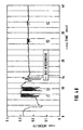
- Fig. 4B depicts a long term measuring result for a laser system 80 according to Fig. 1B.
- the gas analysis cell 70 is provided for monitoring a respiration gas for medical purposes. All system parameters of the laser system 80 are maintained substantially constant except of the pressure within the gas analysis cell 70 which is maintained substantially constant during the first fourteen minutes and dithered with a frequency of approximately 60 Hz after fourteen minutes.
- time periods T1, T2, T3 and T4 a respiration gas was directed through the gas analysis cell 70, thus leading to a significant variation of the resonator intensities during those periods of time.
- the variation of the resonator intensity has been considerably stabilized after fourteen minutes by dithering the pressure within the external cavity 90.
- the resonator intensity during the periods T3 and T4 has been dramatically stabilized with respect to the periods T1 and T2 without a dithering.
- the embodiment corresponding to the Figs. 4 might further comprise frequency-limiting devices 360 in order to limit the bandwidth of the laser beam 60.
- the frequency limitation either in Fig. 3A or in other embodiments according to Figs. 1, is not necessary for the purpose of the invention to stabilize the optical power of the laser beam 60 against (environmental) disturbances, but only provides a useful parameter required for certain applications such as Raman scattering demanding a certain (frequency) bandwidth of the laser beam 60.
Abstract
Description
- The present invention relates to a laser system comprising a gain medium for providing and amplifying a laser beam within an optical resonator.
- Molecules, and in particular gas molecules, are mainly investigated by spectroscopy. Two different spectroscopic methods, i.e. infrared absorption and Raman scattering, are generally applied for airway gas monitoring. The most common and widely spread measuring type is the infrared absorption, since it provides a robust and simple system with reliable accuracy. Disadvantageous, however, is that the infrared absorption is not flexible for upgrading to other molecules. Raman scattering overcomes that disadvantage because each molecule provides its own characteristic scattering signal. In addition and in contrast to the infrared absorption, the wavelength of the excitation light can be chosen flexibly. The drawback of the Raman scattering, however, lies in its minor effect, meaning that an excitation power of a light beam will create only a very low Raman signal (e.g. an excitation power of 1 W will create a Raman signal of 1 pW).
- For medical purposes, such as respiratory or anesthetic gas monitoring, Raman scattering has been investigated as shown e.g. by Van Wagenen et al in "Gas Analysis by Raman scattering", Journal of Clinical Monitoring, vol. 2 No. 4, Oct. 1986.
- Because of the minor effect in Raman scattering, the optical output power of the excitation light should be selected as high as possible. In addition, to achieve a good resolution of the molecule spectra, the excitation light source should be a narrow band source with a good wavelength and power stability. Thus, laser sources are commonly used as excitation light sources, whereby for reasons of compactness, lifetime and price, semiconductor lasers are normally superior to solid state or gas lasers. However, semiconductor lasers exhibit, in contrast to solid state and gas lasers, the disadvantage of a low internal circulating optical power and a low coupled out optical power.
- A known solution for increasing excitation power for Raman scattering is disclosed in US-A-5,153,671 and US-A-5,245,405 for a gas analyzing system. A gas analysis cell employing Raman scattering is positioned within a single optically resonant cavity. The gas flow is directed into the cavity and analyzed within the gas analysis cell. Fig. 1a shows in principle such a
laser system 10 in the gas analyzing system of US-A-5,153,671. Thelaser system 10 comprises alaser cavity 20 between afirst mirror 30 and asecond mirror 40. Again medium 50 provides and amplifies alaser beam 60 which serves as an excitation beam in agas analysis cell 70 within thelaser cavity 20. Thefirst mirror 30 may also be part of thegain medium 50. - In a more sophisticated solution for increasing excitation power, in particular when semiconductor lasers are used as excitation sources for Raman scattering, the optical output power of the excitation laser is coupled into an external resonator as shown e.g. in US-A-5,642,375 or US-A-5,684,623 by the same applicant. Fig. 1b shows in principle such a coupled
laser system 80. The coupledlaser system 80 comprises thelaser cavity 20 between thefirst mirror 30 and thesecond mirror 40 and thegain medium 50 providing and amplifying thelaser beam 60. Anexternal cavity 90 is provided between thesecond mirror 40 and athird mirror 95, and is optically coupled to thelaser cavity 20. Thelaser beam 60 serves as excitation beam in thegas analysis cell 70 within theexternal cavity 90. By applying low loss mirrors with different reflection coefficients for themirrors external cavity 90 can be achieved. For example, a 10 mWsemiconductor laser beam 60 is capable of pumping theexternal cavity 90 up to several hundreds of Watts. US-A-5,432,610 further discloses a passive, purely optical locking of a laser diode on an external resonator. - Using such an external pumped resonator, as depicted as the
laser system 80 in Fig. 1b, for probing an unknown gas sample in theexternal cavity 90 will in particular provide enough optical power to excite a Raman signal well above the sensitivity limit of optical sensors. Optical sensors can simply be photodiodes, charged coupled devices or other image sensors for more sophisticated applications. - As well in the single
cavity laser system 10 as in the coupledcavity laser system 80, thegas analysis cell 70 represents the principal possibility of probing a gas sample, whereby the gas sample can be analyzed in a specific (separated) environment or directly in the respective cavity. Probing the gas sample can either be accomplished 'offline', i.e. the gas sample is taken and analyzed later (e.g. in a defined environment), or 'online', i.e. the gas sample is directly provided to thegas analysis cell 70 and analyzed. The latter case, in particular, allows monitoring of a gas flow such as a respiratory or anesthetic gas. Online gas monitoring, however, requires an increased effort with respect to stabilizing the laser system. - If there are no changes of the applied active and passive components of the laser system,
e.g. laser system laser cavity 20 of Fig. 1A or in theexternal cavity 90 in Fig. 1B) will substantially remain at constant power. Thelight beam 60 circulating in thelaser cavity 20 and theexternal cavity 90 comprises one or more (longitudinal) optical modes determined by the components of the laser system and the specific environmental circumstances within the respective cavity/cavities. Associated with each optical mode are a defined wavelength and a defined roundtrip phase shift. Thegain medium 50 supports the optical mode(s) that match(es) the required wavelengths and provides the necessary phase, thus leading to a high intensity build-up light beam 60 at the supported optical mode(s). - It is to be understood that semiconductor type lasers generally only support one optical mode at a time, while other laser types (e.g. gas laser) may support more than one optical mode concurrently. For the sake of simplicity, only semiconductor type lasers, supporting only one optical mode at a time, shall be considered in the following. However, it is clear that the principals as illustrated herein are applicable for multi-mode concurrently supporting lasers accordingly.
- In the coupled cavity system of Fig. 1B, a locking mechanism between the two resonators has to take place. To achieve substantial amplification and stability in the external cavity, the feedback of the external cavity into the laser cavity has to be adjusted, so that the laser diode radiation emits coherent radiation with a bandwidth and a wavelength to actively support the
external cavity 90 at a cavity resonant frequency. This process is called hereinafter "optical locking". - When a change of the applied active and passive components (e.g. of the optical path length) of the laser system occurs and/or the environmental conditions change, the currently supported optical mode does not match anymore the required wavelength and phase shift, and the laser system has to 'find' another optical mode matching the changed resonating conditions within the laser system. Thus, the
light beam 60 can suddenly extinguish (albeit temporarily) until a new optical mode is built up fitting to the changed cavity properties. This leads to a (significant and in most cases unwanted) variation of the optical power of theoptical beam 60 over the time. - Fig. 2 shows an example of a variation of the optical power over the time in the
external cavity 90 in an arrangement according to Fig. 1B. The power variations in the measurement example of Fig. 2 were possibly induced by temperature or other environmental variations causing modifications in the optical lengths of thelaser system 80. When applied for Raman scattering, the power variation leads to different results for the Raman scattering measurement due to a variation in the exciting power. - A known possibility for avoiding environmental disturbances is disclosed in US-A-5,245,405 for the gas analyzing cell as discussed above. A pressure control system eliminates pressure variations in the gas cell regardless of changes in restriction, gas viscosity and barometric pressure. Maintaining a constant pressure in the gas cell makes the system more stabile, since optical alignment through the gas cell is sensitive to gas pressure. Other known solutions suggest to arrange mechanical pumps for providing the gas flow as far as possible away from the gas analyzing cell in order to reduce disturbances by the pump as much as possible. However, although all of those solutions refer to gas analyzing purposes, they have been proved unpractical in several cases since the gas flow, in particular for respiration gases, is hardly controllable and always provides a source of disturbances, e.g. due to variations in the gas compounds.
- A solution for an actively locked external
optical resonator 90 is an external servo control loop, which changes the characteristics of thelaser cavity 20 in a way that thiscavity 20 remains locked to a single external cavity mode with a constant optical power. Parameters to change the characteristics of thelaser cavity 20 are current and temperature of theactive laser medium 50 as well as mechanical changes of thelaser cavity 20. This solution, however, requires highly sophisticated countermeasures to ensure stabile conditions, and because of the necessary resolution, such a servo control loop can become very expensive and costly. - It is an object of the present invention to provide a laser system that is less sensitive for variations of the optical components and/or for environmental disturbances. The object is solved by the independent claims. Preferred embodiments are shown by the dependent claims.
- According to the invention, the laser system is actively forced to jump between different optical modes, or, in other words, the laser system comprises means for providing a plurality of different optical modes. In contrast to conventional laser systems wherein different optical modes randomly (i.e. passively) occur, the inventive laser system actively provides the plurality of different optical modes and thus forces the laser beam to (preferably continuously) jump between the provided optical modes.
- As long as the applied active and passive components of the laser system and/or the environmental conditions remain unchanged, the average optical power of the
laser beam 60 in the inventive laser system, forcing the laser beam to jump between different optical modes, is decreased with respect to the substantially constant (equilibrium state) optical power of the single opticalmode laser beam 60 in the conventional laser system. However, when the applied active and passive components of the laser system and/or the environmental conditions change, the optical power of thelaser beam 60 in the conventional laser system will suddenly dramatically decrease until a new optical mode has been 'found' and built up, thus leading to significant power variations. Since the laser system according to the invention already provides a plurality of optical modes, the likelihood for the inventive laser system to 'find' a 'new' matching optical mode is significantly increased, so that the inventive laser system will generally 'recover' much faster from variations of the optical components and/or environmental disturbances. Moreover, since the average optical power of the unchanged inventive laser system is generally lower than the (equilibrium state) optical power of the unchanged conventional laser system, and thus the differences in optical power due to disturbances are smaller in the inventive laser system, the optical power in the inventive laser system can be significantly stabilized. Thus, forcing the laser system to jump between different optical modes preferably much more frequent than 'disturbances' of the laser system occur allows stabilizing the optical power in the resonator. - In most laser systems, the amplification of the
laser beam 60 will be different for each optical mode. Therefore, the optical power might change from mode to mode. The optical power behavior of thelaser beam 60 can be further stabilized by increasing the number of actively induced jumps between optical modes, in particular with respect to power averaging periods of the laser system. In case of Raman applications, e.g. for respiratory or anesthetic gas monitoring, the number of induced jumps between optical modes is preferably selected to be large during a time period wherein the Raman spectrum is averaged. Thus, the average optical power during that time period can be stabilized. - There are several ways to actively force the laser system to jump between different optical modes, such as varying the phase of the light beam or varying the optical length of the laser system. Other possibilities might be applied accordingly, however, varying phase and/or optical length have been proved to be the most practical.
- Varying the phase of the laser, e.g. by adding phase to the light beam, can be achieved for example by varying (or dithering) the current and/or the temperature of a semiconductor laser as the
gain medium 50, or by varying the refractive index, and thus the phase of the light, by means of electrical or mechanical forces. The temperature variation of the semiconductor laser is preferably performed with the semiconductor directly mounted to a cooling and/or heating device. Phase changes of the semiconductor laser can thus be induced because the refractive index of the semiconductor laser is a strong function of the temperature. - Varying the optical length can be performed, for example, by varying (or dithering) the refractive index, e.g. by varying the cavity pressure or the physical cavity length(s), e.g. by moving one or more cavity mirrors or otherwise changing the mechanical length(s). The variation of the optical lengths in a coupled resonator system, as shown e.g. in Fig. 1B, can be executed in only one of the resonators and/or in all.
- In particular for varying the optical length, 'natural' or inherent sources of disturbances in the applied laser system can be intentionally used for actively forcing the laser system to jump between different optical modes. For example, in a laser system wherein a pump pumps a gas to be monitored to the
gas analysis cell 70, it can be made use of the inherent disturbances caused by the pumping for varying the cavity pressure. Whereas e.g. in US-A-5,245,405 the pump is deliberately arranged as far as possible away from thegas analysis cell 70 in order to avoid disturbances, the invention suggests e.g. to intentionally arrange a pump close(r) to thegas analysis cell 70 in a way that the laser system is to actively forced to jump between different optical modes. - It is clear that in a multi-cavity laser system wherein the optical length of the system is determined by a plurality of individual optical lengths, varying the optical length of the system can be accomplished by varying one or more of the individual optical lengths. That means that e.g. in a coupled laser system as depicted in Fig. 1b, the optical length can be changed as well of the buildup cavity (external cavity 90) as of the laser cavity 20 (e.g. as the cavity between the back mirror of the diode laser and the input mirror of the buildup cavity), or even both. This can be done, for example, by changing the refractive index of the gas in either one or both cavities.
- In strict contrast to conventional laser systems wherein the system is stabilized by (actively) carefully controlling the environment and restricting the bandwidth of the system to only one single mode, the laser system according to the invention is actively 'disturbed' so that the inventive laser system is forced to jump between optical modes and thus deliberately runs in a continuous multi-optical mode. This means that in case of (external) instabilities, the inventive laser system can jump to another stable mode to continue lasing, whereas in conventional laser systems lasing immediately will stop. Although the best performance (e.g. with respect to the achievable optical power in the cavity) of an optical laser system can be reached if only one single optical mode will be supported by the system, however, the inventive multi-optical-mode-system provides a higher overall stability, so that the requirements on environmental and mechanical stability as well as on optical filters can be reduced, with a significant impact on the price performance of the laser system e.g. for gas monitoring purposes.
- It has to be noted that the principles of the invention also apply for laser systems concurrently supporting a plurality of optical modes (e.g. gas lasers). In that case, the laser system will be forced to concurrently jump between one or more different optical modes.
- In a preferred embodiment, the numbers of optical modes supported by the inventive laser system is reduced to a discrete number of optical modes in order to restrict the bandwidth of the laser system. This can be achieved e.g. by providing respective wavelength filters like prism, grating and/or etalon. It has to be understood that the requirements of stability and bandwidth of the laser system are contradicting, so that a certain tradeoff has to be found for each application. In a specific embodiment employing Raman scattering, the provision of four optical modes (which can lase) has been found to provide a good and acceptable compromise between those requirements.
- Other objects and many of the attendant advantages of the present invention will be readily appreciated and become better understood by reference to the following detailed description when considering in connection with the accompanied drawings. Features that are or can be built up substantially equally or similarly are referred to with the same reference sign.
- Figs. 1a and 1b
- show laser system in the gas analyzing system as known in the art,
- Fig. 2
- shows an example of a variation of the optical power over the time
in the
external cavity 90 in an arrangement according to Fig. 1B, - Figs. 3
- depict a first embodiment of the invention and corresponding measuring results, and
- Figs. 4
- depict the behavior of the optical power in the external resonator over the time and a long term measuring result in a laser system according to the invention.
- Fig. 3a shows a first embodiment of the invention wherein varying the phase of the laser can be achieved by varying the current and/or temperature of a semiconductor laser as the
gain medium 50. The embodiment of Fig. 3a is based on the embodiment of Fig. 5 as disclosed in US-A-5,642,375 by the same applicant and one of the present inventors. The shown embodiment employs a coupledlaser system 80 as depicted in Fig. 1B, however, thelaser system 10 according to Fig. 1A can be employed accordingly. - In Fig. 3a, the
gain medium 50 is incorporated into the structure of asemiconductor diode laser 300. The back facet of thelaser 300 is coated to be reflective and forms thesurface 30. Anemission facet 310 of thediode laser 300 is anti-reflection (AR) coated, with reflectivity preferably in the range of less than 10-3.Reflective surfaces surfaces 320 and 330). Mode matching optics 340 (e.g. lenses and/or prisms) well known to those skilled in the art, can be used to spatially match the diode emission into theexternal cavity 90. Asurface 350 of the mirror (substrate) 40 facing thelaser cavity 20 is preferably anti-reflection coated with a reflectivity in the range about 0.04 to 0.001. Alternatively, thesurface 350 can be a chamfer at an angle with thelight path 60 to reduce its light reflection into the gain medium. - A frequency-limiting
device 360 is preferably placed between themode matching optics 340 and themirror 40. In this way, the frequency-limitingdevice 360 produces the most effect using a minimum number of components. Such a system may be constructed using a Philips CQL 801D diode laser as thegain medium 50, having itsemission facet 310 coated to have a reflectivity in the range of 10-5 to 10-4. Themode matching optics 340 preferably consists of an anti-reflection (AR) coated lens with a numerical aperture (NA) of 0.48 and focal length of 4.8 mm, an anamorphic prism pair (3:1), and a 25 cm focal length lens. Thesurfaces external cavity 90 may be 10 cm. Other details of the preferred embodiments can be obtained from US-A-5,642,375. - The frequency-limiting
device 360 in Fig. 3 is employed to filter out the undesirable frequencies in order to reduce the frequency bandwidth of thelaser beam 60. The frequency-limitingdevices 360 may include one or a combination of gratings, etalon, lyot filters, or dielectric stack filters. The rear surface of the diodelaser gain medium 300 may be coated with a distributed Bragg reflector, which also limits the allowed frequencies in the laser system. Examples of applicable frequency-limitingdevices 360 are described in great detail in US-A-5,642,375. - Figs. 3B and 3C depict measuring results derived from an embodiment according to Fig. 3A. The average power that leaked out of the
external cavity 90 is depicted on the Y-axis and was measured as a function (depicted on the X-axis) of the temperature (Fig. 3B) or the current (Fig. 3C) of the diodelaser gain medium 300. - Dashed line 370 in Fig. 3B depicts the behavior of the power leakage versus diode temperature without dithering the current of the
diode 300.Straight line 375, in contrast thereto, depicts a power versus temperature curve, whereby the current of thediode 300 has been dithered with a 100 Hz triangle wave with 16 mA peak-to-peak. Bothlines 375 and 380 were measured for a current of thediode 300 of 86 mA. - Fig. 3C depicts power versus diode current behaviors. Dashed line 380 represents the power behavior when the diode current is not dithered.
Lines - The effect of the dithering becomes clear from Figs. 3B and 3C. In both Figs. 3B and 3C, without dithering the average power varied greatly with environmental changes (i.e. diode current and temperature). With dithering, the changes could be greatly smoothed out (particularly evident in Fig. 3B).
- In another preferred embodiment, the optical length of the optical resonator (e.g. in a laser system according to Fig. 1A or 1B) is varied. Figs. 4A and 4B display measuring results, wherein the refractive index of the laser cavity has been modified by varying the cavity pressure. It is to be understood that in case of coupled laser systems, a variation of the refractive index of each laser cavity will also vary the refractive index of the coupled laser system.
- Fig. 4A shows the behavior of the optical power in the external resonator over the time in a
laser system 80 according to Fig. 1B. In contrast to the measuring result as depicted in Fig. 2 for the same laser system, the refractive index of the optical resonator length has been varied by means of a 60 Hz air pressure pulsation within theexternal cavity 90. By comparing Fig. 4A with Fig. 2, it becomes apparent that the resonator intensity can be significantly stabilized by dithering the cavity pressure. - Fig. 4B depicts a long term measuring result for a
laser system 80 according to Fig. 1B. Thegas analysis cell 70 is provided for monitoring a respiration gas for medical purposes. All system parameters of thelaser system 80 are maintained substantially constant except of the pressure within thegas analysis cell 70 which is maintained substantially constant during the first fourteen minutes and dithered with a frequency of approximately 60 Hz after fourteen minutes. During time periods T1, T2, T3 and T4, a respiration gas was directed through thegas analysis cell 70, thus leading to a significant variation of the resonator intensities during those periods of time. As apparent from Fig. 4B, the variation of the resonator intensity has been considerably stabilized after fourteen minutes by dithering the pressure within theexternal cavity 90. In particular during the periods of time wherein the respiration gas was directed through thegas analysis cells 70, the resonator intensity during the periods T3 and T4 has been dramatically stabilized with respect to the periods T1 and T2 without a dithering. - The embodiment corresponding to the Figs. 4 might further comprise frequency-limiting
devices 360 in order to limit the bandwidth of thelaser beam 60. It is to be understood that the frequency limitation, either in Fig. 3A or in other embodiments according to Figs. 1, is not necessary for the purpose of the invention to stabilize the optical power of thelaser beam 60 against (environmental) disturbances, but only provides a useful parameter required for certain applications such as Raman scattering demanding a certain (frequency) bandwidth of thelaser beam 60.
Claims (11)
- A laser system (10; 80) comprising a gain medium (50) for providing and amplifying a laser beam (60) within an optical resonator (20, 90), characterized by means for actively providing a plurality of different optical modes for stabilizing the laser beam (60).
- The laser system of claim 1, characterized in that the mode-providing means comprises means for forcing the laser beam (60) to jump between different optical modes more frequent than environmental disturbances occur.
- The laser system of claim 1 or 2, characterized in that the mode-providing means comprises means for forcing the laser beam (60) to continuously jump between different optical modes.
- The laser system according to any one of the above claims, characterized by comprising means for actively inducing jumps between optical modes with frequencies greater than power averaging frequencies for monitoring an average power of the laser beam (60) in the laser system.
- The laser system of claim 4, characterized in that the number of induced jumps between optical modes is large during a time period wherein a Raman spectrum derived from the laser beam (60) is averaged.
- The laser system according to any one of the above claims, characterized in that the mode-providing means comprises means for varying the phase of the laser beam (60) and/or means for varying the optical length of the optical resonator (20, 90).
- The laser system of claim 6, characterized in that the means for varying the phase of the laser beam (60) comprises means for varying a current and/or a temperature of the gain medium (50), and/or means for varying a refractive index and thus the phase of the laser beam (60).
- The laser system of claim 6 or 7, characterized in that the means for varying the optical length of the optical resonator (20, 90) comprises means for varying the refractive index, preferably means for varying pressure and/or physical length of the optical resonator (20, 90).
- A method for stabilizing a laser beam (60) in a laser system (10; 80) comprising a gain medium (50) for providing and amplifying a laser beam (60) within an optical resonator (20, 90), characterized by actively providing a plurality of different optical modes for stabilizing the laser beam (60).
- The method of claim 9, characterized by forcing the laser beam (60) to jump between different optical modes more frequent than environmental disturbances occur.
- A gas monitoring system, preferably for monitoring a respiration and/or anaesthetic gas, comprising a laser system (10; 80) according to any one of the claims 1-8 for providing a Raman spectrum of the gas to be monitored.
Applications Claiming Priority (2)
| Application Number | Priority Date | Filing Date | Title |
|---|---|---|---|
| US227105 | 1999-01-07 | ||
| US09/227,105 US6222860B1 (en) | 1999-01-07 | 1999-01-07 | Laser system tolerating disturbances using multiple modes |
Publications (2)
| Publication Number | Publication Date |
|---|---|
| EP1018791A1 true EP1018791A1 (en) | 2000-07-12 |
| EP1018791B1 EP1018791B1 (en) | 2003-05-07 |
Family
ID=22851763
Family Applications (1)
| Application Number | Title | Priority Date | Filing Date |
|---|---|---|---|
| EP99117083A Expired - Lifetime EP1018791B1 (en) | 1999-01-07 | 1999-08-31 | Laser system tolerating disturbances |
Country Status (4)
| Country | Link |
|---|---|
| US (1) | US6222860B1 (en) |
| EP (1) | EP1018791B1 (en) |
| JP (1) | JP2000208865A (en) |
| DE (1) | DE69907618T2 (en) |
Families Citing this family (7)
| Publication number | Priority date | Publication date | Assignee | Title |
|---|---|---|---|---|
| WO2004070893A2 (en) * | 2003-02-05 | 2004-08-19 | Gws-Photonics Ltd. | External cavity tunable laser and control |
| CN100353622C (en) * | 2005-01-27 | 2007-12-05 | 中国计量学院 | Method and device for a pair of wave-length rotary Raman laser source with NO2 differential absorbing detection |
| DE102005040661B3 (en) * | 2005-08-26 | 2006-12-28 | Leica Microsystems Semiconductor Gmbh | Coordinates measuring device e.g. for determining position of moveable table, has measuring mirror installed at table with reflector surface of mirror stands parallel to direction of table |
| WO2016125155A1 (en) * | 2015-02-02 | 2016-08-11 | Wi-Charge Ltd. | Distributed coupled resonator laser |
| US10527492B2 (en) * | 2017-05-16 | 2020-01-07 | Li-Cor, Inc. | Mode matching method for absorption spectroscopy systems |
| FR3091925B1 (en) | 2019-01-18 | 2021-01-29 | Ap2E | Optical feedback resonant optical cavity system, suitable for the detection of gas traces by Raman spectrometry |
| US10847948B2 (en) * | 2019-03-13 | 2020-11-24 | King Fahd University Of Petroleum And Minerals | Self-injection locked tunable laser |
Citations (5)
| Publication number | Priority date | Publication date | Assignee | Title |
|---|---|---|---|---|
| US4972424A (en) * | 1989-05-17 | 1990-11-20 | Hughes Aircraft Company | Automatic dither stabilization of a laser cavity |
| US5065401A (en) * | 1991-02-26 | 1991-11-12 | Spectra Diode Laboratories, Inc. | Pulse jitter reduction method for a laser diode or array |
| WO1996000997A1 (en) * | 1994-06-28 | 1996-01-11 | Sdl, Inc. | Fibre grating stabilized diode laser |
| US5511087A (en) * | 1993-03-19 | 1996-04-23 | Fujitsu Limited | Method and device for controlling semiconductor laser |
| US5684623A (en) * | 1996-03-20 | 1997-11-04 | Hewlett Packard Company | Narrow-band tunable optical source |
Family Cites Families (10)
| Publication number | Priority date | Publication date | Assignee | Title |
|---|---|---|---|---|
| JPS57124493A (en) * | 1981-01-26 | 1982-08-03 | Mitsubishi Electric Corp | Coupler for semiconductor laser and optical fiber |
| US4622672A (en) * | 1984-01-20 | 1986-11-11 | At&T Bell Laboratories | Self-stabilized semiconductor lasers |
| US5245405A (en) | 1990-05-11 | 1993-09-14 | Boc Health Care, Inc. | Constant pressure gas cell |
| US5153671A (en) | 1990-05-11 | 1992-10-06 | Boc Health Care, Inc. | Gas analysis system having buffer gas inputs to protect associated optical elements |
| US5432610A (en) | 1994-04-15 | 1995-07-11 | Hewlett-Packard Company | Diode-pumped power build-up cavity for chemical sensing |
| JPH08167875A (en) * | 1994-12-14 | 1996-06-25 | Sony Corp | Optical spatial communication device |
| US5642375A (en) | 1995-10-26 | 1997-06-24 | Hewlett-Packard Company | Passively-locked external optical cavity |
| DE19642409B4 (en) * | 1995-10-26 | 2011-05-12 | Agilent Technologies, Inc. (n.d.Ges.d. Staates Delaware), Santa Clara | "External Resonator Laser System" |
| US6058128A (en) * | 1996-03-25 | 2000-05-02 | Sdl, Inc. | Apparatus for providing a stabilized laser source |
| US5914972A (en) * | 1997-03-24 | 1999-06-22 | Sdl, Inc. | Thermal compensators for waveguide DBR laser sources |
-
1999
- 1999-01-07 US US09/227,105 patent/US6222860B1/en not_active Expired - Lifetime
- 1999-08-31 EP EP99117083A patent/EP1018791B1/en not_active Expired - Lifetime
- 1999-08-31 DE DE69907618T patent/DE69907618T2/en not_active Expired - Lifetime
- 1999-12-14 JP JP11353867A patent/JP2000208865A/en active Pending
Patent Citations (5)
| Publication number | Priority date | Publication date | Assignee | Title |
|---|---|---|---|---|
| US4972424A (en) * | 1989-05-17 | 1990-11-20 | Hughes Aircraft Company | Automatic dither stabilization of a laser cavity |
| US5065401A (en) * | 1991-02-26 | 1991-11-12 | Spectra Diode Laboratories, Inc. | Pulse jitter reduction method for a laser diode or array |
| US5511087A (en) * | 1993-03-19 | 1996-04-23 | Fujitsu Limited | Method and device for controlling semiconductor laser |
| WO1996000997A1 (en) * | 1994-06-28 | 1996-01-11 | Sdl, Inc. | Fibre grating stabilized diode laser |
| US5684623A (en) * | 1996-03-20 | 1997-11-04 | Hewlett Packard Company | Narrow-band tunable optical source |
Also Published As
| Publication number | Publication date |
|---|---|
| DE69907618D1 (en) | 2003-06-12 |
| EP1018791B1 (en) | 2003-05-07 |
| JP2000208865A (en) | 2000-07-28 |
| US6222860B1 (en) | 2001-04-24 |
| DE69907618T2 (en) | 2004-03-11 |
Similar Documents
| Publication | Publication Date | Title |
|---|---|---|
| JP4992073B2 (en) | Phase control of an external cavity tunable laser. | |
| US6594022B1 (en) | Wavelength reference device | |
| WO1999060677A1 (en) | Fiber grating coupled light source capable of tunable, single frequency operation | |
| US20040091002A1 (en) | Double etalon optical wavelength reference device | |
| EP0979547B1 (en) | Tunable external cavity diode laser | |
| US6222860B1 (en) | Laser system tolerating disturbances using multiple modes | |
| EP1745532B1 (en) | Stabilized laser source with very high relative feedback and narrow bandwidth | |
| US7130322B2 (en) | Wavelength tunable laser and method of controlling the same | |
| US6996144B2 (en) | Wavelength stabilization of tunable lasers by current modulation | |
| JP2000208865A5 (en) | ||
| JP7295127B2 (en) | External cavity quantum cascade laser | |
| US20070030877A1 (en) | Apparatus and method for monitoring power of a UV laser | |
| KR20210113306A (en) | Resonant optical cavity system with optical feedback suitable for trace gas detection by Raman spectroscopy | |
| EP1597803A1 (en) | Laser source with high relative feedback and method for making such a laser source | |
| US11035992B1 (en) | System and method for limiting the effective coherence length of a solid-state laser in holographic recording | |
| US20090310634A1 (en) | Stabilized laser source with very high relative feedback and narrow bandwidth | |
| CA2381658A1 (en) | Optical fiber wavelength reference device | |
| JP2008543101A (en) | Ultra-low noise semiconductor laser | |
| JP7476472B2 (en) | Method and apparatus for laser stabilization - Patents.com | |
| US20210344167A1 (en) | System and method for optical feedback stabilized semiconductor frequency combs | |
| Luhs et al. | CW molecular iodine laser pumped with a low power DPSSL | |
| Kawai et al. | Mode-hop-free operation of a distributed Bragg reflector diode laser in an external fiber-cavity configuration | |
| Brasunas | A simple etalon-stabilized visible laser diode | |
| Jay et al. | Control platform for fiber laser management | |
| JP2000031602A (en) | Semiconductor light emitting module |
Legal Events
| Date | Code | Title | Description |
|---|---|---|---|
| PUAI | Public reference made under article 153(3) epc to a published international application that has entered the european phase |
Free format text: ORIGINAL CODE: 0009012 |
|
| 17P | Request for examination filed |
Effective date: 20000303 |
|
| AK | Designated contracting states |
Kind code of ref document: A1 Designated state(s): DE FR GB |
|
| AX | Request for extension of the european patent |
Free format text: AL;LT;LV;MK;RO;SI |
|
| AKX | Designation fees paid |
Free format text: DE FR GB |
|
| RAP1 | Party data changed (applicant data changed or rights of an application transferred) |
Owner name: AGILENT TECHNOLOGIES, INC. |
|
| RAP1 | Party data changed (applicant data changed or rights of an application transferred) |
Owner name: AGILENT TECHNOLOGIES INC. |
|
| RAP1 | Party data changed (applicant data changed or rights of an application transferred) |
Owner name: AGILENT TECHNOLOGIES INC. A DELAWARE CORPORATION |
|
| RAP1 | Party data changed (applicant data changed or rights of an application transferred) |
Owner name: AGILENT TECHNOLOGIES, INC. (A DELAWARE CORPORATION |
|
| 17Q | First examination report despatched |
Effective date: 20020110 |
|
| GRAG | Despatch of communication of intention to grant |
Free format text: ORIGINAL CODE: EPIDOS AGRA |
|
| GRAG | Despatch of communication of intention to grant |
Free format text: ORIGINAL CODE: EPIDOS AGRA |
|
| GRAH | Despatch of communication of intention to grant a patent |
Free format text: ORIGINAL CODE: EPIDOS IGRA |
|
| GRAH | Despatch of communication of intention to grant a patent |
Free format text: ORIGINAL CODE: EPIDOS IGRA |
|
| GRAA | (expected) grant |
Free format text: ORIGINAL CODE: 0009210 |
|
| AK | Designated contracting states |
Designated state(s): DE FR GB |
|
| REG | Reference to a national code |
Ref country code: GB Ref legal event code: FG4D |
|
| REF | Corresponds to: |
Ref document number: 69907618 Country of ref document: DE Date of ref document: 20030612 Kind code of ref document: P |
|
| RAP2 | Party data changed (patent owner data changed or rights of a patent transferred) |
Owner name: KONINKLIJKE PHILIPS ELECTRONICS N.V. |
|
| ET | Fr: translation filed | ||
| PLBE | No opposition filed within time limit |
Free format text: ORIGINAL CODE: 0009261 |
|
| STAA | Information on the status of an ep patent application or granted ep patent |
Free format text: STATUS: NO OPPOSITION FILED WITHIN TIME LIMIT |
|
| 26N | No opposition filed |
Effective date: 20040210 |
|
| REG | Reference to a national code |
Ref country code: GB Ref legal event code: 732E |
|
| REG | Reference to a national code |
Ref country code: FR Ref legal event code: TP |
|
| REG | Reference to a national code |
Ref country code: FR Ref legal event code: CD Owner name: KONINKLIJKE PHILIPS ELECTRONICS NV, NL Effective date: 20141126 Ref country code: FR Ref legal event code: CA Effective date: 20141126 |
|
| REG | Reference to a national code |
Ref country code: FR Ref legal event code: PLFP Year of fee payment: 18 |
|
| REG | Reference to a national code |
Ref country code: DE Ref legal event code: R082 Ref document number: 69907618 Country of ref document: DE Representative=s name: MEISSNER BOLTE PATENTANWAELTE RECHTSANWAELTE P, DE |
|
| REG | Reference to a national code |
Ref country code: FR Ref legal event code: PLFP Year of fee payment: 19 |
|
| PGFP | Annual fee paid to national office [announced via postgrant information from national office to epo] |
Ref country code: GB Payment date: 20170830 Year of fee payment: 19 Ref country code: FR Payment date: 20170828 Year of fee payment: 19 |
|
| PGFP | Annual fee paid to national office [announced via postgrant information from national office to epo] |
Ref country code: DE Payment date: 20171030 Year of fee payment: 19 |
|
| REG | Reference to a national code |
Ref country code: DE Ref legal event code: R119 Ref document number: 69907618 Country of ref document: DE |
|
| GBPC | Gb: european patent ceased through non-payment of renewal fee |
Effective date: 20180831 |
|
| PG25 | Lapsed in a contracting state [announced via postgrant information from national office to epo] |
Ref country code: DE Free format text: LAPSE BECAUSE OF NON-PAYMENT OF DUE FEES Effective date: 20190301 |
|
| PG25 | Lapsed in a contracting state [announced via postgrant information from national office to epo] |
Ref country code: FR Free format text: LAPSE BECAUSE OF NON-PAYMENT OF DUE FEES Effective date: 20180831 |
|
| PG25 | Lapsed in a contracting state [announced via postgrant information from national office to epo] |
Ref country code: GB Free format text: LAPSE BECAUSE OF NON-PAYMENT OF DUE FEES Effective date: 20180831 |