EP1017241A2 - A method for compensating image color when adjusting the contrast of a digital color image - Google Patents
A method for compensating image color when adjusting the contrast of a digital color image Download PDFInfo
- Publication number
- EP1017241A2 EP1017241A2 EP99204060A EP99204060A EP1017241A2 EP 1017241 A2 EP1017241 A2 EP 1017241A2 EP 99204060 A EP99204060 A EP 99204060A EP 99204060 A EP99204060 A EP 99204060A EP 1017241 A2 EP1017241 A2 EP 1017241A2
- Authority
- EP
- European Patent Office
- Prior art keywords
- tone scale
- color
- scale function
- output
- determining
- Prior art date
- Legal status (The legal status is an assumption and is not a legal conclusion. Google has not performed a legal analysis and makes no representation as to the accuracy of the status listed.)
- Granted
Links
Images


Classifications
-
- H—ELECTRICITY
- H04—ELECTRIC COMMUNICATION TECHNIQUE
- H04N—PICTORIAL COMMUNICATION, e.g. TELEVISION
- H04N5/00—Details of television systems
- H04N5/44—Receiver circuitry for the reception of television signals according to analogue transmission standards
- H04N5/57—Control of contrast or brightness
-
- H—ELECTRICITY
- H04—ELECTRIC COMMUNICATION TECHNIQUE
- H04N—PICTORIAL COMMUNICATION, e.g. TELEVISION
- H04N9/00—Details of colour television systems
- H04N9/64—Circuits for processing colour signals
- H04N9/643—Hue control means, e.g. flesh tone control
Definitions
- the invention relates generally to the field of digital color image processing and, more particularly, for compensating the image color differences for the applied luminance tone scale.
- the first method involves applying the tone scale function to each of the color signals of the original image. This may be implemented by applying a tone scale function Look-Up-Table to each of the red, green, and blue channels of an image independently.
- tone scale application by this method has a color characteristic in addition to the modification of the overall image contrast.
- the image processed by a tone scale function in the manner described will effect each pixel's hue and saturation.
- a second method of tone scale application involves rotating a color image into a space consisting of a luminance signal and several chrominance channels.
- the tone scale function is then applied only to the luminance channel.
- the processed image is obtained by applying an inverse matrix to produce transformed red, green, and blue pixel values. This method preserves the original chrominance signal at each pixel. However, because the luminance contrast was modified and the chrominance contrast was preserved, the color saturation of the resulting image may appear artificial and unnatural.
- Viggiano and Wang proposed (1992 TAGA Proceedings: A Comparison of Algorithms for Mapping Color Between Media of Differing Luminance Ranges , pp. 959-974) a method of scaling the chroma signal of a digital color image by a factor midway between unity and the ratio of the L* range of the reproduction and the original.
- this solution does not anticipate tone scale functions that vary the level of compression dependent upon the intensity of the input.
- a single factor that scales the chroma signal of the input image is inappropriate for a wide range of possible tone scale functions.
- Wada describes a method to correct color saturation when compressing the dynamic range of an image.
- this method once again determines the correction factor based upon the relationship of the input image dynamic range and the output image dynamic range.
- Hickman describes a method of modifying the luminance signal of an input image, then "multiplying the color components by a transfer ratio of modified luminance to unmodified luminance to obtain modified color components.”
- this method again does not consider that a tone scale function may consist of several ranges of varying level of contrast compression or enhancement.
- the object of the present invention is directed to providing a superior method of compensating the color saturation characteristics of a digital color image for the application of a tone scale function.
- the invention resides in the steps of:(a) receiving a tone scale function; (b) calculating a local slope of the tone scale function for each pixel of the digital color image; (c) calculating a color saturation signal from the digital color image, and (d) adjusting the color saturation signal of the digital color image for each of the pixels based on the calculated local slope.
- Fig. 1 there is illustrated an overview of the present invention. It is instructive to note that the present invention utilizes a digital color image that is typically a two-dimensional array of red, green, and blue pixel values. The description of the present invention is applicable to an image of any resolution.
- the purpose of the present invention is the modification of the color saturation characteristics of a color image in accordance with the luminance contrast modification.
- the color saturation characteristics of a color image may be represented by a color saturation signal.
- color saturation signals may be calculated in a number of ways. For example, as one calculation of a color saturation signal, color difference signals may be calculated simply by implementing matrix multiplication on pixel values of the original image. Color difference signals refer to the difference of a color channel to a reference channel. A three channel color image consisting of a red, green, and blur channels may be convened to a three channel image consisting of a luminance channel and two color difference channels by matrix multiplication.
- a single color saturation signal could be created by converting the two color difference signals to polar form by calculating an angle and a radius.
- the calculation of polar coordinates from rectangular coordinates is well known in the art and will not be further described.
- the radius of the polar representation of the color difference signals represents the color saturation signal.
- the method of the present invention could be performed with equal success on such a color saturation measure.
- the preferred embodiment of the present invention modifies the color difference signals as a means of modifying the color saturation characteristics.
- the input image is passed into the color difference adjuster 10.
- the color difference adjuster adjusts the relative color difference of each pixel in the input image in accordance to a provided tone scale function, as will be further described. It is necessary to note that the provided tone scale function may be implemented as a LUT, or may be the implied tonal response of a device that resides in the imaging chain.
- the output of the color difference adjuster is a transformed color image with color difference signals modified to compensate for the tone scale function.
- Fig. 2 therein is illustrated an exploded view of the color difference adjuster 10.
- the preferred embodiment shown in Fig. 2 assumes that the input image has not yet been modified by the given tone scale.
- An alternative embodiment will describe a method of application of the present invention on an image that has already had the tone scale applied to the luminance channel of the image at the time the image is passed to the color difference adjuster 10.
- the color difference signals as well as a luminance signal of the original color image are computed by the color difference transformer 20.
- the computation of the color difference signals by the color difference transformer may be performed by a matrix operation. For example, in the preferred embodiment, a luminance signal and two color difference signals may be determined for each pixel of the input image by the following matrix transform: Where:
- a luminance signal and three color difference signals may be determined for each signal, also with a matrix transform:
- each color difference signal is a linear combination of the red, green, and blue intensities of a pixel of the original image.
- the coefficients are such that the sum of the weights of the red, green, and blue coefficients must sum to 0.
- the given tone scale function is input to the slope calculator 30.
- the original red, green, and blue pixel values are also input to the slope calculator 30.
- the purpose of the slope calculator 30 is to compute the local slope of the given tone scale function, evaluated for the current pixel being processed.
- the output of the slope calculator 30 is passed to the adjustment factor calculator 40.
- the purpose of the adjustment factor calculator 40 is to determine a scaling factor for the color difference signals, based upon the local slope of the tone scale function as determined by the slope calculator 20.
- H i K ⁇ i ( f '- f ' 0 ) + f ' 0
- K color position weight
- the value of the color position weight K ranges from 0.0 to 1.0.
- the color position weight K enables the method of the present invention to allow the calculation of the adjustment factor H i to vary based upon the color characteristics of the pixel.
- K is a function of the luminance L and color difference C i values.
- Fig. 5 illustrates the use of a two-dimensional LUT 90 as a method of determining the value of K for each pixel. As shown in Fig. 5, the value of the color position weight K is shown to be dependent upon the color differences C i .
- This formulation of the color position weight K allows the method of the present invention to adjust the color difference values of pixels that are colored similarly to human flesh (K ⁇ 1.0), but preserve the original color difference values for pixels that are colored differently than human flesh (K ⁇ 0.0).
- This embodiment has been found to be advantageous to avoid desaturation of saturated objects such as sky, while allowing for the required modifications to the color difference values of flesh color pixels.
- a color position weight K may take many forms (such as introducing a luminance L value dependence into the determination of the color position weight K) without significantly deviating from the scope of the present invention.
- the output of the adjustment factor calculator 40 is passed to the multiplier 50.
- the purpose of the multiplier 50 is to scale each of the color difference signals by the output of the adjustment factor calculator 40.
- the luminance signal L calculated by the color difference transformer may be passed to the tone scale applicator 60.
- the given tone scale function may be applied to the image as a processing step following the application of the present invention.
- the tone scale applicator 60 modifies the luminance signal with the application of the given tone scale function.
- a Look-Up-Table may be implemented in order to apply the tone scale function.
- the method of U.S. patent 5,012,333 may be implemented. In either of these cases, the signal output of the tone scale applicator is a function of the input luminance signal.
- L p f(L)
- the compensated color difference signals and the luminance signal are passed to the RGB reconstructor 70.
- the RGB reconstructor 70 converts the image from a luminance signal and a plurality of color difference signals to an image containing at each pixel location red, green, and blue intensity values. This conversion is accomplished by the use of a matrix. If a three by three matrix was used by the color difference transformer 20, then the conversion performed by the RGB reconstructor is to simply multiply a vector of the luminance signal and two color difference signals by the inverse of the matrix used by the color difference transformer 20. In the preferred embodiment, Where:
- the RGB reconstructor 70 performs the following operation in order to produce R p , G p , and B p .
- the product of the matrix used by the RGB reconstructor 70 and the matrix used by the color difference transformer 20 is an identity matrix.
- the R p , G p , and B p signals are output from the RGB reconstructor 70.
- these three processed color planes form a processed image in which the color difference signals have been modified in accordance with the luminance modification by a given tone scale function.
- the image input to the color difference adjuster 10 may already have been modified by the given tone scale function.
- the given tone scale function may have been applied to either each of the color channels of the input image or to only the luminance channel of the given image.
- the image input to the color difference adjuster 10 is first passed to the color difference transformer 20 in order to generate a luminance signal and several color difference signals.
- the color difference signals output from the color difference transformer 20 are passed to the multiplier, which scales each of the color difference channels by a factor output by the adjustment factor calculator 40, as previously described in the preferred embodiment.
- the modified color difference channels output from the multiplier 50 are, along with the luminance channel output from the color difference transformer 20, passed to the RGB reconstructor 70.
- the output of the RGB reconstructor 70 is a processed image with the color differences appropriately adjusted for the given tone scale function.
- the tone scale function that has already been applied to each of the color channels of the input image is passed to the inverse function generator 80.
- the inverse function generator constructs the inverse of the tone scale function. Finding the inverse of a function is a well known technique in mathematics and will not be further discussed.
- the inverse tone scale function generated by the inverse function generator 80 is then passed to the slope calculator 30, the operation of which has previously been described.
- the output of the slope calculator is passed to the adjustment factor calculator 40, the operation of which has also been described.
- Fig. 4 may be implemented to modify the color difference signals of the input image in an appropriate manner.
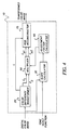
- Fig.4 The alternative embodiment illustrated by Fig.4 is identical to the preferred embodiment with the exception that there is no option to apply the given tone scale function to the luminance signal of the input image by the tone scale applicator 60 shown in Fig. 2.
- an additional tone scale applicator 60 would be redundant and was thus omitted from the alternative embodiment as illustrated in Fig. 4.
- aspects of the invention include the method further comprising the step of providing a color position weight based upon the pixel value of the original digital color image; and the method wherein the step of adjusting the color saturation signal of the digital color image is dependent upon both the calculated local slope and the color position weight.
Abstract
Description
- The invention relates generally to the field of digital color image processing and, more particularly, for compensating the image color differences for the applied luminance tone scale.
- There exist in the prior art several methods of applying a tone scale function to a color image. The first method involves applying the tone scale function to each of the color signals of the original image. This may be implemented by applying a tone scale function Look-Up-Table to each of the red, green, and blue channels of an image independently. In general, tone scale application by this method has a color characteristic in addition to the modification of the overall image contrast. The image processed by a tone scale function in the manner described will effect each pixel's hue and saturation.
- A second method of tone scale application involves rotating a color image into a space consisting of a luminance signal and several chrominance channels. The tone scale function is then applied only to the luminance channel. The processed image is obtained by applying an inverse matrix to produce transformed red, green, and blue pixel values. This method preserves the original chrominance signal at each pixel. However, because the luminance contrast was modified and the chrominance contrast was preserved, the color saturation of the resulting image may appear artificial and unnatural.
- In an effort to address this problem, Viggiano and Wang proposed (1992 TAGA Proceedings: A Comparison of Algorithms for Mapping Color Between Media of Differing Luminance Ranges, pp. 959-974) a method of scaling the chroma signal of a digital color image by a factor midway between unity and the ratio of the L* range of the reproduction and the original. However, this solution does not anticipate tone scale functions that vary the level of compression dependent upon the intensity of the input. Thus, a single factor that scales the chroma signal of the input image is inappropriate for a wide range of possible tone scale functions.
- In addition, in U.S. Patent No. 5,446,504, Wada describes a method to correct color saturation when compressing the dynamic range of an image. However, this method once again determines the correction factor based upon the relationship of the input image dynamic range and the output image dynamic range.
- In addition, in U.S. Patent No. 5,638,138, Hickman describes a method of modifying the luminance signal of an input image, then "multiplying the color components by a transfer ratio of modified luminance to unmodified luminance to obtain modified color components." However, this method again does not consider that a tone scale function may consist of several ranges of varying level of contrast compression or enhancement.
- Thus, none of the methods described in the prior art have determined a specific color adjustment factor based upon both the intensity values of the pixel being processed and the given tone scale function. Consequently, there exists a need for a method of adjusting the color saturation of each image pixel by a factor related to the local slope of the given tone scale function.
- The object of the present invention is directed to providing a superior method of compensating the color saturation characteristics of a digital color image for the application of a tone scale function. Briefly summarized, according to one aspect of the present invention, the invention resides in the steps of:(a) receiving a tone scale function; (b) calculating a local slope of the tone scale function for each pixel of the digital color image; (c) calculating a color saturation signal from the digital color image, and (d) adjusting the color saturation signal of the digital color image for each of the pixels based on the calculated local slope.
- These and other aspects, objects, features and advantages of the present invention will be more clearly understood and appreciated from a review of the following detailed description of the preferred embodiments and appended claims, and by reference to the accompanying drawings.
-
- Fig. 1 is a block diagram illustrating an overview of the present invention;
- Fig. 2 is an exploded view of the color difference adjuster of Fig. 1;
- Fig. 3 is an exploded view of an alternative embodiment of the color difference adjuster of Fig. 1;
- Fig. 4 is an exploded view of an alternative embodiment of the color difference adjuster of Fig. 1; and,
- Fig. 5 is a illustration of a two-dimensional LUT used to determine the color position weight K.
-
- In the following description, the present invention will be described in the preferred embodiment as a software program. Those skilled in the art will readily recognize that the equivalent of such software may also be constructed in hardware.
- Referring to Fig. 1, there is illustrated an overview of the present invention. It is instructive to note that the present invention utilizes a digital color image that is typically a two-dimensional array of red, green, and blue pixel values. The description of the present invention is applicable to an image of any resolution.
- The purpose of the present invention is the modification of the color saturation characteristics of a color image in accordance with the luminance contrast modification. The color saturation characteristics of a color image may be represented by a color saturation signal. Those skilled in the art will recognize that color saturation signals may be calculated in a number of ways. For example, as one calculation of a color saturation signal, color difference signals may be calculated simply by implementing matrix multiplication on pixel values of the original image. Color difference signals refer to the difference of a color channel to a reference channel. A three channel color image consisting of a red, green, and blur channels may be convened to a three channel image consisting of a luminance channel and two color difference channels by matrix multiplication.
- A single color saturation signal could be created by converting the two color difference signals to polar form by calculating an angle and a radius. The calculation of polar coordinates from rectangular coordinates is well known in the art and will not be further described. When such a conversion is performed, the radius of the polar representation of the color difference signals represents the color saturation signal. The method of the present invention could be performed with equal success on such a color saturation measure. However, because of the simplicity of calculating the color difference signals, the preferred embodiment of the present invention modifies the color difference signals as a means of modifying the color saturation characteristics.
- As an alternative method of calculating a color saturation signal, in The Reproduction of Colour, Fifth Edition by Dr. R. W. G. Hunt, the calculation of CIE 1976 saturation is described to provide an objective measure of saturation for any color.
- Those skilled in the art will readily recognize that although the present invention is described in regard to modification of color difference signals, similar operations performed on alternative image color saturation signals do not significantly deviate from the scope of the present invention.
- The input image is passed into the
color difference adjuster 10. The color difference adjuster adjusts the relative color difference of each pixel in the input image in accordance to a provided tone scale function, as will be further described. It is necessary to note that the provided tone scale function may be implemented as a LUT, or may be the implied tonal response of a device that resides in the imaging chain. The output of the color difference adjuster is a transformed color image with color difference signals modified to compensate for the tone scale function. - Referring to Fig. 2, therein is illustrated an exploded view of the
color difference adjuster 10. The preferred embodiment shown in Fig. 2 assumes that the input image has not yet been modified by the given tone scale. An alternative embodiment will describe a method of application of the present invention on an image that has already had the tone scale applied to the luminance channel of the image at the time the image is passed to thecolor difference adjuster 10. The color difference signals as well as a luminance signal of the original color image are computed by thecolor difference transformer 20. The computation of the color difference signals by the color difference transformer may be performed by a matrix operation. For example, in the preferred embodiment, a luminance signal and two color difference signals may be determined for each pixel of the input image by the following matrix transform:Where:
- R, G, and B represent the original red, green, and blue intensities at a particular pixel;
- L represents the luminance signal; and,
- C1, C2 represent the color difference signals.
-
- In an alternative embodiment, a luminance signal and three color difference signals may be determined for each signal, also with a matrix transform:Where:

- R, G, and B represent the original red, green, and blue intensities at a particular pixel;
- L represents the luminance signal; and,
- C1, C2, and C3 represent the color difference signals.
-
- In general, the calculation of each color difference signal is a linear combination of the red, green, and blue intensities of a pixel of the original image. The coefficients are such that the sum of the weights of the red, green, and blue coefficients must sum to 0.
- Again referring to Fig. 2, the given tone scale function is input to the
slope calculator 30. The original red, green, and blue pixel values are also input to theslope calculator 30. The purpose of theslope calculator 30 is to compute the local slope of the given tone scale function, evaluated for the current pixel being processed. In the preferred embodiment, the equation used to calculate the local slope of the given tone scale function is: - Δ = a small constant. In the preferred embodiment, Δ = 5;
- f(x) = the value of the tone scale function, evaluated at x;
- f' = local slope of the tone scale function;
- max(a,b,c) = the maximum value of a, b, and c; and,
- min(a,b,c) = the minimum value of a, b, and c.
-
- As an alternative embodiment, the slope of the tone scale function may be calculated as:
- Δ = a small constant. In this embodiment, Δ = 5.
-
- In a further alternative method of calculating the local slope of the given tone scale, the following equation may also be implemented by the slope calculator 30:
- All terms have been previously defined.
-
- Those skilled in the art will realize that many alternative methods of calculating the local slope of the given tone scale function may be formulated. However, the variance between these alternative methods is low and will not introduce significant alterations from this description of the present invention.
- Still referring to Fig. 2, the output of the
slope calculator 30 is passed to theadjustment factor calculator 40. The purpose of theadjustment factor calculator 40 is to determine a scaling factor for the color difference signals, based upon the local slope of the tone scale function as determined by theslope calculator 20. - The
adjustment factor calculator 40 calculates for each color difference signal Ci (i = 1,2,...) an adjustment factor Hi (i = 1,2,...). In the preferred embodiment, the adjustment factor is calculated by the formula: - γi = slope influence factor. This parameter typically ranges from 0 to 1.0. In the preferred embodiment, γi = 0.45 for all i;
- f' = calculated local slope of tone scale function. The output of the
slope calculator 30; and, - f'0 = nominal slope constant. In the preferred embodiment, f'0 = 1.0.
-
- Those skilled in the art will realize that the exact formulation of the equation implemented by the
adjustment factor calculator 40 for the purpose of calculating the adjustment factor may take on many forms without significantly deviating from the scope of the present invention. - In an alternative method for calculating the adjustment factor Hi an additional term K, the color position weight, is introduced.
- In general, the value of the color position weight K ranges from 0.0 to 1.0. The color position weight K enables the method of the present invention to allow the calculation of the adjustment factor Hi to vary based upon the color characteristics of the pixel. In general, K is a function of the luminance L and color difference Ci values. Fig. 5 illustrates the use of a two-
dimensional LUT 90 as a method of determining the value of K for each pixel. As shown in Fig. 5, the value of the color position weight K is shown to be dependent upon the color differences Ci. The value of the color position weight K shown in Fig. 5 may also be derived analytically by the following mathematical formula: - This formulation of the color position weight K allows the method of the present invention to adjust the color difference values of pixels that are colored similarly to human flesh (K ∼ 1.0), but preserve the original color difference values for pixels that are colored differently than human flesh (K ∼ 0.0). This embodiment has been found to be advantageous to avoid desaturation of saturated objects such as sky, while allowing for the required modifications to the color difference values of flesh color pixels.
- Those skilled in the art will realize that the determination of a color position weight K may take many forms (such as introducing a luminance L value dependence into the determination of the color position weight K) without significantly deviating from the scope of the present invention.
- Again referring to Fig. 2, the output of the
adjustment factor calculator 40 is passed to themultiplier 50. The purpose of themultiplier 50 is to scale each of the color difference signals by the output of theadjustment factor calculator 40. The scaled color difference signals that are the output of themultiplier 50 are hereafter referred to as the compensated color difference signals. That is: - Cpi = the output of
multiplier 50. I.e. compensated color difference signal; - Ci = color difference signals; and,
- Hi = output of
adjustment factor calculator 40. -
- Again referring to Fig. 2, the luminance signal L calculated by the color difference transformer may be passed to the
tone scale applicator 60. However, in regard to the present invention, the given tone scale function may be applied to the image as a processing step following the application of the present invention. Thetone scale applicator 60 modifies the luminance signal with the application of the given tone scale function. A Look-Up-Table may be implemented in order to apply the tone scale function. As an alternative method of applying the given tone scale function to the luminance signal L, the method of U.S. patent 5,012,333 may be implemented. In either of these cases, the signal output of the tone scale applicator is a function of the input luminance signal. - Lp = the transformed luminance signal. I.e. the output of the
tone scale applicator 60; and, - f(x) = the value of the given tone scale function, evaluated at x.
If the given tone scale represents the implied tonal response of a device in the
image processing path, then
-
- Again referring to Fig. 2, the compensated color difference signals and the luminance signal are passed to the
RGB reconstructor 70. TheRGB reconstructor 70 converts the image from a luminance signal and a plurality of color difference signals to an image containing at each pixel location red, green, and blue intensity values. This conversion is accomplished by the use of a matrix. If a three by three matrix was used by thecolor difference transformer 20, then the conversion performed by the RGB reconstructor is to simply multiply a vector of the luminance signal and two color difference signals by the inverse of the matrix used by thecolor difference transformer 20. In the preferred embodiment,Where:
- Rp, Gp, and Bp refer to the processed red, green, and blue pixels respectively.
-
- If the alternative embodiment of using a 4x3 matrix is implemented, then three color difference channels are created. In that case, the
RGB reconstructor 70 performs the following operation in order to produce Rp, Gp, and Bp.
- In general, the product of the matrix used by the RGB reconstructor 70 and the matrix used by the
color difference transformer 20 is an identity matrix. - The Rp, Gp, and Bp signals are output from the
RGB reconstructor 70. When considered together, these three processed color planes form a processed image in which the color difference signals have been modified in accordance with the luminance modification by a given tone scale function. - In an alternative embodiment to the present invention, it is possible that the image input to the
color difference adjuster 10 may already have been modified by the given tone scale function. The given tone scale function may have been applied to either each of the color channels of the input image or to only the luminance channel of the given image. - In the case where the given tone scale function has been applied to each of the color records of the input image, the alternative embodiment is illustrated by Fig. 3.
- As illustrated in Fig. 3, the image input to the
color difference adjuster 10 is first passed to thecolor difference transformer 20 in order to generate a luminance signal and several color difference signals. The color difference signals output from thecolor difference transformer 20 are passed to the multiplier, which scales each of the color difference channels by a factor output by theadjustment factor calculator 40, as previously described in the preferred embodiment. The modified color difference channels output from themultiplier 50 are, along with the luminance channel output from thecolor difference transformer 20, passed to theRGB reconstructor 70. The output of theRGB reconstructor 70 is a processed image with the color differences appropriately adjusted for the given tone scale function. - Again referring to Fig. 3, the tone scale function that has already been applied to each of the color channels of the input image is passed to the
inverse function generator 80. The inverse function generator constructs the inverse of the tone scale function. Finding the inverse of a function is a well known technique in mathematics and will not be further discussed. The inverse tone scale function generated by theinverse function generator 80 is then passed to theslope calculator 30, the operation of which has previously been described. The output of the slope calculator is passed to theadjustment factor calculator 40, the operation of which has also been described. - If the luminance signal of the image input to the
color difference adjuster 10 has been modified by the given tone scale function prior to the image being passed to thecolor difference adjuster 10, then the alternative embodiment illustrated by Fig. 4 may be implemented to modify the color difference signals of the input image in an appropriate manner. - The alternative embodiment illustrated by Fig.4 is identical to the preferred embodiment with the exception that there is no option to apply the given tone scale function to the luminance signal of the input image by the
tone scale applicator 60 shown in Fig. 2. In the case of operating the present invention on a digital color image with a luminance signal modified by the given tone scale function prior to the application of the present invention, an additionaltone scale applicator 60 would be redundant and was thus omitted from the alternative embodiment as illustrated in Fig. 4. - Other aspects of the invention include the method further comprising the step of providing a color position weight based upon the pixel value of the original digital color image; and the method wherein the step of adjusting the color saturation signal of the digital color image is dependent upon both the calculated local slope and the color position weight.
Claims (10)
- A method for processing a digital color image having a plurality of pixels, the method comprising the steps of:(a) receiving a tone scale function;(b) calculating a local slope of the tone scale function for each pixel of the digital color image;(c) calculating a color saturation signal from the digital color image, and(d) adjusting the color saturation signal of the digital color image for each of the pixels based on the calculated local slope.
- The method as in claim 1 further comprising the steps of: transforming the digital color image into luminance and chrominance color signals; and modifying the luminance signal by the tone scale function.
- The method as in claim 1, wherein the step of calculating the local slope of the tone scale function includes: determining a maximum and minimum value at a pixel location; determining an output of the tone scale function for both the maximum and minimum values; determining a difference of the maximum and minimum values; determining the difference of the output maximum and the output minimum values; and calculating a ratio of the difference of the output of the tone scale function for the maximum and minimum values to the difference of the maximum and minimum values.
- The method as in claim 1, wherein the step of calculating the local slope of the tone scale function includes determining a luminance value at a pixel location; selecting an arbitrary small integer delta value; determining an output of the tone scale function for both the sum of the luminance value and the delta value, and the sum of the luminance value and the negative of the delta value; determining the difference of the output of the sum of the luminance value and the delta value and the output of the sum of the luminance value and the negative of the delta value; and calculating a ratio of the difference to twice the delta value.
- The method as in claim 1 further comprising the step of providing a color position weight based upon the pixel value of the original digital color image.
- The method as in claim 5, wherein the step of adjusting the color saturation signal of the digital color image is dependent upon both the calculated local slope and the color position weight.
- The method as in claim 1, wherein the step of adjusting the color saturation signal is further comprised of: calculating one or more color difference signals; and adjusting the color difference signals of the digital color image for each of the pixels based on the calculated local slope.
- The method as in claim 7 further comprising the steps of: transforming the digital color image into luminance and chrominance color signals; and modifying the luminance signal by the tone scale function.
- The method as in claim 7, further wherein the step of calculating the local slope of the tone scale function includes: determining a maximum and minimum value at a pixel location; determining an output of the tone scale function for both the maximum and minimum values; determining a difference of the maximum and minimum values; determining the difference of the output maximum and the output minimum values; and calculating a ratio of the difference of the output of the tone scale function for the maximum and minimum values to the difference of the maximum and minimum values.
- The method as in claim 7, wherein the step of calculating the local slope of the tone scale function includes: determining a luminance value at a pixel location; selecting an arbitrary small integer delta value; determining an output of the tone scale function for both the sum of the luminance value and the delta value, and the sum of the luminance value and the negative of the delta value; determining the difference of the output of the sum of the luminance value and the delta value and the output of the sum of the luminance value and the negative of the delta value; and calculating a ratio of the difference to twice the delta value.
Applications Claiming Priority (2)
| Application Number | Priority Date | Filing Date | Title |
|---|---|---|---|
| US224028 | 1998-12-31 | ||
| US09/224,028 US6438264B1 (en) | 1998-12-31 | 1998-12-31 | Method for compensating image color when adjusting the contrast of a digital color image |
Publications (3)
| Publication Number | Publication Date |
|---|---|
| EP1017241A2 true EP1017241A2 (en) | 2000-07-05 |
| EP1017241A3 EP1017241A3 (en) | 2004-01-21 |
| EP1017241B1 EP1017241B1 (en) | 2008-05-14 |
Family
ID=22838998
Family Applications (1)
| Application Number | Title | Priority Date | Filing Date |
|---|---|---|---|
| EP99204060A Expired - Lifetime EP1017241B1 (en) | 1998-12-31 | 1999-12-01 | A method for compensating image color when adjusting the contrast of a digital color image |
Country Status (4)
| Country | Link |
|---|---|
| US (1) | US6438264B1 (en) |
| EP (1) | EP1017241B1 (en) |
| JP (1) | JP4766728B2 (en) |
| DE (1) | DE69938708D1 (en) |
Cited By (8)
| Publication number | Priority date | Publication date | Assignee | Title |
|---|---|---|---|---|
| EP1292118A2 (en) * | 2001-08-23 | 2003-03-12 | Eastman Kodak Company | Tone scale adjustment of digital images |
| EP1392063A2 (en) * | 2002-08-23 | 2004-02-25 | Samsung Electronics Co., Ltd. | Device and method for adjusting colour saturation |
| EP1413985A2 (en) * | 2002-10-25 | 2004-04-28 | Eastman Kodak Company | Enhancing the tonal, spatial, and color characteristics of digital images using expansive and compressive tone scale functions |
| EP1413986A2 (en) * | 2002-10-25 | 2004-04-28 | Eastman Kodak Company | Enhancing the tonal and spatial characteristics of digital images using selective spatial filters |
| EP1480468A2 (en) * | 2003-05-17 | 2004-11-24 | STMicroelectronics Asia Pacific Pte Ltd | Method and apparatus for compensating for chrominance saturation |
| US6868179B2 (en) | 2001-07-06 | 2005-03-15 | Jasc Software, Inc. | Automatic saturation adjustment |
| WO2020000546A1 (en) * | 2018-06-25 | 2020-01-02 | 深圳市华星光电技术有限公司 | Method and apparatus for enhancing image color |
| CN111161194A (en) * | 2019-12-31 | 2020-05-15 | Tcl华星光电技术有限公司 | Image processing method |
Families Citing this family (111)
| Publication number | Priority date | Publication date | Assignee | Title |
|---|---|---|---|---|
| US7042505B1 (en) | 1997-10-09 | 2006-05-09 | Fotonation Ireland Ltd. | Red-eye filter method and apparatus |
| US7738015B2 (en) | 1997-10-09 | 2010-06-15 | Fotonation Vision Limited | Red-eye filter method and apparatus |
| US7630006B2 (en) | 1997-10-09 | 2009-12-08 | Fotonation Ireland Limited | Detecting red eye filter and apparatus using meta-data |
| US6002804A (en) * | 1998-03-26 | 1999-12-14 | Hewlett-Packard Company | Tone dependent variable halftoning with adjustable algorithm selection |
| JP3825932B2 (en) * | 1999-02-19 | 2006-09-27 | キヤノン株式会社 | Image processing apparatus, method, and computer-readable storage medium |
| US6717698B1 (en) * | 2000-02-02 | 2004-04-06 | Eastman Kodak Company | Tone scale processing based on image modulation activity |
| US6721000B1 (en) * | 2000-02-23 | 2004-04-13 | Neomagic Corp. | Adaptive pixel-level color enhancement for a digital camera |
| US6912307B2 (en) | 2001-02-07 | 2005-06-28 | Ramot Fyt Tel Aviv University Ltd. | Method for automatic color and intensity contrast adjustment of still and video images |
| US6731797B2 (en) * | 2001-03-14 | 2004-05-04 | Eastman Kodak Company | Color dependent luminance processing |
| US7436996B2 (en) | 2001-06-07 | 2008-10-14 | Genoa Color Technologies Ltd | Device, system and method of data conversion for wide gamut displays |
| EP1292113A3 (en) * | 2001-08-23 | 2005-03-23 | Eastman Kodak Company | Tone scale adjustment |
| US6894720B2 (en) * | 2001-08-30 | 2005-05-17 | Hewlett-Packard Development Company, L.P. | Method and apparatus for applying tone mapping functions to color images |
| US7280703B2 (en) * | 2002-11-14 | 2007-10-09 | Eastman Kodak Company | Method of spatially filtering a digital image using chrominance information |
| US9129381B2 (en) | 2003-06-26 | 2015-09-08 | Fotonation Limited | Modification of post-viewing parameters for digital images using image region or feature information |
| US7680342B2 (en) | 2004-08-16 | 2010-03-16 | Fotonation Vision Limited | Indoor/outdoor classification in digital images |
| US7587068B1 (en) | 2004-01-22 | 2009-09-08 | Fotonation Vision Limited | Classification database for consumer digital images |
| US8254674B2 (en) | 2004-10-28 | 2012-08-28 | DigitalOptics Corporation Europe Limited | Analyzing partial face regions for red-eye detection in acquired digital images |
| US8330831B2 (en) | 2003-08-05 | 2012-12-11 | DigitalOptics Corporation Europe Limited | Method of gathering visual meta data using a reference image |
| US7616233B2 (en) * | 2003-06-26 | 2009-11-10 | Fotonation Vision Limited | Perfecting of digital image capture parameters within acquisition devices using face detection |
| US7574016B2 (en) | 2003-06-26 | 2009-08-11 | Fotonation Vision Limited | Digital image processing using face detection information |
| US9692964B2 (en) | 2003-06-26 | 2017-06-27 | Fotonation Limited | Modification of post-viewing parameters for digital images using image region or feature information |
| US7440593B1 (en) | 2003-06-26 | 2008-10-21 | Fotonation Vision Limited | Method of improving orientation and color balance of digital images using face detection information |
| US7565030B2 (en) | 2003-06-26 | 2009-07-21 | Fotonation Vision Limited | Detecting orientation of digital images using face detection information |
| US7471846B2 (en) | 2003-06-26 | 2008-12-30 | Fotonation Vision Limited | Perfecting the effect of flash within an image acquisition devices using face detection |
| US8553949B2 (en) | 2004-01-22 | 2013-10-08 | DigitalOptics Corporation Europe Limited | Classification and organization of consumer digital images using workflow, and face detection and recognition |
| US7362368B2 (en) * | 2003-06-26 | 2008-04-22 | Fotonation Vision Limited | Perfecting the optics within a digital image acquisition device using face detection |
| US8155397B2 (en) | 2007-09-26 | 2012-04-10 | DigitalOptics Corporation Europe Limited | Face tracking in a camera processor |
| US7587085B2 (en) | 2004-10-28 | 2009-09-08 | Fotonation Vision Limited | Method and apparatus for red-eye detection in an acquired digital image |
| US8593542B2 (en) | 2005-12-27 | 2013-11-26 | DigitalOptics Corporation Europe Limited | Foreground/background separation using reference images |
| US8170294B2 (en) | 2006-11-10 | 2012-05-01 | DigitalOptics Corporation Europe Limited | Method of detecting redeye in a digital image |
| US8494286B2 (en) | 2008-02-05 | 2013-07-23 | DigitalOptics Corporation Europe Limited | Face detection in mid-shot digital images |
| US8682097B2 (en) | 2006-02-14 | 2014-03-25 | DigitalOptics Corporation Europe Limited | Digital image enhancement with reference images |
| US7269292B2 (en) * | 2003-06-26 | 2007-09-11 | Fotonation Vision Limited | Digital image adjustable compression and resolution using face detection information |
| US8989453B2 (en) | 2003-06-26 | 2015-03-24 | Fotonation Limited | Digital image processing using face detection information |
| US7792970B2 (en) | 2005-06-17 | 2010-09-07 | Fotonation Vision Limited | Method for establishing a paired connection between media devices |
| US7536036B2 (en) | 2004-10-28 | 2009-05-19 | Fotonation Vision Limited | Method and apparatus for red-eye detection in an acquired digital image |
| US7689009B2 (en) | 2005-11-18 | 2010-03-30 | Fotonation Vision Ltd. | Two stage detection for photographic eye artifacts |
| US7920723B2 (en) | 2005-11-18 | 2011-04-05 | Tessera Technologies Ireland Limited | Two stage detection for photographic eye artifacts |
| US8036458B2 (en) | 2007-11-08 | 2011-10-11 | DigitalOptics Corporation Europe Limited | Detecting redeye defects in digital images |
| US8363951B2 (en) | 2007-03-05 | 2013-01-29 | DigitalOptics Corporation Europe Limited | Face recognition training method and apparatus |
| US8896725B2 (en) | 2007-06-21 | 2014-11-25 | Fotonation Limited | Image capture device with contemporaneous reference image capture mechanism |
| US7620218B2 (en) | 2006-08-11 | 2009-11-17 | Fotonation Ireland Limited | Real-time face tracking with reference images |
| US7844076B2 (en) | 2003-06-26 | 2010-11-30 | Fotonation Vision Limited | Digital image processing using face detection and skin tone information |
| US8498452B2 (en) | 2003-06-26 | 2013-07-30 | DigitalOptics Corporation Europe Limited | Digital image processing using face detection information |
| US7970182B2 (en) | 2005-11-18 | 2011-06-28 | Tessera Technologies Ireland Limited | Two stage detection for photographic eye artifacts |
| US8948468B2 (en) | 2003-06-26 | 2015-02-03 | Fotonation Limited | Modification of viewing parameters for digital images using face detection information |
| US7792335B2 (en) | 2006-02-24 | 2010-09-07 | Fotonation Vision Limited | Method and apparatus for selective disqualification of digital images |
| US8189927B2 (en) | 2007-03-05 | 2012-05-29 | DigitalOptics Corporation Europe Limited | Face categorization and annotation of a mobile phone contact list |
| US7317815B2 (en) * | 2003-06-26 | 2008-01-08 | Fotonation Vision Limited | Digital image processing composition using face detection information |
| US8520093B2 (en) | 2003-08-05 | 2013-08-27 | DigitalOptics Corporation Europe Limited | Face tracker and partial face tracker for red-eye filter method and apparatus |
| US20050140801A1 (en) * | 2003-08-05 | 2005-06-30 | Yury Prilutsky | Optimized performance and performance for red-eye filter method and apparatus |
| US9412007B2 (en) | 2003-08-05 | 2016-08-09 | Fotonation Limited | Partial face detector red-eye filter method and apparatus |
| US7190831B2 (en) * | 2003-08-18 | 2007-03-13 | Xerox Corporation | Method for squeezing an input hue toward a region of preferred hue |
| US7196735B2 (en) * | 2003-08-18 | 2007-03-27 | Xerox Corporation | Method for determining an adjustment amount to an input chroma |
| US7187799B2 (en) * | 2003-08-18 | 2007-03-06 | Xerox Corporation | Method for determining a hue adjustment to an input hue |
| US7466868B2 (en) * | 2003-10-03 | 2008-12-16 | Adobe Systems Incorporated | Determining parameters for adjusting images |
| US7412105B2 (en) | 2003-10-03 | 2008-08-12 | Adobe Systems Incorporated | Tone selective adjustment of images |
| US7071948B2 (en) * | 2003-10-21 | 2006-07-04 | Adobe Systems Incorporated | Adjusting images based on previous modifications |
| US7555148B1 (en) | 2004-01-22 | 2009-06-30 | Fotonation Vision Limited | Classification system for consumer digital images using workflow, face detection, normalization, and face recognition |
| US7564994B1 (en) | 2004-01-22 | 2009-07-21 | Fotonation Vision Limited | Classification system for consumer digital images using automatic workflow and face detection and recognition |
| US7558408B1 (en) | 2004-01-22 | 2009-07-07 | Fotonation Vision Limited | Classification system for consumer digital images using workflow and user interface modules, and face detection and recognition |
| US7551755B1 (en) | 2004-01-22 | 2009-06-23 | Fotonation Vision Limited | Classification and organization of consumer digital images using workflow, and face detection and recognition |
| US7327404B2 (en) * | 2004-10-22 | 2008-02-05 | Mediatek Incorporation | Methods and systems for color image processing |
| US8320641B2 (en) * | 2004-10-28 | 2012-11-27 | DigitalOptics Corporation Europe Limited | Method and apparatus for red-eye detection using preview or other reference images |
| US7315631B1 (en) | 2006-08-11 | 2008-01-01 | Fotonation Vision Limited | Real-time face tracking in a digital image acquisition device |
| US8503800B2 (en) | 2007-03-05 | 2013-08-06 | DigitalOptics Corporation Europe Limited | Illumination detection using classifier chains |
| US7715597B2 (en) | 2004-12-29 | 2010-05-11 | Fotonation Ireland Limited | Method and component for image recognition |
| US7599577B2 (en) | 2005-11-18 | 2009-10-06 | Fotonation Vision Limited | Method and apparatus of correcting hybrid flash artifacts in digital images |
| US20070126876A1 (en) * | 2005-11-30 | 2007-06-07 | Eastman Kodak Company | Locating digital image planar surfaces |
| US20070121094A1 (en) * | 2005-11-30 | 2007-05-31 | Eastman Kodak Company | Detecting objects of interest in digital images |
| US7821570B2 (en) * | 2005-11-30 | 2010-10-26 | Eastman Kodak Company | Adjusting digital image exposure and tone scale |
| WO2007095553A2 (en) | 2006-02-14 | 2007-08-23 | Fotonation Vision Limited | Automatic detection and correction of non-red eye flash defects |
| US7804983B2 (en) | 2006-02-24 | 2010-09-28 | Fotonation Vision Limited | Digital image acquisition control and correction method and apparatus |
| US7965875B2 (en) | 2006-06-12 | 2011-06-21 | Tessera Technologies Ireland Limited | Advances in extending the AAM techniques from grayscale to color images |
| WO2008015586A2 (en) | 2006-08-02 | 2008-02-07 | Fotonation Vision Limited | Face recognition with combined pca-based datasets |
| US7403643B2 (en) | 2006-08-11 | 2008-07-22 | Fotonation Vision Limited | Real-time face tracking in a digital image acquisition device |
| US7916897B2 (en) | 2006-08-11 | 2011-03-29 | Tessera Technologies Ireland Limited | Face tracking for controlling imaging parameters |
| TWI355856B (en) * | 2006-12-14 | 2012-01-01 | Au Optronics Corp | Method and related apparatus of compensating color |
| US8055067B2 (en) | 2007-01-18 | 2011-11-08 | DigitalOptics Corporation Europe Limited | Color segmentation |
| WO2008104549A2 (en) | 2007-02-28 | 2008-09-04 | Fotonation Vision Limited | Separating directional lighting variability in statistical face modelling based on texture space decomposition |
| WO2008107002A1 (en) | 2007-03-05 | 2008-09-12 | Fotonation Vision Limited | Face searching and detection in a digital image acquisition device |
| JP2010520567A (en) | 2007-03-05 | 2010-06-10 | フォトネーション ビジョン リミテッド | Red-eye false detection filtering using face position and orientation |
| US7916971B2 (en) | 2007-05-24 | 2011-03-29 | Tessera Technologies Ireland Limited | Image processing method and apparatus |
| US8503818B2 (en) | 2007-09-25 | 2013-08-06 | DigitalOptics Corporation Europe Limited | Eye defect detection in international standards organization images |
| US8023760B1 (en) * | 2007-12-06 | 2011-09-20 | The United States Of America As Represented By The Secretary Of The Navy | System and method for enhancing low-visibility imagery |
| US8750578B2 (en) | 2008-01-29 | 2014-06-10 | DigitalOptics Corporation Europe Limited | Detecting facial expressions in digital images |
| US8212864B2 (en) | 2008-01-30 | 2012-07-03 | DigitalOptics Corporation Europe Limited | Methods and apparatuses for using image acquisition data to detect and correct image defects |
| US8638338B2 (en) | 2008-02-11 | 2014-01-28 | Apple Inc. | Adjusting color attribute of an image in a non-uniform way |
| US7855737B2 (en) | 2008-03-26 | 2010-12-21 | Fotonation Ireland Limited | Method of making a digital camera image of a scene including the camera user |
| CN103402070B (en) | 2008-05-19 | 2017-07-07 | 日立麦克赛尔株式会社 | Record reproducing device and method |
| TW201001334A (en) * | 2008-06-20 | 2010-01-01 | Altek Corp | Adjustment method of color tone for digital image and electronic apparatus thereof |
| CN101621608B (en) * | 2008-07-04 | 2012-09-19 | 华晶科技股份有限公司 | Hue adjusting method of digital image and electronic device thereof |
| JP5547730B2 (en) | 2008-07-30 | 2014-07-16 | デジタルオプティックス・コーポレイション・ヨーロッパ・リミテッド | Automatic facial and skin beautification using face detection |
| US8081254B2 (en) | 2008-08-14 | 2011-12-20 | DigitalOptics Corporation Europe Limited | In-camera based method of detecting defect eye with high accuracy |
| WO2010063463A2 (en) | 2008-12-05 | 2010-06-10 | Fotonation Ireland Limited | Face recognition using face tracker classifier data |
| US20100295782A1 (en) | 2009-05-21 | 2010-11-25 | Yehuda Binder | System and method for control based on face ore hand gesture detection |
| TWI387313B (en) * | 2009-05-21 | 2013-02-21 | Novatek Microelectronics Corp | Circuit and method for image processing |
| US8379917B2 (en) | 2009-10-02 | 2013-02-19 | DigitalOptics Corporation Europe Limited | Face recognition performance using additional image features |
| US20110216157A1 (en) | 2010-03-05 | 2011-09-08 | Tessera Technologies Ireland Limited | Object Detection and Rendering for Wide Field of View (WFOV) Image Acquisition Systems |
| US8836777B2 (en) | 2011-02-25 | 2014-09-16 | DigitalOptics Corporation Europe Limited | Automatic detection of vertical gaze using an embedded imaging device |
| TWI538474B (en) | 2011-03-15 | 2016-06-11 | 杜比實驗室特許公司 | Methods and apparatus for image data transformation |
| US8947501B2 (en) | 2011-03-31 | 2015-02-03 | Fotonation Limited | Scene enhancements in off-center peripheral regions for nonlinear lens geometries |
| US8896703B2 (en) | 2011-03-31 | 2014-11-25 | Fotonation Limited | Superresolution enhancment of peripheral regions in nonlinear lens geometries |
| US20130201316A1 (en) | 2012-01-09 | 2013-08-08 | May Patents Ltd. | System and method for server based control |
| US9202433B2 (en) | 2012-03-06 | 2015-12-01 | Apple Inc. | Multi operation slider |
| US9041727B2 (en) | 2012-03-06 | 2015-05-26 | Apple Inc. | User interface tools for selectively applying effects to image |
| US9131192B2 (en) | 2012-03-06 | 2015-09-08 | Apple Inc. | Unified slider control for modifying multiple image properties |
| US10282055B2 (en) | 2012-03-06 | 2019-05-07 | Apple Inc. | Ordered processing of edits for a media editing application |
| KR20140122605A (en) * | 2013-04-10 | 2014-10-20 | 삼성전자주식회사 | Method and apparatus for adjusting brightness of input image |
| CN106030614A (en) | 2014-04-22 | 2016-10-12 | 史內普艾德有限公司 | System and method for controlling a camera based on processing an image captured by other camera |
| WO2016207875A1 (en) | 2015-06-22 | 2016-12-29 | Photomyne Ltd. | System and method for detecting objects in an image |
Citations (5)
| Publication number | Priority date | Publication date | Assignee | Title |
|---|---|---|---|---|
| US4812902A (en) * | 1986-08-29 | 1989-03-14 | Agfa-Gevaert Aktiengesellschaft | Method and apparatus for adjusting color saturation in electronic image processing |
| US4831434A (en) * | 1986-08-29 | 1989-05-16 | Agfa Gevaert Aktiengesellschaft | Method of correcting color saturation in electronic image processing |
| US5426517A (en) * | 1992-11-30 | 1995-06-20 | Eastman Kodak Company | Automated tone correction apparatus and method using filtered histogram equalization |
| US5446504A (en) * | 1993-03-12 | 1995-08-29 | Olympus Optical Co., Ltd. | Image signal processing apparatus having function for compressing dynamic range and correcting color saturation |
| EP0833501A2 (en) * | 1996-09-30 | 1998-04-01 | Samsung Electronics Co., Ltd. | Image quality enhancement circuit and method therefor |
Family Cites Families (18)
| Publication number | Priority date | Publication date | Assignee | Title |
|---|---|---|---|---|
| JPH0724425B2 (en) * | 1986-09-02 | 1995-03-15 | 富士写真フイルム株式会社 | Image processing method and apparatus |
| US5012333A (en) * | 1989-01-05 | 1991-04-30 | Eastman Kodak Company | Interactive dynamic range adjustment system for printing digital images |
| US5081692A (en) * | 1991-04-04 | 1992-01-14 | Eastman Kodak Company | Unsharp masking using center weighted local variance for image sharpening and noise suppression |
| US5164993A (en) * | 1991-11-25 | 1992-11-17 | Eastman Kodak Company | Method and apparatus for automatic tonescale generation in digital radiographic images |
| US5642204A (en) * | 1992-12-02 | 1997-06-24 | Industrial Technology Research Institute | Error diffusion method |
| DE4418782C2 (en) * | 1993-05-21 | 1997-01-09 | Mitsubishi Electric Corp | System and method for adjusting a color image |
| US5638138A (en) * | 1994-06-09 | 1997-06-10 | Hickman; Charles B. | Method for electronic image dynamic range and contrast modification |
| GB9420654D0 (en) * | 1994-10-13 | 1994-11-30 | Kodak Ltd | A method for improving the contrast in photographic film materials |
| US5724456A (en) * | 1995-03-31 | 1998-03-03 | Polaroid Corporation | Brightness adjustment of images using digital scene analysis |
| JP3696345B2 (en) * | 1996-10-03 | 2005-09-14 | 富士写真フイルム株式会社 | Image processing method and apparatus |
| US5822453A (en) * | 1996-12-10 | 1998-10-13 | Eastman Kodak Company | Method for estimating and adjusting digital image contrast |
| US6317521B1 (en) * | 1998-07-06 | 2001-11-13 | Eastman Kodak Company | Method for preserving image detail when adjusting the contrast of a digital image |
| US6285798B1 (en) * | 1998-07-06 | 2001-09-04 | Eastman Kodak Company | Automatic tone adjustment by contrast gain-control on edges |
| US6285784B1 (en) * | 1998-09-28 | 2001-09-04 | Eastman Kodak Company | Method of applying manipulations to an extended color gamut digital image |
| US6282312B1 (en) * | 1998-09-28 | 2001-08-28 | Eastman Kodak Company | System using one or more residual image(s) to represent an extended color gamut digital image |
| US6167165A (en) * | 1998-11-25 | 2000-12-26 | Eastman Kodak Company | Method for adjusting image detail to compensate for an applied tone scale |
| US6275605B1 (en) * | 1999-01-18 | 2001-08-14 | Eastman Kodak Company | Method for adjusting the tone scale of a digital image |
| US6122012A (en) * | 1999-03-03 | 2000-09-19 | Oplus Technologies Ltd. | Method of selective color control of digital video images |
-
1998
- 1998-12-31 US US09/224,028 patent/US6438264B1/en not_active Expired - Lifetime
-
1999
- 1999-12-01 EP EP99204060A patent/EP1017241B1/en not_active Expired - Lifetime
- 1999-12-01 DE DE69938708T patent/DE69938708D1/en not_active Expired - Lifetime
- 1999-12-27 JP JP37185499A patent/JP4766728B2/en not_active Expired - Fee Related
Patent Citations (5)
| Publication number | Priority date | Publication date | Assignee | Title |
|---|---|---|---|---|
| US4812902A (en) * | 1986-08-29 | 1989-03-14 | Agfa-Gevaert Aktiengesellschaft | Method and apparatus for adjusting color saturation in electronic image processing |
| US4831434A (en) * | 1986-08-29 | 1989-05-16 | Agfa Gevaert Aktiengesellschaft | Method of correcting color saturation in electronic image processing |
| US5426517A (en) * | 1992-11-30 | 1995-06-20 | Eastman Kodak Company | Automated tone correction apparatus and method using filtered histogram equalization |
| US5446504A (en) * | 1993-03-12 | 1995-08-29 | Olympus Optical Co., Ltd. | Image signal processing apparatus having function for compressing dynamic range and correcting color saturation |
| EP0833501A2 (en) * | 1996-09-30 | 1998-04-01 | Samsung Electronics Co., Ltd. | Image quality enhancement circuit and method therefor |
Cited By (18)
| Publication number | Priority date | Publication date | Assignee | Title |
|---|---|---|---|---|
| US6868179B2 (en) | 2001-07-06 | 2005-03-15 | Jasc Software, Inc. | Automatic saturation adjustment |
| US7251361B2 (en) | 2001-07-06 | 2007-07-31 | Corel Corporation | Automatic saturation adjustment |
| EP1292118A2 (en) * | 2001-08-23 | 2003-03-12 | Eastman Kodak Company | Tone scale adjustment of digital images |
| EP1292118A3 (en) * | 2001-08-23 | 2004-05-26 | Eastman Kodak Company | Tone scale adjustment of digital images |
| EP1392063A2 (en) * | 2002-08-23 | 2004-02-25 | Samsung Electronics Co., Ltd. | Device and method for adjusting colour saturation |
| EP1392063A3 (en) * | 2002-08-23 | 2004-04-07 | Samsung Electronics Co., Ltd. | Device and method for adjusting colour saturation |
| US7042520B2 (en) | 2002-08-23 | 2006-05-09 | Samsung Electronics Co., Ltd. | Method for color saturation adjustment with saturation limitation |
| US7058234B2 (en) | 2002-10-25 | 2006-06-06 | Eastman Kodak Company | Enhancing the tonal, spatial, and color characteristics of digital images using expansive and compressive tone scale functions |
| EP1413986A3 (en) * | 2002-10-25 | 2004-10-13 | Eastman Kodak Company | Enhancing the tonal and spatial characteristics of digital images using selective spatial filters |
| EP1413985A3 (en) * | 2002-10-25 | 2004-10-13 | Eastman Kodak Company | Enhancing the tonal, spatial, and color characteristics of digital images using expansive and compressive tone scale functions |
| EP1413986A2 (en) * | 2002-10-25 | 2004-04-28 | Eastman Kodak Company | Enhancing the tonal and spatial characteristics of digital images using selective spatial filters |
| US7116838B2 (en) | 2002-10-25 | 2006-10-03 | Eastman Kodak Company | Enhancing the tonal and spatial characteristics of digital images using selective spatial filters |
| EP1413985A2 (en) * | 2002-10-25 | 2004-04-28 | Eastman Kodak Company | Enhancing the tonal, spatial, and color characteristics of digital images using expansive and compressive tone scale functions |
| EP1480468A2 (en) * | 2003-05-17 | 2004-11-24 | STMicroelectronics Asia Pacific Pte Ltd | Method and apparatus for compensating for chrominance saturation |
| EP1480468A3 (en) * | 2003-05-17 | 2005-06-29 | STMicroelectronics Asia Pacific Pte Ltd | Method and apparatus for compensating for chrominance saturation |
| WO2020000546A1 (en) * | 2018-06-25 | 2020-01-02 | 深圳市华星光电技术有限公司 | Method and apparatus for enhancing image color |
| CN111161194A (en) * | 2019-12-31 | 2020-05-15 | Tcl华星光电技术有限公司 | Image processing method |
| CN111161194B (en) * | 2019-12-31 | 2023-12-05 | Tcl华星光电技术有限公司 | Image processing method |
Also Published As
| Publication number | Publication date |
|---|---|
| DE69938708D1 (en) | 2008-06-26 |
| US6438264B1 (en) | 2002-08-20 |
| EP1017241B1 (en) | 2008-05-14 |
| JP2000207546A (en) | 2000-07-28 |
| JP4766728B2 (en) | 2011-09-07 |
| EP1017241A3 (en) | 2004-01-21 |
Similar Documents
| Publication | Publication Date | Title |
|---|---|---|
| US6438264B1 (en) | Method for compensating image color when adjusting the contrast of a digital color image | |
| US7158686B2 (en) | Enhancing the tonal characteristics of digital images using inflection points in a tone scale function | |
| US7570308B2 (en) | Method for color saturation adjustment in an RGB color system | |
| US7113649B2 (en) | Enhancing the tonal characteristics of digital images | |
| EP0971314B1 (en) | A method for preserving image detail when adjusting the contrast of a digital image | |
| KR101051604B1 (en) | Image processing apparatus and method | |
| JPH07193725A (en) | Method and apparatus for converting degital color picture signal | |
| US8861878B2 (en) | Image processing method and device for performing grayscale conversion, and image processing program | |
| US6167165A (en) | Method for adjusting image detail to compensate for an applied tone scale | |
| JP4448218B2 (en) | How to preserve spatial detail and color content when adjusting the tone scale of a digital color image | |
| US7355752B2 (en) | Two-dimensional calibration architectures for color devices | |
| US5359436A (en) | Black recalculation for arbitrary HSL corrections in CMY color space | |
| JPH031693A (en) | Color correction device | |
| JP2000207547A (en) | Image detail preserving method at the time of tone scale control for digital color image | |
| US7012719B1 (en) | Sign sensitive aperture correction system and method | |
| US7430061B2 (en) | System and method to eliminate clipping during color conversion | |
| JP5085243B2 (en) | Image processing apparatus and image processing method | |
| US6931161B2 (en) | Method for making an exposure adjustment on a rendered image | |
| JP3095778B2 (en) | Black recalculation method for arbitrary HSL correction in CMY color space | |
| JPH09275496A (en) | Image contour emphasis processing unit and its method | |
| Cardei et al. | Issues in color correcting digital images of unknown origin | |
| JPH07162886A (en) | Video signal film-like compression method | |
| KR980013454A (en) | Color compensation method and its circuit according to luminance variation |
Legal Events
| Date | Code | Title | Description |
|---|---|---|---|
| PUAI | Public reference made under article 153(3) epc to a published international application that has entered the european phase |
Free format text: ORIGINAL CODE: 0009012 |
|
| AK | Designated contracting states |
Kind code of ref document: A2 Designated state(s): AT BE CH CY DE DK ES FI FR GB GR IE IT LI LU MC NL PT SE |
|
| AX | Request for extension of the european patent |
Free format text: AL;LT;LV;MK;RO;SI |
|
| PUAL | Search report despatched |
Free format text: ORIGINAL CODE: 0009013 |
|
| AK | Designated contracting states |
Kind code of ref document: A3 Designated state(s): AT BE CH CY DE DK ES FI FR GB GR IE IT LI LU MC NL PT SE |
|
| AX | Request for extension of the european patent |
Extension state: AL LT LV MK RO SI |
|
| RIC1 | Information provided on ipc code assigned before grant |
Ipc: 7H 04N 1/60 B Ipc: 7H 04N 5/57 B Ipc: 7H 04N 9/68 A |
|
| 17P | Request for examination filed |
Effective date: 20040630 |
|
| AKX | Designation fees paid |
Designated state(s): CH DE FR GB LI |
|
| 17Q | First examination report despatched |
Effective date: 20041129 |
|
| 17Q | First examination report despatched |
Effective date: 20041129 |
|
| GRAP | Despatch of communication of intention to grant a patent |
Free format text: ORIGINAL CODE: EPIDOSNIGR1 |
|
| GRAS | Grant fee paid |
Free format text: ORIGINAL CODE: EPIDOSNIGR3 |
|
| GRAA | (expected) grant |
Free format text: ORIGINAL CODE: 0009210 |
|
| AK | Designated contracting states |
Kind code of ref document: B1 Designated state(s): CH DE FR GB LI |
|
| REG | Reference to a national code |
Ref country code: GB Ref legal event code: FG4D |
|
| REG | Reference to a national code |
Ref country code: CH Ref legal event code: EP |
|
| REF | Corresponds to: |
Ref document number: 69938708 Country of ref document: DE Date of ref document: 20080626 Kind code of ref document: P |
|
| REG | Reference to a national code |
Ref country code: CH Ref legal event code: NV Representative=s name: KIRKER & CIE S.A. |
|
| PLBE | No opposition filed within time limit |
Free format text: ORIGINAL CODE: 0009261 |
|
| STAA | Information on the status of an ep patent application or granted ep patent |
Free format text: STATUS: NO OPPOSITION FILED WITHIN TIME LIMIT |
|
| 26N | No opposition filed |
Effective date: 20090217 |
|
| REG | Reference to a national code |
Ref country code: DE Ref legal event code: R082 Ref document number: 69938708 Country of ref document: DE Representative=s name: MUELLER-BORE & PARTNER PATENTANWAELTE, EUROPEA, DE |
|
| REG | Reference to a national code |
Ref country code: CH Ref legal event code: PUE Owner name: INTELLECTUAL VENTURES FUND 83 LLC, US Free format text: FORMER OWNER: EASTMAN KODAK COMPANY, US Ref country code: CH Ref legal event code: NV Representative=s name: E. BLUM AND CO. AG PATENT- UND MARKENANWAELTE , CH |
|
| REG | Reference to a national code |
Ref country code: DE Ref legal event code: R082 Ref document number: 69938708 Country of ref document: DE Representative=s name: MUELLER-BORE & PARTNER PATENTANWAELTE PARTG MB, DE Effective date: 20130430 Ref country code: DE Ref legal event code: R082 Ref document number: 69938708 Country of ref document: DE Representative=s name: MUELLER-BORE & PARTNER PATENTANWAELTE, EUROPEA, DE Effective date: 20130430 Ref country code: DE Ref legal event code: R081 Ref document number: 69938708 Country of ref document: DE Owner name: INTELLECTUAL VENTURES FUND 83 LLC (N.D.GES.D.S, US Free format text: FORMER OWNER: EASTMAN KODAK CO., ROCHESTER, N.Y., US Effective date: 20130430 Ref country code: DE Ref legal event code: R081 Ref document number: 69938708 Country of ref document: DE Owner name: INTELLECTUAL VENTURES FUND 83 LLC (N.D.GES.D.S, US Free format text: FORMER OWNER: EASTMAN KODAK CO., ROCHESTER, US Effective date: 20130430 |
|
| REG | Reference to a national code |
Ref country code: GB Ref legal event code: 732E Free format text: REGISTERED BETWEEN 20130711 AND 20130717 |
|
| REG | Reference to a national code |
Ref country code: FR Ref legal event code: TP Owner name: INTELLECTUAL VENTURES FUND 83 LLC, US Effective date: 20130919 |
|
| REG | Reference to a national code |
Ref country code: FR Ref legal event code: PLFP Year of fee payment: 17 |
|
| REG | Reference to a national code |
Ref country code: FR Ref legal event code: PLFP Year of fee payment: 18 |
|
| REG | Reference to a national code |
Ref country code: FR Ref legal event code: PLFP Year of fee payment: 19 |
|
| PGFP | Annual fee paid to national office [announced via postgrant information from national office to epo] |
Ref country code: DE Payment date: 20180129 Year of fee payment: 19 Ref country code: CH Payment date: 20180127 Year of fee payment: 19 Ref country code: GB Payment date: 20180129 Year of fee payment: 19 |
|
| PGFP | Annual fee paid to national office [announced via postgrant information from national office to epo] |
Ref country code: FR Payment date: 20180125 Year of fee payment: 19 |
|
| REG | Reference to a national code |
Ref country code: DE Ref legal event code: R119 Ref document number: 69938708 Country of ref document: DE |
|
| REG | Reference to a national code |
Ref country code: CH Ref legal event code: PL |
|
| GBPC | Gb: european patent ceased through non-payment of renewal fee |
Effective date: 20181201 |
|
| PG25 | Lapsed in a contracting state [announced via postgrant information from national office to epo] |
Ref country code: DE Free format text: LAPSE BECAUSE OF NON-PAYMENT OF DUE FEES Effective date: 20190702 Ref country code: FR Free format text: LAPSE BECAUSE OF NON-PAYMENT OF DUE FEES Effective date: 20181231 |
|
| PG25 | Lapsed in a contracting state [announced via postgrant information from national office to epo] |
Ref country code: CH Free format text: LAPSE BECAUSE OF NON-PAYMENT OF DUE FEES Effective date: 20181231 Ref country code: GB Free format text: LAPSE BECAUSE OF NON-PAYMENT OF DUE FEES Effective date: 20181201 Ref country code: LI Free format text: LAPSE BECAUSE OF NON-PAYMENT OF DUE FEES Effective date: 20181231 |