EP1016581A2 - Electric power steering assembly - Google Patents
Electric power steering assembly Download PDFInfo
- Publication number
- EP1016581A2 EP1016581A2 EP99124046A EP99124046A EP1016581A2 EP 1016581 A2 EP1016581 A2 EP 1016581A2 EP 99124046 A EP99124046 A EP 99124046A EP 99124046 A EP99124046 A EP 99124046A EP 1016581 A2 EP1016581 A2 EP 1016581A2
- Authority
- EP
- European Patent Office
- Prior art keywords
- ball nut
- electric motor
- gear
- housing
- screw portion
- Prior art date
- Legal status (The legal status is an assumption and is not a legal conclusion. Google has not performed a legal analysis and makes no representation as to the accuracy of the status listed.)
- Granted
Links
- 230000004044 response Effects 0.000 claims abstract description 17
- 230000000694 effects Effects 0.000 claims abstract description 11
- 230000009467 reduction Effects 0.000 claims description 34
- 239000000463 material Substances 0.000 claims description 3
- 239000002184 metal Substances 0.000 claims description 3
- 230000000712 assembly Effects 0.000 claims description 2
- 238000000429 assembly Methods 0.000 claims description 2
- 230000004048 modification Effects 0.000 description 2
- 238000012986 modification Methods 0.000 description 2
- 230000003134 recirculating effect Effects 0.000 description 1
Images


Classifications
-
- B—PERFORMING OPERATIONS; TRANSPORTING
- B62—LAND VEHICLES FOR TRAVELLING OTHERWISE THAN ON RAILS
- B62D—MOTOR VEHICLES; TRAILERS
- B62D5/00—Power-assisted or power-driven steering
- B62D5/04—Power-assisted or power-driven steering electrical, e.g. using an electric servo-motor connected to, or forming part of, the steering gear
- B62D5/0442—Conversion of rotational into longitudinal movement
- B62D5/0445—Screw drives
- B62D5/0448—Ball nuts
-
- B—PERFORMING OPERATIONS; TRANSPORTING
- B62—LAND VEHICLES FOR TRAVELLING OTHERWISE THAN ON RAILS
- B62D—MOTOR VEHICLES; TRAILERS
- B62D5/00—Power-assisted or power-driven steering
- B62D5/04—Power-assisted or power-driven steering electrical, e.g. using an electric servo-motor connected to, or forming part of, the steering gear
- B62D5/0421—Electric motor acting on or near steering gear
-
- F—MECHANICAL ENGINEERING; LIGHTING; HEATING; WEAPONS; BLASTING
- F16—ENGINEERING ELEMENTS AND UNITS; GENERAL MEASURES FOR PRODUCING AND MAINTAINING EFFECTIVE FUNCTIONING OF MACHINES OR INSTALLATIONS; THERMAL INSULATION IN GENERAL
- F16H—GEARING
- F16H25/00—Gearings comprising primarily only cams, cam-followers and screw-and-nut mechanisms
- F16H25/18—Gearings comprising primarily only cams, cam-followers and screw-and-nut mechanisms for conveying or interconverting oscillating or reciprocating motions
- F16H25/20—Screw mechanisms
- F16H2025/2062—Arrangements for driving the actuator
- F16H2025/2084—Perpendicular arrangement of drive motor to screw axis
-
- F—MECHANICAL ENGINEERING; LIGHTING; HEATING; WEAPONS; BLASTING
- F16—ENGINEERING ELEMENTS AND UNITS; GENERAL MEASURES FOR PRODUCING AND MAINTAINING EFFECTIVE FUNCTIONING OF MACHINES OR INSTALLATIONS; THERMAL INSULATION IN GENERAL
- F16H—GEARING
- F16H25/00—Gearings comprising primarily only cams, cam-followers and screw-and-nut mechanisms
- F16H25/18—Gearings comprising primarily only cams, cam-followers and screw-and-nut mechanisms for conveying or interconverting oscillating or reciprocating motions
- F16H25/20—Screw mechanisms
- F16H2025/2062—Arrangements for driving the actuator
- F16H2025/2093—Arrangements for driving the actuator using conical gears
-
- F—MECHANICAL ENGINEERING; LIGHTING; HEATING; WEAPONS; BLASTING
- F16—ENGINEERING ELEMENTS AND UNITS; GENERAL MEASURES FOR PRODUCING AND MAINTAINING EFFECTIVE FUNCTIONING OF MACHINES OR INSTALLATIONS; THERMAL INSULATION IN GENERAL
- F16H—GEARING
- F16H57/00—General details of gearing
- F16H57/02—Gearboxes; Mounting gearing therein
- F16H57/021—Shaft support structures, e.g. partition walls, bearing eyes, casing walls or covers with bearings
- F16H57/022—Adjustment of gear shafts or bearings
- F16H2057/0222—Lateral adjustment
- F16H2057/0224—Lateral adjustment using eccentric bushes
-
- Y—GENERAL TAGGING OF NEW TECHNOLOGICAL DEVELOPMENTS; GENERAL TAGGING OF CROSS-SECTIONAL TECHNOLOGIES SPANNING OVER SEVERAL SECTIONS OF THE IPC; TECHNICAL SUBJECTS COVERED BY FORMER USPC CROSS-REFERENCE ART COLLECTIONS [XRACs] AND DIGESTS
- Y10—TECHNICAL SUBJECTS COVERED BY FORMER USPC
- Y10T—TECHNICAL SUBJECTS COVERED BY FORMER US CLASSIFICATION
- Y10T74/00—Machine element or mechanism
- Y10T74/18—Mechanical movements
- Y10T74/18568—Reciprocating or oscillating to or from alternating rotary
- Y10T74/18576—Reciprocating or oscillating to or from alternating rotary including screw and nut
- Y10T74/18624—Plural inputs, single output
-
- Y—GENERAL TAGGING OF NEW TECHNOLOGICAL DEVELOPMENTS; GENERAL TAGGING OF CROSS-SECTIONAL TECHNOLOGIES SPANNING OVER SEVERAL SECTIONS OF THE IPC; TECHNICAL SUBJECTS COVERED BY FORMER USPC CROSS-REFERENCE ART COLLECTIONS [XRACs] AND DIGESTS
- Y10—TECHNICAL SUBJECTS COVERED BY FORMER USPC
- Y10T—TECHNICAL SUBJECTS COVERED BY FORMER US CLASSIFICATION
- Y10T74/00—Machine element or mechanism
- Y10T74/18—Mechanical movements
- Y10T74/18568—Reciprocating or oscillating to or from alternating rotary
- Y10T74/18784—Reciprocating or oscillating to or from alternating rotary including bevel gears
-
- Y—GENERAL TAGGING OF NEW TECHNOLOGICAL DEVELOPMENTS; GENERAL TAGGING OF CROSS-SECTIONAL TECHNOLOGIES SPANNING OVER SEVERAL SECTIONS OF THE IPC; TECHNICAL SUBJECTS COVERED BY FORMER USPC CROSS-REFERENCE ART COLLECTIONS [XRACs] AND DIGESTS
- Y10—TECHNICAL SUBJECTS COVERED BY FORMER USPC
- Y10T—TECHNICAL SUBJECTS COVERED BY FORMER US CLASSIFICATION
- Y10T74/00—Machine element or mechanism
- Y10T74/19—Gearing
- Y10T74/1956—Adjustable
- Y10T74/19565—Relative movable axes
-
- Y—GENERAL TAGGING OF NEW TECHNOLOGICAL DEVELOPMENTS; GENERAL TAGGING OF CROSS-SECTIONAL TECHNOLOGIES SPANNING OVER SEVERAL SECTIONS OF THE IPC; TECHNICAL SUBJECTS COVERED BY FORMER USPC CROSS-REFERENCE ART COLLECTIONS [XRACs] AND DIGESTS
- Y10—TECHNICAL SUBJECTS COVERED BY FORMER USPC
- Y10T—TECHNICAL SUBJECTS COVERED BY FORMER US CLASSIFICATION
- Y10T74/00—Machine element or mechanism
- Y10T74/19—Gearing
- Y10T74/19623—Backlash take-up
Definitions
- the present invention relates to an electric power steering assembly and, in particular, relates to an electric power steering assembly which includes a ball nut for transmitting force from an electric motor to a steering rack to cause steerable vehicle wheels to turn.
- One known electric power steering apparatus for turning steerable wheels of a vehicle includes a ball nut for transmitting force between an axially movable rack member and an electric motor. Upon actuation of the electric motor, the ball nut is driven to rotate relative to the rack member. The rotational force of the ball nut is transmitted to the rack member by balls to drive the rack member axially. Axial movement of the rack member effects turning movement of the steerable wheels.
- the advantages of this known steerable wheels. The advantages of this known apparatus include its compact size and high strength.
- an electric motor is connected with gearing which provides a gear reduction between an electric motor shaft and an output pinion meshed with an axially movable rack member. Rotation of the output pinion by the electric motor causes the rack member to move axially to turn the steerable wheels.
- the advantages of this known apparatus include a high gear reduction ratio and relatively low cost.
- the present invention is a steering assembly for turning steerable wheels of a vehicle in response to rotation of a vehicle steering wheel.
- the steering assembly comprises a housing and a member which is movable axially within the housing to effect turning movement of the steerable wheels.
- the member has an externally threaded screw portion.
- a ball nut is disposed in the housing.
- the ball nut extends around the screw portion of the member and has an internal thread.
- a plurality of balls are disposed between the internal thread on the ball nut and the externally threaded screw portion of the member for transmitting force between the ball nut and the screw portion to cause axial movement of the member.
- An electric motor provides a drive force to move the member in response to rotation of the steering wheel.
- the electric motor includes a rotatable output shaft which is rotatable about a motor axis which extends transverse to the meter.
- Gearing transmits the drive force of the electric motor to the ball nut.
- the gearing provides a first gear reduction between the output shaft of the electric motor and the ball nut.
- An input shaft is connected between the pinion and the vehicle steering wheel and a torque sensor is operatively coupled with the input shaft.
- the torque sensor is operable to sense rotation and steering torque applied to the input shaft and to provide a corresponding electrical signal.
- a controller is electrically connected to the torque sensor and to the electric motor. The controller is operable to receive electrical signals from the torque sensor and to control the electric motor in accordance with the electrical signals.
- the present invention relates to an electric power steering assembly and, in particular, relates to an electric power steering assembly which includes a ball nut for transmitting force from an electric motor to a steering rack and an electric motor to cause steerable vehicle wheels to turn.
- Fig. 1 illustrates an electric power steering assembly 10 for a vehicle, such as an automobile.
- the steering assembly 10 includes a vehicle steering wheel 11 and a rotatable input shaft 12 which is operatively coupled, in a manner not shown, for rotation with the steering wheel about a steering axis 14.
- a torque sensor 16 is located inside a pinion housing 18 and encircles the input shaft 12.
- the torque sensor 16 includes coils (not shown) which respond to rotation of the input shaft 12 and output an electrical signal over electrical lines 19 indicative of the direction and magnitude of the applied steering torque.
- a torsion bar 20 connects the input shaft 12 to a pinion 22 inside the pinion housing 18.
- the torsion bar 20 twists in response to steering torque applied to the steering wheel.
- relative rotation occurs between the input shaft 12 and the pinion 22.
- the pinion housing 18 is attached to a rack housing 30.
- a linearly movable steering member 32 extends axially through the rack housing 30.
- the steering member 32 is linearly (or axially) movable along a rack axis 34.
- a rack portion 36 of the steering member has a series of rack teeth 38 which meshingly engage gear teeth (not shown) on the pinion 22.
- the steering member 30 further includes a screw portion 40 having an external thread convolution 41.
- the steering member 32 is connected with steerable wheels (also not shown) of the vehicle through tie rods 42 located at the distal ends of the steering member. Linear movement of the steering member 32 along the rack axis 34 results in steering movement of the steerable wheels as is known in the art.
- the rack housing 30 has a generally cylindrical configuration including an axially extending side wall 50 centered on the rack axis 34.
- a radially enlarged section 52 of the rack housing 30 is located at the right end (as viewed in Fig. 1) of the rack housing 30.
- the radially enlarged section 52 of the rack housing 30 defines an annular chamber 54.
- An outboard housing 58 is attached, in a manner not shown, to the radially enlarged section 52 of the rack housing 30 and closes the chamber 54.
- the steering assembly 10 further includes an electric motor 60, described below in detail, drivably connected to a ball nut assembly 70, also described below in detail, for effecting axial movement of the steering member 32 upon rotation of the steering wheel.
- an electric motor 60 described below in detail
- a ball nut assembly 70 also described below in detail
- the mechanical connection between the gear teeth (not shown) on the pinion 22 and the rack teeth 38 on the rack portion 36 of the steering member 32 permits manual steering of the vehicle.
- the ball nut assembly 70 is located in the chamber 54 in the radially enlarged section 52 of the rack housing 30 and encircles the screw portion 40 of the steering member 32.
- the ball nut assembly 70 includes a ball nut 72, a plurality of force transmitting members 74, a first bearing assembly 76, a gear member 78, and a lock nut 80.
- the ball nut 72 (Fig. 2) has oppositely disposed first and second end portions 82 and 84, respectively, and generally cylindrical inner and outer surfaces 86 and 88, respectively, extending between the end portions.
- a screw thread convolution 90 is formed on the cylindrical inner surface 86 of the ball nut 72.
- the first end portion 82 of the ball nut 72 projects axially toward the side wall 50 of the rack housing 30 and is supported by a second bearing assembly 92, shown schematically in the figures.
- the second bearing assembly 92 is a needle bearing, but could instead be a ball baring or a journal bearing.
- the gear member 72 and the first bearing assembly 76 abut one another and are fixedly attached to the cylindrical outer surface 88 of the ball nut 72 in a central portion 94 of the ball nut.
- the lock nut 80 screws onto threads 96 formed in the cylindrical outer surface 88 in the second-end portion 84 of the ball nut 72 to axially secure the parts of the ball nut assembly 70.
- the plurality of force-transmitting members 74 comprise balls 98 disposed between the internal screw thread convolution 90 of the ball nut 72 and the external thread convolution 41 on the screw portion 40 of the steering member 32.
- the balls 98 are loaded into the ball nut assembly 70 in a known manner.
- the ball nut assembly 70 includes a recirculation passage (not shown) for recirculating the balls 98 upon axial movement of the steering member 32 relative to the ball nut assembly 70.
- the ball nut assembly 70 provides a gear reduction ratio between the ball nut 72 and the steering member 32 of between 5:1 and 10:1, and is preferably approximately 6.5:1.
- the electric motor 60 is adjustably mounted to a radially extending gearbox portion 110 of the rack housing 30.
- the gearbox portion 110 extends from the radially enlarged section 52 of the rack housing 30.
- the gearbox portion 110 contains meshed first and second gears 112 and 114, respectively.
- the first gear 112 is the gear member 78 of the ball nut assembly 70.
- the first gear 112 rotates with the ball nut assembly 70 about the rack axis 34.
- the second gear 114 is connected for rotation with a motor output shaft 118 extending from the electric motor 60.
- the second gear 114 and the motor output shaft 118 rotate about a motor axis 120.
- the meshed first and second gears 112, 114 provide a gear reduction ratio between the motor output shaft 118 of the electric motor 60 and the ball nut assembly 70 of between 2:1 and 5:1, and is preferably approximately 3:1.
- an overall gear reduction ratio of at least 18:1 for the steering assembly 10 is preferably achieved.
- the motor axis 120 extends transverse to the steering member 32 at a right angle. It is contemplated, however, that the motor axis 120 could lie parallel to the steering member 32 or at a different angle, such as 45°, relative to the steering member.
- the first and second gears 112 and 114 comprise a set of spiral-bevel gears. It should be understood that the first and second gears 112 and 114 could alternatively be a set of spiroid gears, hypoid gears, helical gears, bevel gears, or worm gears.
- the first gear 112 is preferably made of a plastic material and the second gear 114 is preferably made of metal so that, when meshed, the gears produce a relatively low level of noise.
- the gearbox portion 110 of the rack housing 30 includes a mounting flange 130 oriented perpendicular to the motor axis 120.
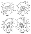
- the mounting flange 130 has a first opening 132 defined by a cylindrical inner surface 134 (Figs. 2 and 3).
- the first opening 132 is centered on the motor axis 120 and is larger in diameter than the motor output shaft 118 to which the second gear 114 is attached.
- a radially extending surface 136 (Fig. 3) connects the first opening 132 to a second opening 138 (Fig. 4) in the mounting flange 130.
- the second opening 138 is defined by a cylindrical inner surface 140 which is not centered on the motor axis 120 but is instead centered on an eccentric axis 142.
- the cylindrical inner surface 140 intersects a radially extending mounting surface 144 of the mounting flange 130 and defines an eccentric depression 146 in the mounting flange.
- the mounting flange 130 further includes a pair of diametrically opposed slots 148.
- the electric motor 60 is a known type for use in an electric steering system.
- the electric motor 60 has a motor housing 146 (Fig. 2) which is generally cylindrical in shape.
- a mounting plate 148 is secured to one end of the motor housing 146.
- the mounting plate 148 has a radially extending mounting surface 150 (Figs. 5 and 6) and a cylindrical inner surface 152 centered on the motor axis 120.
- a bearing assembly 154 is press fit into an opening (not numbered) defined by the cylindrical inner surface 152 and supports the motor output shaft 118 for rotation about the motor axis 120.
- the mounting plate 148 of the electric motor 60 further includes a cylindrical outer surface 160 which projects axially from the mounting surface 150.
- the cylindrical outer surface 160 is centered on the eccentric axis 142 and defines an eccentric projection 162.
- the eccentric projection 162 is slightly smaller in diameter than the eccentric depression 146 in the mounting flange 130.
- the mounting plate 148 further includes a pair of diametrically opposed tapped holes 164.
- the eccentric projection 162 on the mounting surface 150 of the electric motor 60 is received in the eccentric depression 146 in the mounting flange 130 (see Figs. 2 and 7).
- the slots 148 in the mounting flange 130 overlie the tapped holes 164 in the mounting plate 148.
- a screw 170 extends through each of the slots 148 and is received in a respective one of the tapped holes 164 to secure the electric motor 60 to the mounting flange 130.
- the steering assembly 10 further includes an electronic control unit or controller 140 (Fig. 1).
- the controller 140 is preferably secured to the rack housing 30 in a manner not shown.
- the controller 140 is electrically connected to the electric motor 60 by electrical lines 142 and is electrically connected by the electrical lines 19 to the torque sensor 16.
- the controller 140 is operable to receive electrical signals from the torque sensor 16 and to control the electric motor 60 in accordance with the received electrical signals.
- the input shaft 12 rotates about the axis 14.
- the direction and magnitude of the applied steering torque are sensed by the torque sensor 16.
- the torque sensor 16 outputs an electrical signal to the controller 140.
- the electric motor 60 is energized by a control signal transmitted to the electric motor 60 by the controller 140, and the motor output shaft 118 of the electric motor 60 is caused to rotate about the motor axis 120.
- the rotating motor shaft 118 applies a drive force to the second gear 114.
- the second gear 114 which is meshed with teeth on the first gear 112, effects rotation of the first gear and the ball nut 70 about the rack axis 34 at a reduced speed compared to the rotational speed of the motor shaft 118.
- the first and second gears 112 and 114 thus transmit the drive force of the electric motor 60 to the ball nut 70.
- the rotation of the ball nut 70 results in linear movement of the steering member 32.
- the balls 98 transmit the rotation force of the ball nut 70 to the rack portion 40 of the steering member 32. Because the ball nut 70 is fixed in position axially, the steering member 32 is driven to move axially in response, effecting steering movement of the steerable wheels of the vehicle.
- the electric motor 60 thus provides steering assist in response to the applied steering torque.
- the eccentric surfaces 140 and 160 on the gearbox housing 130 and electric motor 60, respectively, provide the steering assembly 10 with a means for adjusting backlash in the gears 112, 114 between the electric motor 60 and the ball nut 70.
- Figs. 7 and 8 show the relative position of the first and second gears 112 and 114 in a first condition where backlash requires adjustment.
- the screws 170 are loosened and the electric motor 60 is manually rotated about the eccentric axis 142 in the direction of arrow A in Fig. 9.
- This manual rotation of the electric motor 60 slides the eccentric surface 160 of the projection 162 along the eccentric surface 140 of the depression 146 in the gearbox housing 130 and causes the motor axis 120 of the electric motor output shaft 118 to shift in the direction of arrow B in Fig. 9. As shown in Fig. 10, this shifting of the transverse axis 120 about which the motor output shaft 118 rotates moves the second gear 114 toward the first gear 112 in the direction of arrow C and into a second condition for the first and second gears 112 and 114 where the backlash has been adjusted.
- the first and second conditions shown in Figs. 7-10 are intended to be of a representative nature only. It should be understood that numerous relative positions of the first and second gears 112 and 114 are possible.
- the present invention thus provides a steering assembly 10 in which the backlash between the gears 112 and 114 is easily manually adjusted. Backlash adjustments can thus be made upon assembly of the steering assembly 10 by the part manufacturer, the vehicle manufacturer, or by a mechanic at a later time as required.
- the present invention provides a steering assembly 10 which is compact in size, relatively inexpensive to produce, and which has high strength and a high gear reduction ratio.
- the invention relates to a steering assembly for turning steerable wheels of a vehicle in response to rotation of a vehicle steering wheel, said steering assembly comprising: a housing; a member which is movable axially within said housing to effect turning movement of the steerable wheels, said member having an externally threaded screw portion; a ball nut disposed in said housing, said ball nut extending around said screw portion of said member and having an internal thread; and a plurality of balls disposed between said internal thread on said ball nut and said externally threaded screw portion of said member for transmitting force between said ball nut and said screw portion to cause axial movement of said member.
Landscapes
- Engineering & Computer Science (AREA)
- Chemical & Material Sciences (AREA)
- Combustion & Propulsion (AREA)
- Transportation (AREA)
- Mechanical Engineering (AREA)
- Power Steering Mechanism (AREA)
- Steering Controls (AREA)
Abstract
Description
- The present invention relates to an electric power steering assembly and, in particular, relates to an electric power steering assembly which includes a ball nut for transmitting force from an electric motor to a steering rack to cause steerable vehicle wheels to turn.
- One known electric power steering apparatus for turning steerable wheels of a vehicle includes a ball nut for transmitting force between an axially movable rack member and an electric motor. Upon actuation of the electric motor, the ball nut is driven to rotate relative to the rack member. The rotational force of the ball nut is transmitted to the rack member by balls to drive the rack member axially. Axial movement of the rack member effects turning movement of the steerable wheels. The advantages of this known steerable wheels. The advantages of this known apparatus include its compact size and high strength.
- In another known electric power steering apparatus, an electric motor is connected with gearing which provides a gear reduction between an electric motor shaft and an output pinion meshed with an axially movable rack member. Rotation of the output pinion by the electric motor causes the rack member to move axially to turn the steerable wheels. The advantages of this known apparatus include a high gear reduction ratio and relatively low cost.
- It is desirable to produce an electric power steering system which is compact in size, relatively inexpensive to produce, and which has high strength and a high gear reduction ratio.
- The present invention is a steering assembly for turning steerable wheels of a vehicle in response to rotation of a vehicle steering wheel. The steering assembly comprises a housing and a member which is movable axially within the housing to effect turning movement of the steerable wheels. The member has an externally threaded screw portion. A ball nut is disposed in the housing. The ball nut extends around the screw portion of the member and has an internal thread. A plurality of balls are disposed between the internal thread on the ball nut and the externally threaded screw portion of the member for transmitting force between the ball nut and the screw portion to cause axial movement of the member. An electric motor provides a drive force to move the member in response to rotation of the steering wheel. The electric motor includes a rotatable output shaft which is rotatable about a motor axis which extends transverse to the meter. Gearing transmits the drive force of the electric motor to the ball nut. The gearing provides a first gear reduction between the output shaft of the electric motor and the ball nut.
- An input shaft is connected between the pinion and the vehicle steering wheel and a torque sensor is operatively coupled with the input shaft. The torque sensor is operable to sense rotation and steering torque applied to the input shaft and to provide a corresponding electrical signal. A controller is electrically connected to the torque sensor and to the electric motor. The controller is operable to receive electrical signals from the torque sensor and to control the electric motor in accordance with the electrical signals.
- The foregoing and other features of the present invention will become apparent to those skilled in the art to which the present invention relates upon reading the following description with reference to the accompanying drawings, wherein:
- Fig. 1 is a schematic view, partially in section, of an electric power steering assembly constructed in accordance with the present invention;
- Fig. 2 is an enlarged view of a portion of Fig. 1;
- Fig. 3 is a view taken along line 3-3 in Fig. 2 with parts omitted for clarity;
- Fig. 4 is a perspective view of the parts shown in Fig. 3;
- Fig. 5 is a view taken along line 5-5 in Fig. 2;
- Fig. 6 is a perspective view of Fig. 5;
- Fig. 7 is a view taken along line 7-7 in Fig. 2 showing parts of the steering assembly in a first position;
- Fig. 8 is a view taken along line 8-8 in Fig. 2 further illustrating the parts of the steering assembly in the first position;
- Fig. 9 is a view similar to Fig. 7 showing the parts of the steering assembly in a second position; and
- Fig. 10 is a view similar to Fig. 8 further illustrating the parts of the steering assembly in the second position.
-
- The present invention relates to an electric power steering assembly and, in particular, relates to an electric power steering assembly which includes a ball nut for transmitting force from an electric motor to a steering rack and an electric motor to cause steerable vehicle wheels to turn. As representative of the present invention, Fig. 1 illustrates an electric
power steering assembly 10 for a vehicle, such as an automobile. - The
steering assembly 10 includes avehicle steering wheel 11 and arotatable input shaft 12 which is operatively coupled, in a manner not shown, for rotation with the steering wheel about a steering axis 14. Atorque sensor 16 is located inside apinion housing 18 and encircles theinput shaft 12. Thetorque sensor 16 includes coils (not shown) which respond to rotation of theinput shaft 12 and output an electrical signal overelectrical lines 19 indicative of the direction and magnitude of the applied steering torque. - A
torsion bar 20 connects theinput shaft 12 to apinion 22 inside thepinion housing 18. The torsion bar 20 twists in response to steering torque applied to the steering wheel. When the torsion bar 20 twists, relative rotation occurs between theinput shaft 12 and thepinion 22. - The
pinion housing 18 is attached to arack housing 30. A linearlymovable steering member 32 extends axially through therack housing 30. Thesteering member 32 is linearly (or axially) movable along arack axis 34. Arack portion 36 of the steering member has a series ofrack teeth 38 which meshingly engage gear teeth (not shown) on thepinion 22. Thesteering member 30 further includes ascrew portion 40 having anexternal thread convolution 41. Thesteering member 32 is connected with steerable wheels (also not shown) of the vehicle throughtie rods 42 located at the distal ends of the steering member. Linear movement of thesteering member 32 along therack axis 34 results in steering movement of the steerable wheels as is known in the art. - The
rack housing 30 has a generally cylindrical configuration including an axially extendingside wall 50 centered on therack axis 34. A radially enlargedsection 52 of therack housing 30 is located at the right end (as viewed in Fig. 1) of therack housing 30. The radially enlargedsection 52 of therack housing 30 defines anannular chamber 54. Anoutboard housing 58 is attached, in a manner not shown, to the radially enlargedsection 52 of therack housing 30 and closes thechamber 54. - The
steering assembly 10 further includes anelectric motor 60, described below in detail, drivably connected to aball nut assembly 70, also described below in detail, for effecting axial movement of thesteering member 32 upon rotation of the steering wheel. In the event of the inability of theelectric motor 60 to effect axial movement of thesteering member 32, the mechanical connection between the gear teeth (not shown) on thepinion 22 and therack teeth 38 on therack portion 36 of thesteering member 32 permits manual steering of the vehicle. - The
ball nut assembly 70 is located in thechamber 54 in the radially enlargedsection 52 of therack housing 30 and encircles thescrew portion 40 of thesteering member 32. Theball nut assembly 70 includes aball nut 72, a plurality offorce transmitting members 74, a firstbearing assembly 76, a gear member 78, and alock nut 80. The ball nut 72 (Fig. 2) has oppositely disposed first andsecond end portions outer surfaces screw thread convolution 90 is formed on the cylindricalinner surface 86 of theball nut 72. Thefirst end portion 82 of theball nut 72 projects axially toward theside wall 50 of therack housing 30 and is supported by asecond bearing assembly 92, shown schematically in the figures. Preferably, thesecond bearing assembly 92 is a needle bearing, but could instead be a ball baring or a journal bearing. Thegear member 72 and thefirst bearing assembly 76 abut one another and are fixedly attached to the cylindricalouter surface 88 of theball nut 72 in acentral portion 94 of the ball nut. Thelock nut 80 screws ontothreads 96 formed in the cylindricalouter surface 88 in the second-end portion 84 of theball nut 72 to axially secure the parts of theball nut assembly 70. - The plurality of force-transmitting
members 74 comprise balls 98 disposed between the internalscrew thread convolution 90 of theball nut 72 and theexternal thread convolution 41 on thescrew portion 40 of the steeringmember 32. The balls 98 are loaded into theball nut assembly 70 in a known manner. Theball nut assembly 70 includes a recirculation passage (not shown) for recirculating the balls 98 upon axial movement of the steeringmember 32 relative to theball nut assembly 70. In accordance with a preferred embodiment of the invention, theball nut assembly 70 provides a gear reduction ratio between theball nut 72 and the steeringmember 32 of between 5:1 and 10:1, and is preferably approximately 6.5:1. - The
electric motor 60 is adjustably mounted to a radially extendinggearbox portion 110 of therack housing 30. Thegearbox portion 110 extends from the radially enlargedsection 52 of therack housing 30. Thegearbox portion 110 contains meshed first andsecond gears first gear 112 is the gear member 78 of theball nut assembly 70. Thefirst gear 112 rotates with theball nut assembly 70 about therack axis 34. Thesecond gear 114 is connected for rotation with amotor output shaft 118 extending from theelectric motor 60. Thesecond gear 114 and themotor output shaft 118 rotate about amotor axis 120. The meshed first andsecond gears motor output shaft 118 of theelectric motor 60 and theball nut assembly 70 of between 2:1 and 5:1, and is preferably approximately 3:1. When the gear reduction ratio of theball nut assembly 70 is combined with the gear reduction ratio of thegears steering assembly 10 is preferably achieved. - In accordance with a preferred embodiment of the invention, the
motor axis 120 extends transverse to the steeringmember 32 at a right angle. It is contemplated, however, that themotor axis 120 could lie parallel to the steeringmember 32 or at a different angle, such as 45°, relative to the steering member. - In further accordance with the preferred embodiment of the invention, the first and
second gears second gears first gear 112 is preferably made of a plastic material and thesecond gear 114 is preferably made of metal so that, when meshed, the gears produce a relatively low level of noise. - The
gearbox portion 110 of therack housing 30 includes a mountingflange 130 oriented perpendicular to themotor axis 120. The mountingflange 130 has afirst opening 132 defined by a cylindrical inner surface 134 (Figs. 2 and 3). Thefirst opening 132 is centered on themotor axis 120 and is larger in diameter than themotor output shaft 118 to which thesecond gear 114 is attached. A radially extending surface 136 (Fig. 3) connects thefirst opening 132 to a second opening 138 (Fig. 4) in the mountingflange 130. Thesecond opening 138 is defined by a cylindricalinner surface 140 which is not centered on themotor axis 120 but is instead centered on aneccentric axis 142. The cylindricalinner surface 140 intersects a radially extending mountingsurface 144 of the mountingflange 130 and defines aneccentric depression 146 in the mounting flange. The mountingflange 130 further includes a pair of diametricallyopposed slots 148. - The
electric motor 60 is a known type for use in an electric steering system. Theelectric motor 60 has a motor housing 146 (Fig. 2) which is generally cylindrical in shape. A mountingplate 148 is secured to one end of themotor housing 146. The mountingplate 148 has a radially extending mounting surface 150 (Figs. 5 and 6) and a cylindricalinner surface 152 centered on themotor axis 120. A bearingassembly 154 is press fit into an opening (not numbered) defined by the cylindricalinner surface 152 and supports themotor output shaft 118 for rotation about themotor axis 120. - The mounting
plate 148 of theelectric motor 60 further includes a cylindricalouter surface 160 which projects axially from the mountingsurface 150. The cylindricalouter surface 160 is centered on theeccentric axis 142 and defines aneccentric projection 162. Theeccentric projection 162 is slightly smaller in diameter than theeccentric depression 146 in the mountingflange 130. The mountingplate 148 further includes a pair of diametrically opposed tappedholes 164. - The
eccentric projection 162 on the mountingsurface 150 of theelectric motor 60 is received in theeccentric depression 146 in the mounting flange 130 (see Figs. 2 and 7). Theradially extending surfaces flange 130 and the mountingplate 148, respectively, abut one another. Theslots 148 in the mountingflange 130 overlie the tappedholes 164 in the mountingplate 148. Ascrew 170 extends through each of theslots 148 and is received in a respective one of the tappedholes 164 to secure theelectric motor 60 to the mountingflange 130. - The steering
assembly 10 further includes an electronic control unit or controller 140 (Fig. 1). Thecontroller 140 is preferably secured to therack housing 30 in a manner not shown. Thecontroller 140 is electrically connected to theelectric motor 60 byelectrical lines 142 and is electrically connected by theelectrical lines 19 to thetorque sensor 16. Thecontroller 140 is operable to receive electrical signals from thetorque sensor 16 and to control theelectric motor 60 in accordance with the received electrical signals. - When steering torque is applied to the vehicle steering wheel, the
input shaft 12 rotates about the axis 14. The direction and magnitude of the applied steering torque are sensed by thetorque sensor 16. Thetorque sensor 16 outputs an electrical signal to thecontroller 140. Theelectric motor 60 is energized by a control signal transmitted to theelectric motor 60 by thecontroller 140, and themotor output shaft 118 of theelectric motor 60 is caused to rotate about themotor axis 120. - The
rotating motor shaft 118 applies a drive force to thesecond gear 114. Thesecond gear 114, which is meshed with teeth on thefirst gear 112, effects rotation of the first gear and theball nut 70 about therack axis 34 at a reduced speed compared to the rotational speed of themotor shaft 118. The first andsecond gears electric motor 60 to theball nut 70. - The rotation of the
ball nut 70 results in linear movement of the steeringmember 32. The balls 98 transmit the rotation force of theball nut 70 to therack portion 40 of the steeringmember 32. Because theball nut 70 is fixed in position axially, the steeringmember 32 is driven to move axially in response, effecting steering movement of the steerable wheels of the vehicle. Theelectric motor 60 thus provides steering assist in response to the applied steering torque. - The
eccentric surfaces gearbox housing 130 andelectric motor 60, respectively, provide thesteering assembly 10 with a means for adjusting backlash in thegears electric motor 60 and theball nut 70. Figs. 7 and 8 show the relative position of the first andsecond gears screws 170 are loosened and theelectric motor 60 is manually rotated about theeccentric axis 142 in the direction of arrow A in Fig. 9. This manual rotation of theelectric motor 60 slides theeccentric surface 160 of theprojection 162 along theeccentric surface 140 of thedepression 146 in thegearbox housing 130 and causes themotor axis 120 of the electricmotor output shaft 118 to shift in the direction of arrow B in Fig. 9. As shown in Fig. 10, this shifting of thetransverse axis 120 about which themotor output shaft 118 rotates moves thesecond gear 114 toward thefirst gear 112 in the direction of arrow C and into a second condition for the first andsecond gears second gears - The present invention thus provides a
steering assembly 10 in which the backlash between thegears steering assembly 10 by the part manufacturer, the vehicle manufacturer, or by a mechanic at a later time as required. - Further, the present invention provides a
steering assembly 10 which is compact in size, relatively inexpensive to produce, and which has high strength and a high gear reduction ratio. - From the above description of the invention, those skilled in the art will perceive improvements, changes and modifications. Such improvements, changes and modifications within the skill of the art are intended to be covered by the appended claims.
- According to its broadest aspect the invention relates to a steering assembly for turning steerable wheels of a vehicle in response to rotation of a vehicle steering wheel, said steering assembly comprising: a housing; a member which is movable axially within said housing to effect turning movement of the steerable wheels, said member having an externally threaded screw portion; a ball nut disposed in said housing, said ball nut extending around said screw portion of said member and having an internal thread; and a plurality of balls disposed between said internal thread on said ball nut and said externally threaded screw portion of said member for transmitting force between said ball nut and said screw portion to cause axial movement of said member.
- It should be noted that the objects and advantages of the invention may be attained by means of any compatible combination(s) particularly pointed out in the items of the following summary of the invention and the appended claims.
-
- 1. A steering assembly for turning steerable
wheels of a vehicle in response to rotation of a
vehicle steering wheel, said steering assembly
comprising:
- a housing;
- a member which is movable axially within said housing to effect turning movement of the steerable wheels, said member having an externally threaded screw portion;
- a ball nut disposed in said housing, said ball nut extending around said screw portion of said member and having an internal thread;
- a plurality of balls disposed between said internal thread on said ball nut and said externally threaded screw portion of said member for transmitting force between said ball nut and said screw portion to cause axial movement of said member;
- an electric motor for providing a drive force to move said member in response to rotation of the steering wheel, said electric motor including a rotatable output shaft which is rotatable about a motor axis which extends transverse to said member; and
- gearing for transmitting the drive force of said electric motor to said ball nut, said gearing providing a first gear reduction between said output shaft of said electric motor and said ball nut.
- 2. The steering assembly further comprising a pinion connected with the vehicle steering wheel, said member having a rack portion for engagement with said pinion.
- 3. The steering assembly further comprising an input shaft connected between said pinion and the vehicle steering wheel and a torque sensor associated with said input shaft, said torque sensor being operable to sense rotation and steering torque applied to said input shaft and to provide a corresponding electrical signal.
- 4. The steering assembly further comprising a controller electrically connected to said torque sensor and to said electric motor, said controller being operable to receive electrical signals from said torque sensor and to control said electric motor in accordance with the electrical signals.
- 5. The steering assembly wherein said gearing comprises first and second gears, said first gear being fixed for rotation with said ball nut about a first axis, said second gear being fixed for rotation with said output shaft of said electric motor about said motor axis.
- 6. The steering assembly wherein said first and second gears are contained within said housing, said electric motor being adjustably mounted to said housing.
- 7. The steering assembly further comprising adjusting means for adjusting backlash between said first and second gears, said adjusting means including eccentric surface means for shifting said motor axis of said electric motor and said second gear relative to said first gear.
- 8. The steering assembly wherein said eccentric surface means includes an annular projection extending axially from a first end of said electric motor.
- 9. The steering assembly wherein said annular projection has a cylindrical outer surface comprising a first eccentric surface which is centered in an eccentric axis, said eccentric axis extending parallel to and radially offset from said motor axis.
- 10. The steering assembly wherein said housing includes a second eccentric surface defining an opening for receiving said annular projection.
- 11. The steering assembly wherein said first gear is made of a plastic material.
- 12. The steering assembly wherein said second gear is made of metal.
- 13. The steering assembly wherein said first gear reduction between said output shaft of said electric motor and said ball nut has a ratio of at least 3:1.
- 14. The steering assembly wherein said ball nut provides a second gear reduction between said ball nut and said member, said second gear reduction having a ratio of at least 6:1.
- 15. The steering assembly wherein said first and second gear reductions provide an overall gear reduction between said electric motor and said member having a ratio of at least 18:1.
- 16. The steering assembly further including at least one bearing assembly disposed between said housing and said ball nut for supporting rotation of said ball nut.
- 17. The steering assembly wherein said first gear is located axially between first and second bearing assemblies.
- 18. A steering assembly for turning steerable
wheels of a vehicle in response to rotation of a
vehicle steering wheel, said steering assembly
comprising:
- a housing;
- a member which is movable axially within said housing to effect turning movement of the steerable wheels, said member having an externally threaded screw portion;
- a ball nut disposed in said housing and extending around said screw portion of said member, said ball nut having an outer surface and an internal surface which is threaded,
- said ball nut including a first gear fixed to said outer surface for causing rotation of said ball nut about a first axis;
- a plurality of balls disposed between said threaded internal surface of said ball nut and said externally threaded screw portion of said member for transmitting force between said ball nut and said screw portion to cause axial movement of said member;
- an electric motor for providing a drive force to move said member in response to rotation of the steering wheel, said electric motor including a rotatable output shaft which is rotatable about a motor axis which extends traverse to said member; and
- a second gear meshed with said first gear for transmitting the drive force of said electric motor to said first gear on said ball nut, said second gear being fixed for rotation with said output shaft about said motor axis, said first and second gears providing a first gear reduction between said electric motor and said ball nut.
- 19. The steering assembly further comprising a pinion connected with the vehicle steering wheel, said member including a rack portion for engagement with said pinion.
- 20. The steering assembly further comprising an input shaft connected between said pinion and the vehicle steering wheel and a torque sensor associated with said input shaft, said torque sensor being operable to sense rotation and steering torque applied to said input shaft and to provide a corresponding electrical signal.
- 21. The steering assembly further comprising a controller electrically connected to said torque sensor and to said electric motor, said controller being operable to receive electrical signals from said torque sensor and to control said electric motor in accordance with the electrical signals.
- 22. The steering assembly wherein said first and second gears are contained within said housing, said electric motor being adjustably mounted to said housing.
- 23. The steering assembly further comprising adjusting means for adjusting backlash between said first and second gears, said adjusting means including eccentric surface means for shifting said motor axis of said electric motor and said second gear relative to said first gear.
- 24. The steering assembly wherein said eccentric surface means includes an annular projection extending axially from a first end of said electric motor.
- 25. The steering assembly wherein said annular projection has a cylindrical outer surface comprising a first eccentric surface which is centered in an eccentric axis, said eccentric axis extending parallel to and radially-offset from said motor axis.
- 26. The steering assembly wherein said housing includes a second eccentric surface defining an opening for receiving said annular projection.
- 27. The steering assembly wherein said first gear reduction between said output shaft of said electric motor and said ball nut has a ratio of at least 3:1.
- 28. The steering assembly wherein said ball nut provides a second gear reduction between said ball nut and said member, said second gear reduction having a ratio of at least 6:1.
- 29. The steering assembly wherein said first and second gear reductions provide an overall gear reduction between said electric motor and said member having a ratio of at least 18:1.
-
Claims (10)
- A steering assembly for turning steerable wheels of a vehicle in response to rotation of a vehicle steering wheel, said steering assembly comprising:a housing;a member which is movable axially within said housing to effect turning movement of the steerable wheels, said member having an externally threaded screw portion;a ball nut disposed in said housing, said ball nut extending around said screw portion of said member and having an internal thread;a plurality of balls disposed between said internal thread on said ball nut and said externally threaded screw portion of said member for transmitting force between said ball nut and said screw portion to cause axial movement of said member;an electric motor for providing a drive force to move said member in response to rotation of the steering wheel, said electric motor including a rotatable output shaft which is rotatable about a motor axis which extends transverse to said member; andgearing for transmitting the drive force of said electric motor to said ball nut, said gearing providing a first gear reduction between said output shaft of said electric motor and said ball nut.
- The steering assembly of claim 1 further comprising a pinion connected with the vehicle steering wheel, said member having a rack portion for engagement with said pinion.
- The steering assembly of claim 2 further comprising an input shaft connected between said pinion and the vehicle steering wheel and a torque sensor associated with said input shaft, said torque sensor being operable to sense rotation and steering torque applied to said input shaft and to provide a corresponding electrical signal.
- The steering assembly of claim 3 further comprising a controller electrically connected to said torque sensor and to said electric motor, said controller being operable to receive electrical signals from said torque sensor and to control said electric motor in accordance with the electrical signals.
- The steering assembly of any of the preceding claims wherein said gearing comprises first and second gears, said first gear being fixed for rotation with said ball nut about a first axis, said second gear being fixed for rotation with said output shaft of said electric motor about said motor axis,and/or wherein preferably said first and second gears are contained within said housing, said electric motor being adjustably mounted to said housing,and/or further preferably comprising adjusting means for adjusting backlash between said first and second gears, said adjusting means including eccentric surface means for shifting said motor axis of said electric motor and said second gear relative to said first gear,and/or wherein preferably said eccentric surface means includes an annular projection extending axially from a- first end of said electric motor,and/or wherein preferably said annular projection has a cylindrical outer surface comprising a first eccentric surface which is centered in an eccentric axis, said eccentric axis extending parallel to and radially offset from said motor axis,and/or wherein preferably said housing includes a second eccentric surface defining an opening for receiving said annular projection,and/or wherein preferably said first gear is made of a plastic material,and/or wherein preferably said second gear is made of metal.
- The steering assembly of any of the preceding claims wherein said first gear reduction between said output shaft of said electric motor and said ball nut has a ration of at least 3:1,and/or wherein preferably said ball nut provides a second gear reduction between said ball nut and said member, said second gear reduction having a ratio of at least 6:1,and/or wherein preferably said first and second gear reductions provide an overall gear reduction between said electric motor and said member having a ratio of at least 18:1,and/or further preferably including at least one bearing assembly disposed between said housing and said ball nut for supporting rotation of said ball nut,and/or wherein preferably said first gear is located axially between first and second bearing assemblies.
- A steering assembly for turning steerable wheels of a vehicle in response to rotation of a vehicle steering wheel, said steering assembly comprising:a housing;a member which is movable axially within said housing to effect turning movement of the steerable wheels, said member having an externally threaded screw portion;a ball nut disposed in said housing and extending around said screw portion of said member, said ball nut having an outer surface and an internal surface which is threaded,said ball nut including a first gear fixed to said outer surface for causing rotation of said ball nut about a first axis;a plurality of balls disposed between said threaded internal surface of said ball nut and said externally threaded screw portion of said member for transmitting force between said ball nut and said screw portion to cause axial movement of said member;an electric motor for providing a drive force to move said member in response to rotation of the steering wheel, said electric motor including a rotatable output shaft which is rotatable about a motor axis which extends traverse to said member; anda second gear meshed with said first gear for transmitting the drive force of said electric motor to said first gear on said-ball nut, said second gear being fixed for rotation with said output shaft about said motor axis, said first and second gears providing a first gear reduction between said electric motor and said ball nut.
- The steering assembly of any of the preceding claims further comprising a pinion connected with the vehicle steering wheel, said member including a rack portion for engagement with said pinion,and/or further preferably comprising an input shaft connected between said pinion and the vehicle steering wheel and a torque sensor associated with said input shaft, said torque sensor being operable to sense rotation and steering torque applied to said input shaft and to provide a corresponding electrical signal,and/or further preferably comprising a controller electrically connected to said torque sensor and to said electric motor, said controller being operable to receive electrical signals from said torque sensor and to control said electric motor in accordance with the electrical signals.
- The steering assembly of any of the preceding claims wherein said first and second gears are contained within said housing, said electric motor being adjustably mounted to said housing,and/or further preferably comprising adjusting means for adjusting backlash between said first and second gears, said adjusting means including eccentric surface means for shifting said motor axis of said electric motor and said second gear relative to said first gear,and/or wherein preferably said eccentric surface means includes an annular projection extending axially from a first end of said electric motor,and/or wherein preferably said annular projection has a cylindrical outer surface comprising a first eccentric surface which is centered in an eccentric axis, said eccentric axis extending parallel to and radially-offset from said motor axis.and/or wherein preferably said housing includes a second eccentric surface defining an opening for receiving said annular projection,and/or wherein preferably said first gear reduction between said output shaft of said electric motor and said ball nut has a ratio of at least 3:1,and/or wherein preferably said ball nut provides a second gear reduction between said ball nut and said member, said second gear reduction having a ratio of at least 6:1,and/or wherein preferably said first and second gear reductions provide an overall gear reduction between said electric motor and said member having a ratio of at least 18:1.
- A steering assembly for turning steerable wheels of a vehicle in response to rotation of a vehicle steering wheel, said steering assembly comprising:a housing;a member which is movable axially within said housing to effect turning movement of the steerable wheels, said member having an externally threaded screw portion;a ball nut disposed in said housing, said ball nut extending around said screw portion of said member and having an internal thread; anda plurality of balls disposed between said internal thread on said ball nut and said externally threaded screw portion of said member for transmitting force between said ball nut and said screw portion to cause axial movement of said member.
Applications Claiming Priority (2)
| Application Number | Priority Date | Filing Date | Title |
|---|---|---|---|
| US09/221,046 US6155376A (en) | 1998-12-28 | 1998-12-28 | Electric power steering assembly |
| US221046 | 1998-12-28 |
Publications (3)
| Publication Number | Publication Date |
|---|---|
| EP1016581A2 true EP1016581A2 (en) | 2000-07-05 |
| EP1016581A3 EP1016581A3 (en) | 2005-10-05 |
| EP1016581B1 EP1016581B1 (en) | 2009-07-29 |
Family
ID=22826119
Family Applications (1)
| Application Number | Title | Priority Date | Filing Date |
|---|---|---|---|
| EP99124046A Expired - Lifetime EP1016581B1 (en) | 1998-12-28 | 1999-12-09 | Electric power steering assembly |
Country Status (5)
| Country | Link |
|---|---|
| US (1) | US6155376A (en) |
| EP (1) | EP1016581B1 (en) |
| JP (1) | JP3245582B2 (en) |
| BR (1) | BR9904353A (en) |
| DE (1) | DE69941177D1 (en) |
Cited By (13)
| Publication number | Priority date | Publication date | Assignee | Title |
|---|---|---|---|---|
| DE10032120A1 (en) * | 1999-12-17 | 2001-07-19 | Zf Lenksysteme Gmbh | Steering device for motor vehicles |
| EP1225117A1 (en) * | 2001-01-22 | 2002-07-24 | Koyo Seiko Co., Ltd. | An electric power steering system |
| NL1017392C2 (en) * | 2001-02-19 | 2002-08-20 | Skf Ab | Steering actuator device for motor vehicle with electric motor connected to screw device, includes reserve electric motor |
| WO2003006301A1 (en) * | 2001-07-10 | 2003-01-23 | Toyoda Koki Kabushiki Kaisha | Electronic control power steering device |
| EP1279860A2 (en) * | 2001-07-27 | 2003-01-29 | Robert Bosch Gmbh | Actuator gearing |
| EP1254826A3 (en) * | 2001-04-13 | 2004-10-27 | Nsk Ltd | Electric power steering apparatus |
| US6810985B1 (en) | 1999-12-17 | 2004-11-02 | Zf Lenksysteme Gmbh | Steering device for a vehicle |
| FR2855485A1 (en) * | 2003-05-28 | 2004-12-03 | Koyo Seiko Co | ELECTRIC POWER STEERING DEVICE |
| FR2862038A1 (en) * | 2003-11-06 | 2005-05-13 | Koyo Steering Europe Kse | Steering system for motor vehicle, has steering bar including screw, locked in rotation, contacting with screw nut, locked in axial translation, where screw nut is rotatably mounted and coupled with steering column |
| EP1640243A1 (en) * | 2004-09-23 | 2006-03-29 | Mando Corporation | Rack type electric power steering apparatus |
| EP1666335A1 (en) * | 2003-08-29 | 2006-06-07 | Favess Co., Ltd. | Electronic control power steering device |
| CN108016492A (en) * | 2016-10-31 | 2018-05-11 | 株式会社捷太格特 | Transfer |
| EP3441643A1 (en) * | 2017-08-08 | 2019-02-13 | Kabushiki Kaisha Yaskawa Denki | Speed reducer and actuator |
Families Citing this family (40)
| Publication number | Priority date | Publication date | Assignee | Title |
|---|---|---|---|---|
| US7007718B2 (en) * | 1997-11-24 | 2006-03-07 | Dayco Products, Llc | Energy attenuation apparatus for a conduit conveying liquid under pressure, system incorporating same, and method of attenuating energy in a conduit |
| JP2000177607A (en) * | 1998-12-14 | 2000-06-27 | Toyoda Mach Works Ltd | Motor driven power steering device |
| US6749040B1 (en) * | 1999-09-01 | 2004-06-15 | Delphi Technologies, Inc. | Electric power assisted rack and pinion system |
| US6422334B1 (en) * | 1999-09-17 | 2002-07-23 | Delphi Technologies, Inc. | Ball screw rack assembly |
| US6543569B1 (en) * | 1999-10-08 | 2003-04-08 | Honda Giken Kogyo Kabushiki Kaisha | Electric power steering apparatus |
| JP2001275325A (en) * | 2000-03-27 | 2001-10-05 | Honda Motor Co Ltd | Motor-driven power steering device |
| DE10025501C2 (en) * | 2000-05-23 | 2002-05-02 | Bosch Gmbh Robert | Control arrangement for an adjustable housing |
| GB2370023B (en) * | 2000-07-21 | 2004-03-10 | Nsk Ltd | Electrically driven power steering apparatus |
| US6419042B1 (en) * | 2000-10-03 | 2002-07-16 | Trw Inc. | Integrated electric power hydraulic steering system |
| JP2003127879A (en) * | 2001-10-22 | 2003-05-08 | Toyoda Mach Works Ltd | Electric power steering device |
| DE10215116C1 (en) * | 2002-04-05 | 2003-07-10 | Siemens Ag | Motor vehicle automatic transmission drive position control has stop plate with actuator to rotate it and sensor for angular position |
| US7055646B2 (en) | 2002-04-12 | 2006-06-06 | Trw Inc. | Electric power steering assembly |
| US6644432B1 (en) | 2002-06-27 | 2003-11-11 | Trw Automotive U.S. Llc | Electric power steering assembly |
| US6960145B2 (en) | 2002-08-30 | 2005-11-01 | Trw, Inc. | Belt tensioner for electric power steering unit |
| JP4013132B2 (en) * | 2002-09-30 | 2007-11-28 | 株式会社ジェイテクト | Electric power steering device |
| AU2003300572A1 (en) * | 2002-11-29 | 2004-06-23 | Continental Teves Ag And Co. Ohg | Quiet, vibration-free superimposed transmission for a superimposed steering system |
| DE10258826A1 (en) * | 2002-12-17 | 2004-07-15 | Ina-Schaeffler Kg | Drive device with a Wälzkörpergewindetrieb |
| JP2004314854A (en) * | 2003-04-17 | 2004-11-11 | Koyo Seiko Co Ltd | Steering device for vehicle |
| KR20070020147A (en) * | 2003-05-06 | 2007-02-16 | 닛본 세이고 가부시끼가이샤 | Belt speed reducer for electric power steering device and electric power steering device |
| US7591204B2 (en) | 2003-05-06 | 2009-09-22 | Nsk Ltd. | Belt speed reducing apparatus for electric power steering apparatus and electric power steering apparatus |
| JP2005007969A (en) * | 2003-06-17 | 2005-01-13 | Koyo Seiko Co Ltd | Power steering apparatus |
| US7185515B2 (en) * | 2003-06-27 | 2007-03-06 | Owens-Brockway Glass Container Inc. | Invert arm assembly for glassware forming machine |
| JP4411952B2 (en) * | 2003-12-04 | 2010-02-10 | 株式会社ジェイテクト | Vehicle steering system |
| JP2007531489A (en) * | 2004-03-31 | 2007-11-01 | ダナハー モーション ストックホルム アクチボラゲット | Electric actuator |
| DE102005015451A1 (en) * | 2005-04-04 | 2006-10-05 | Thyssenkrupp Presta Ag | Steering system e.g. servo-steering mechanism, has motor, which along with sub housing is adjusted at its rotational axis in radial direction, and worm shaft is supported at its ends in bearing and differential coupling |
| US20060278466A1 (en) * | 2005-06-13 | 2006-12-14 | Bo Cheng | Electric power steering systems |
| JPWO2007026801A1 (en) * | 2005-08-31 | 2009-03-26 | Thk株式会社 | Steering device and motion conversion device used therefor |
| JP4808541B2 (en) * | 2006-04-26 | 2011-11-02 | 本田技研工業株式会社 | Electric power steering device |
| US7909132B2 (en) * | 2008-09-19 | 2011-03-22 | Trw Automotive U.S. Llc | Apparatus for use in turning steerable vehicle wheels |
| US20100072738A1 (en) * | 2008-09-19 | 2010-03-25 | Trw Automotive U.S. Llc | Steering System |
| KR20100082225A (en) * | 2009-01-08 | 2010-07-16 | 삼성전자주식회사 | Robot joint driving apparatus and robot having the same |
| DE102009002933A1 (en) * | 2009-05-08 | 2010-11-11 | Zf Friedrichshafen Ag | Steerable vehicle axle for commercial vehicle, has axle arch, where axle head is supported at axle arch ends, and axle heads are steerable over steering link |
| DE102009029538A1 (en) * | 2009-09-17 | 2011-03-31 | Zf Lenksysteme Gmbh | Steering device, in particular electric power steering device for a motor vehicle |
| US8328464B2 (en) | 2011-02-04 | 2012-12-11 | Wacker Neuson Production Americas Llc | Vibratory roller with composite exciter drive gear |
| DE102011084510A1 (en) * | 2011-06-10 | 2012-12-13 | Robert Bosch Gmbh | Steering system in a vehicle |
| JP2014180875A (en) * | 2013-03-18 | 2014-09-29 | Hitachi Automotive Systems Ltd | Electric power steering system |
| US9812923B2 (en) | 2014-05-23 | 2017-11-07 | Aero Industries, Inc. | Gear motor |
| US11855581B2 (en) * | 2017-07-18 | 2023-12-26 | Polar Racking Inc. | Solar panel support and drive system |
| JP6875364B2 (en) * | 2018-12-27 | 2021-05-26 | ファナック株式会社 | Gear mechanism, gear adjustment method and robot |
| US11173949B2 (en) * | 2019-06-21 | 2021-11-16 | Zf Active Safety And Electronics Us Llc | Apparatus for use in turning steerable vehicle wheels |
Family Cites Families (16)
| Publication number | Priority date | Publication date | Assignee | Title |
|---|---|---|---|---|
| US3882949A (en) * | 1972-11-16 | 1975-05-13 | Us Health | Universal wheelchair for the severely disabled |
| US4415054A (en) * | 1982-08-05 | 1983-11-15 | Trw Inc. | Steering gear |
| AU574696B2 (en) * | 1983-07-22 | 1988-07-14 | Nippon Seiko K.K. | Power assist steering gear assembly |
| US4666014A (en) * | 1986-05-08 | 1987-05-19 | Trw Inc. | Floating ball-nut for an electric assist steering system |
| US4694925A (en) * | 1986-05-30 | 1987-09-22 | Trw Inc. | Steering apparatus |
| US4987963A (en) * | 1988-12-27 | 1991-01-29 | Ford Motor Company | Steering gear for the roadwheels of a vehicle |
| JP2952942B2 (en) * | 1990-03-15 | 1999-09-27 | 日本精工株式会社 | Electric power steering device |
| JPH03122978U (en) * | 1990-03-28 | 1991-12-13 | ||
| US5437349A (en) * | 1993-03-08 | 1995-08-01 | Honda Giken Kogyo Kabushiki Kaisha | Electrically operated power steering apparatus |
| DE69416968T2 (en) * | 1993-12-27 | 1999-09-30 | Nsk Ltd | Power steering |
| US5492191A (en) * | 1994-12-14 | 1996-02-20 | General Motors Corporation | Power steering gear for motor vehicle |
| JPH08177984A (en) * | 1994-12-28 | 1996-07-12 | Fanuc Ltd | Gear device constituted to have adjustable back-lash |
| JP3579779B2 (en) * | 1996-01-18 | 2004-10-20 | 光洋精工株式会社 | Electric power steering device |
| US5921344A (en) * | 1997-06-03 | 1999-07-13 | Trw Inc. | Electric steering system |
| US5975234A (en) * | 1997-12-03 | 1999-11-02 | Trw Inc. | Electric steering system with plastic motor tube |
| JP4056172B2 (en) * | 1999-04-01 | 2008-03-05 | 株式会社ショーワ | Electric power steering device |
-
1998
- 1998-12-28 US US09/221,046 patent/US6155376A/en not_active Expired - Lifetime
-
1999
- 1999-09-23 BR BR9904353-0A patent/BR9904353A/en not_active IP Right Cessation
- 1999-10-19 JP JP29612899A patent/JP3245582B2/en not_active Expired - Lifetime
- 1999-12-09 DE DE69941177T patent/DE69941177D1/en not_active Expired - Lifetime
- 1999-12-09 EP EP99124046A patent/EP1016581B1/en not_active Expired - Lifetime
Non-Patent Citations (1)
| Title |
|---|
| None |
Cited By (25)
| Publication number | Priority date | Publication date | Assignee | Title |
|---|---|---|---|---|
| DE10032120A1 (en) * | 1999-12-17 | 2001-07-19 | Zf Lenksysteme Gmbh | Steering device for motor vehicles |
| US6810985B1 (en) | 1999-12-17 | 2004-11-02 | Zf Lenksysteme Gmbh | Steering device for a vehicle |
| EP1384653A3 (en) * | 2001-01-22 | 2004-03-24 | Koyo Seiko Co., Ltd. | An electric power steering system |
| US6629578B2 (en) | 2001-01-22 | 2003-10-07 | Koyo Seiko Co., Ltd. | Electric power steering system |
| EP1384653A2 (en) * | 2001-01-22 | 2004-01-28 | Koyo Seiko Co., Ltd. | An electric power steering system |
| EP1384654A2 (en) * | 2001-01-22 | 2004-01-28 | Koyo Seiko Co., Ltd. | An electric power steering system |
| US6918457B2 (en) | 2001-01-22 | 2005-07-19 | Koyo Seiko Co., Ltd. | Electric power steering system |
| EP1384654A3 (en) * | 2001-01-22 | 2004-03-24 | Koyo Seiko Co., Ltd. | An electric power steering system |
| EP1225117A1 (en) * | 2001-01-22 | 2002-07-24 | Koyo Seiko Co., Ltd. | An electric power steering system |
| US6823962B2 (en) | 2001-01-22 | 2004-11-30 | Koyo Seiko Co., Ltd. | Electric power steering system |
| NL1017392C2 (en) * | 2001-02-19 | 2002-08-20 | Skf Ab | Steering actuator device for motor vehicle with electric motor connected to screw device, includes reserve electric motor |
| US7284634B2 (en) | 2001-04-13 | 2007-10-23 | Nsk, Ltd. | Electric power steering apparatus |
| EP1254826A3 (en) * | 2001-04-13 | 2004-10-27 | Nsk Ltd | Electric power steering apparatus |
| WO2003006301A1 (en) * | 2001-07-10 | 2003-01-23 | Toyoda Koki Kabushiki Kaisha | Electronic control power steering device |
| US6973990B2 (en) | 2001-07-10 | 2005-12-13 | Toyoda Koki Kabushiki Kaisha | Electronic control power steering device |
| EP1279860A3 (en) * | 2001-07-27 | 2004-01-21 | Robert Bosch Gmbh | Actuator gearing |
| EP1279860A2 (en) * | 2001-07-27 | 2003-01-29 | Robert Bosch Gmbh | Actuator gearing |
| FR2855485A1 (en) * | 2003-05-28 | 2004-12-03 | Koyo Seiko Co | ELECTRIC POWER STEERING DEVICE |
| EP1666335A1 (en) * | 2003-08-29 | 2006-06-07 | Favess Co., Ltd. | Electronic control power steering device |
| EP1666335A4 (en) * | 2003-08-29 | 2010-06-16 | Jtekt Corp | Electronic control power steering device |
| FR2862038A1 (en) * | 2003-11-06 | 2005-05-13 | Koyo Steering Europe Kse | Steering system for motor vehicle, has steering bar including screw, locked in rotation, contacting with screw nut, locked in axial translation, where screw nut is rotatably mounted and coupled with steering column |
| EP1640243A1 (en) * | 2004-09-23 | 2006-03-29 | Mando Corporation | Rack type electric power steering apparatus |
| CN108016492A (en) * | 2016-10-31 | 2018-05-11 | 株式会社捷太格特 | Transfer |
| EP3441643A1 (en) * | 2017-08-08 | 2019-02-13 | Kabushiki Kaisha Yaskawa Denki | Speed reducer and actuator |
| US10808803B2 (en) | 2017-08-08 | 2020-10-20 | Kabushiki Kaisha Yaskawa Denki | Speed reducer and actuator |
Also Published As
| Publication number | Publication date |
|---|---|
| DE69941177D1 (en) | 2009-09-10 |
| JP3245582B2 (en) | 2002-01-15 |
| EP1016581B1 (en) | 2009-07-29 |
| US6155376A (en) | 2000-12-05 |
| EP1016581A3 (en) | 2005-10-05 |
| BR9904353A (en) | 2000-09-12 |
| JP2000190855A (en) | 2000-07-11 |
Similar Documents
| Publication | Publication Date | Title |
|---|---|---|
| US6155376A (en) | Electric power steering assembly | |
| EP1006040B1 (en) | Electric power steering apparatus | |
| US6360841B1 (en) | Power steering mechanism with magnetoelastic torsion bar | |
| US6000491A (en) | Electric power steering apparatus having steering torque sensor integrally assembled in steering device with variable steering ratio | |
| KR0139705B1 (en) | Electric power steering apparatus | |
| US6644432B1 (en) | Electric power steering assembly | |
| US7669691B2 (en) | Steering device for vehicle | |
| US5921344A (en) | Electric steering system | |
| US20030192734A1 (en) | Electric power steering assembly | |
| JPS62261573A (en) | Wheel steering gear | |
| US20210188342A1 (en) | Steering column and steer-by-wire steering system | |
| CN111615482B (en) | Device for steering steerable vehicle wheels | |
| EP0279034A1 (en) | Center take-off electric rack and pinion steering gear | |
| JP3779743B2 (en) | Electric power steering device | |
| EP3621868A1 (en) | Apparatus for use in turning steerable vehicle wheels | |
| US7604085B2 (en) | Electric power steering apparatus | |
| JP2005324708A (en) | Electric power steering device | |
| US20230142494A1 (en) | Apparatus for use in turning steerable vehicle wheels | |
| JP3613696B2 (en) | Electric power steering device | |
| JP2589067Y2 (en) | Power steering device | |
| JPS61139560A (en) | Electrical power steering device | |
| EP0967133A2 (en) | Electronic control unit mounting arrangement for electric power steering system | |
| JPH0644674U (en) | Electric steering angle imparting device | |
| JP3713346B2 (en) | Electric power steering device | |
| JPH045168A (en) | Motor-driven power steering |
Legal Events
| Date | Code | Title | Description |
|---|---|---|---|
| PUAI | Public reference made under article 153(3) epc to a published international application that has entered the european phase |
Free format text: ORIGINAL CODE: 0009012 |
|
| AK | Designated contracting states |
Kind code of ref document: A2 Designated state(s): AT BE CH CY DE DK ES FI FR GB GR IE IT LI LU MC NL PT SE |
|
| AX | Request for extension of the european patent |
Free format text: AL;LT;LV;MK;RO;SI |
|
| RAP1 | Party data changed (applicant data changed or rights of an application transferred) |
Owner name: TRW AUTOMOTIVE U.S. LLC |
|
| PUAL | Search report despatched |
Free format text: ORIGINAL CODE: 0009013 |
|
| AK | Designated contracting states |
Kind code of ref document: A3 Designated state(s): AT BE CH CY DE DK ES FI FR GB GR IE IT LI LU MC NL PT SE |
|
| AX | Request for extension of the european patent |
Extension state: AL LT LV MK RO SI |
|
| 17P | Request for examination filed |
Effective date: 20060329 |
|
| AKX | Designation fees paid |
Designated state(s): DE FR GB IT |
|
| 17Q | First examination report despatched |
Effective date: 20060518 |
|
| GRAP | Despatch of communication of intention to grant a patent |
Free format text: ORIGINAL CODE: EPIDOSNIGR1 |
|
| RAP1 | Party data changed (applicant data changed or rights of an application transferred) |
Owner name: TRW AUTOMOTIVE U.S. LLC |
|
| GRAS | Grant fee paid |
Free format text: ORIGINAL CODE: EPIDOSNIGR3 |
|
| GRAA | (expected) grant |
Free format text: ORIGINAL CODE: 0009210 |
|
| AK | Designated contracting states |
Kind code of ref document: B1 Designated state(s): DE FR GB IT |
|
| REG | Reference to a national code |
Ref country code: GB Ref legal event code: FG4D |
|
| REF | Corresponds to: |
Ref document number: 69941177 Country of ref document: DE Date of ref document: 20090910 Kind code of ref document: P |
|
| PLBE | No opposition filed within time limit |
Free format text: ORIGINAL CODE: 0009261 |
|
| STAA | Information on the status of an ep patent application or granted ep patent |
Free format text: STATUS: NO OPPOSITION FILED WITHIN TIME LIMIT |
|
| 26N | No opposition filed |
Effective date: 20100503 |
|
| GBPC | Gb: european patent ceased through non-payment of renewal fee |
Effective date: 20091209 |
|
| REG | Reference to a national code |
Ref country code: FR Ref legal event code: ST Effective date: 20100831 |
|
| PG25 | Lapsed in a contracting state [announced via postgrant information from national office to epo] |
Ref country code: FR Free format text: LAPSE BECAUSE OF NON-PAYMENT OF DUE FEES Effective date: 20091231 |
|
| PG25 | Lapsed in a contracting state [announced via postgrant information from national office to epo] |
Ref country code: GB Free format text: LAPSE BECAUSE OF NON-PAYMENT OF DUE FEES Effective date: 20091209 |
|
| PG25 | Lapsed in a contracting state [announced via postgrant information from national office to epo] |
Ref country code: IT Free format text: LAPSE BECAUSE OF FAILURE TO SUBMIT A TRANSLATION OF THE DESCRIPTION OR TO PAY THE FEE WITHIN THE PRESCRIBED TIME-LIMIT Effective date: 20090729 |
|
| PGFP | Annual fee paid to national office [announced via postgrant information from national office to epo] |
Ref country code: DE Payment date: 20181231 Year of fee payment: 20 |
|
| REG | Reference to a national code |
Ref country code: DE Ref legal event code: R071 Ref document number: 69941177 Country of ref document: DE |