EP1014744A2 - Communication system architecture, apparatus and management and signalling method therein - Google Patents
Communication system architecture, apparatus and management and signalling method therein Download PDFInfo
- Publication number
- EP1014744A2 EP1014744A2 EP99307965A EP99307965A EP1014744A2 EP 1014744 A2 EP1014744 A2 EP 1014744A2 EP 99307965 A EP99307965 A EP 99307965A EP 99307965 A EP99307965 A EP 99307965A EP 1014744 A2 EP1014744 A2 EP 1014744A2
- Authority
- EP
- European Patent Office
- Prior art keywords
- msh
- element manager
- communication system
- oss
- intermediate element
- Prior art date
- Legal status (The legal status is an assumption and is not a legal conclusion. Google has not performed a legal analysis and makes no representation as to the accuracy of the status listed.)
- Withdrawn
Links
Images

Classifications
-
- H—ELECTRICITY
- H04—ELECTRIC COMMUNICATION TECHNIQUE
- H04L—TRANSMISSION OF DIGITAL INFORMATION, e.g. TELEGRAPHIC COMMUNICATION
- H04L41/00—Arrangements for maintenance, administration or management of data switching networks, e.g. of packet switching networks
- H04L41/04—Network management architectures or arrangements
- H04L41/044—Network management architectures or arrangements comprising hierarchical management structures
-
- H—ELECTRICITY
- H04—ELECTRIC COMMUNICATION TECHNIQUE
- H04L—TRANSMISSION OF DIGITAL INFORMATION, e.g. TELEGRAPHIC COMMUNICATION
- H04L41/00—Arrangements for maintenance, administration or management of data switching networks, e.g. of packet switching networks
- H04L41/02—Standardisation; Integration
- H04L41/0226—Mapping or translating multiple network management protocols
-
- H—ELECTRICITY
- H04—ELECTRIC COMMUNICATION TECHNIQUE
- H04Q—SELECTING
- H04Q11/00—Selecting arrangements for multiplex systems
- H04Q11/04—Selecting arrangements for multiplex systems for time-division multiplexing
- H04Q11/0428—Integrated services digital network, i.e. systems for transmission of different types of digitised signals, e.g. speech, data, telecentral, television signals
- H04Q11/0478—Provisions for broadband connections
-
- H—ELECTRICITY
- H04—ELECTRIC COMMUNICATION TECHNIQUE
- H04Q—SELECTING
- H04Q3/00—Selecting arrangements
- H04Q3/0016—Arrangements providing connection between exchanges
- H04Q3/0025—Provisions for signalling
-
- H—ELECTRICITY
- H04—ELECTRIC COMMUNICATION TECHNIQUE
- H04Q—SELECTING
- H04Q3/00—Selecting arrangements
- H04Q3/0016—Arrangements providing connection between exchanges
- H04Q3/0062—Provisions for network management
-
- H—ELECTRICITY
- H04—ELECTRIC COMMUNICATION TECHNIQUE
- H04L—TRANSMISSION OF DIGITAL INFORMATION, e.g. TELEGRAPHIC COMMUNICATION
- H04L12/00—Data switching networks
- H04L12/54—Store-and-forward switching systems
- H04L12/56—Packet switching systems
- H04L12/5601—Transfer mode dependent, e.g. ATM
- H04L2012/5614—User Network Interface
- H04L2012/5618—Bridges, gateways [GW] or interworking units [IWU]
-
- H—ELECTRICITY
- H04—ELECTRIC COMMUNICATION TECHNIQUE
- H04L—TRANSMISSION OF DIGITAL INFORMATION, e.g. TELEGRAPHIC COMMUNICATION
- H04L12/00—Data switching networks
- H04L12/54—Store-and-forward switching systems
- H04L12/56—Packet switching systems
- H04L12/5601—Transfer mode dependent, e.g. ATM
- H04L2012/5619—Network Node Interface, e.g. tandem connections, transit switching
- H04L2012/562—Routing
-
- H—ELECTRICITY
- H04—ELECTRIC COMMUNICATION TECHNIQUE
- H04L—TRANSMISSION OF DIGITAL INFORMATION, e.g. TELEGRAPHIC COMMUNICATION
- H04L12/00—Data switching networks
- H04L12/54—Store-and-forward switching systems
- H04L12/56—Packet switching systems
- H04L12/5601—Transfer mode dependent, e.g. ATM
- H04L2012/5625—Operations, administration and maintenance [OAM]
- H04L2012/5626—Network management, e.g. Intelligent nets
-
- H—ELECTRICITY
- H04—ELECTRIC COMMUNICATION TECHNIQUE
- H04L—TRANSMISSION OF DIGITAL INFORMATION, e.g. TELEGRAPHIC COMMUNICATION
- H04L12/00—Data switching networks
- H04L12/54—Store-and-forward switching systems
- H04L12/56—Packet switching systems
- H04L12/5601—Transfer mode dependent, e.g. ATM
- H04L2012/5629—Admission control
- H04L2012/563—Signalling, e.g. protocols, reference model
-
- H—ELECTRICITY
- H04—ELECTRIC COMMUNICATION TECHNIQUE
- H04L—TRANSMISSION OF DIGITAL INFORMATION, e.g. TELEGRAPHIC COMMUNICATION
- H04L41/00—Arrangements for maintenance, administration or management of data switching networks, e.g. of packet switching networks
- H04L41/34—Signalling channels for network management communication
Definitions
- This invention relates, in general, to communication system architectures and is particularly, but not exclusively, applicable to an apparatus and method of signalling and management within an exchange environment.
- the present invention is more specifically directed towards integrating signalling and management in a sub-net of telephony exchanges interconnected through a broadband network such that the sub-net of exchange nodes appears as a single node from a perspective of other external exchanges and management systems.
- the underlying inventive principle is designed to support migration from existing narrowband telecommunication infrastructure into a broadband domain.
- Telecommunication systems are presently undergoing a transition from first generation narrowband digital networks and future multi-media digital networks having broadband capabilities.
- This transition is necessarily required to support higher data rate communications, including video and Internet applications, that are presently being both considered and made available.
- this transitional phase also presents system operators with several dilemmas, and also prejudices immediate implementation of such broadband systems.
- system operators are reticent to write-off their significant investments in current narrowband infrastructure technology.
- narrowband infrastructure technology already provides a rich set of services and service creation environments that would have to be re-implemented to be deployed in broadband networks. Consequently, present-day narrowband systems must be adapted to accommodate both narrowband and broadband users; with this statement particularly relevant to call establishment and interworking procedures between these different forms of network.
- telecommunication networks comprise nodes connected by communication resources (usually termed "links"), with a particular network technology characterised by the means of transmission of user and control information along these links and also by the routing and relaying functions embodied in the nodes.
- the term routing is used to describe the process of determining the path the information will take through the network, while relaying is the process of transferring information from one link to another, i.e. the information is merely passed, without alteration, from one channel resource to another.
- user and control information is interleaved, using time division multiplexing (TDM), on a 52 kbit per second (kbps) pulse code modulated (PCM) bearer channel.
- TDM time division multiplexing
- PCM pulse code modulated
- bearer channels can each be framed to support four voice calls of 16kbps, comprised from 13kbps of sampled and encoded speech and 3kbit/s of ancillary information, such as parity check and correction bits (and the like) and synchronisation information.
- Data is then relayed across a node by some form of synchronous TDM switching fabric, often of the 'time-space-time' type.
- Control information e.g.
- call set up and tear down messages logically follows the same path (although not always the same physical path) through the network as user information, and is terminated in each node for routing purposes. Routing is conventionally performed, in each node, on a 'hop-by-hop' basis using long lived routing tables, i.e. the node is sufficiently intelligent to determine an optimum route for the succeeding network connection.
- Control information is regulated by a signalling scheme that is distinctive to the type of network employed.
- public signalling systems are used between nodes of a public network and between public networks of different operators.
- Signalling System No. 7 is the only important example of a public signalling system.
- Access signalling systems are used between subscribers and edge nodes of public networks, e.g. between a radiotelephone and a base station subsystem (BSS).
- BSS base station subsystem
- the most common digital access signalling schemes are Common Channel Signalling Systems, such as the Integrated Service Digital Network (ISDN) DSSS1 signalling schemes (and its predecessors) and Channel Associated Signalling schemes that are both derived from analog signalling.
- ISDN Integrated Service Digital Network
- DSSS1 Integrated Service Digital Network
- Channel Associated Signalling schemes that are both derived from analog signalling.
- Private schemes are generally derived from access schemes but provide richer functionality within personal networks, such as within a secure private branch exchange (PBX).
- PBX secure private branch exchange
- Broadband digital networks are characterised in that user and control information is transmitted in fixed or variable length 'packets', with these packets prepended with headers that contain bearer channel identification.
- user information is relayed across a node via an asynchronous switching fabric that examines each packet in turn (using some kind of fairness algorithm) and directs it to the appropriate output link in response to the input link and bearer channel identification. Routing and control information transmission is, however, similar to that for the narrowband case, and differs only inasmuch as the signalling schemes are technology specific.
- a communication system has a broadband network and a plurality of narrowband exchanges each containing at least one communication device.
- the narrowband exchanges has differing signalling protocols to those of the broadband network.
- the narrowband exchanges are interconnected through the broadband network, and the communication system is arranged to establish a communication connection between a calling communication device in a first narrowband exchange and a receiving communication device in a different narrowband exchange.
- Each of the at least one communication devices has an address.
- Each of the plurality of narrowband exchanges comprises a call server responsive to a call request message generated by the calling communication device, wherein the call request message contains the address of the calling communication device and a destination address associated with the receiving communication device.
- the call server is arranged to identify a circuit identity associated with a first communication circuit used to send the call request message to the call server.
- the narrowband exchanges further include means for selecting a phantom trunk different to the first communication circuit, wherein the phantom trunk has a circuit identity and is arranged to support a narrowband communication between the first narrowband exchange and the different narrowband exchange over the broadband network.
- Each narrowband exchange further includes: means for sending, in a first message, the destination address and the circuit identity from the first narrowband exchange to the second narrowband exchange; means for sending, in a second message, the circuit identity and the address of the calling communication device to the second narrowband exchange; means for identifying the presence of the circuit identity in both the first message and the second message to establish that the communication connection is between the calling communication device and receiving communication device; and means for establishing the communication connection through the broadband network.
- the call server in a first narrowband exchange in response to a call from a first subscriber terminal to a second subscriber terminal in the different narrowband exchange, selects a phantom trunk between the two exchanges.
- the phantom trunk has a unique circuit identity, which circuit identity is used in a first instance to relay to the second (i.e. different) exchange an address of the second subscriber terminal. Then, in a second instance, the unique circuit identity is used to relay to the second exchange an address of the first subscriber terminal.
- a processor in the second exchange is able to determine that a direct connection between the first and second subscriber terminals is required through the broadband network.
- multi-service platforms In relation to the interconnection of exchange-related infrastructure, such as switches and narrowband-broadband interworking devices (referred to as "multi-service platforms” or “MSPs"), whilst it is preferably to have a distributed system in which catastrophic system failure can be avoided by the re-routing of traffic through physically separate but equivalent functional entities (in addition to built-in redundancy provisions), system operators prefer to operate and manage a unitary system from both an operations perspective and a signalling perspective. The principal reason behind the requirement of a unitary system is that management and call handling is simplified, and adaptation of the system is relatively easy in that a change in configuration is achievable from a single entry point.
- narrowband architectures such as the DMSTM exchange manufactured by Northern Telecom Limited, provide a foundation for mixed and, ultimately, solely broadband-based systems.
- the DMSTM exchange now provides a full set of call processing and routing features by virtue of its development over many years, with the DMSTM exchange supported by many millions of lines of program code.
- the call server of the DMSTM exchange has been undergone upgrades to what is now termed an XA-coreTM, but the processing capacity of the single XA-coreTM is nevertheless restricted to supporting a finite number of peripherals, such as information servers and broadband routing devices. Such peripherals generally support additional traffic capacity.
- Network operators are therefore clearly desirous of the development of communication systems that provide increased processing capabilities whilst presenting a uniform view and single-entry point with respect to both an operations perspective and a signalling perspective.
- a communication system comprising: a plurality of multi-service hubs (MSH), each MSH comprising an exchange having at least one multi-service platform (MSP), the exchange and the at least one MSP managed by an element manager that co-ordinates management thereof; an operations and support system (OSS) providing a control interface to an operator of the communication system; and an intermediate element manager coupled to each element manager in each MSH, the intermediate element manager further coupled to the OSS and configured to intercept system management information passed between the OSS and each of the element managers such that the intermediate element manager provides a single address point to the OSS while also appearing to be an OSS to each element manager in each MSH.
- MSH multi-service hubs
- MSP multi-service platform
- OSS operations and support system
- a method of managing a communication system comprising a plurality of multi-service hubs (MSH) each having an exchange with at least one multi-service platform (MSP), the exchange and the at least one MSP managed by an element manager that co-ordinates management thereof, the communication system further comprising an operations and support system (OSS) providing a control interface to an operator of the communication system and an intermediate element manager interconnecting each element manager in each MSH and the OSS, the method comprising the steps of: restricting a passage of system management information between the OSS and selected ones of the plurality of element managers to a path via the intermediate network manager, such that the intermediate element manager provides a single address point to the OSS while also appearing to be an OSS to each element manager in each MSH.
- MSH multi-service hubs
- MSP multi-service platform
- OSS operations and support system
- the intermediate element manager comprises a memory containing a connection map
- the method further comprising the steps of: stripping-out system addressing incident to the intermediate element manager from the OSS; and routing system management information to individual MSHs through use of the connection map.
- the method further include the step of consolidating information from each element manager in each MSH to the OSS, thereby to ensure that the OSS receives system management information from a single node only.
- each of the plurality of MSHs contains an associated call server, and the method of consolidating acts to consolidate, onto a single flow, at least one of: log records from call servers and MSPs; and performance measures from the call servers and MSPs, said the performance measures typically reflecting traffic flows and semi-permanent virtual channel set-up rates.
- the step of consolidating may further include the step of identifying affected/failed system entities by at least one of name and location.
- the intermediate element manager may also act to queue system management information; and re-package said system management information into blocks of related data.
- the intermediate element manager may act to strip-out superfluous data from messages communicated to it by the each of the element managers.
- the method further comprises the step of: at the intermediate element manager, merging billing streams emanating from each MSH to produce a network billing record.
- the method may also include the step, at the intermediate element manager, of correlating billing records from a plurality of call managers involved in a call across the communication system, thereby providing a single consolidated record for each call.
- a communication system comprising a plurality of logical exchanges each assigned a unique address point code, at least one of said logical exchanges being a sub-network containing a plurality of multi-service hubs interconnectable to one another through a broadband domain, each multi-service hub further coupled through communication resources to at least one of the remaining logical exchanges, each multi-service hub further being uniquely assigned a hidden point code different to any of the address point codes assigned to the logical exchanges, and wherein the hidden paint codes: support interconnection of a first MSH to a second MSH through the broadband domain; and are inaccessible from a connection perspective from outside the sub-network.
- the hidden point codes may be used to support management information, but are generally only used within the sub-network.
- the communication system preferably further comprises means for converting between an address point code and a hidden point code.
- the means for converting which is coupled to the remaining logical exchanges, translates a first address paint code of the sub-network into a first hidden point code associated with an MSH entry point into the sub-network and further translates a second hidden point code associated with an MSH exit point from the sub-network into the address point code in onward routing of signalling messages to a destination address associated with one of said remaining logical exchanges.
- said means for converting comprises: a signal transfer point (STP) providing a signal routing function and accessible by the plurality of logical exchanges; and a signalling server 352 coupled to the STP, the signalling server further coupled to the broadband domain and arranged to logically interconnect each MSH and to provide a sub-network routing function for interworking on an intra-MSH basis.
- STP signal transfer point
- signalling server 352 coupled to the STP, the signalling server further coupled to the broadband domain and arranged to logically interconnect each MSH and to provide a sub-network routing function for interworking on an intra-MSH basis.
- each multi-service hub is assigned at least one unique hidden point code different to any of the address point codes assigned to the logical exchanges.
- the signalling server typically has an associated memory that contains a point code mapping function between address point codes and hidden point codes.
- the functionality of the STP may be collocated with the signalling server.
- the method of establishing a connection across an intermediate sub-network further comprises the steps of: establishing a connection between a first logical exchange having a first address point code and a second logical exchange having a second address point code via a first MSH having a first hidden point code, a second MSH having a second hidden point code and the broadband domain, the step of establishing further comprising the step of: and converting between an address point code and a hidden point code upon entry into and exit from the sub-network.
- the step of establishing further comprises the steps of: translating the address point code of the sub-network into the first hidden point code associated with an MSH entry point into the sub-network; and translating the second hidden point code associated with an MSH exit point from the sub-network into the second address point code associated with a destination address of the second logical exchange.
- the method further comprising the steps of: providing a database that cross-references hidden point codes and point codes addresses; obtaining an indication of the MSH exit point from dialled digits emanating from the first logical exchange; determining the second hidden point code from the database; and providing a path between the MSH entry point and the MSH exit point.
- an intermediate element manager for a communication system comprising a plurality of multi-service hubs (MSH) each having an exchange with at least one multi-service platform (MSP), the exchange and the at least one MSP managed by an element manager that co-ordinates management thereof, the communication system further comprising an operations and support system (OSS) providing a control interface to an operator of the communication system, wherein: the intermediate element manager is arranged to be coupled to each element manager in each MSH and also to be coupled to the OSS, the intermediate element manager configured to intercept system management information passed between the OSS and each of the element managers such that the intermediate element manager provides a single address point to the OSS while also appearing to be an OSS to each element manager in each MSH and such that the intermediate element manager relays system management information between the OSS to each element manager.
- MSH multi-service hubs
- MSP multi-service platform
- OSS operations and support system
- the present invention provides a communication system with a uniform operational and signalling perspective whilst beneficially maintaining a distributed architecture that inherently supports system recovery from individual exchange failures.
- the distributed nature of a multi-MSH environment is hidden from a service provider, whilst the system is robust and able to support re-routing should any individual MSH suffers a temporary but fatal system failure. Consequently, an operator is provided with a single node view from the perspective of an operations layer, whilst each exchange perceives the intermediate element manager as a network manager and is therefore beneficially oblivious of other exchanges/MSHs within the communication system.
- the preferred embodiment of the present invention supports a significant increase in system handling capacity whilst maintaining an underlying network architecture of existing narrowband systems. Furthermore, migration to a fully-fledged broadband (access) network is supported through relatively simply modification of system connectivity.
- the improved system can beneficially be offered without having to change or enhance existing DMSTM and MSH security schemes.
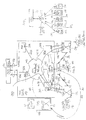
- a first exchange of the communication system 10 comprises a call server 12 coupled to a message switch 14.
- the call server 12 is a processing platform that is able to invoke feature codes and establish call connections, whereas the message switch 14 provides a lower level control interface to the call server.
- the message switch 14 acts to route signalling and control messages to an appropriate one of an ENET switch fabric 16 and a link peripheral processor (LPP) 18 that intercepts signalling messages.
- LPP link peripheral processor
- the call server can set up connections within the ENET switch fabric 16, with the ENET switch fabric 16 coupled to a plurality of peripherals, e.g. Digital Trunk Controllers (DTCs) 20-22.
- DTCs 20-22 provide terminations for individual circuits within trunks.
- a plurality of T1 links 24-26 (each providing twenty-four circuits) couple each DTC 20-22 to a narrowband domain 28 employing, for example, time division multiplexing (TDM).
- TDM time division multiplexing
- Control messages are routed along a dedicated signalling resource 30 and via link peripheral processors (LPPs) of different exchanges (represented by switch (A) 32 and switch (B) 34 within the communication system 10.
- LPPs link peripheral processors
- switch (A) 32 and switch (B) 34 represent switch (A) 32 and switch (B) 34 within the communication system 10.
- signalling information is shared and disseminated within the communication system 10 to allow the setting up of multi-node calls.
- SS7 can reference circuits in a voice route either directly or indirectly.
- the message switch 14 is further coupled to a call server element manager (CSEM) 36, such as a super-node data manager (CSEM), operationally responsive to the call server 12, and arranged to provide functionality such as switch configuration and connection monitoring (for alarm generation, for example); other functions will be readily appreciated.
- CSEM call server element manager
- CSEM super-node data manager
- the ENET switch fabric 16 is further coupled to an interworking unit (IWU) 38 that facilitates broadband-narrowband connection.
- IWU 38 which is managed by the call server 12, provides an interface to a broadband network 40 that uses, for example, ATM techniques for data transport.
- Multi-service platforms (MSPs) 42-44 are coupled to the broadband network 40 through suitable interfaces 45. Although MSPs are generally accessed through the broadband network 40, they are also linked back directly into the narrowband domain and hence to other narrowband nodes 32-34. Each MSP is assigned to a specific call server. The MSP EM 46 manages the MSP platform and its physical interfaces whilst operational data concerning the MSP is sent to and stored by the assigned call server.
- MSH Mobile Multimedia Subsystem
- MSP EM MSP element manager
- MSH EM MSH element manager
- a logical exchange 50 can therefore be formed from all of the above.
- the narrowband system is actually comprised from the call server 12, the message switch 14, the ENET switch fabric 16, DTCs 20-22, the LPP 18 and the IWU 38.
- the exchange 50 may be simplified and the narrowband equipment, namely the ENET switch fabric 16, the DTCs 20-22 and the IWU 38, omitted.
- a direct connection 52 (shown by the dotted arrow) is made between the call server 12 and the broadband network 40.
- LPP functionality is also moved into a signalling server coupled to call server over the broadband network.
- the MSH EM 48 provides a single management point for one or more operations and support system (OSS) 54, with the OSS 54 coupled to the MSH EM 48 through an OSS interface 56.
- OSS operations and support system
- switch (A) 32 i.e. a distantly located and separate exchange from that associated with the exchange 50, connects a first call to switch (B) 34 (associated with another narrowband exchange) via MSP 42, broadband network 40 and MSP 44; and ii) a second connection is coupled through the broadband network 40 from switch (A) to an MSP 242 in a different (second) exchange 250.
- a virtual path could be used to realise a connection of MSPs through the broadband network 40, with the path established by a technique such as phantom trunking, as described in PCT/GB98/02345.
- the general architecture of the second exchange 62 is ostensibly identical to that already described in relation to exchange 50, and by virtue of its interconnection to the ATM (broadband) domain the communication system therefore evolves into a multi-MSH configuration.
- the communication system 10 could, in fact, contain many additional exchanges that are again coupled to the broadband domain to increase the number of MSHs in the communication system 10.
- SS7 signalling between the numerous MSHs therefore ensures consistent operational performance and effective inter-operation.
- the multi-MSH architecture of FIG. 1 provides an ability to process an increased number of BHCAs whilst supporting end-to-end calls through a broadband network, although the system is distributed and contains a plurality of control interfaces to the OSS 54. Indeed, the increased capacity is provided by virtue of the multi-call server configuration, with each call server able to support a finite number of MSPs and BHCAs through them.
- FIG. 2 shows a block diagram 300 of a hierarchical system configuration in a multi-MSH environment according to a preferred embodiment of the present invention.
- an OSS 54 has a single node view with respect to individual MSHs 302-310, which single node view is obtained by virtue of the provisioning of an intermediate MSH element manager (EM 2 ) 312 located between the OSS 54 and the plurality of MSHs 302-310.
- the intermediate EM 2 312 (which has an associated memory 313) is then coupled to each individual MSH element manager 314-322 of each MSH 302-310, with the individual MSH EMs functionally corresponding to that of the MSH EM 48 of FIG. 1.
- the OSS 54 is therefore able to address the intermediate EM 2 312 as though the OSS were merely connected to a solitary MSH, and so signalling, interfacing and operational control from the OSS 54 is consistent with existing techniques.
- the intermediate EM 2 is configured (in a downlink sense) to strip-out system addressing and route to individual MSHs (to be described subsequently) through the use of mapping tables stored in its associated memory 313.
- a second purpose of the intermediate EM 2 312 is to provide a single node reporting point (analogous to the OSS 54) to lower level MSH EMs 314-322. Consequently, the intermediate EM 2 acts to consolidate signalling from the individual MSH EMs to the OSS 54. In this dual role, the intermediate EM 2 ensures that the OSS 54 only receives management information and the like from a single node, and preferably in a format already used to express information between a solitary MSH and the OSS 54.
- the intermediate EM 2 can ensure that the format of information transfer is optimised for receipt by the OSS 54 (taking into account the numerous sources of management information incident to the intermediate EM 2 from the individual MSH EMs 314-322), which process may also involve a protocol translation at the intermediate EM 2 (if required).
- log records from call servers and MSPs are consolidated onto a single flow and identify affected/failed components by name and/or location.
- the intermediate EM 2 can queue management information and the like in its memory 313 for subsequent re-packaging of information into blocks of related data and hence reduced overhead to the OSS and more efficient data transfer, generally.
- the EM 2 can consolidate performance measures from the call servers and MSPs, with the performance measures typically reflecting traffic flows, billing information and semi-permanent virtual channel set-up rates, for example.
- the EM 2 is therefore a logical device realised in a processor-based 323 architecture.
- the intermediate EM 2 also acts to strip-out superfluous data (otherwise destined for the OSS 54) from messages communicated to it by the lower level MSH EMs 314-322, and further acts to translate artificial but assigned MSH addresses into system-wide addresses understandable by the OSS 54; the underlying mechanism and purpose will become apparent later.
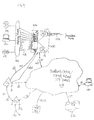
- FIG. 3 a block diagram of an overall communication system architecture 300 and interconnection mechanism of a preferred embodiment of the present invention is shown.
- the intermediate EM 2 312 that has overall interface control between the OSS 54 and individual MSH EMs has been omitted for the sake of clarity.
- the individual MSH EMs 314-322 have been omitted.
- an MSH sub-net 350 is based about a plurality of MSHs 302-308 that are interconnected through a broadband network 40.
- the MSH sub-net 350 further includes a signalling server 352 that is coupled to the broadband network 40 and which logically interconnects each MSH 302-308.
- the signalling server 352 (which is typically realised as a set of control processors) has an associated memory 353 that contains a point code mapping function.
- the signalling server 352 acts to provide an intrinsic MSH sub-net routing function and necessary protocol translation (accessible in terms of a memory retrieval function) for interworking on an intra-MSH basis.
- each MSH 302-308 is connected to the broadband network 40 through an interface 45 to an MSP (not shown).
- the connection is via the IWU or direct from the call server via a direct broadband connection 52.
- a plurality of additional exchanges 32-34 (which may only support narrowband traffic, although they could equally well be mixed nodes (such as other MSH sub-nets) or entirely broadband based) interconnect to individual MSHs 302-308 through real trunks, real circuits and hence real voice paths/routes 354-356.
- the plurality of additional exchanges 32-34 communicate to a signal transfer point (STP) 358 using a control protocol, such as SS7.
- the STP 358 provides a signal routing function, and is further coupled to the signalling server 352.
- the STP is accessible on a system-wide basis from all nodes within the communication system 300.
- the STP function could reside within the signalling server, but the logical picture remains the same. Indeed, the SS7 network configuration, signalling and routing is greatly simplified through consolidation of the signalling server and STP.
- a preferred embodiment contains at least geographically separate signalling servers (and associated STP functionality); one generally acting in a standby capacity.
- Each MSH sub-net 350 is assigned a unique point code address within the narrowband network that acts in an address capacity.
- Each MSH within the sub-net also has a unique but hidden point code that is only accessible on a MSH sub-net level, but not at an inter-exchange level.
- the MSH point codes are selected from a mutually exclusive set of hidden point codes that do not coincide or overlap with the address point codes assigned at an exchange level.
- MSHs within the MSH sub-net 350 are assigned hidden point codes 1001-1004, whereas the MSH sub-net (and particularly its point of entry realised by its dedicated signalling server 352) may have a point code 20 visible on a system-wide basis via the STP 358 and OSS 54.
- Other nodes will have similar (but not identical) codes to the MSH sub-net 350, e.g. the node associated with switch (A) may be referenced as point code 7, whereas the node associated with switch (B) may be point code 13.
- Routing of a call through the MSH sub-net 350 is restricted (for optimised operation) to a passage through a maximum of two MSHs, since an appropriate selection of any two MSHs defines all points of entry and all points of exit in relation to the MSH sub-net 350.
- routing between MSHs occurs through phantom trunks realised by virtual channels in the broadband domain.
- the signalling server 352 traps messages from the STP 358 and then refers to its memory 353 to both interpret the message and then to translate (in the sense of transposing the point code) and finally route the message to a specific MSH within the MSH sub-net.
- a set-up message sent from an external node, such as another exchange or switch, to the MSH sub-net 350 as point code 20 must be interpreted by the signalling server as "message from external node (point code y), address to hidden point code 1XXX of internal MSH".
- a connection is set-up through the use of SS7 signalling to the STP 358, with the originating node sending a message in the exemplary form of: point code of initiating node (FROM XX), circuit identity code associated with data part of message (CIC #), point code of addressed node (TO YY).
- FROM XX point code of initiating node
- CIC # circuit identity code associated with data part of message
- TO YY point code of addressed node
- MSP Internet server
- the message to the STP 358 would initially therefore be (FROM 7, CIC #, TO 20).
- the STP 358 would therefore address the signalling server 352 associated with MSH sub-net 350.
- the signalling server 352 Since the signalling server 352 is aware (by virtual of its pre-provisioned table of point codes, i.e. its point code mapping function) of the external nodes serviceable from a particular MSH, the signalling server 352 can translate (FROM 7, CIC #, TO 20) to (FROM 7, CIC #, TO 1001) in order to take into account the hidden point code and the MSH that is actual addressed.
- the connection between external node 7 and MSH 1001 can therefore be set-up.
- the MSH sub-net represents an intermediate portion of a connection path or route
- dialled digits in the call signalling message from, for example, a calling subscriber terminal 380 will identify the end point and hence the unique call server (and MSH) dedicated to handle the voice route/data connection to an associated exchange assigned to a called party/service 382.
- Each call server can store in associated memory a dial tree, a map of notional destinations and a routing plan in which case the call server of the initially addressed MSH initially refers to its dial tree to identify the succeeding call server in the MSH sub-net and then selects an appropriate routing plan. Once the routing plan has been determined, establishment of the virtual path through the broadband network 40 can be made.
- the dialled digits may, when interpreted, identify external node switch (B) 34 having an address point code 13. Consequently, the call server of the initially addressed MSH references its memory to establish an identity of a second call server associated with an exit point from the MSH sub-net. An information connection is then established (as orchestrated by the respective call servers) between the MSHs in the path of the connection in order that the second call server can subsequently establish the requisite outbound connection from the MSH sub-net; this is entirely transparent at the operations level of the OSS.
- the call server of the initially addressed MSH identifies MSH 304 (having hidden point code 1002) as the exit point from the MSH sub-net 350 in relation to the dialled digits.
- MSH 304 (having hidden point code 1002) is always associated with a particular external node or set of external nodes, and so if it is addressed on an intra MSH sub-net basis then it must act to establish an external connection to the external node identified by the dialled digits.
- the call server of MSH 304 effectively contacts the signalling server 352 which then both associates the connection between the MSH (by virtue of the CIC, for example) and the external exchange and translates the hidden point code 1002 to the point code of the MSH sub-net, i.e. address point code 20.
- the signalling server 352 is then able to send a translated SS7 message identifying the MSH sub-net as an intermediate connection node to the external node identified in the dialled digits. More specifically, the signalling server 352 will operate through the STP 358 that will effectively provide SS7 control signalling to the external node via the dedicated signalling resource 30.
- the end-to-end connection from a first external node via the MSH sub-net 350 to a second external node merely refers to the MSH sub-net as a single entity having a single address point code, with the signalling server 352 effectively disguising the lower level detail of the distributed MSH architecture within the MSH sub-net 350.
- busy routes may have pre-assigned capacity (although this is clearly an arbitrary design choice).
- routing and call server association information (such as which call server is associated with which external node and which specific circuit) is pre-assigned and stored.
- the information required to establish intra-MSH sub-net connections between MSHs may initially reside in the intermediate EM 2 312 and may therefore be downloaded at system start-up or system up-grade either to a particular MSH call server via its associated MSH EM or on an MSH-wide basis, co-ordinated with download to the signalling server 352.
- disaster recovery occurring with MSH failure may be overcome through selective downloading from the intermediate EM 2 to at least one of a standby (and hence otherwise redundant) MSH or an on-line MSH with additional processing/servicing capabilities.
- routing and management information pertaining to a call server/MSH is stored in and utilised by the MSH EM, with the stored information including an indication as to the services offered by individual call servers.
- the spare call server In relation to disaster recovery, following download to a spare call server, the spare call server (at start-up) interrogates its voice routes using such techniques as ISUP maintenance messages to determine trunk busy/free status, and then releases any remaining trunks without call records after expiry of a predetermined time-out.
- Total outage of an MSP is limited by load-sharing each voice route from an external exchange across those MSPs which have been allocated to the MSH that terminates that particular voice route; this results in reduced capacity by no total loss of service.
- the EM 2 312 therefore contains information pertaining to internal, i.e. hidden, point codes associated with each MSH with the MSH sub-net, together with associated dial trees, routing plans, assigned CICs and related external node addresses.
- information may be up-dated, and is always accessible from the OSS for system control.
- the system operates with time-of-day variations in which there is dynamically controlled routing to track and update traffic patterns.
- dynamic control would lead to corresponding changes in routing tables, e.g. the preferred exit points from the MSH sub-net to ultimate destinations may change.
- network billing may involve merging of billing streams from individual call servers at the intermediate EM 2 level.
- billing records could be sent via the intermediate EM 2 from individual call servers, with the hidden point code either translated into that of the MSH sub-net address point code, or retained to differentiate a billing area, e.g. a higher call-charge rate for central Manhattan as opposed to an area in the vicinity of the far east of Long Island.
- the intermediate EM 2 can function to correlate billing records from the two call managers involved in a call across the MSH sub-net 350 and therefore to provide a single consolidated record for each call.
- a first aspect of the present invention provides a sub-net management layer with applications that hide the details of individual MSH nodes from the higher-level OSS operations system; this is realised by the intermediate EM 2 312.
- Functionality provided to the intermediate EM 2 includes that required to: configure the MSH sub-net; install and configure both call servers, access boxes (i.e. MSPs) and voice routes; define and map community of interest information pertaining to traffic capacity requirements between external nodes onto provisioned internal phantom trunk groups; manage time of day traffic variations; and manage the flow of information back to the OSS (e.g. by consolidating logs, performance data and call records from individual MSHs).
- SS7 signalling is consolidated into a unique externally visible point code, whereby a robust and scalable signalling server is configured to convert between a single point code (indicative of the MSH sub-net as a single switch) and internal point codes assigned on a unique basis to each MSH node.
- the system operator therefore perceives the MSH sub-net 350 as a single exchange in which switching occurs between external TDM voice routes (in a hybrid narrowband-MSH sub-net configuration).
- an intermediate element manager acts both to unify reporting channels whilst also distributing control information from an OSS is applicable to other communication networks, since the intermediate element manager (in essence) maintains existing information flows between an operations and system management level of a communication system and lower level network equipment concerned principally with actual path and route establishment. Moreover, the intermediate element manager supports and growth and development of an existing system whilst maintaining an established signalling and control protocol.
- FIG. 4 With regard to a typical implementation of the underlying principles of the present invention to an Internet protocol (IP) environment, reference is made FIG. 4.
- a remote access server (RAS) 400 is provided with a unique point code since it acts in an analogous fashion to a logical exchange and therefore can be addressed as a single entity.
- the RAS 400 typically includes a switch 33 and a MSP 43; these may be collocated.
- the RAS is coupled to broadband/ATM/Internet Protocol (IP) domain 401 through an IP communication resource 402, while the MSP 43 also interfaces to a plurality of narrowband trunks 404.
- IP Internet Protocol
- the RAS 400 also includes a bank of modems 406 that can be dynamically assigned to one of a number of different communication channels, typically supported on communication resources 408 of a telephony-type network 410.
- the communication resources may be wireline resources such as optical fibres, copper pairs or the like, although the communication resources could also be realised in a radio frequency environment.
- the communication resources 408 ultimately interconnect to dedicated subscriber equipment, such as a computer 410, a modem 412 or a suitably configured telephone device 414.
- the RAS 400 (which is also shown in FIG. 3) is further coupled to call servers 12 and 212 associated with the general system configuration through at least one common signalling channel supporting SS7.
- the call servers are themselves coupled to the broadband/ATM/Internet Protocol (IP) domain 401 through suitable (and preferably broadband) interfaces 52, 52' that support the Internet protocol (or its functional equivalent). IP will also be used to provide a communication protocol to interface the broadband/ATM/Internet Protocol (IP) domain 401 with an Internet service provider 420 or other data repository 422 (or the like).
- IP Internet Protocol
- the computer In relation to the establishment of an IP-based communication between, say, computer 410 and Internet service provider 420, the computer initially exercises a dial-up scheme (such as IP access in Internet telephony) to the RAS 400.
- the RAS 400 immediately selects and assigns an available modem to the call from its bank of modems 406.
- the RAS 400 then effectively signals a call server associated with the Internet service provider 420; this is achieved through the use of the signalling server 352 that functions in accordance with the connection strategy already detailed above and specifically in relation to FIG. 3.
- the signalling server and its associated STP 358 have been omitted from FIG. 4 for the purposes of clarity, although it will clearly be appreciated that the signalling server and STP function to intercept, interpret and forward signalling control messages between logical exchanges, call servers and MSHs. The signalling server therefore passes off relevant messages to an identified call server.
- the identified call server Once the identified call server is in receipt of the message from the signalling server it becomes aware of the existence of a connection requirement.
- the identified call server through the use of a control channel and associated signalling scheme (e.g. MGCP), is configured to notify the RAS 400 that it can, in fact, directly route IP and hence establish a point-to-point IP communication between the computer 410 and Internet service provider 420 via the broadband/ATM/Internet Protocol (IP) domain 401. Consequently, the RAS 400 is able to release (i.e. drop) the modem that was initially required to establish connection from the computer 410 to the RAS, which modem is therefore freed for contemporaneous use in another call or connection event.
- a control channel and associated signalling scheme e.g. MGCP
- the underlying inventive concept of the present invention can be enhanced through the assignment of multiple unique point codes to the MSH subnet 350, with each MSH 302-308 also potentially having more than one point code (although multiple point codes assigned to MSHs will only be visible within the confines of the MSH subnet 350).
- the MSH subnet 350 can present more than one point code to the rest of the communication network or system; this is advantageous in relation to the presentation of multiple virtual nodes that can be used, for example, in an international exchange that straddles a plurality of country boundaries.
- the MSH subnet 350 may therefore appear in more than one network simultaneously and even to the extent that it has a different network indicator and it uses a different protocol (e.g.
- each MSH now has at least one point code assigned to it, any one of the collection of all the assigned point codes within the MSH subnet still uniquely identifies the MSH subnet 350.
- the use of multiple assigned point codes can also be used to increase SS7 signalling capacity by permitting the implementation of parallel linksets between the signalling server 352 and the STP 358 where call processing is partitioned between virtual nodes within the MSH subnet 350.
- a service control point (SCP) 450 is coupled through a control interface to the STP 358.
- SCP service control point
- TCAP/SCCP over SS7 is a protocol used in relation to queries generated between MSHs 302-308 and databases or data repositories, and when exchanges 32-34 query the MSH subnet 350.
- MSH subnet 350 there is a similar routing strategy in the MSH subnet 350, although routing involves a slightly different level of detail.
- signalling between the logical exchanges could also use TCAP/SCCP and so the signalling resource 30 would be configured accordingly.
- the handling of TCAP/SCCP over SS7 may be sub-system specific. For those sub-systems where the data is local to a particular MSH 302-308 internal to the MSH subnet 350 (such as in relation to certain CLASS services associated with particular directory numbers), the TCAP message is decoded by the signalling server function and the directory number extracted for use as an index into the point code mapping function.
- sub-system handling could, in some cases and as desired, be completely handled in the signalling server 352; this occurs when the data or function (such as a routing verification test) is common to all MSHs 302-308 within the MSH subnet 350.
- TCAP message is augmented by suitable mapping information, such as a transaction identify (“TRID”) mapping function, to facilitate routing of the return message of information.
- TID transaction identify
Abstract
Description
Advantageously, the present invention provides a communication system with a uniform operational and signalling perspective whilst beneficially maintaining a distributed architecture that inherently supports system recovery from individual exchange failures. In other words, the distributed nature of a multi-MSH environment is hidden from a service provider, whilst the system is robust and able to support re-routing should any individual MSH suffers a temporary but fatal system failure. Consequently, an operator is provided with a single node view from the perspective of an operations layer, whilst each exchange perceives the intermediate element manager as a network manager and is therefore beneficially oblivious of other exchanges/MSHs within the communication system. Moreover, the preferred embodiment of the present invention supports a significant increase in system handling capacity whilst maintaining an underlying network architecture of existing narrowband systems. Furthermore, migration to a fully-fledged broadband (access) network is supported through relatively simply modification of system connectivity.
Claims (48)
- A communication system comprising:a plurality of multi-service hubs (MSH), each MSH comprising an exchange having at least one multi-service platform (MSP), the exchange and the at least one MSP managed by an element manager that co-ordinates management thereof;an operations and support system (OSS) providing a control interface to an operator of the communication system; andan intermediate element manager coupled to each element manager in each MSH, the intermediate element manager further coupled to the OSS and configured to intercept system management information passed between the OSS and each of the element managers such that the intermediate element manager provides a single address point to the OSS while also appearing to be an OSS to each element manager in each MSH.
- The communication system of claim 1, wherein the intermediate element manager comprises:a memory containing a connection map; andmeans, coupled to the connection memory, for stripping-out system addressing incident to the intermediate element manager from the OSS and for routing system management information to individual MSHs through use of the connection map.
- The communication system of claim 1 or 2, wherein the intermediate element manager comprises:means of consolidating information from each element manager in each MSH to the OSS, thereby ensuring that the OSS receives system management information from a single node only.
- The communication system of claim 3, wherein each of the plurality of MSHs contains an associated call server, and the means of consolidating information consolidates, onto a single flow, at least one of:log records from call servers and MSPs; andperformance measures from the call servers and MSPs, said the performance measures typically reflecting traffic flows, billing information and semi-permanent virtual channel set-up rates.
- The communication system of claim 4, wherein the means for consolidating information further includes means for identifying affected/failed system entities by at least one of name and location.
- The communication system of claim 1, the intermediate element manager further comprising means for queuing system management information and means for re-packaging said system management information into blocks of related data.
- The communication system of claim 1, wherein the intermediate element manager is configured to strip-out superfluous data from messages communicated to it by the each of the element managers.
- The communication system of claim 1, wherein the intermediate element manager further comprises means for translating artificial but assigned MSH addresses into system-wide addresses understandable by the OSS.
- The communication system of claim 1, wherein the intermediate element manager further comprises means for performing additional management functionality.
- The communication system of claim 1, wherein the intermediate element manager further comprises means for merging billing streams emanating from each MSH (314-322) to produce a network billing record.
- The communication system of claim 4, wherein in the intermediate element manager further comprises means for correlating billing records from a plurality of call managers involved in a call across the communication system, thereby providing a single consolidated record for each call.
- A method of managing a communication system comprising a plurality of multi-service hubs (MSH) each having an exchange with at least one multi-service platform (MSP), the exchange and the at least one MSP managed by an element manager that co-ordinates management thereof, the communication system further comprising an operations and support system (OSS) providing a control interface to an operator of the communication system and an intermediate element manager interconnecting each element manager in each MSH and the OSS, the method comprising:restricting a passage of system management information between the OSS and selected ones of the plurality of element managers to a path via the intermediate network manager, such that the intermediate element manager provides a single address point to the OSS while also appearing to be an OSS to each element manager in each MSH.
- The method of managing a communication system according to claim 12, the intermediate element manager comprises a memory containing a connection map, the method further comprising:stripping-out system addressing incident to the intermediate element manager from the OSS; androuting system management information to individual MSHs through use of the connection map.
- The method of managing a communication system according to claim 13, further comprising:in the intermediate element manager, consolidating information from each element manager in each MSH to the OSS, thereby to ensure that the OSS receives system management information from a single node only.
- The method of managing a communication system according to claim 14, wherein each of the plurality of MSHs contains an associated call server, and the method of consolidating consolidates, onto a single flow, at least one of:log records from call servers and MSPs; andperformance measures from the call servers and MSPs, said the performance measures typically reflecting traffic flows, billing information and semi-permanent virtual channel set-up rates.
- The method of managing a communication system according to claim 14, wherein the consolidating information further includes identifying affected/failed system entities by at least one of name and location.
- The method of managing a communication system according to claim 12, further comprising:at the intermediate element manager, queuing system management information; andre-packaging said system management information into blocks of related data.
- The method of managing a communication system according to claim 12, further comprising:at the intermediate element manager, stripping-out superfluous data from messages communicated to it by the each of the element managers.
- The method of managing a communication system according to claim 12, further comprising:at the intermediate element manager, translating artificial but assigned MSH addresses into system-wide addresses understandable by the OSS.
- The method of managing a communication system according to claim 12, further comprising:at the intermediate element manager, merging billing streams emanating from each MSH to produce a network billing record.
- The method of managing a communication system according to claim 14, further comprising:at the intermediate element manager, correlating billing records from a plurality of call managers involved in a call across the communication system, thereby providing a single consolidated record for each call.
- The method of managing a communication system according to claim 14, further comprising:associating a unique hidden point code with each of the plurality of multi-service hubs (MSH); and one of the steps of:translating unique hidden point codes into an MSH sub-net address point code; andcommunicating an indication of the hidden point codes to indicate to the OSS a relative billing level between different geographic areas serviced by different MSHs having different hidden point codes.
- A communication system comprising a plurality of logical exchanges each assigned a unique address point code, at least one of said logical exchanges being a sub-network containing a plurality of multi-service hubs interconnectable to one another through a broadband domain, each multi-service hub further coupled through communication resources to at least one of the remaining logical exchanges, each multi-service hub further being uniquely assigned a hidden point code different to any of the address point codes assigned to the logical exchanges, and wherein the hidden point codes:support interconnection of a first MSH to a second MSH through the broadband domain; andare inaccessible from a connection perspective from outside the sub-network.
- The communication system according to claim 23, further comprising means for converting between an address point code and a hidden point code.
- The communication system according to claim 24, wherein the means for converting translates a first address point code of the sub-network into a first hidden point code associated with an MSH entry point into the sub-network and further translates a second hidden point code associated with an MSH exit point from the sub-network into the address point code in onward routing of signalling messages to a destination address associated with one of said remaining logical exchanges.
- The communication system according to claim 23, wherein said remaining logical exchanges are coupled to the means for converting between an address point code and a hidden point code.
- The communication system according to claim 23, wherein said remaining logical exchange communicate with the means for converting using a common protocol, and preferably SS7.
- The communication system according to claim 23, wherein said means for converting comprises:a signal transfer point (STP) providing a signal routing function and accessible by the plurality of logical exchanges; anda signalling server 352 coupled to the STP, the signalling server further coupled to the broadband domain and arranged to logically interconnect each MSH and to provide a sub-network routing function for interworking on an intra-MSH basis.
- The communication system according to claim 28, wherein the signalling server has an associated memory that contains a point code mapping function between address point codes and hidden point codes.
- The communication system according to claim 28, wherein functionality of the STP is collocated with the signalling server.
- The communication system according to claim 23, wherein each multi-service hub is assigned at least one unique hidden point code different to any of the address point codes assigned to the logical exchanges.
- The communication system according to claim 23, wherein the sub-network is assigned a plurality of unique address point codes.
- A method of establishing a connection across an intermediate sub-network containing a plurality of multi-service hubs interconnectable to one another through a broadband domain, each multi-service hub further coupled through communication resources to at least one logical exchange external to the sub-network, the method comprising:assigning individual address point codes to each logical exchange external to the sub-network and also to the sub-network; anduniquely assigning at least one hidden point code, different to any of the address point codes assigned to the logical exchanges, to each multi-service hub, and wherein the hidden point codes are inaccessible from a connection perspective from outside the sub-network.
- The method of establishing a connection across an intermediate sub-network according to claim 33, further comprising:establishing a connection between a first logical exchange having a first address point code and a second logical exchange having a second address point code via a first MSH having a first hidden point code, a second MSH having a second hidden point code and the broadband domain, and wherein establishing the connection further comprises:converting between an address point code and a hidden point code upon entry into and exit from the sub-network.
- The method of establishing a connection across an intermediate sub-network according to claim 33, wherein each multi-service hub is assigned at least one unique hidden point code, each of said at least one unique hidden code being selectively accessible.
- The method of establishing a connection according to claim 34, wherein the establishing the connection further comprises:translating the address point code of the sub-network into the first hidden point code associated with an MSH entry point into the sub-network; andtranslating the second hidden point code associated with an MSH exit point from the sub-network into the second address point code associated with a destination address of the second logical exchange.
- The method of establishing a connection according to claim 34, further comprising:providing a database that cross-references hidden point codes and point codes addresses;obtaining an indication of the MSH exit point from dialled digits emanating from the first logical exchange;determining the second hidden point code from the database; andproviding a path between the MSH entry point and the MSH exit point.
- An intermediate element manager for a communication system comprising a plurality of multi-service hubs (MSH) each having an exchange with at least one multi-service platform (MSP), the exchange and the at least one MSP managed by an element manager that co-ordinates management thereof, the communication system further comprising an operations and support system (OSS) providing a control interface to an operator of the communication system, wherein:the intermediate element manager is arranged to be coupled to each element manager in each MSH and also to be coupled to the OSS, the intermediate element manager configured to intercept system management information passed between the OSS and each of the element managers such that the intermediate element manager provides a single address point to the OSS while also appearing to be an OSS to each element manager in each MSH and such that the intermediate element manager relays system management information between the OSS to each element manager.
- The intermediate element manager according to claim 38, further comprising:a memory containing a connection map; andmeans, coupled to the connection memory, for stripping-out system addressing incident to the intermediate element manager from the OSS and for routing system management information to individual MSHs through use of the connection map.
- The intermediate element manager according to claim 38, further comprising:means of consolidating information from each element manager in each MSH to the OSS 54, thereby ensuring that the OSS 54 receives system management information from a single node only.
- The intermediate element manager according to claim 38, wherein each of the plurality of MSHs contains an associated call server, and the means of consolidating information consolidates, onto a single flow, at least one of:log records from call servers and MSPs; andperformance measures from the call servers and MSPs, said the performance measures typically reflecting traffic flows, billing information and semi-permanent virtual channel set-up rates.
- The intermediate element manager according to claim 40, wherein the means for consolidating information further includes means for identifying affected/failed system entities by at least one of name and location.
- The intermediate element manager according to claim 38, further comprising means for queuing system management information and means for re-packaging said system management information into blocks of related data.
- The intermediate element manager according to claim 38, wherein the intermediate element manager is configured to strip-out superfluous data from messages communicated to it by the each of the element managers.
- The intermediate element manager according to claim 38, further comprising means for translating artificial but assigned MSH addresses into system-wide addresses understandable by the OSS 54.
- The intermediate element manager according to claim 38, further comprising means for performing additional management functionality.
- The intermediate element manager according to claim 38, further comprising means for merging billing streams emanating from each MSH (314-322) to produce a network billing record.
- The intermediate element manager according to claim 41, further comprising means for correlating billing records from a plurality of call managers involved in a call across the communication system, thereby providing a single consolidated record for each call.
Applications Claiming Priority (2)
| Application Number | Priority Date | Filing Date | Title |
|---|---|---|---|
| GBGB9828582.8A GB9828582D0 (en) | 1998-12-23 | 1998-12-23 | Communication system architecture apparatus and method of call handling |
| GB9828582 | 1998-12-23 |
Publications (2)
| Publication Number | Publication Date |
|---|---|
| EP1014744A2 true EP1014744A2 (en) | 2000-06-28 |
| EP1014744A3 EP1014744A3 (en) | 2005-08-10 |
Family
ID=10844993
Family Applications (1)
| Application Number | Title | Priority Date | Filing Date |
|---|---|---|---|
| EP99307965A Withdrawn EP1014744A3 (en) | 1998-12-23 | 1999-10-08 | Communication system architecture, apparatus and management and signalling method therein |
Country Status (4)
| Country | Link |
|---|---|
| US (1) | US6356627B1 (en) |
| EP (1) | EP1014744A3 (en) |
| CA (1) | CA2286424C (en) |
| GB (1) | GB9828582D0 (en) |
Cited By (1)
| Publication number | Priority date | Publication date | Assignee | Title |
|---|---|---|---|---|
| US9680798B2 (en) | 2014-04-11 | 2017-06-13 | Nant Holdings Ip, Llc | Fabric-based anonymity management, systems and methods |
Families Citing this family (14)
| Publication number | Priority date | Publication date | Assignee | Title |
|---|---|---|---|---|
| DE59806566D1 (en) * | 1998-04-22 | 2003-01-16 | Siemens Ag | SIGNALING DEVICE IN A SIGNALING SYSTEM |
| US7657330B2 (en) * | 1999-06-11 | 2010-02-02 | Parker-Hannifin Corporation | Optical ring architecture |
| JP2001144759A (en) * | 1999-11-12 | 2001-05-25 | Fujitsu Ltd | Communication network management system, sub communication network managing device used for the communication network management system, communication network managing device and computer readable recording medium with program recorded thereon |
| US7002915B1 (en) * | 1999-11-22 | 2006-02-21 | Alcatel Canada Inc. | Automated mass calling control for public switched telephone networks employing a packet based virtual tandem |
| US6674748B1 (en) | 1999-12-21 | 2004-01-06 | Telefonaktiebolaget Lm Ericsson (Publ) | Methods, apparatuses and systems for transitioning from a signaling system 7 network to a data network at a signaling system 7 gateway |
| US6747980B1 (en) * | 1999-12-21 | 2004-06-08 | Ericsson Inc. | Methods, apparatuses and systems for managing multiple signaling end points in a signaling system 7 network |
| US7039175B1 (en) * | 2000-06-02 | 2006-05-02 | Cisco Technology, Inc. | Configurable digit collection for various signaling protocols |
| US6947724B2 (en) * | 2002-01-04 | 2005-09-20 | Telefonaktiebolaget Lm Ericsson (Publ) | System and method of billing based on the reported traffic load in a telecommunications network |
| WO2004045141A1 (en) * | 2002-11-12 | 2004-05-27 | Nokia Corporation | Method for avoiding double charging of a service in a telecommunication system |
| US7474661B2 (en) * | 2004-03-26 | 2009-01-06 | Samsung Electronics Co., Ltd. | Apparatus and method for distributing forwarding table lookup operations among a plurality of microengines in a high-speed routing node |
| GB2431067B (en) | 2005-10-07 | 2008-05-07 | Cramer Systems Ltd | Telecommunications service management |
| GB2432992B (en) * | 2005-11-18 | 2008-09-10 | Cramer Systems Ltd | Network planning |
| GB2433675B (en) * | 2005-12-22 | 2008-05-07 | Cramer Systems Ltd | Communications circuit design |
| GB2435362B (en) * | 2006-02-20 | 2008-11-26 | Cramer Systems Ltd | Method of configuring devices in a telecommunications network |
Citations (2)
| Publication number | Priority date | Publication date | Assignee | Title |
|---|---|---|---|---|
| US5768501A (en) * | 1996-05-28 | 1998-06-16 | Cabletron Systems | Method and apparatus for inter-domain alarm correlation |
| WO1998026541A1 (en) * | 1996-12-13 | 1998-06-18 | 3Com Corporation | Improved distributed remote monitoring (drmon) for networks |
Family Cites Families (8)
| Publication number | Priority date | Publication date | Assignee | Title |
|---|---|---|---|---|
| US6034678A (en) * | 1991-09-10 | 2000-03-07 | Ictv, Inc. | Cable television system with remote interactive processor |
| US5790548A (en) * | 1996-04-18 | 1998-08-04 | Bell Atlantic Network Services, Inc. | Universal access multimedia data network |
| US6308328B1 (en) * | 1997-01-17 | 2001-10-23 | Scientific-Atlanta, Inc. | Usage statistics collection for a cable data delivery system |
| US6141339A (en) * | 1997-04-04 | 2000-10-31 | Sprint Communications Company, L.P. | Telecommunications system |
| US6157378A (en) * | 1997-07-02 | 2000-12-05 | At&T Corp. | Method and apparatus for providing a graphical user interface for a distributed switch having multiple operators |
| US5910988A (en) * | 1997-08-27 | 1999-06-08 | Csp Holdings, Inc. | Remote image capture with centralized processing and storage |
| US6011548A (en) * | 1998-09-04 | 2000-01-04 | Cyberstar, L.P. | System for integrating satellite boardband data distributed over a cable TV network with legacy corporate local area networks |
| US6252952B1 (en) * | 1999-12-30 | 2001-06-26 | At&T Corp | Personal user network (closed user network) PUN/CUN |
-
1998
- 1998-12-23 GB GBGB9828582.8A patent/GB9828582D0/en not_active Ceased
-
1999
- 1999-04-20 US US09/295,196 patent/US6356627B1/en not_active Expired - Lifetime
- 1999-10-08 EP EP99307965A patent/EP1014744A3/en not_active Withdrawn
- 1999-10-18 CA CA002286424A patent/CA2286424C/en not_active Expired - Lifetime
Patent Citations (2)
| Publication number | Priority date | Publication date | Assignee | Title |
|---|---|---|---|---|
| US5768501A (en) * | 1996-05-28 | 1998-06-16 | Cabletron Systems | Method and apparatus for inter-domain alarm correlation |
| WO1998026541A1 (en) * | 1996-12-13 | 1998-06-18 | 3Com Corporation | Improved distributed remote monitoring (drmon) for networks |
Non-Patent Citations (1)
| Title |
|---|
| ATM FORUM: "Circuit Emulation Service Interoperability Specification Version 2.0" ATM FORUM TECHNICAL COMMITTE, [Online] January 1997 (1997-01), XP002321959 Retrieved from the Internet: URL:www.atmforum.org> [retrieved on 2005-03-22] * |
Cited By (4)
| Publication number | Priority date | Publication date | Assignee | Title |
|---|---|---|---|---|
| US9680798B2 (en) | 2014-04-11 | 2017-06-13 | Nant Holdings Ip, Llc | Fabric-based anonymity management, systems and methods |
| US9973476B2 (en) | 2014-04-11 | 2018-05-15 | Nant Holdings Ip, Llc | Fabric-based anonymity management, systems and methods |
| US10356049B2 (en) | 2014-04-11 | 2019-07-16 | Nant Holdings Ip, Llc | Fabric-based anonymity management, systems and methods |
| US10931639B2 (en) | 2014-04-11 | 2021-02-23 | Nant Holdings Ip, Llc | Fabric-based anonymity management, systems and methods |
Also Published As
| Publication number | Publication date |
|---|---|
| US6356627B1 (en) | 2002-03-12 |
| GB9828582D0 (en) | 1999-02-17 |
| EP1014744A3 (en) | 2005-08-10 |
| CA2286424A1 (en) | 2000-06-23 |
| CA2286424C (en) | 2007-08-07 |
Similar Documents
| Publication | Publication Date | Title |
|---|---|---|
| US7675853B2 (en) | Communication system architecture and operating methods thereof | |
| EP0948235B1 (en) | Communication system architecture and a connection verification mechnism therefor | |
| US6496508B1 (en) | Communication system architecture and method of establishing a communication connection therein | |
| US6028858A (en) | ANI-dormant connections for frame relay | |
| AU742135B2 (en) | Communication system architecture and a management control agent and operating protocol therefor | |
| EP0926920B1 (en) | Communication system architecture and operating protocol therefor | |
| CA2286424C (en) | Communication system architecture, apparatus and management and signalling method therein | |
| US6570868B1 (en) | System and method for establishing a communication connection | |
| CA2254821A1 (en) | Communications system with load sharing communications interface | |
| US6882721B2 (en) | Method and apparatus enabling local number portability in telephone networks | |
| EP1590968B1 (en) | Remote switch and method for connecting to and providing IP access and services to a TDM network | |
| US20020181487A1 (en) | Automation of provisioning of private line packet network connections | |
| Forchtner et al. | An ISDN solution for heterogeneous PBX networking |
Legal Events
| Date | Code | Title | Description |
|---|---|---|---|
| PUAI | Public reference made under article 153(3) epc to a published international application that has entered the european phase |
Free format text: ORIGINAL CODE: 0009012 |
|
| AK | Designated contracting states |
Kind code of ref document: A2 Designated state(s): AT BE CH CY DE DK ES FI FR GB GR IE IT LI LU MC NL PT SE |
|
| AX | Request for extension of the european patent |
Free format text: AL;LT;LV;MK;RO;SI |
|
| RAP1 | Party data changed (applicant data changed or rights of an application transferred) |
Owner name: NORTEL NETWORKS LIMITED |
|
| RAP1 | Party data changed (applicant data changed or rights of an application transferred) |
Owner name: NORTEL NETWORKS LIMITED |
|
| RIC1 | Information provided on ipc code assigned before grant |
Ipc: 7H 04Q 11/04 B Ipc: 7H 04L 12/24 B Ipc: 7H 04Q 11/00 A |
|
| PUAL | Search report despatched |
Free format text: ORIGINAL CODE: 0009013 |
|
| AK | Designated contracting states |
Kind code of ref document: A3 Designated state(s): AT BE CH CY DE DK ES FI FR GB GR IE IT LI LU MC NL PT SE |
|
| AX | Request for extension of the european patent |
Extension state: AL LT LV MK RO SI |
|
| STAA | Information on the status of an ep patent application or granted ep patent |
Free format text: STATUS: THE APPLICATION HAS BEEN WITHDRAWN |
|
| 18W | Application withdrawn |
Effective date: 20051011 |
|
| RIN1 | Information on inventor provided before grant (corrected) |
Inventor name: PROZENIUK, PERRY L. Inventor name: HAYBALL, CLIVE COLIN |