EP1013497A2 - Automated transmission downshift control - Google Patents
Automated transmission downshift control Download PDFInfo
- Publication number
- EP1013497A2 EP1013497A2 EP99124892A EP99124892A EP1013497A2 EP 1013497 A2 EP1013497 A2 EP 1013497A2 EP 99124892 A EP99124892 A EP 99124892A EP 99124892 A EP99124892 A EP 99124892A EP 1013497 A2 EP1013497 A2 EP 1013497A2
- Authority
- EP
- European Patent Office
- Prior art keywords
- brake system
- engine
- foot brake
- engine speed
- sensed
- Prior art date
- Legal status (The legal status is an assumption and is not a legal conclusion. Google has not performed a legal analysis and makes no representation as to the accuracy of the status listed.)
- Granted
Links
Images


Classifications
-
- B—PERFORMING OPERATIONS; TRANSPORTING
- B60—VEHICLES IN GENERAL
- B60W—CONJOINT CONTROL OF VEHICLE SUB-UNITS OF DIFFERENT TYPE OR DIFFERENT FUNCTION; CONTROL SYSTEMS SPECIALLY ADAPTED FOR HYBRID VEHICLES; ROAD VEHICLE DRIVE CONTROL SYSTEMS FOR PURPOSES NOT RELATED TO THE CONTROL OF A PARTICULAR SUB-UNIT
- B60W10/00—Conjoint control of vehicle sub-units of different type or different function
- B60W10/18—Conjoint control of vehicle sub-units of different type or different function including control of braking systems
-
- B—PERFORMING OPERATIONS; TRANSPORTING
- B60—VEHICLES IN GENERAL
- B60W—CONJOINT CONTROL OF VEHICLE SUB-UNITS OF DIFFERENT TYPE OR DIFFERENT FUNCTION; CONTROL SYSTEMS SPECIALLY ADAPTED FOR HYBRID VEHICLES; ROAD VEHICLE DRIVE CONTROL SYSTEMS FOR PURPOSES NOT RELATED TO THE CONTROL OF A PARTICULAR SUB-UNIT
- B60W10/00—Conjoint control of vehicle sub-units of different type or different function
- B60W10/10—Conjoint control of vehicle sub-units of different type or different function including control of change-speed gearings
- B60W10/11—Stepped gearings
- B60W10/111—Stepped gearings with separate change-speed gear trains arranged in series
-
- B—PERFORMING OPERATIONS; TRANSPORTING
- B60—VEHICLES IN GENERAL
- B60W—CONJOINT CONTROL OF VEHICLE SUB-UNITS OF DIFFERENT TYPE OR DIFFERENT FUNCTION; CONTROL SYSTEMS SPECIALLY ADAPTED FOR HYBRID VEHICLES; ROAD VEHICLE DRIVE CONTROL SYSTEMS FOR PURPOSES NOT RELATED TO THE CONTROL OF A PARTICULAR SUB-UNIT
- B60W30/00—Purposes of road vehicle drive control systems not related to the control of a particular sub-unit, e.g. of systems using conjoint control of vehicle sub-units, or advanced driver assistance systems for ensuring comfort, stability and safety or drive control systems for propelling or retarding the vehicle
- B60W30/18—Propelling the vehicle
- B60W30/18009—Propelling the vehicle related to particular drive situations
- B60W30/18109—Braking
- B60W30/18136—Engine braking
-
- F—MECHANICAL ENGINEERING; LIGHTING; HEATING; WEAPONS; BLASTING
- F16—ENGINEERING ELEMENTS AND UNITS; GENERAL MEASURES FOR PRODUCING AND MAINTAINING EFFECTIVE FUNCTIONING OF MACHINES OR INSTALLATIONS; THERMAL INSULATION IN GENERAL
- F16H—GEARING
- F16H61/00—Control functions within control units of change-speed- or reversing-gearings for conveying rotary motion ; Control of exclusively fluid gearing, friction gearing, gearings with endless flexible members or other particular types of gearing
- F16H61/21—Providing engine brake control
-
- B—PERFORMING OPERATIONS; TRANSPORTING
- B60—VEHICLES IN GENERAL
- B60W—CONJOINT CONTROL OF VEHICLE SUB-UNITS OF DIFFERENT TYPE OR DIFFERENT FUNCTION; CONTROL SYSTEMS SPECIALLY ADAPTED FOR HYBRID VEHICLES; ROAD VEHICLE DRIVE CONTROL SYSTEMS FOR PURPOSES NOT RELATED TO THE CONTROL OF A PARTICULAR SUB-UNIT
- B60W2510/00—Input parameters relating to a particular sub-units
- B60W2510/06—Combustion engines, Gas turbines
- B60W2510/0638—Engine speed
-
- B—PERFORMING OPERATIONS; TRANSPORTING
- B60—VEHICLES IN GENERAL
- B60W—CONJOINT CONTROL OF VEHICLE SUB-UNITS OF DIFFERENT TYPE OR DIFFERENT FUNCTION; CONTROL SYSTEMS SPECIALLY ADAPTED FOR HYBRID VEHICLES; ROAD VEHICLE DRIVE CONTROL SYSTEMS FOR PURPOSES NOT RELATED TO THE CONTROL OF A PARTICULAR SUB-UNIT
- B60W2510/00—Input parameters relating to a particular sub-units
- B60W2510/06—Combustion engines, Gas turbines
- B60W2510/069—Engine braking signal
-
- B—PERFORMING OPERATIONS; TRANSPORTING
- B60—VEHICLES IN GENERAL
- B60W—CONJOINT CONTROL OF VEHICLE SUB-UNITS OF DIFFERENT TYPE OR DIFFERENT FUNCTION; CONTROL SYSTEMS SPECIALLY ADAPTED FOR HYBRID VEHICLES; ROAD VEHICLE DRIVE CONTROL SYSTEMS FOR PURPOSES NOT RELATED TO THE CONTROL OF A PARTICULAR SUB-UNIT
- B60W2540/00—Input parameters relating to occupants
- B60W2540/12—Brake pedal position
-
- F—MECHANICAL ENGINEERING; LIGHTING; HEATING; WEAPONS; BLASTING
- F16—ENGINEERING ELEMENTS AND UNITS; GENERAL MEASURES FOR PRODUCING AND MAINTAINING EFFECTIVE FUNCTIONING OF MACHINES OR INSTALLATIONS; THERMAL INSULATION IN GENERAL
- F16H—GEARING
- F16H61/00—Control functions within control units of change-speed- or reversing-gearings for conveying rotary motion ; Control of exclusively fluid gearing, friction gearing, gearings with endless flexible members or other particular types of gearing
- F16H61/70—Control functions within control units of change-speed- or reversing-gearings for conveying rotary motion ; Control of exclusively fluid gearing, friction gearing, gearings with endless flexible members or other particular types of gearing specially adapted for change-speed gearing in group arrangement, i.e. with separate change-speed gear trains arranged in series, e.g. range or overdrive-type gearing arrangements
- F16H61/702—Control functions within control units of change-speed- or reversing-gearings for conveying rotary motion ; Control of exclusively fluid gearing, friction gearing, gearings with endless flexible members or other particular types of gearing specially adapted for change-speed gearing in group arrangement, i.e. with separate change-speed gear trains arranged in series, e.g. range or overdrive-type gearing arrangements using electric or electrohydraulic control means
Definitions
- the present invention relates to a control method/system for controlling downshifting in an at least partially automated mechanical transmission system.
- the present invention relates to the control of downshifting in a vehicular automated mechanical transmission system wherein the system senses operation of an engine brake and the vehicle service brakes (also called foot brakes) and will modify downshift points as a function thereof.
- An object of the present invention is to provide a control for a vehicular automated mechanical transmission system which will sense the operator's manual operation of the engine brake and/or foot brake systems and will modify the transmission shift points as a function thereof.
- the transmission downshift shift points will be modified in a manner which will provide the vehicle operator with the level of engine braking perceived to be requested by his/her operation of the engine brake and/or foot brake control.
- the automated transmission system 10 includes a fuel-controlled engine 12 (such as a well-known diesel engine or the like), a multiple-speed, change-gear transmission 14, and a non-positive coupling 16 (such as a friction master clutch) drivingly interposed between the engine and the input shaft 18 of the transmission.
- the transmission 14 may be of the compound type comprising a main transmission section connected in series with a splitter- and/or range-type auxiliary section. Transmissions of this type, especially as used with heavy-duty vehicles, typically have 9, 10, 12, 13, 16 or 18 forward speeds. Examples of such transmissions may be seen by reference to U.S. Pats. No. 5,390,561 and 5,737,978, the disclosures of which are incorporated herein by reference.
- a microprocessor-based electronic control unit (or ECU) 28 is provided for receiving input signals 30 and for processing same in accordance with predetermined logic rules to issue command output signals 32 to various system actuators and the like.
- Microprocessor-based controllers of this type are well known, and an example thereof may be seen by reference to U.S. Pats. No. 4,595,986 and 4,648,290.
- a sensor may be provided for providing an input signal (SL) indicative of the position of the shift lever. Sensors of this basic type may be seen by reference to U.S. Pat. No. 5,743,143.
- System 10 also includes sensors 44 and 46 for sensing operation of the vehicle foot brake (also called service brakes) and engine brakes, respectively, and for providing signals FB and EB, respectively, indicative thereof.
- vehicle foot brake also called service brakes
- engine brakes respectively
- Fueling of the engine is preferably controlled by an electronic engine controller 54, which accepts command signals from and/or provides input signals to the ECU 28.
- the engine controller 54 will communicate with an industry standard data link DL which conforms to well-known industry protocols such as SAE J1922, SAE 1939 and/or ISO 11898.
- the ECU 28 may be incorporated within the engine controller 54.
- Fig. 2 is a graphical representation of shift point profiles utilized to determine when shift commands should be issued by the ECU 28 to the shift actuator 52.
- Solid line 60 is the default upshift profile
- solid line 62 is the default downshift profile.
- an upshift of transmission 14 should be commanded
- a downshift should be commanded. If the vehicle is operating in between profiles 60 and 62, no shifting of the transmission is then required.
- a downshift will be commanded.
- the shift profiles may be modified or moved in response to certain sensed vehicle operating conditions to provide enhanced drive line performance.
- the downshift profile i.e., the engine speed ES D/L at which downshifts are commanded
- the downshift profile is moved, as will be discussed in detail below.
- the system Upon sensing manual actuation of the engine brake 46, the system will react to force an early downshift by shifting the downshift profile rightwardly (i.e., increasing the engine speed at which a downshift will be commanded, thereby increasing the speed of the engine upon completion of a downshift).
- the downshift profile will be shifted rightwardly, as indicated by shift profile 66. Shift profile 66 will result in an earlier downshift and a relatively elevated engine speed at completion of the forced downshift.
- the forced downshift value of profile 66 will be about 1300-1400 RPM.
- the control upon forcing a downshift, the control will command a downshift to bring engine speed to about 1400-1700 RPM; if engine braking and foot braking are set, the control will command a downshift to bring engine speed to between about 1700-2000 RPM. Operating at such elevated engine speeds will result in enhanced engine brake effectiveness in retarding the speed of the vehicle.
- the system will remain in this state. While in this mode, if the driver removes his foot from the foot brake, the system will remain in this mode. If the driver then reapplies the foot brake while maintaining the engine brake on, the system will make a downshift if possible (usually a single) to raise the engine speed as high as possible. This assists in maximizing engine brake performance when descending hills.
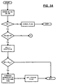
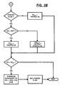
- control of the present invention is shown in flow chart format in Figs. 3A and 3B.
Abstract
Description
- This application is related to and claims priority from British Patent Applications No. 9828452.4, filed 12/24/98, and 9900777.5, filed 01/15/99, both assigned to EATON CORPORATION, the assignee of this application.
- The present invention relates to a control method/system for controlling downshifting in an at least partially automated mechanical transmission system. In particular, the present invention relates to the control of downshifting in a vehicular automated mechanical transmission system wherein the system senses operation of an engine brake and the vehicle service brakes (also called foot brakes) and will modify downshift points as a function thereof.
- Fully or partially automated mechanical transmission systems for vehicular use are known in the prior art, as may be seen by reference to U.S. Pats. No. 4,361,060; 4,648,290; 4,722,248; 4,850,236; 5,389,053; 5,487,004; 5,435,212 and 5,755,639. The use of engine brakes (also known as compression brakes, exhaust brakes or Jake brakes) and transmission controls utilizing same are known in the prior art, as may be seen by reference to U.S. Pats. No. 5,409,432 and 5,425,689.
- An object of the present invention is to provide a control for a vehicular automated mechanical transmission system which will sense the operator's manual operation of the engine brake and/or foot brake systems and will modify the transmission shift points as a function thereof. In particular, the transmission downshift shift points will be modified in a manner which will provide the vehicle operator with the level of engine braking perceived to be requested by his/her operation of the engine brake and/or foot brake control.
- This and other objects and advantages of the present invention will become apparent from a reading of the following description of the preferred embodiment taken in connection with the attached drawings.
-
- Fig. 1 is a schematic illustration, in block diagram formt, of an automated mechanical transmission system utilizing the control of the present invention.
- Fig. 2 is a schematic illustration, in graphical format, illustrating shift point profiles for the transmission system of Fig. 1 according to the present invention.
- Figs. 3A and 3B are schematic illustrations, in flow chart format, of the control of the present invention.
-
- An at least partially automated mechanical transmission system intended for vehicular use is schematically illustrated in Fig. 1. The automated transmission system 10 includes a fuel-controlled engine 12 (such as a well-known diesel engine or the like), a multiple-speed, change-
gear transmission 14, and a non-positive coupling 16 (such as a friction master clutch) drivingly interposed between the engine and theinput shaft 18 of the transmission. Thetransmission 14 may be of the compound type comprising a main transmission section connected in series with a splitter- and/or range-type auxiliary section. Transmissions of this type, especially as used with heavy-duty vehicles, typically have 9, 10, 12, 13, 16 or 18 forward speeds. Examples of such transmissions may be seen by reference to U.S. Pats. No. 5,390,561 and 5,737,978, the disclosures of which are incorporated herein by reference. - A
transmission output shaft 20 extends outwardly from thetransmission 14 and is drivingly connected with thevehicle drive axles 22, usually by means of a prop shaft 24. The illustratedmaster friction clutch 16 includes adriving portion 16A connected to the engine crankshaft/ flywheel and a drivenportion 16B coupled to thetransmission input shaft 18 and adapted to frictionally engage thedriving portion 16A. An upshift brake 26 (also known as an input shaft brake or inertia brake) may be used for selectively decelerating the rotational speed of theinput shaft 18 for more rapid upshifting, as is well known. Input shaft or upshift brakes are known in the prior art, as may be seen by reference to U.S. Pats. No. 5,655,407 and 5,713,445. - A microprocessor-based electronic control unit (or ECU) 28 is provided for receiving
input signals 30 and for processing same in accordance with predetermined logic rules to issuecommand output signals 32 to various system actuators and the like. Microprocessor-based controllers of this type are well known, and an example thereof may be seen by reference to U.S. Pats. No. 4,595,986 and 4,648,290. - System 10 includes a
rotational speed sensor 34 for sensing rotational speed of the engine and providing an output signal (ES) indicative thereof, arotational speed sensor 36 for sensing the rotational speed of theinput shaft 16 and providing an output signal (IS) indicative thereof, and arotational speed sensor 38 for sensing the rotational speed of theoutput shaft 20 and providing an output signal (OS) indicative thereof. Asensor 40 may be provided for sensing the displacement of the throttle pedal and providing an output signal (THL) indicative thereof. Ashift control console 42 may be provided for allowing the operator to select an operating mode of the transmission system and for providing an output signal (GRT) indicative thereof. - As is known, the rotational speed of the engine may be determined from the speed of the input shaft if the clutch is engaged and/or the speed of the output shaft and the engaged transmission ratio.
- Alternatively, for systems wherein at least some of the shifting is controlled by a
manual shift lever 43, a sensor may be provided for providing an input signal (SL) indicative of the position of the shift lever. Sensors of this basic type may be seen by reference to U.S. Pat. No. 5,743,143. - System 10 also includes
sensors - The
master clutch 16 may be controlled by aclutch pedal 48 or by aclutch actuator 50 responding to output signals from theECU 28. Alternatively, an actuator responsive to control output signals may be provided, which may be overridden by operation of the manual clutch pedal. Automated operation of a vehicular master clutch is known, as may be seen by reference to U.S. Pats. No. 4,081,065 and 5,630,773. Thetransmission 14 may include atransmission actuator 52, which responds to output signals from theECU 28 and/or which sends input signals to theECU 28 indicative of the selected position thereof. Shift mechanisms of this type, often of the so-called X-Y shifter type, are known in the prior art, as may be seen by reference to U.S. Pats. No. 5,305,240 and 5,219,391.Actuator 52 may shift the main and/or auxiliary section oftransmission 14. - Fueling of the engine is preferably controlled by an
electronic engine controller 54, which accepts command signals from and/or provides input signals to theECU 28. Preferably, theengine controller 54 will communicate with an industry standard data link DL which conforms to well-known industry protocols such as SAE J1922, SAE 1939 and/or ISO 11898. The ECU 28 may be incorporated within theengine controller 54. - The effectiveness of vehicle retardation provided by an engine or exhaust brake is determined in part by the speed of the engine and the engaged transmission ratio. Briefly, operation at the upper rotational speeds of the engine generally provides increased vehicle retardation, while changing gear ratio repeatedly will result in torque breaks in a mechanical transmission, which will significantly decrease the retardation effect of engine braking.
- The downshift control of the present invention to provide enhanced vehicle retardation in response to sensed actuation of the engine brake and/or engine and foot brake systems may be seen by reference to Fig. 2. Fig. 2 is a graphical representation of shift point profiles utilized to determine when shift commands should be issued by the
ECU 28 to theshift actuator 52.Solid line 60 is the default upshift profile, whilesolid line 62 is the default downshift profile. As is known, if the vehicle is operating to the right ofupshift profile 60, an upshift oftransmission 14 should be commanded, while if the vehicle is operating to the left ofdownshift profile 62, a downshift should be commanded. If the vehicle is operating in betweenprofiles - Upon sensing manual actuation of the
engine brake 46, the system will react to force an early downshift by shifting the downshift profile rightwardly (i.e., increasing the engine speed at which a downshift will be commanded, thereby increasing the speed of the engine upon completion of a downshift). In the example illustrated in Fig. 2, if operation of the engine brake EB is set and/or operation of the engine brake and operation of the foot brake system is set, the downshift profile will be shifted rightwardly, as indicated byshift profile 66.Shift profile 66 will result in an earlier downshift and a relatively elevated engine speed at completion of the forced downshift. By way of example, at lower throttle position values, if the default downshift value is about 950 RPM, the forced downshift value ofprofile 66 will be about 1300-1400 RPM. - If engine braking but not foot braking is set, upon forcing a downshift, the control will command a downshift to bring engine speed to about 1400-1700 RPM; if engine braking and foot braking are set, the control will command a downshift to bring engine speed to between about 1700-2000 RPM. Operating at such elevated engine speeds will result in enhanced engine brake effectiveness in retarding the speed of the vehicle.
- If engine braking but not foot braking is set and vehicle speed is above a given value (i.e., about 30 MPH), after a forced downshift (i.e., a downshift from profile 66), the downshift profile will return to the
default value 62 thereof. If engine braking but not foot braking is set and vehicle speed is below the set value (i.e., OS < REF), then the downshift profile is caused to assume aprofile value 64intermediate default profile 62 and the forceddownshift profile 66. By way of example, if at lower throttle positions thedefault profile 62 value is about 950 RPM and the forceddownshift profile 66 value is about 1300-1400 RPM, then the value onprofile 64 will be about 1100 RPM. - If engine braking and foot braking both are set, the forced
downshift profile 66 will remain effective. If the engine brake is activated, the system raises the downshift point to approximately 1300-1400 RPM (the value is two ratio steps down from the maximum engine speed). The downshift made under these conditions, if any, brings the engine speed to between 1400-1700 RPM, allowing the driver a moderate level of engine braking. - If the engine brake is pressed and the foot/service brake is pressed, or if the two are pressed together, then the system will raise the downshift point to approximately 1300-1400 RPM. The system will make a downshift, if necessary, to bring the engine speed to between 1700-2000 RPM to give a maximum level of engine braking. As the vehicle slows down, it will downshift again when it reaches the raised dsownshift point (1300-1400 RPM) and make a skip downshift to bring the engine speed up to approximately 2000 RPM.
- As long as the driver keeps his foot on the engine brake (he may release the foot brake if he wishes), the system will remain in this state. While in this mode, if the driver removes his foot from the foot brake, the system will remain in this mode. If the driver then reapplies the foot brake while maintaining the engine brake on, the system will make a downshift if possible (usually a single) to raise the engine speed as high as possible. This assists in maximizing engine brake performance when descending hills.
- In summary, there are two enhanced braking states, engine-brake-only and engine-brake-plus-foot-brake. Engine-brake-only gives moderate engine speeds and a moderate level of engine braking (single shifts, skips at lower vehicle speeds). Engine-brake-plus-foot-brake gives higher engine speeds for a maximum level of engine braking (skip shifts, though the first shift may be a single to get it into the 1700-2000-RPM range, for example, 1800-1900 RPM). The driver may switch between the two states very easily, for example, touching the foot brake while in engine-brake-only mode changes to engine-brake-plus-foot-brake. Also, if the driver is in engine-brake-plus-foot-brake mode (foot off foot brake) and briefly releases the engine brake, he will revert to engine-brake-only mode.
- The control of the present invention is shown in flow chart format in Figs. 3A and 3B.
- Accordingly, it may be seen that an improved control system/method for an at least partially automated mechanical transmission system in a vehicle having manually operated engine brake and foot brake systems is provided. The system modifies the engine speeds at which downshifts are commanded and responds to sensing operation of the foot brake system and/or the engine brake system to enhance the vehicle retardation effectiveness of the engine brake system.
- Although the present invention has been described with a certain degree of particularity, it is understood that the description of the preferred embodiment is by way of example only and that numerous changes to form and detail are possible without departing from the spirit and scope of the invention as hereinafter claimed.
Claims (11)
- A method for controlling automatic downshifting in a vehicular automated mechanical transmission system (10) for a vehicle equipped with a manually operated foot brake system and a manually operated engine brake system, said automated mechanical transmission system comprising a fuel-controlled engine (12), a multiple-speed mechanical transmission (14), and a controller (28) for receiving input signals (30) including one or more of signals indicative of engine speed (ES), foot brake system operation (FB), and engine brake system operation (EB, and to process said input signals in accordance with with logic rules to issue command output signals (32) to transmission system actuators including a transmission actuator (52) effective to shift said transmission, said method characterized by:(i) establishing a default value (62) for engine speed at which a downshift will be commanded;(ii) sensing for operation of said engine brake system (EB);(iii) if engine brake system operation is sensed, then increasing the value of engine speed at which downshifts will be commanded (ESD/S) to a first increased value (66) greater than said default value.
- The method of claim 1 further characterized by sensing operation of said foot brake system (FB?) and, after a downshift from said first increased value,(iv) causing the engine speed at which downshifts will be commanded to remain at said first increased value if operation of both the engine brake system and foot brake system are sensed.
- The method of claim 1 further characterized by sensing operation of said foot brake system (FB?) and, after a downshift from said first increased value,(v) causing the engine speed at which downshifts will be commanded to be decreased to a second increased value (64) if operation of the engine brake system but not the foot brake system is sensed and vehicle speed is less than a reference value (OS < REF), said second increased value (64) being greater than said default value but less than said first increased value (62 < 64 < 66).
- The method of claim 2 further characterized by sensing operation of said foot brake system (FB?) and, after a downshift from said first increased value,(v) causing the engine speed at which downshifts will be commanded to be decreased to a second increased value (64) if operation of the engine brake system but not the foot brake system is sensed and vehicle speed is less than a reference value (OS < REF), said second increased value (64) being greater than said default value but less than said first increased value (62 < 64 < 66).
- The method of claim 1 further characterized by sensing operation of said foot brake system (FB?) and, after a downshift from said first increased value,(vi) causing the engine speed at which downshifts will be commanded to return to said default value (62) if operation of the engine brake system but not the foot brake system is sensed and vehicle speed is greater than a reference value (OS > REF).
- The method of claim 2 further characterized by sensing operation of said foot brake system (FB?) and, after a downshift from said first increased value,(vi) causing the engine speed at which downshifts will be commanded to return to said default value (62) if operation of the engine brake system but not the foot brake system is sensed and vehicle speed is greater than a reference value (OS > REF).
- The method of claim 4 further characterized by sensing operation of said foot brake system (FB?) and, after a downshift from said first increased value,(vi) causing the engine speed at which downshifts will be commanded to return to said default value (62) if operation of the engine brake system but not the foot brake system is sensed and vehicle speed is greater than a reference value (OS > REF).
- The method of claim 1 further characterized by sensing operation of said foot brake system (FB?), and downshifts from said first increased value are to a target gear ratio (GRT) intended to result in a first target gear engine speed (ESTG) if operation of both the engine brake system and foot brake system are sensed and in a second target gear ratio, engine speed less than said first target gear engine speed, if operation of the engine brake system but not the foot brake system is sensed.
- The method of claim 2 further characterized by sensing operation of said foot brake system (FB?), and downshifts from said first increased value are to a target gear ratio (GRT) intended to result in a first target gear engine speed (ESTG) if operation of both the engine brake system and foot brake system are sensed and in a second target gear ratio engine speed less than said first target gear engine speed (ESTG 1 > ESTG2), if operation of the engine brake system but not the foot brake system is sensed.
- The method of claim 3 further characterized by sensing operation of said foot brake system (FB?), and downshifts from said first increased value are to a target gear ratio (GRT) intended to result in a first target gear engine speed (ESTG) if operation of both the engine brake system and foot brake system are sensed and in a second target gear ratio, engine speed less than said first target gear engine speed, if operation of the engine brake system but not the foot brake system is sensed.
- The method of claim 4 further characterized by sensing operation of said foot brake system (FB?), and downshifts from said first increased value are to a target gear ratio (GRT) intended to result in a first target gear engine speed (ESTG) if operation of both the engine brake system and foot brake system are sensed and in a second target gear ratio, engine speed less than said first target gear engine speed, if operation of the engine brake system but not the foot brake system is sensed.
Applications Claiming Priority (5)
| Application Number | Priority Date | Filing Date | Title |
|---|---|---|---|
| GBGB9828452.4A GB9828452D0 (en) | 1998-12-24 | 1998-12-24 | Automated transmission downshift control |
| GB9828452 | 1998-12-24 | ||
| GB9900777 | 1999-01-15 | ||
| GB9900777 | 1999-01-15 | ||
| US09/471,872 US6231474B1 (en) | 1998-12-24 | 1999-12-23 | Automated transmission downshift control |
Publications (3)
| Publication Number | Publication Date |
|---|---|
| EP1013497A2 true EP1013497A2 (en) | 2000-06-28 |
| EP1013497A3 EP1013497A3 (en) | 2001-01-03 |
| EP1013497B1 EP1013497B1 (en) | 2006-05-10 |
Family
ID=27269597
Family Applications (1)
| Application Number | Title | Priority Date | Filing Date |
|---|---|---|---|
| EP99124892A Expired - Lifetime EP1013497B1 (en) | 1998-12-24 | 1999-12-17 | Automated transmission downshift control |
Country Status (4)
| Country | Link |
|---|---|
| EP (1) | EP1013497B1 (en) |
| JP (1) | JP2000193085A (en) |
| CN (1) | CN1170700C (en) |
| BR (1) | BR9907350B1 (en) |
Cited By (2)
| Publication number | Priority date | Publication date | Assignee | Title |
|---|---|---|---|---|
| EP1674755A3 (en) * | 2004-12-27 | 2008-05-07 | Aisin Seiki Kabushiki Kaisha | Automatic shift control apparatus |
| US8744704B2 (en) | 2009-09-14 | 2014-06-03 | Scania Cv Ab | Method for determination of gearshift points |
Families Citing this family (4)
| Publication number | Priority date | Publication date | Assignee | Title |
|---|---|---|---|---|
| CN100509514C (en) * | 2005-05-17 | 2009-07-08 | 比亚迪股份有限公司 | Device and method for judging brake instancy |
| US7780567B2 (en) * | 2007-06-07 | 2010-08-24 | Gm Global Technology Operations, Inc. | Input brake assembly |
| JP6196905B2 (en) * | 2014-01-20 | 2017-09-13 | 日野自動車株式会社 | Vehicle shift control device |
| CN113124148B (en) * | 2021-04-20 | 2022-08-23 | 潍柴动力股份有限公司 | Gear shifting control method and device |
Citations (10)
| Publication number | Priority date | Publication date | Assignee | Title |
|---|---|---|---|---|
| US4361060A (en) | 1978-01-24 | 1982-11-30 | Smyth Robert Ralston | Mechanical automatic transmission |
| US4648290A (en) | 1984-07-23 | 1987-03-10 | Eaton Corporation | Semi-automatic mechanical transmission control |
| US4722248A (en) | 1986-04-11 | 1988-02-02 | Eaton Corporation | Transmission shift control system |
| US4850236A (en) | 1987-11-20 | 1989-07-25 | Eaton Corporation | Vehicle drive line shift control system and method |
| US5389053A (en) | 1993-07-21 | 1995-02-14 | Eaton Corporation | System and method for sliding clutch engagement under tooth butt or torque lock conditions |
| US5409432A (en) | 1993-08-10 | 1995-04-25 | Eaton Corporation | Control system/method for engine brake assisted shifting |
| US5425689A (en) | 1992-07-06 | 1995-06-20 | Eaton Corporation | Engine brake enhanced upshift control method/system |
| US5435212A (en) | 1992-10-30 | 1995-07-25 | Eaton Corporation | Semi-automatic shift implementation |
| US5487004A (en) | 1993-10-29 | 1996-01-23 | Eaton Corporation | Control system/method for automated mechanical transmission systems |
| US5755639A (en) | 1996-04-30 | 1998-05-26 | Eaton Corporation | Semi-automatic shift implementation with automatic splitter shifting |
Family Cites Families (9)
| Publication number | Priority date | Publication date | Assignee | Title |
|---|---|---|---|---|
| DE3139985A1 (en) * | 1981-07-15 | 1983-02-03 | Bosch Gmbh Robert | METHOD FOR CONTROLLING AUTOMATIC TRANSMISSIONS IN MOTOR VEHICLES |
| JPS61108019A (en) * | 1984-10-31 | 1986-05-26 | Shimadzu Corp | Reduction control system for vehicle |
| JPH065099B2 (en) * | 1985-07-08 | 1994-01-19 | 日産自動車株式会社 | Transmission control device |
| JPH0784149B2 (en) * | 1985-09-30 | 1995-09-13 | アイシン精機株式会社 | Control method of automatic transmission for vehicle with exhaust brake |
| EP0270708B1 (en) * | 1986-12-05 | 1990-08-29 | Eaton Corporation | Control and method for controlling amt system including manually operated engine compression brake |
| US5161432A (en) * | 1990-02-15 | 1992-11-10 | Jatco Corporation | Engine brake control system for automatic power transmission with variable response characteristics in shifting operational mode into engine braking range |
| US5105923A (en) * | 1990-09-27 | 1992-04-21 | Jatco Corporation | Engine braking control system for automotive automatic transmissions |
| JP2984405B2 (en) * | 1991-03-27 | 1999-11-29 | ジャトコ株式会社 | Transmission control device for automatic transmission |
| DE4120603C2 (en) * | 1991-06-21 | 1995-11-09 | Porsche Ag | Control device for an automatically shifting transmission of a motor vehicle |
-
1999
- 1999-12-17 EP EP99124892A patent/EP1013497B1/en not_active Expired - Lifetime
- 1999-12-22 BR BRPI9907350-1A patent/BR9907350B1/en not_active IP Right Cessation
- 1999-12-24 JP JP11368146A patent/JP2000193085A/en active Pending
- 1999-12-24 CN CNB99127783XA patent/CN1170700C/en not_active Expired - Lifetime
Patent Citations (10)
| Publication number | Priority date | Publication date | Assignee | Title |
|---|---|---|---|---|
| US4361060A (en) | 1978-01-24 | 1982-11-30 | Smyth Robert Ralston | Mechanical automatic transmission |
| US4648290A (en) | 1984-07-23 | 1987-03-10 | Eaton Corporation | Semi-automatic mechanical transmission control |
| US4722248A (en) | 1986-04-11 | 1988-02-02 | Eaton Corporation | Transmission shift control system |
| US4850236A (en) | 1987-11-20 | 1989-07-25 | Eaton Corporation | Vehicle drive line shift control system and method |
| US5425689A (en) | 1992-07-06 | 1995-06-20 | Eaton Corporation | Engine brake enhanced upshift control method/system |
| US5435212A (en) | 1992-10-30 | 1995-07-25 | Eaton Corporation | Semi-automatic shift implementation |
| US5389053A (en) | 1993-07-21 | 1995-02-14 | Eaton Corporation | System and method for sliding clutch engagement under tooth butt or torque lock conditions |
| US5409432A (en) | 1993-08-10 | 1995-04-25 | Eaton Corporation | Control system/method for engine brake assisted shifting |
| US5487004A (en) | 1993-10-29 | 1996-01-23 | Eaton Corporation | Control system/method for automated mechanical transmission systems |
| US5755639A (en) | 1996-04-30 | 1998-05-26 | Eaton Corporation | Semi-automatic shift implementation with automatic splitter shifting |
Cited By (2)
| Publication number | Priority date | Publication date | Assignee | Title |
|---|---|---|---|---|
| EP1674755A3 (en) * | 2004-12-27 | 2008-05-07 | Aisin Seiki Kabushiki Kaisha | Automatic shift control apparatus |
| US8744704B2 (en) | 2009-09-14 | 2014-06-03 | Scania Cv Ab | Method for determination of gearshift points |
Also Published As
| Publication number | Publication date |
|---|---|
| EP1013497B1 (en) | 2006-05-10 |
| CN1170700C (en) | 2004-10-13 |
| JP2000193085A (en) | 2000-07-14 |
| BR9907350A (en) | 2001-01-16 |
| BR9907350B1 (en) | 2010-11-16 |
| CN1270900A (en) | 2000-10-25 |
| EP1013497A3 (en) | 2001-01-03 |
Similar Documents
| Publication | Publication Date | Title |
|---|---|---|
| US5681242A (en) | Selectable enhanced creep control mode for automated clutch and vehicular automated mechanical transmission system utilizing same | |
| EP0702170B1 (en) | Clutch reengagement control | |
| US6149545A (en) | Automated transmission upshift control | |
| US6066071A (en) | Automated transmission downshift control | |
| US6113516A (en) | Adaptive automated transmission upshift control | |
| EP1070625B1 (en) | Starting and driveline shock protection control method and system | |
| EP1152172B1 (en) | Automated transmission upshift control | |
| EP0943838A1 (en) | Control system/method for input shaft retarder-assisted upshifts | |
| US6123644A (en) | Adaptive anti-hunt logic for automated transmission downshift control | |
| US6231474B1 (en) | Automated transmission downshift control | |
| EP1013497B1 (en) | Automated transmission downshift control | |
| EP1186792A1 (en) | Control to determine input shaft direction of rotation | |
| US6146310A (en) | Adaptive automated transmission downshift control | |
| EP1514041B1 (en) | Method of detecting false neutral in an automated transmission system | |
| EP1606529B1 (en) | System and method for controlling engagement of a clutch | |
| EP1186808B1 (en) | Shift control method for an automatic transmission | |
| EP0985856B1 (en) | Method/system for controlling upshifting in an automated mechanical transmission system | |
| KR20000048290A (en) | Automated transmission downshift control |
Legal Events
| Date | Code | Title | Description |
|---|---|---|---|
| PUAI | Public reference made under article 153(3) epc to a published international application that has entered the european phase |
Free format text: ORIGINAL CODE: 0009012 |
|
| AK | Designated contracting states |
Kind code of ref document: A2 Designated state(s): DE ES FR GB IT SE |
|
| AX | Request for extension of the european patent |
Free format text: AL;LT;LV;MK;RO;SI |
|
| PUAL | Search report despatched |
Free format text: ORIGINAL CODE: 0009013 |
|
| AK | Designated contracting states |
Kind code of ref document: A3 Designated state(s): AT BE CH CY DE DK ES FI FR GB GR IE IT LI LU MC NL PT SE |
|
| AX | Request for extension of the european patent |
Free format text: AL;LT;LV;MK;RO;SI |
|
| RIC1 | Information provided on ipc code assigned before grant |
Free format text: 7B 60K 41/08 A, 7B 60K 41/26 B, 7F 16H 61/02 B, 7F 16H 61/21 B, 7F 16H 103:02 Z |
|
| 17P | Request for examination filed |
Effective date: 20010504 |
|
| AKX | Designation fees paid |
Free format text: DE ES FR GB IT SE |
|
| 17Q | First examination report despatched |
Effective date: 20041215 |
|
| GRAP | Despatch of communication of intention to grant a patent |
Free format text: ORIGINAL CODE: EPIDOSNIGR1 |
|
| RIC1 | Information provided on ipc code assigned before grant |
Ipc: F16H 61/02 19900101ALI20051201BHEP Ipc: F16H 61/21 20000101AFI20051201BHEP |
|
| GRAS | Grant fee paid |
Free format text: ORIGINAL CODE: EPIDOSNIGR3 |
|
| GRAA | (expected) grant |
Free format text: ORIGINAL CODE: 0009210 |
|
| AK | Designated contracting states |
Kind code of ref document: B1 Designated state(s): DE ES FR GB IT SE |
|
| PG25 | Lapsed in a contracting state [announced via postgrant information from national office to epo] |
Ref country code: IT Free format text: LAPSE BECAUSE OF FAILURE TO SUBMIT A TRANSLATION OF THE DESCRIPTION OR TO PAY THE FEE WITHIN THE PRE;WARNING: LAPSES OF ITALIAN PATENTS WITH EFFECTIVE DATE BEFORE 2007 MAY HAVE OCCURRED AT ANY TIME BEFORE 2007. THE CORRECT EFFECTIVE DATE MAY BE DIFFERENT FROM THE ONE RECORDED.SCRIBED TIME-LIMIT Effective date: 20060510 |
|
| REG | Reference to a national code |
Ref country code: GB Ref legal event code: FG4D |
|
| REF | Corresponds to: |
Ref document number: 69931239 Country of ref document: DE Date of ref document: 20060614 Kind code of ref document: P |
|
| PG25 | Lapsed in a contracting state [announced via postgrant information from national office to epo] |
Ref country code: ES Free format text: LAPSE BECAUSE OF FAILURE TO SUBMIT A TRANSLATION OF THE DESCRIPTION OR TO PAY THE FEE WITHIN THE PRESCRIBED TIME-LIMIT Effective date: 20060821 |
|
| REG | Reference to a national code |
Ref country code: SE Ref legal event code: TRGR |
|
| PLBE | No opposition filed within time limit |
Free format text: ORIGINAL CODE: 0009261 |
|
| STAA | Information on the status of an ep patent application or granted ep patent |
Free format text: STATUS: NO OPPOSITION FILED WITHIN TIME LIMIT |
|
| 26N | No opposition filed |
Effective date: 20070213 |
|
| EN | Fr: translation not filed | ||
| PG25 | Lapsed in a contracting state [announced via postgrant information from national office to epo] |
Ref country code: FR Free format text: LAPSE BECAUSE OF FAILURE TO SUBMIT A TRANSLATION OF THE DESCRIPTION OR TO PAY THE FEE WITHIN THE PRESCRIBED TIME-LIMIT Effective date: 20070309 |
|
| PG25 | Lapsed in a contracting state [announced via postgrant information from national office to epo] |
Ref country code: FR Free format text: LAPSE BECAUSE OF FAILURE TO SUBMIT A TRANSLATION OF THE DESCRIPTION OR TO PAY THE FEE WITHIN THE PRESCRIBED TIME-LIMIT Effective date: 20060510 |
|
| REG | Reference to a national code |
Ref country code: GB Ref legal event code: 732E Free format text: REGISTERED BETWEEN 20181115 AND 20181130 |
|
| PGFP | Annual fee paid to national office [announced via postgrant information from national office to epo] |
Ref country code: DE Payment date: 20181126 Year of fee payment: 20 Ref country code: SE Payment date: 20181126 Year of fee payment: 20 |
|
| PGFP | Annual fee paid to national office [announced via postgrant information from national office to epo] |
Ref country code: GB Payment date: 20181127 Year of fee payment: 20 |
|
| REG | Reference to a national code |
Ref country code: DE Ref legal event code: R071 Ref document number: 69931239 Country of ref document: DE |
|
| REG | Reference to a national code |
Ref country code: GB Ref legal event code: PE20 Expiry date: 20191216 |
|
| REG | Reference to a national code |
Ref country code: SE Ref legal event code: EUG |
|
| PG25 | Lapsed in a contracting state [announced via postgrant information from national office to epo] |
Ref country code: GB Free format text: LAPSE BECAUSE OF EXPIRATION OF PROTECTION Effective date: 20191216 |
|
| P01 | Opt-out of the competence of the unified patent court (upc) registered |
Effective date: 20230521 |