EP1009483B1 - Treatment device for topical photodynamic therapy - Google Patents
Treatment device for topical photodynamic therapy Download PDFInfo
- Publication number
- EP1009483B1 EP1009483B1 EP98945776A EP98945776A EP1009483B1 EP 1009483 B1 EP1009483 B1 EP 1009483B1 EP 98945776 A EP98945776 A EP 98945776A EP 98945776 A EP98945776 A EP 98945776A EP 1009483 B1 EP1009483 B1 EP 1009483B1
- Authority
- EP
- European Patent Office
- Prior art keywords
- light emitting
- treatment device
- light
- treatment
- disposed
- Prior art date
- Legal status (The legal status is an assumption and is not a legal conclusion. Google has not performed a legal analysis and makes no representation as to the accuracy of the status listed.)
- Expired - Lifetime
Links
Images


Classifications
-
- A—HUMAN NECESSITIES
- A61—MEDICAL OR VETERINARY SCIENCE; HYGIENE
- A61N—ELECTROTHERAPY; MAGNETOTHERAPY; RADIATION THERAPY; ULTRASOUND THERAPY
- A61N5/00—Radiation therapy
- A61N5/06—Radiation therapy using light
- A61N5/0601—Apparatus for use inside the body
-
- A—HUMAN NECESSITIES
- A61—MEDICAL OR VETERINARY SCIENCE; HYGIENE
- A61N—ELECTROTHERAPY; MAGNETOTHERAPY; RADIATION THERAPY; ULTRASOUND THERAPY
- A61N5/00—Radiation therapy
- A61N5/06—Radiation therapy using light
- A61N5/0613—Apparatus adapted for a specific treatment
- A61N5/062—Photodynamic therapy, i.e. excitation of an agent
-
- A—HUMAN NECESSITIES
- A61—MEDICAL OR VETERINARY SCIENCE; HYGIENE
- A61B—DIAGNOSIS; SURGERY; IDENTIFICATION
- A61B17/00—Surgical instruments, devices or methods, e.g. tourniquets
- A61B2017/00017—Electrical control of surgical instruments
- A61B2017/00022—Sensing or detecting at the treatment site
- A61B2017/00057—Light
-
- A—HUMAN NECESSITIES
- A61—MEDICAL OR VETERINARY SCIENCE; HYGIENE
- A61N—ELECTROTHERAPY; MAGNETOTHERAPY; RADIATION THERAPY; ULTRASOUND THERAPY
- A61N5/00—Radiation therapy
- A61N2005/002—Cooling systems
- A61N2005/005—Cooling systems for cooling the radiator
-
- A—HUMAN NECESSITIES
- A61—MEDICAL OR VETERINARY SCIENCE; HYGIENE
- A61N—ELECTROTHERAPY; MAGNETOTHERAPY; RADIATION THERAPY; ULTRASOUND THERAPY
- A61N5/00—Radiation therapy
- A61N2005/002—Cooling systems
- A61N2005/007—Cooling systems for cooling the patient
-
- A—HUMAN NECESSITIES
- A61—MEDICAL OR VETERINARY SCIENCE; HYGIENE
- A61N—ELECTROTHERAPY; MAGNETOTHERAPY; RADIATION THERAPY; ULTRASOUND THERAPY
- A61N5/00—Radiation therapy
- A61N5/06—Radiation therapy using light
- A61N5/0601—Apparatus for use inside the body
- A61N5/0603—Apparatus for use inside the body for treatment of body cavities
- A61N2005/0606—Mouth
-
- A—HUMAN NECESSITIES
- A61—MEDICAL OR VETERINARY SCIENCE; HYGIENE
- A61N—ELECTROTHERAPY; MAGNETOTHERAPY; RADIATION THERAPY; ULTRASOUND THERAPY
- A61N5/00—Radiation therapy
- A61N5/06—Radiation therapy using light
- A61N2005/0635—Radiation therapy using light characterised by the body area to be irradiated
- A61N2005/0643—Applicators, probes irradiating specific body areas in close proximity
- A61N2005/0645—Applicators worn by the patient
-
- A—HUMAN NECESSITIES
- A61—MEDICAL OR VETERINARY SCIENCE; HYGIENE
- A61N—ELECTROTHERAPY; MAGNETOTHERAPY; RADIATION THERAPY; ULTRASOUND THERAPY
- A61N5/00—Radiation therapy
- A61N5/06—Radiation therapy using light
- A61N2005/065—Light sources therefor
- A61N2005/0651—Diodes
- A61N2005/0652—Arrays of diodes
Definitions
- the invention relates to a medical device for photodynamic therapy (PDT). More specifically, the invention relates to a generally flexible or rigid conforming patch or pad and a shaped article such as a mouthpiece which provide light sources for topical PDT.
- PDT photodynamic therapy
- the present invention advantageously uses light energy to treat or detect pathologies of living tissue, including cancer and microbiological pathogens.
- the present invention may be used in combination with photosensitizing agents.
- United States Patent No. 4,822,335, entitled, Apparatus For Treatment Of Cancer With Photodiode purportedly discloses an apparatus for the treatment of a cancerous lesion part by irradiating a light energy from a light source to the cancerous lesion part having absorbed and accumulated in advance therein a photosensitive substance with an affinity for tumors.
- the light source comprises a first diode adapted to excite the photosensitive substance from the ground state to a singlet state of higher energy level and a second photodiode adapted to excite an energy level of the photosensitive substance which has transited from the singlet state to a triplet state to a still higher energy level.
- United States Patent No. 5,358,503 entitled, Photo-Thermal Therapeutic Device and Method purportedly discloses an apparatus for simultaneous or selective treatment of an area of the skin and adjacent subcutaneous structure of a patient utilizing photo energy and therapeutic heat, which includes a plurality of juxtaposed diodes.
- Each diode has a longitudinal axis and is capable of projecting a non-coherent cone of light which overlaps the cone of light from each juxtaposed diode so that the light completely covers the treatment area.
- a pad or appliance holds the diodes in juxtaposed position with each other.
- United States Patent No. 5,611,793, entitled, Laser Treatment purportedly discloses a method of disinfecting or sterilizing tissues of the oral cavity or a wound or lesion in the oral cavity.
- the method includes applying a photosensitising compound to the tissue and irradiating with laser light at a wavelength absorbed by the photosensitising compound.
- WO 97/04836 to Dusa Pharmaceuticals Inc. discloses a light emitting patch for PDT comprising a hydrogel layer providing optical coupling between light emitting members and a skin surface and providing a medium through which photopharmaceuticals may be dispersed.
- US 5616140 to Prescott, M discloses a light emitting treatment device comprising an array of light emitting members mounted on a flexible circuit board within a flexible housing. Each light emitting member has an output of around 2.6 mW and a heat sink is provided in the housing.
- US 5445608 to Chen et al. discloses a light emitting implantable probe.
- the probe may be flexible and comprises an array of light emitting members connected to a central bar and enclosed in a polymer material.
- the central bar may be used to disperse heat.
- the invention relates to a PDT treatment device which is configured to deliver light energy to a treatment site from a plurality of light emitting members disposed in the device.
- a light emitting treatment device characterised by a flexible substrate element comprising a gel material and adapted to be used in association with a treatment field; one or more light emitting members disposed within the substrate element, said one or more light emitting members providing a light dosage rate to the treatment field at a value between about 0 mW/cm 2 to about 150 mW/cm 2 ; a heat dissipating layer for transferring heat generated by the one or more light emitting members away from the treatment field; and an outer layer disposed upon the substrate element for restricting the area of the treatment field exposed to light from the treatment device.
- the treatment device is flexible and is used for wound treatment and biostimulation.
- the treatment device with light emitting members operates at wavelengths ranging from about 450nm to about 850nm; a dosage rate ranging from about 0 mW/cm 2 to about 150 mW/cm 2 ; and a light dose ranging from 0 to 300 J/cm 2 .
- the treatment device may have surface monitor capabilities which include isotropic or anisotropic light detectors or photodetectors.
- the light detectors may be used in combination with a controller to automatically monitor light dosage, light power and dosage rate.
- a surface-conforming covering such as a light-diffusing pad and gel liner contain an integrated array of vertical cavity surface emitting lasers (VCSEL) as a light emitting source for topical PDT treatment.
- VCSEL vertical cavity surface emitting lasers
- a shaped article is configured to direct energy and is used for PDT treatment.
- One embodiment of the shaped article includes a mouthpiece for covering and treating a patient's gumline.
- Another embodiment includes a shaped article for treatment of the roof of a mouth.
- an embodiment of the invention relates to a light emitting treatment device including a shell and liner.
- the liner is at least partially disposed in the shell.
- One or more light emitting members are disposed in at least one of the liner or the shell.
- the shell, liner material and light emitting members form an assembly.
- the light emitting members are configured to emit energy from the assembly for photodynamic therapy of a body surface.
- the shell and liner may be made of a polymeric material.
- the shell or the liner may be made of a gel.
- the shell and the liner may be configured in a substantially integral structure.
- the treatment device is substantially flexible and may conform to a body surface.
- the light emitting members may be disposed in a substantially uniform array.
- the light emitting members may be configured to emit energy in a substantially uniform pattern.
- the light emitting members may be configured in a light diffusing layer.
- the light emitting treatment device may further include a heat dissipating layer, a layer of gold or gold alloy, or a layer of adhesive disposed on at least one surface of the shell or liner.
- the invention also relates to a light emitting treatment device including a shell made of a polymeric material and a liner made of a polymeric material including a gel.
- the liner is at least partially disposed in the shell.
- One or more light emitting members are disposed in an array in at least one of the liner or the shell.
- the shell, liner material and the light emitting members form an assembly.
- the light emitting members are configured to emit energy from the assembly in a substantially uniform pattern for photodynamic therapy.
- a heat dissipating layer is associated with the assembly.
- a layer of gold material is associated with an outside surface of the assembly.
- the invention also relates to a light emitting device including a shaped member.
- the shaped member is configured to be juxtaposed one or more body surfaces in a mouth.
- One or more light emitting members are disposed in the shaped member and are configured to emit energy to the one or more body surfaces for photodynamic therapy.
- the light emitting device may further include a remote light source operatively coupled to the shaped member via at least one of a fiber optic element, a plurality of internally embedded filaments, or one or more VCSELs, or combinations thereof.
- the shaped member may include a gel having light diffusing characteristics.
- the shaped member may be configured to treat a gum line for a disease.
- the one or more light emitting members may be embedded in the shaped member.
- the shaped member may be made of a polymer.
- the shaped member may further include a control operatively coupled to the shaped member to provide a range of intensity or selective operation of the emitted energy. The control may be used to operate the e
- a method of forming a light emitting treatment device including: forming a shell; forming a liner; disposing one or more light emitting members in the liner material; and disposing the liner at least partially in the shell.
- the shell, liner material and the light emitting members form an assembly.
- the light emitting members are configured to emit energy at a treatment site.
- a product made from the method of forming a light emitting treatment patch including: forming a member; and disposing one or more light emitting members in the member.
- the member and the one or more light emitting members form an assembly and the light emitting members are configured to emit energy at a treatment site for photodynamic therapy.
- a method of using a light emitting treatment device including: identifying an area of treatment on a body surface; applying a surface of a light emitting treatment device to a body surface or tissue.
- the light emitting treatment device having a liner and one or more light emitting members disposed in the liner.
- the liner and the light emitting members form an assembly.
- the light emitting members are configured to emit energy at a treatment site; activating a light transmitting source for a period of time such that the one or more light emitting members emit energy at the area of treatment for photodynamic therapy.
- the method may further include injecting a drug through the treatment device into the body.
- a product made from the process of forming a light emitting treatment device including; forming a mold; pouring a material into a recess defined by the mold, the material being configured in a substantially viscous liquid state; disposing one or more filaments in the mold prior to adding the material or embedding the one or more filaments within the material after it has been poured into the recess defined by the mold and curing or drying the material such that the material and the one or more filaments form a treatment device.
- the process may further include curing the material at an ambient temperature or at an elevated temperature.
- the invention also relates to a light emitting treatment device including a member having a thickness.
- the member is configured to conform to one or more body surfaces.
- One or more light emitting members are disposed in the member.
- the member and the one or more light emitting members form an assembly.
- the one or more light emitting members are configured to emit energy from the assembly for photodynamic therapy of the one or more body surfaces.
- the member may include one or more light detectors configured to provide surface monitoring.
- the light emitting treatment device may provide light wavelengths ranging from about 450nm to about 850nm; a light dosage rate ranging from about 0 mW/cm 2 to about 150 mW/cm 2 ; and a light dose ranging from 0 J/cm 2 to about 300 J/cm 2 .
- a treatment device 10, 20, 30 such as a patch, pad or shaped article is used to conform to one or more body surface characteristics and to treat the surface or tissue with PDT.
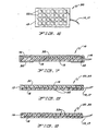
- Fig. 1 illustrates a treatment device 10 which has a plurality of radially diverging optical filaments and provides light-emitting and light diffusing characteristics.
- the treatment device 10 is used to treat an area of skin or exposed (or exposable) tissue with topical or surface exposure of PDT including generally uniform intensity light energy for long periods.
- Fig. 2 illustrates another embodiment of a treatment device 10 having a serpentine optical filament 12.
- Fig. 3 illustrates a cross-section of a treatment device 10 constructed of a shell 16 having a recessed area, a liner 18 formed in the recessed area, and an optical filament 12 embedded therein.
- the liner 18 has an exposed surface 20 on the bottom or skin-facing side. Together, the shell 16 and liner 18 define the shape and consistency of the treatment device 10 and form an integral or unitary structure.
- a suitable material for the shell 16 and liner 18 is silicone into which one or more optical or light-transmitting filaments 12 may be imbedded.
- the silicone material generally diffuses the light transmitted from the filaments 12 uniformly over an area of the body being treated.
- the shell 16 is preferably made of a cured liquid silicone rubber material such as dimethylsilicone which is sufficiently rigid to support and retain the liner material 18.
- the shell 16 is preferably made of a highly flexible, compressible, and deformable material having a durometer rating of approximately 20A (Shore units) or less; a tensile strength of about 450 psi minimum; elongation of about 650% minimum; and a tear strength of about 70 ppi minimum.
- One suitable material is LSR-10 which is liquid silicone rubber available under Product Identification No. 40023 from Applied Silicone Corporation of Ventura, California.
- the liner 18 is preferably made of a generally high strength and firm silicone gel composition which is inherently tacky to silicone rubber or skin.
- the liner 18 has a peel strength of approximately 0.5 ppi (lb./in.) or less from a stainless steel surface; and is hydrophobic and may be cleaned in water and reused without a substantial reduction in its intrinsic tackiness.
- One suitable material is a silicone gel material that is available under Product Identification No. 40022 from Applied Silicone Corporation of Ventura, California. Both the shell 16 and liner 18 generally appear substantially indistinguishable to the ordinary view of the patient.
- the shell 16 and liner 18 are generally clear and provide a sufficient texture or internal turbidity for suitable light-diffusing characteristics.
- One or more optical filaments 12 may be incorporated in the treatment device 10.
- the filaments 12 may be formed integral with or operatively connected to an optical fiber 14 and coupled with a remote light source (not shown).
- the filaments 12 are disposed in a suitable array which uniformly and efficiently disperses the light energy throughout the operative area of the treatment device 10.
- the array pattern may include radiating spokes or a serpentine configurations as shown in Figures 1-2 or other variations and combinations thereof.
- the shell 16 is first molded and the liner 18 is then poured, while in a highly viscous liquid or syrup-like state, into the recess defined by the shell 16.
- the filaments 12 may be disposed in the shell 16 prior to adding the liner material 18, or the filaments 12 may be embedded in the liner material 18 after the liquid material has been poured into the recess or during the initial stages of the curing process.
- the liner material 18 is then allowed to cure or dry. The drying or curing process can occur at ambient temperatures or may be assisted by the application of heat. In general, relatively little surface boundary distinction occurs between the filaments 12 and liner 18. Once cured or dried, the liner 18 bonds securely with the shell 16 and the filaments 12 to form a unitary or integral treatment device 10.
- Exposed surface 20 is generally highly tacky to skin and to the opposing surface 22 of the shell 16. If the exposed surface 20 remains in contact with the opposing surface of the shell 22 for an extended period of time, for example, if the treatment device 10 is wrapped circumferentially around an area being treated such as a finger or arm of the patient and adhered to itself, the liner 18 will not permanently bond with the shell 16. Thus, the liner 18 will releasably adhere to the overlapped regions of the shell 16 and the exposed surface 20 is not left behind on the shell 16 when the two surfaces 20, 22 are peeled apart.
- the shell 16 advantageously acts as a cohesive carrier of the liner material and as an attachable but releasable anchoring substrate for the liner 18.
- the treatment device 10 Due to the generally low shear or peel force properties of the liner 18 when in contact with the "reverse" side of the shell 16, the treatment device 10 advantageously exhibits a self-limidng wrapping characteristic.
- the treatment device 10 cannot be wrapped too tightly or it will naturally unpeel or unwrap itself, thereby preventing inadvertent constriction of blood circulation.
- the treatment device 10 advantageously remains in place when properly sized for an area of treatment and correct tension is used on a patient.
- the treatment device 10 advantageously conforms and, if necessary, stretches slightly to contact and cover a desired area for PDT.
- the treatment device 10 self-adheres to the area contacted by liner 18, and uniformly distributes light energy within the area being treated.
- the treatment device 10 is generally easily removed from the skin or tissue of the patient without discomfort or adverse affects on the tissue.
- a hypodermic syringe may be used to inject a therapeutic agent or marker through the treatment device 10 without removal or lifting during treatment.
- a portion of the treatment device 10 may be peeled away to expose the skin or tissue; to apply other topical medications; or to clean the tissue without removal of the remainder of the treatment device 10.
- Fig. 4 illustrates a plurality of array tiles 22 made of VCSELs arrayed in a treatment device 20 which is coupled to an independent power supply 19.
- a plurality of array tiles 22 made of VCSELs or light emitting diodes (LEDs) are disposed in an array or pattern and adhered to or mounted within a substrate 13 to form a treatment device 20.
- the treatment device 20 is operatively coupled to an adjustable, self-contained power source 19 such as battery using a conventional wire 17 or cable.
- the array tiles 22 and VCSELs or LEDs may be wired in series, parallel, or combinations of series and parallel using suitable patterns among adjacent rows or via a peripheral scheme.
- the treatment devices 10, 20, 30, 40 may have one or more surface monitor members 21 such as isotropic or anisotropic light detectors or photodetectors.
- the surface monitor members 21 may be used in combination with a controller to automatically monitor and control characteristics such as light wavelength (nm), light dosage (joules/cm 2 ), and light dosage rate (mW/cm 2 ).
- Fig. 5 illustrates a cross-sectional view of an embodiment of a treatment device 20 with an intermediate layer of array tiles 22 made of VCSELs disposed between a heat dissipating layer 29 and a light-diffusing layer 28.
- the light-diffusing layer 28 is preferably made of a silicone rubber material
- the heat-dissipating layer 29 is preferably made of a material configured to absorb or disperse heat generated by the array tiles 22 made of VSCELs 22.
- the VCSELs may be disposed in close proximity to one another, or spaced apart to facilitate flexing of the substrate 13.
- An embodiment of the substrate 13 preferably has dimensions of about 3.0 cm by 1.2 cm and includes 0.3 cm x .3 cm array tiles 22 made of VCSELs.
- the array tile 22 made of VCSELs may be any size, shape, or wavelength suitable for a variety of treatment applications.
- the number of VCSELs per array 22 may be selectively determined and will vary depending upon factors including the required light output (in mW/cm 2 ).
- the VCSELs are separated or spaced-apart from the tissue surface by a predetermined distance that is dependent upon factors including the incident light energy necessary for treatment, beam divergence, and the thickness or opacity of the light-diffusing layer 28. The separation may be approximately 1-2 mm.
- the array may be sufficiently flexible or malleable to conform to a variety of body shapes or parts such as the tongue, palate, or cheek, as well as normally exposed skin areas having complex or irregular curvatures or tight curves, such as a patient's arm or leg, finger or toe, heel, wrist, elbow.
- Fig. 6 illustrates a treatment device 30 having a plurality of array tiles 22 made of VCSELs.
- Fig. 7 illustrates an embodiment of the treatment device 10 with a layer 32 of material such as gold is disposed on one or more surfaces to contain the PDT to a certain area.
- the layer may be added at the time of treatment depending on the treatment area desired.
- Fig. 8 illustrates an embodiment of the treatment device 20, 30 of Figures 4 and 6.
- An embodiment of a substrate 13 is illustrated that is made of a shell 16 without a recess and a liner 18 formed over the array tiles 22 made of VCSELs and the shell 16.
- the treatment devices 10, 20, 30 may be made of a substrate 13 formed of one or more materials in a mold.
- a layer 32 of material such as gold is shown disposed on one surface to contain the PDT to a certain area.
- Fig. 9 illustrates another embodiment of the light emitting treatment device 20, 30.
- Fig. 10 illustrates a treatment device 10, 20, 30 disposed on a body surface along with an associated energy source and controller 60.
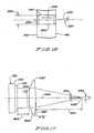
- Fig. 11 is a shaped device 40 that is shaped in the form of a mouthpiece 42 and includes energy emitting members 44.
- One embodiment of the shaped device 40 is in the form a mouthpiece which may be applied over the teeth and gums of a patient for the treatment of cancer.
- the shaped device 40 may be formed of silicone rubber or a similar light-diffusing material that will conform to a surface area to be treated using PDT.
- the shaped device 40 is operatively coupled to a remote light source using a fiber optic element or a plurality of internally embedded filaments.
- the shaped device may itself contain one or more VCSELs disposed in a array tile or pattern and is operatively coupled to a remote power supply.
- Fig. 12 illustrates the shaped device 40 disposed in a mouth of a patient.
- Fig. 13 illustrates another embodiment of the shaped device 50 that is in the form a mouthpiece 52.
- the mouthpiece 52 includes energy emitting members 54 that are used for PDT of the roof of the mouth.
- Fig. 14 illustrates the mouthpiece 50 of Figure 13 taken along the line of 14-14.
- Fig. 15 illustrates an array of laser diode elements that are used for a light emission and transmission system for PDT as an example of a remote light source.
- a monolithic 20x20 array 120 made of a plurality of laser diode elements 100 has front and rear surfaces 140, 160 that are operatively coupled to a thermal sink 180 for carrying excess heat 200 from the rear surface 160 of the array 120.
- Fig. 16 illustrates a laser diode element of the type disposed in the array 120 of Figure 15.
- Each laser diode element 100 preferably includes a mirror surface 220, a gain medium 240, and an output coupler 260. Energy in the form of a suitable electrically current 300 is input to the gain medium 240 and converted to laser light 320 and emitted from the output coupler 260 substantially normal to the front surface 140.
- Each laser diode element 100 is nominally cylindrical in shape; approximately 10 microns in diameter 280; and spaced a distance of approximately 100 microns in uniform relationship to adjacent laser diode elements 10.
- the laser light from each laser diode element 100 has a beam divergence half angle 340 of approximately 3°, and an output power in the range of approximately 0.1 to 5 milliwatts.
- the aggregate wavefront 360 of the laser diode elements 100 is incoherent with respect to phase, but is substantially plane parallel in the direction of propagation of the optical axis 400, thus impinging upon the lens system 420 as a conjugate in a manner substantially consistent with a beam emanating from a source at an infinite distance.
- Lens system 420 shares the same optical axis 400 as the array 120 and is separated from the array 12 by a distance 440 and separated from the focal point 520 by a distance 500.
- the lens system 420 has front and rear refractive surfaces 460, 480, respectively, defined by the refractive medium 470.
- the curvatures of the refractive surfaces 460, 480 and the focal distance 500 are optimally selected to condense or converge the aggregate wavefront 360 to a minimal focal area 520 at the "launch face" of the primary optical fiber 600, and optimally selected to meet the numerical aperture requirements of that primary optical fiber 600.
- the focused beam area will underfill an optical fiber of approximately 400 micron core size 640.
- the primary optical fiber 600 transmits the focused light energy to a light delivery mechanism (not shown), which consists at least of a disposable optical fiber operatively connected to a beam-directing instrument suitable for the specific treatment modality of application.
- a light delivery mechanism (not shown), which consists at least of a disposable optical fiber operatively connected to a beam-directing instrument suitable for the specific treatment modality of application.
- Fig. 17 illustrates an array of laser diode elements, lens system, and primary optical fiber utilised to emit and transmit laser light energy for PDT as an example of a remote light source.
- the light delivery mechanism is provided to the medical professional in a sterile form, and is removed from its packaging in preparation of a PDT session, and coupled prior to treatment to the primary optical fiber 600 proximate to its enclosure or housing (not shown) using a suitable focusing or butt coupling.
Abstract
Description
- The invention relates to a medical device for photodynamic therapy (PDT). More specifically, the invention relates to a generally flexible or rigid conforming patch or pad and a shaped article such as a mouthpiece which provide light sources for topical PDT. The present invention advantageously uses light energy to treat or detect pathologies of living tissue, including cancer and microbiological pathogens. The present invention may be used in combination with photosensitizing agents.
- United States Patent No. 4,822,335, entitled, Apparatus For Treatment Of Cancer With Photodiode, purportedly discloses an apparatus for the treatment of a cancerous lesion part by irradiating a light energy from a light source to the cancerous lesion part having absorbed and accumulated in advance therein a photosensitive substance with an affinity for tumors. The light source comprises a first diode adapted to excite the photosensitive substance from the ground state to a singlet state of higher energy level and a second photodiode adapted to excite an energy level of the photosensitive substance which has transited from the singlet state to a triplet state to a still higher energy level.
- United States Patent No. 5,358,503, entitled, Photo-Thermal Therapeutic Device and Method, purportedly discloses an apparatus for simultaneous or selective treatment of an area of the skin and adjacent subcutaneous structure of a patient utilizing photo energy and therapeutic heat, which includes a plurality of juxtaposed diodes. Each diode has a longitudinal axis and is capable of projecting a non-coherent cone of light which overlaps the cone of light from each juxtaposed diode so that the light completely covers the treatment area. A pad or appliance holds the diodes in juxtaposed position with each other.
- United States Patent No. 5,611,793, entitled, Laser Treatment, purportedly discloses a method of disinfecting or sterilizing tissues of the oral cavity or a wound or lesion in the oral cavity. The method includes applying a photosensitising compound to the tissue and irradiating with laser light at a wavelength absorbed by the photosensitising compound.
- WO 97/04836 to Dusa Pharmaceuticals Inc., discloses a light emitting patch for PDT comprising a hydrogel layer providing optical coupling between light emitting members and a skin surface and providing a medium through which photopharmaceuticals may be dispersed.
- US 5616140 to Prescott, M discloses a light emitting treatment device comprising an array of light emitting members mounted on a flexible circuit board within a flexible housing. Each light emitting member has an output of around 2.6 mW and a heat sink is provided in the housing.
- US 5445608 to Chen et al. discloses a light emitting implantable probe. The probe may be flexible and comprises an array of light emitting members connected to a central bar and enclosed in a polymer material. The central bar may be used to disperse heat.
- The invention relates to a PDT treatment device which is configured to deliver light energy to a treatment site from a plurality of light emitting members disposed in the device.
- According to an aspect of the present invention, there is provided a light emitting treatment device characterised by a flexible substrate element comprising a gel material and adapted to be used in association with a treatment field; one or more light emitting members disposed within the substrate element, said one or more light emitting members providing a light dosage rate to the treatment field at a value between about 0 mW/cm2 to about 150 mW/cm2; a heat dissipating layer for transferring heat generated by the one or more light emitting members away from the treatment field; and an outer layer disposed upon the substrate element for restricting the area of the treatment field exposed to light from the treatment device.
- The treatment device is flexible and is used for wound treatment and biostimulation. The treatment device with light emitting members operates at wavelengths ranging from about 450nm to about 850nm; a dosage rate ranging from about 0 mW/cm2 to about 150 mW/cm2; and a light dose ranging from 0 to 300 J/cm2. The treatment device may have surface monitor capabilities which include isotropic or anisotropic light detectors or photodetectors. The light detectors may be used in combination with a controller to automatically monitor light dosage, light power and dosage rate.
- In a preferred embodiment, a surface-conforming covering such as a light-diffusing pad and gel liner contain an integrated array of vertical cavity surface emitting lasers (VCSEL) as a light emitting source for topical PDT treatment.
- In another embodiment, a shaped article is configured to direct energy and is used for PDT treatment. One embodiment of the shaped article includes a mouthpiece for covering and treating a patient's gumline. Another embodiment includes a shaped article for treatment of the roof of a mouth.
- In sum, an embodiment of the invention relates to a light emitting treatment device including a shell and liner. The liner is at least partially disposed in the shell. One or more light emitting members are disposed in at least one of the liner or the shell. The shell, liner material and light emitting members form an assembly. The light emitting members are configured to emit energy from the assembly for photodynamic therapy of a body surface. The shell and liner may be made of a polymeric material. The shell or the liner may be made of a gel. The shell and the liner may be configured in a substantially integral structure. The treatment device is substantially flexible and may conform to a body surface. The light emitting members may be disposed in a substantially uniform array. The light emitting members may be configured to emit energy in a substantially uniform pattern. The light emitting members may be configured in a light diffusing layer. The light emitting treatment device may further include a heat dissipating layer, a layer of gold or gold alloy, or a layer of adhesive disposed on at least one surface of the shell or liner.
- The invention also relates to a light emitting treatment device including a shell made of a polymeric material and a liner made of a polymeric material including a gel. The liner is at least partially disposed in the shell. One or more light emitting members are disposed in an array in at least one of the liner or the shell. The shell, liner material and the light emitting members form an assembly. The light emitting members are configured to emit energy from the assembly in a substantially uniform pattern for photodynamic therapy. A heat dissipating layer is associated with the assembly. A layer of gold material is associated with an outside surface of the assembly.
- The invention also relates to a light emitting device including a shaped member. The shaped member is configured to be juxtaposed one or more body surfaces in a mouth. One or more light emitting members are disposed in the shaped member and are configured to emit energy to the one or more body surfaces for photodynamic therapy. The light emitting device may further include a remote light source operatively coupled to the shaped member via at least one of a fiber optic element, a plurality of internally embedded filaments, or one or more VCSELs, or combinations thereof. The shaped member may include a gel having light diffusing characteristics. The shaped member may be configured to treat a gum line for a disease. The one or more light emitting members may be embedded in the shaped member. The shaped member may be made of a polymer. The shaped member may further include a control operatively coupled to the shaped member to provide a range of intensity or selective operation of the emitted energy. The control may be used to operate the emitted energy in selected pattern or for selective periods of time.
- A method of forming a light emitting treatment device is disclosed, including: forming a shell; forming a liner; disposing one or more light emitting members in the liner material; and disposing the liner at least partially in the shell. The shell, liner material and the light emitting members form an assembly. The light emitting members are configured to emit energy at a treatment site.
- A product made from the method of forming a light emitting treatment patch is disclosed, including: forming a member; and disposing one or more light emitting members in the member. The member and the one or more light emitting members form an assembly and the light emitting members are configured to emit energy at a treatment site for photodynamic therapy.
- A method of using a light emitting treatment device is disclosed, including: identifying an area of treatment on a body surface; applying a surface of a light emitting treatment device to a body surface or tissue. The light emitting treatment device having a liner and one or more light emitting members disposed in the liner. The liner and the light emitting members form an assembly. The light emitting members are configured to emit energy at a treatment site; activating a light transmitting source for a period of time such that the one or more light emitting members emit energy at the area of treatment for photodynamic therapy. The method may further include injecting a drug through the treatment device into the body.
- A product made from the process of forming a light emitting treatment device is disclosed, the process including; forming a mold; pouring a material into a recess defined by the mold, the material being configured in a substantially viscous liquid state; disposing one or more filaments in the mold prior to adding the material or embedding the one or more filaments within the material after it has been poured into the recess defined by the mold and curing or drying the material such that the material and the one or more filaments form a treatment device. The process may further include curing the material at an ambient temperature or at an elevated temperature.
- The invention also relates to a light emitting treatment device including a member having a thickness. The member is configured to conform to one or more body surfaces. One or more light emitting members are disposed in the member. The member and the one or more light emitting members form an assembly. The one or more light emitting members are configured to emit energy from the assembly for photodynamic therapy of the one or more body surfaces. The member may include one or more light detectors configured to provide surface monitoring. The light emitting treatment device may provide light wavelengths ranging from about 450nm to about 850nm; a light dosage rate ranging from about 0 mW/cm2 to about 150 mW/cm2; and a light dose ranging from 0 J/cm2 to about 300 J/cm2.
- The present invention may be used in conjunction with or in relation to inventions disclosed in the following applications, filed on the same date concurrently herewith.
- US Patent Applications: M. Biel, Inventor:
- Method of Enhancing Photodynamic Therapy by Administering an Immunologic Adjuvant, Serial No. 09/139,861
- Dye Treatment Solution and Photodynamic Therapy and Method of Using Same, Serial No. 09/139,866, US Patent No. 6,251,127
- Spatial Orientation Grid and Light Sources and Method of Using Same for Medical Diagnosis and Photodynamic Therapy, Serial No. 09/139,862, US Patent No. 6,048,359
- Rectangular Laser Irradiation Field Producing Apparatus for Medical Treatment, Serial No. 09/139,480
- Methylene Blue and Toluidene Blue Mediated Fluorescence Diagnosis of Cancer, Serial No. 09/139,481, US Patent No. 6,083,487
-
- Still other objects and advantages of the present invention and methods of construction of the same will become readily apparent to those skilled in the art from the following detailed description, wherein only the preferred embodiments are shown and described, simply by way of illustration of the best mode contemplated of carrying out the invention. As will be realised, the invention is capable of other and different embodiments and methods of construction, and its several details are capable of modification in various obvious respects, all without departing from the invention. Accordingly, the drawing and description are to be regarded as illustrative in nature, and not as restrictive.
-
- Fig. 1 is a plan view of a light-emitting and light diffusing treatment device showing a plurality of radially diverging optical filaments;
- Fig. 2 is a plan view of a light-emitting and light diffusing treatment device showing a serpentine optical filament;
- Fig. 3 is a cross-section of a light-emitting and light diffusing treatment device constructed of a shell, liner, and embedded optical filament;
- Fig. 4 is a plan view of a plurality of VCSELs arrayed in a treatment device coupled to an independent power supply; and
- Fig. 5 is a side elevation view of the layers of the treatment device of Figure 4 with an intermediate layer of VCSELs disposed between a heat dissipating layer and a light-diffusing layer;
- Fig. 6 is a plan view of a treatment device having VCSELs;
- Fig. 7 is a cross-sectional view of an embodiment of the light emitting treatment device;
- Fig. 8 is a cross-sectional view of another embodiment of the light emitting treatment device of Figure 6;
- Fig. 9 is a cross-sectional view of another embodiment of the light emitting treatment device of Figure 6;
- Fig. 10 is a view of the light emitting treatment device disposed on a body surface along with an associated energy source;
- Fig. 11 is a shaped device shaped in the form of a mouth piece having energy emitting members;
- Fig. 12 is a side view of the shaped device of Figure 11 disposed in a mouth of a patient for PDT;
- Fig. 13 is another embodiment of the shaped device;
- Fig. 14 is side view of the shaped device of Figure 13 taken along the line of 14-14;
- Fig. 15 is a front elevation view of an array of laser diode elements;
- Fig. 16 is a diagrammatic side elevation of the laser diode elements of the type disposed in the array of Figure 15; and
- Fig. 17 is a diagrammatic side elevation of the array of laser diode elements, lens system, and primary optical fiber utilized for PDT.
-
- In accordance with this invention, a
treatment device - Reference is made to Fig. 1 which illustrates a
treatment device 10 which has a plurality of radially diverging optical filaments and provides light-emitting and light diffusing characteristics. Thetreatment device 10 is used to treat an area of skin or exposed (or exposable) tissue with topical or surface exposure of PDT including generally uniform intensity light energy for long periods. Fig. 2 illustrates another embodiment of atreatment device 10 having a serpentineoptical filament 12. - Fig. 3 illustrates a cross-section of a
treatment device 10 constructed of ashell 16 having a recessed area, aliner 18 formed in the recessed area, and anoptical filament 12 embedded therein. Theliner 18 has an exposedsurface 20 on the bottom or skin-facing side. Together, theshell 16 andliner 18 define the shape and consistency of thetreatment device 10 and form an integral or unitary structure. - A suitable material for the
shell 16 andliner 18 is silicone into which one or more optical or light-transmittingfilaments 12 may be imbedded. The silicone material generally diffuses the light transmitted from thefilaments 12 uniformly over an area of the body being treated. - The
shell 16 is preferably made of a cured liquid silicone rubber material such as dimethylsilicone which is sufficiently rigid to support and retain theliner material 18. Theshell 16 is preferably made of a highly flexible, compressible, and deformable material having a durometer rating of approximately 20A (Shore units) or less; a tensile strength of about 450 psi minimum; elongation of about 650% minimum; and a tear strength of about 70 ppi minimum. One suitable material is LSR-10 which is liquid silicone rubber available under Product Identification No. 40023 from Applied Silicone Corporation of Ventura, California. - The
liner 18 is preferably made of a generally high strength and firm silicone gel composition which is inherently tacky to silicone rubber or skin. Theliner 18 has a peel strength of approximately 0.5 ppi (lb./in.) or less from a stainless steel surface; and is hydrophobic and may be cleaned in water and reused without a substantial reduction in its intrinsic tackiness. One suitable material is a silicone gel material that is available under Product Identification No. 40022 from Applied Silicone Corporation of Ventura, California. Both theshell 16 andliner 18 generally appear substantially indistinguishable to the ordinary view of the patient. Theshell 16 andliner 18 are generally clear and provide a sufficient texture or internal turbidity for suitable light-diffusing characteristics. - One or more
optical filaments 12 may be incorporated in thetreatment device 10. Thefilaments 12 may be formed integral with or operatively connected to anoptical fiber 14 and coupled with a remote light source (not shown). Thefilaments 12 are disposed in a suitable array which uniformly and efficiently disperses the light energy throughout the operative area of thetreatment device 10. The array pattern may include radiating spokes or a serpentine configurations as shown in Figures 1-2 or other variations and combinations thereof. - In fabricating one embodiment of the
treatment device 10, theshell 16 is first molded and theliner 18 is then poured, while in a highly viscous liquid or syrup-like state, into the recess defined by theshell 16. Thefilaments 12 may be disposed in theshell 16 prior to adding theliner material 18, or thefilaments 12 may be embedded in theliner material 18 after the liquid material has been poured into the recess or during the initial stages of the curing process. Theliner material 18 is then allowed to cure or dry. The drying or curing process can occur at ambient temperatures or may be assisted by the application of heat. In general, relatively little surface boundary distinction occurs between thefilaments 12 andliner 18. Once cured or dried, theliner 18 bonds securely with theshell 16 and thefilaments 12 to form a unitary orintegral treatment device 10. - Exposed
surface 20 is generally highly tacky to skin and to the opposingsurface 22 of theshell 16. If the exposedsurface 20 remains in contact with the opposing surface of theshell 22 for an extended period of time, for example, if thetreatment device 10 is wrapped circumferentially around an area being treated such as a finger or arm of the patient and adhered to itself, theliner 18 will not permanently bond with theshell 16. Thus, theliner 18 will releasably adhere to the overlapped regions of theshell 16 and the exposedsurface 20 is not left behind on theshell 16 when the twosurfaces shell 16 advantageously acts as a cohesive carrier of the liner material and as an attachable but releasable anchoring substrate for theliner 18. Due to the generally low shear or peel force properties of theliner 18 when in contact with the "reverse" side of theshell 16, thetreatment device 10 advantageously exhibits a self-limidng wrapping characteristic. Thetreatment device 10 cannot be wrapped too tightly or it will naturally unpeel or unwrap itself, thereby preventing inadvertent constriction of blood circulation. Thetreatment device 10 advantageously remains in place when properly sized for an area of treatment and correct tension is used on a patient. Thetreatment device 10 advantageously conforms and, if necessary, stretches slightly to contact and cover a desired area for PDT. Thetreatment device 10 self-adheres to the area contacted byliner 18, and uniformly distributes light energy within the area being treated. Thetreatment device 10 is generally easily removed from the skin or tissue of the patient without discomfort or adverse affects on the tissue. A hypodermic syringe may be used to inject a therapeutic agent or marker through thetreatment device 10 without removal or lifting during treatment. Alternatively, a portion of thetreatment device 10 may be peeled away to expose the skin or tissue; to apply other topical medications; or to clean the tissue without removal of the remainder of thetreatment device 10. - Fig. 4 illustrates a plurality of
array tiles 22 made of VCSELs arrayed in atreatment device 20 which is coupled to an independent power supply 19. A plurality ofarray tiles 22 made of VCSELs or light emitting diodes (LEDs) are disposed in an array or pattern and adhered to or mounted within asubstrate 13 to form atreatment device 20. Thetreatment device 20 is operatively coupled to an adjustable, self-contained power source 19 such as battery using aconventional wire 17 or cable. Thearray tiles 22 and VCSELs or LEDs may be wired in series, parallel, or combinations of series and parallel using suitable patterns among adjacent rows or via a peripheral scheme. - The
treatment devices - Fig. 5 illustrates a cross-sectional view of an embodiment of a
treatment device 20 with an intermediate layer ofarray tiles 22 made of VCSELs disposed between aheat dissipating layer 29 and a light-diffusinglayer 28. The light-diffusinglayer 28 is preferably made of a silicone rubber material, and the heat-dissipatinglayer 29 is preferably made of a material configured to absorb or disperse heat generated by thearray tiles 22 made ofVSCELs 22. The VCSELs may be disposed in close proximity to one another, or spaced apart to facilitate flexing of thesubstrate 13. An embodiment of thesubstrate 13 preferably has dimensions of about 3.0 cm by 1.2 cm and includes 0.3 cm x .3cm array tiles 22 made of VCSELs. - The
array tile 22 made of VCSELs may be any size, shape, or wavelength suitable for a variety of treatment applications. The number of VCSELs perarray 22 may be selectively determined and will vary depending upon factors including the required light output (in mW/cm2). The VCSELs are separated or spaced-apart from the tissue surface by a predetermined distance that is dependent upon factors including the incident light energy necessary for treatment, beam divergence, and the thickness or opacity of the light-diffusinglayer 28. The separation may be approximately 1-2 mm. The array may be sufficiently flexible or malleable to conform to a variety of body shapes or parts such as the tongue, palate, or cheek, as well as normally exposed skin areas having complex or irregular curvatures or tight curves, such as a patient's arm or leg, finger or toe, heel, wrist, elbow. - Fig. 6 illustrates a
treatment device 30 having a plurality ofarray tiles 22 made of VCSELs. - Fig. 7 illustrates an embodiment of the
treatment device 10 with alayer 32 of material such as gold is disposed on one or more surfaces to contain the PDT to a certain area. The layer may be added at the time of treatment depending on the treatment area desired. - Fig. 8 illustrates an embodiment of the
treatment device substrate 13 is illustrated that is made of ashell 16 without a recess and aliner 18 formed over thearray tiles 22 made of VCSELs and theshell 16. Alternatively, thetreatment devices substrate 13 formed of one or more materials in a mold. Alayer 32 of material such as gold is shown disposed on one surface to contain the PDT to a certain area. - Fig. 9 illustrates another embodiment of the light emitting
treatment device - Fig. 10 illustrates a
treatment device controller 60. - Fig. 11 is a shaped
device 40 that is shaped in the form of amouthpiece 42 and includesenergy emitting members 44. One embodiment of the shapeddevice 40 is in the form a mouthpiece which may be applied over the teeth and gums of a patient for the treatment of cancer. The shapeddevice 40 may be formed of silicone rubber or a similar light-diffusing material that will conform to a surface area to be treated using PDT. The shapeddevice 40 is operatively coupled to a remote light source using a fiber optic element or a plurality of internally embedded filaments. Alternatively, the shaped device may itself contain one or more VCSELs disposed in a array tile or pattern and is operatively coupled to a remote power supply. Fig. 12 illustrates the shapeddevice 40 disposed in a mouth of a patient. - Fig. 13 illustrates another embodiment of the shaped
device 50 that is in the form amouthpiece 52. Themouthpiece 52 includesenergy emitting members 54 that are used for PDT of the roof of the mouth. Fig. 14 illustrates themouthpiece 50 of Figure 13 taken along the line of 14-14. - Fig. 15 illustrates an array of laser diode elements that are used for a light emission and transmission system for PDT as an example of a remote light source. A
monolithic 20x20 array 120 made of a plurality oflaser diode elements 100 has front andrear surfaces thermal sink 180 for carryingexcess heat 200 from therear surface 160 of thearray 120. - Fig. 16 illustrates a laser diode element of the type disposed in the
array 120 of Figure 15. Eachlaser diode element 100 preferably includes amirror surface 220, again medium 240, and an output coupler 260. Energy in the form of a suitable electrically current 300 is input to thegain medium 240 and converted tolaser light 320 and emitted from the output coupler 260 substantially normal to thefront surface 140. Eachlaser diode element 100 is nominally cylindrical in shape; approximately 10 microns indiameter 280; and spaced a distance of approximately 100 microns in uniform relationship to adjacentlaser diode elements 10. The laser light from eachlaser diode element 100 has a beamdivergence half angle 340 of approximately 3°, and an output power in the range of approximately 0.1 to 5 milliwatts. Theaggregate wavefront 360 of thelaser diode elements 100 is incoherent with respect to phase, but is substantially plane parallel in the direction of propagation of theoptical axis 400, thus impinging upon thelens system 420 as a conjugate in a manner substantially consistent with a beam emanating from a source at an infinite distance. -
Lens system 420 shares the sameoptical axis 400 as thearray 120 and is separated from thearray 12 by adistance 440 and separated from thefocal point 520 by adistance 500. Thelens system 420 has front and rearrefractive surfaces refractive medium 470. The curvatures of therefractive surfaces focal distance 500 are optimally selected to condense or converge theaggregate wavefront 360 to a minimalfocal area 520 at the "launch face" of the primaryoptical fiber 600, and optimally selected to meet the numerical aperture requirements of that primaryoptical fiber 600. For the embodiment described, the focused beam area will underfill an optical fiber of approximately 400micron core size 640. - The primary
optical fiber 600 transmits the focused light energy to a light delivery mechanism (not shown), which consists at least of a disposable optical fiber operatively connected to a beam-directing instrument suitable for the specific treatment modality of application. Fig. 17 illustrates an array of laser diode elements, lens system, and primary optical fiber utilised to emit and transmit laser light energy for PDT as an example of a remote light source. - The light delivery mechanism is provided to the medical professional in a sterile form, and is removed from its packaging in preparation of a PDT session, and coupled prior to treatment to the primary
optical fiber 600 proximate to its enclosure or housing (not shown) using a suitable focusing or butt coupling. - The above described embodiments of the invention are merely descriptive of its principles and are not to be considered limiting. Further modifications of the invention herein disclosed will occur to those skilled in the respective arts and all such modifications are deemed to be within the scope of the invention as defined by the following claims.
Claims (13)
- A light emitting treatment device (10) comprising:a flexible substrate element comprising a gel material and adapted to be used in association with a treatment field;one or more light emitting members (12) disposed within the substrate element, said one or more light emitting members (12) providing a light dosage rate to the treatment field at a value between about 0 mW/cm2 to about 150 mW/cm2;a heat dissipating layer (29) for transferring heat generated by the one or more light emitting members (12) away from the treatment field characterised byan outer layer (32) disposed upon the substrate element for restricting the area of the treatment field exposed to light from the treatment device.
- The light emitting treatment device (10) of claim 1 wherein the substrate element is suitable for being placed in touching contact with a patient during a photodynamic therapy.
- The light emitting treatment device (10) of claim 2 wherein the substrate element is shaped to be received into a mouth during the photodynamic therapy.
- The light emitting treatment device (10) of claim 1 wherein the one or more light emitting members (12) are disposed in a substantially uniform array.
- The light emitting treatment device (10) of claim 1 wherein the one or more light emitting members (12) include one or more light emitting members (12) within the group including VCSELs and LEDs.
- The light emitting treatment device (10) of claim 1 wherein the one or more light emitting members (12) are fiber optic elements fed from a light source remote from the treatment field.
- The light emitting treatment device (10) of claim 1 wherein a portion of the outer layer (32) is disposed between the light emitting treatment device (10) and the treatment field, said outer layer (32) being selectively configured in relation to an area within the treatment field.
- The light emitting treatment device (10) of claim 1 wherein the outer layer (32) is formed from gold.
- The light emitting treatment device (10) of claim 1 wherein the outer layer (32) is capable of being added to the device at the time of treatment.
- A kit comprising the light emitting treatment device (10) of claim 1 and an outer layer (32) capable of being attached to the treatment device to restrict the area of the treatment field exposed to light from the treatment device.
- The light emitting treatment device (10) of claim 1 further comprising:an adhesive element for adhesively securing the treatment device at the treatment field during a photodynamic therapy.
- The light emitting treatment device (10) of claim 1 wherein the substrate is optically diffusive.
- The light emitting treatment device (10) of claim 1 further comprising:a controller device operatively coupled to the one or more light emitting members (12), said controller device selectively controlling the light intensity in response to the feedback signal from one or more light detector elements.
Applications Claiming Priority (4)
| Application Number | Priority Date | Filing Date | Title |
|---|---|---|---|
| US5735697P | 1997-08-25 | 1997-08-25 | |
| US57356P | 1997-08-25 | ||
| PCT/US1998/017589 WO1999010046A1 (en) | 1997-08-25 | 1998-08-25 | Treatment device for topical photodynamic therapy and method of making same |
| US09/513,573 US6743249B1 (en) | 1997-08-25 | 2000-02-25 | Treatment device for photodynamic therapy and method for making same |
Publications (3)
| Publication Number | Publication Date |
|---|---|
| EP1009483A1 EP1009483A1 (en) | 2000-06-21 |
| EP1009483A4 EP1009483A4 (en) | 2003-09-03 |
| EP1009483B1 true EP1009483B1 (en) | 2005-12-21 |
Family
ID=38512687
Family Applications (1)
| Application Number | Title | Priority Date | Filing Date |
|---|---|---|---|
| EP98945776A Expired - Lifetime EP1009483B1 (en) | 1997-08-25 | 1998-08-25 | Treatment device for topical photodynamic therapy |
Country Status (7)
| Country | Link |
|---|---|
| US (2) | US6743249B1 (en) |
| EP (1) | EP1009483B1 (en) |
| AT (1) | ATE313353T1 (en) |
| AU (1) | AU9294298A (en) |
| CA (1) | CA2302044C (en) |
| DE (1) | DE69832888T2 (en) |
| WO (1) | WO1999010046A1 (en) |
Families Citing this family (174)
| Publication number | Priority date | Publication date | Assignee | Title |
|---|---|---|---|---|
| US8182473B2 (en) | 1999-01-08 | 2012-05-22 | Palomar Medical Technologies | Cooling system for a photocosmetic device |
| US6517532B1 (en) | 1997-05-15 | 2003-02-11 | Palomar Medical Technologies, Inc. | Light energy delivery head |
| US6508813B1 (en) | 1996-12-02 | 2003-01-21 | Palomar Medical Technologies, Inc. | System for electromagnetic radiation dermatology and head for use therewith |
| ES2226133T3 (en) | 1997-05-15 | 2005-03-16 | Palomar Medical Technologies, Inc. | DERMATOLOGICAL TREATMENT DEVICE. |
| WO1999010046A1 (en) * | 1997-08-25 | 1999-03-04 | Advanced Photodynamic Technologies, Inc. | Treatment device for topical photodynamic therapy and method of making same |
| US6096066A (en) * | 1998-09-11 | 2000-08-01 | Light Sciences Limited Partnership | Conformal patch for administering light therapy to subcutaneous tumors |
| GB9912998D0 (en) * | 1999-06-04 | 1999-08-04 | Sls Biophile Limited | Depilation |
| US6290713B1 (en) * | 1999-08-24 | 2001-09-18 | Thomas A. Russell | Flexible illuminators for phototherapy |
| GB2370992B (en) * | 2000-03-23 | 2002-11-20 | Photo Therapeutics Ltd | Therapeutic light source and method |
| US6616447B1 (en) * | 2000-11-15 | 2003-09-09 | Biolase Technology, Inc. | Device for dental care and whitening |
| US20070054233A1 (en) * | 2003-07-22 | 2007-03-08 | Biolase Technology, Inc. | Device for dental care and whitening |
| JP2004530464A (en) * | 2001-03-02 | 2004-10-07 | パロマー・メディカル・テクノロジーズ・インコーポレーテッド | Apparatus and method for photocosmetic and photoderma procedures |
| US7303578B2 (en) | 2001-11-01 | 2007-12-04 | Photothera, Inc. | Device and method for providing phototherapy to the brain |
| US7329274B2 (en) * | 2001-11-29 | 2008-02-12 | Palomar Medical Technologies, Inc. | Conforming oral phototherapy applicator |
| US10695577B2 (en) | 2001-12-21 | 2020-06-30 | Photothera, Inc. | Device and method for providing phototherapy to the heart |
| US20050177093A1 (en) * | 2002-03-04 | 2005-08-11 | Barry Hart M. | Joint / tissue inflammation therapy and monitoring device |
| WO2004000098A2 (en) | 2002-06-19 | 2003-12-31 | Palomar Medical Technologies, Inc. | Method and apparatus for treatment of cutaneous and subcutaneous conditions |
| US7094057B2 (en) * | 2002-09-13 | 2006-08-22 | Joshua Friedman | Dental light curing member and method |
| US7018397B2 (en) * | 2002-09-25 | 2006-03-28 | Ceramoptec Industries, Inc. | Flexible device for topical application of PDT |
| US7288106B2 (en) * | 2002-10-03 | 2007-10-30 | Light Sciences Oncology, Inc. | System and method for excitation of photoreactive compounds in eye tissue |
| US20070213792A1 (en) * | 2002-10-07 | 2007-09-13 | Palomar Medical Technologies, Inc. | Treatment Of Tissue Volume With Radiant Energy |
| JP2006501960A (en) * | 2002-10-07 | 2006-01-19 | パロマー・メディカル・テクノロジーズ・インコーポレイテッド | Apparatus for photobiological stimulation |
| AU2003284972B2 (en) | 2002-10-23 | 2009-09-10 | Palomar Medical Technologies, Inc. | Phototreatment device for use with coolants and topical substances |
| AU2003296475A1 (en) * | 2002-12-10 | 2004-06-30 | University Of Florida | Phototherapy bandage |
| US6991644B2 (en) * | 2002-12-12 | 2006-01-31 | Cutera, Inc. | Method and system for controlled spatially-selective epidermal pigmentation phototherapy with UVA LEDs |
| EP1581305A2 (en) * | 2002-12-20 | 2005-10-05 | Palomar Medical Technologies, Inc. | Apparatus for light treatment of acne and other disorders of follicles |
| JP2006518266A (en) * | 2003-02-19 | 2006-08-10 | パロマー・メディカル・テクノロジーズ・インコーポレイテッド | Method and apparatus for treating fake folliculitis |
| US7128442B2 (en) * | 2003-05-09 | 2006-10-31 | Kian Shin Lee | Illumination unit with a solid-state light generating source, a flexible substrate, and a flexible and optically transparent encapsulant |
| US20050053895A1 (en) | 2003-09-09 | 2005-03-10 | The Procter & Gamble Company Attention: Chief Patent Counsel | Illuminated electric toothbrushes emitting high luminous intensity toothbrush |
| GB2408209A (en) * | 2003-11-18 | 2005-05-25 | Qinetiq Ltd | Flexible medical light source |
| US20080300661A1 (en) * | 2003-12-11 | 2008-12-04 | Star Energetics Holding Company | Perceptible Apparatus and Methods for Reactive Effect |
| US20050159796A1 (en) * | 2004-01-21 | 2005-07-21 | Avigdor Ronn | Head covering with a flexible conformational array of light for stimulating hair growth |
| US7125416B2 (en) * | 2004-02-17 | 2006-10-24 | Sylmark Holdings Limited | Light therapy device |
| US20080132886A1 (en) * | 2004-04-09 | 2008-06-05 | Palomar Medical Technologies, Inc. | Use of fractional emr technology on incisions and internal tissues |
| CA2561344A1 (en) * | 2004-04-09 | 2005-10-27 | Palomar Medical Technologies, Inc. | Methods and products for producing lattices of emr-treated islets in tissues, and uses therefor |
| AU2005280762A1 (en) * | 2004-06-30 | 2006-03-09 | University Of Rochester | Photodynamic therapy with spatially resolved dual spectroscopic monitoring |
| EP1647307A1 (en) * | 2004-10-14 | 2006-04-19 | Martin Dr. Hürth | Dental mouthpiece |
| BRPI0518614A2 (en) * | 2004-12-09 | 2008-11-25 | Palomar Medical Tech Inc | oral device with heat transfer mechanism |
| TWI268787B (en) * | 2004-12-30 | 2006-12-21 | Ind Tech Res Inst | Light therapeutic device |
| US8109981B2 (en) * | 2005-01-25 | 2012-02-07 | Valam Corporation | Optical therapies and devices |
| US7686839B2 (en) * | 2005-01-26 | 2010-03-30 | Lumitex, Inc. | Phototherapy treatment devices for applying area lighting to a wound |
| US20060173514A1 (en) * | 2005-02-02 | 2006-08-03 | Advanced Photodynamic Technologies, Inc. | Wound treatment device for photodynamic therapy and method of using same |
| US20060200212A1 (en) * | 2005-02-17 | 2006-09-07 | Brawn Peter R | Light therapy device for treatment of bone disorders and biostimulation of bone and soft tissue |
| US20070248930A1 (en) * | 2005-02-17 | 2007-10-25 | Biolux Research Ltd. | Light therapy apparatus and methods |
| US20060224217A1 (en) * | 2005-04-01 | 2006-10-05 | Medx Health Corp. | Phototherapy device |
| US7856985B2 (en) | 2005-04-22 | 2010-12-28 | Cynosure, Inc. | Method of treatment body tissue using a non-uniform laser beam |
| WO2006128021A2 (en) * | 2005-05-25 | 2006-11-30 | Biolase Technology, Inc. | Device having activated textured surfaces for treating oral tissue |
| US20060282134A1 (en) * | 2005-06-10 | 2006-12-14 | Shapiro Ronald S | Photo-thermal therapeutic device |
| WO2006135865A2 (en) * | 2005-06-11 | 2006-12-21 | Natus Medical Incorporated | Phototherapy devices and methods |
| EP1922008A2 (en) * | 2005-08-08 | 2008-05-21 | Palomar Medical Technologies, Inc. | Eye-safe photocosmetic device |
| JP2009509140A (en) | 2005-09-15 | 2009-03-05 | パロマー・メデイカル・テクノロジーズ・インコーポレーテツド | Skin optical determination device |
| US20070156208A1 (en) * | 2005-11-08 | 2007-07-05 | David Havell | Method and Apparatus for Bi-Axial Light Treatment |
| US7559945B2 (en) | 2006-01-13 | 2009-07-14 | Clarimedix Inc. | Multi-spectral photon therapy device and methods of use |
| US7848379B2 (en) * | 2006-01-25 | 2010-12-07 | Sensor Electronic Technology, Inc. | LED-based optical pumping for laser light generation |
| US7575589B2 (en) * | 2006-01-30 | 2009-08-18 | Photothera, Inc. | Light-emitting device and method for providing phototherapy to the brain |
| US20070195548A1 (en) * | 2006-02-17 | 2007-08-23 | Bwt Property, Inc. | Light Emitting Panel for Medical Applications |
| WO2007106856A2 (en) * | 2006-03-14 | 2007-09-20 | Allux Medical, Inc. | Phototherapy device and method of providing phototherapy to a body surface |
| US20070219600A1 (en) * | 2006-03-17 | 2007-09-20 | Michael Gertner | Devices and methods for targeted nasal phototherapy |
| US20070239232A1 (en) * | 2006-03-28 | 2007-10-11 | Eastman Kodak Company | Light guide based light therapy device |
| US20070233208A1 (en) * | 2006-03-28 | 2007-10-04 | Eastman Kodak Company | Light therapy bandage with imbedded emitters |
| US20070282404A1 (en) * | 2006-04-10 | 2007-12-06 | University Of Rochester | Side-firing linear optic array for interstitial optical therapy and monitoring using compact helical geometry |
| HRP20060149B1 (en) * | 2006-04-19 | 2008-11-30 | Institut "Ruđer Bošković" | Intelligent sequential illuminator photodynamic therapy |
| GB0608315D0 (en) * | 2006-04-27 | 2006-06-07 | Univ St Andrews | Light emitting device for use in therapeutic and/or cosmetic treatment |
| WO2007124561A1 (en) * | 2006-04-27 | 2007-11-08 | Meditech International Inc. | Light treatment head |
| EP1854438B1 (en) * | 2006-05-09 | 2018-07-04 | IROC Services AG | Ophthalmologic device for preventing myopia |
| US8585707B2 (en) * | 2006-06-07 | 2013-11-19 | Gary S. Rogers | Continuous low irradiance photodynamic therapy method |
| JP2009539538A (en) * | 2006-06-14 | 2009-11-19 | コーニンクレッカ フィリップス エレクトロニクス エヌ ヴィ | Phototherapy equipment |
| US7586957B2 (en) | 2006-08-02 | 2009-09-08 | Cynosure, Inc | Picosecond laser apparatus and methods for its operation and use |
| CN101500647B (en) * | 2006-08-07 | 2012-08-08 | 皇家飞利浦电子股份有限公司 | System of plaster and radiation device |
| US8088153B2 (en) * | 2006-08-23 | 2012-01-03 | Liefang Cen | Medical equipment for coronary artery disease |
| US8249695B2 (en) * | 2006-09-29 | 2012-08-21 | Tearscience, Inc. | Meibomian gland imaging |
| WO2008074005A1 (en) * | 2006-12-13 | 2008-06-19 | Palomar Medical Technologies, Inc. | Cosmetic and biomedical applications of ultrasonic energy and methods of generation thereof |
| US20110190604A1 (en) * | 2006-12-22 | 2011-08-04 | Hyde Roderick A | Nitric oxide sensors and systems |
| US20090110933A1 (en) * | 2007-10-30 | 2009-04-30 | Searete Llc, A Limited Liability Corporation Of The State Of Delaware | Systems and devices related to nitric oxide releasing materials |
| US8221690B2 (en) * | 2007-10-30 | 2012-07-17 | The Invention Science Fund I, Llc | Systems and devices that utilize photolyzable nitric oxide donors |
| US7975699B2 (en) * | 2007-10-30 | 2011-07-12 | The Invention Science Fund I, Llc | Condoms configured to facilitate release of nitric oxide |
| US7862598B2 (en) * | 2007-10-30 | 2011-01-04 | The Invention Science Fund I, Llc | Devices and systems that deliver nitric oxide |
| US8642093B2 (en) * | 2007-10-30 | 2014-02-04 | The Invention Science Fund I, Llc | Methods and systems for use of photolyzable nitric oxide donors |
| US20080262576A1 (en) * | 2007-04-20 | 2008-10-23 | Alan Austin Creamer | Method, system, and apparatus for somatic treatment |
| WO2008137737A2 (en) * | 2007-05-02 | 2008-11-13 | University Of Rochester | Feedback-controlled method for delivering photodynamic therapy and related instrumentation |
| WO2008146255A2 (en) * | 2007-06-01 | 2008-12-04 | Gabriele Giulini | Portable device for the emission of blue-coloured light |
| KR20100029235A (en) * | 2007-06-08 | 2010-03-16 | 싸이노슈어, 인코포레이티드 | Surgical waveguide |
| WO2009042939A1 (en) * | 2007-09-26 | 2009-04-02 | Fortuna Mark W | Illuminated glove device |
| EP2254477B1 (en) * | 2007-09-28 | 2013-05-29 | Nivasonix, LLC. | Handheld transducer scanning speed guides and position detectors |
| US20090112055A1 (en) * | 2007-10-30 | 2009-04-30 | Searete Llc, A Limited Liability Corporation Of The State Of Delaware | Sleeves configured to facilitate release of nitric oxide |
| US8349262B2 (en) * | 2007-10-30 | 2013-01-08 | The Invention Science Fund I, Llc | Nitric oxide permeable housings |
| US20090112193A1 (en) * | 2007-10-30 | 2009-04-30 | Searete Llc, A Limited Liability Corporation Of The State Of Delaware | Systems and devices that utilize photolyzable nitric oxide donors |
| US8877508B2 (en) * | 2007-10-30 | 2014-11-04 | The Invention Science Fund I, Llc | Devices and systems that deliver nitric oxide |
| US8980332B2 (en) | 2007-10-30 | 2015-03-17 | The Invention Science Fund I, Llc | Methods and systems for use of photolyzable nitric oxide donors |
| US10080823B2 (en) | 2007-10-30 | 2018-09-25 | Gearbox Llc | Substrates for nitric oxide releasing devices |
| US7897399B2 (en) | 2007-10-30 | 2011-03-01 | The Invention Science Fund I, Llc | Nitric oxide sensors and systems |
| US9180308B1 (en) * | 2008-01-18 | 2015-11-10 | Ricky A. Frost | Laser device for intracranial illumination via oral or nasal foramina access |
| CN102292029B (en) | 2008-07-18 | 2014-11-05 | 罗切斯特大学 | Low-cost device for C-scan photoacoustic imaging |
| US7862516B1 (en) * | 2008-08-13 | 2011-01-04 | David Joseph Anschel | Adherent visual stimulator |
| US7848035B2 (en) | 2008-09-18 | 2010-12-07 | Photothera, Inc. | Single-use lens assembly |
| WO2010045421A2 (en) * | 2008-10-15 | 2010-04-22 | University Of Rochester | Photoacoustic imaging using a versatile acoustic lens |
| US20110190749A1 (en) * | 2008-11-24 | 2011-08-04 | Mcmillan Kathleen | Low Profile Apparatus and Method for Phototherapy |
| GB0821862D0 (en) * | 2008-12-01 | 2009-01-07 | Lumicure Ltd | Light Emitting apparatus |
| EP2229979A1 (en) | 2009-03-18 | 2010-09-22 | Norbert Hilty | Irradiation-cooling combination for use in photodynamic therapy |
| PT2420180T (en) | 2009-04-01 | 2019-09-04 | Tearscience Inc | Apparatus for measuring ocular tear film layer thickness(es) |
| GB0911740D0 (en) * | 2009-07-07 | 2009-08-19 | Lumicure Ltd | Improved medical apparatus |
| US9919168B2 (en) | 2009-07-23 | 2018-03-20 | Palomar Medical Technologies, Inc. | Method for improvement of cellulite appearance |
| WO2011073882A1 (en) * | 2009-12-16 | 2011-06-23 | Koninklijke Philips Electronics N.V. | Light treatment system |
| US20120316623A1 (en) * | 2010-02-12 | 2012-12-13 | Panasonic Corporation | Phototherapy device |
| ITRM20100130A1 (en) * | 2010-03-23 | 2011-09-24 | By Dental S R L | LIGHTING DEVICE FOR DENTAL USE. |
| NZ607470A (en) * | 2010-07-22 | 2015-05-29 | Ambicare Health Ltd | Disposable skin care device |
| US9033962B2 (en) * | 2010-09-16 | 2015-05-19 | Case Western Reserve University | Photodynamic therapy including light pretreatment |
| WO2012048241A2 (en) | 2010-10-07 | 2012-04-12 | Gradiant Research, Llc | Method and apparatus for skin cancer thermal therapy |
| EP2627283B1 (en) * | 2010-10-13 | 2015-09-23 | Biolux Research Limited | Apparatus for tooth regulation with heavy forces |
| WO2012075584A1 (en) | 2010-12-08 | 2012-06-14 | Biolux Research Limited | Methods and apparatuses useful for regulating bone remodeling or tooth movement using light therapy, a functional appliance, and/or vitamin d |
| KR20120066286A (en) * | 2010-12-14 | 2012-06-22 | 한국전자통신연구원 | Phototherapy device and method |
| US10086212B2 (en) * | 2011-05-26 | 2018-10-02 | Rogers Sciences, Inc. | Continuous low irradiance photodynamic therapy light bandage |
| WO2012169673A1 (en) * | 2011-06-08 | 2012-12-13 | (주)지엘디테크 | Led light emitter using rgb and ir led |
| US8777405B2 (en) | 2011-06-27 | 2014-07-15 | David Joseph Anschel | Self-adhering visual stimulator |
| KR20130017696A (en) * | 2011-08-11 | 2013-02-20 | 한국전자통신연구원 | Pad for thermotheraphy |
| US10434325B2 (en) | 2011-09-08 | 2019-10-08 | Johnson & Johnson Consumer Inc. | Light therapy platform mobile device applications |
| US10272257B2 (en) | 2011-09-08 | 2019-04-30 | Johnson & Johnson Consumer, Inc. | Light therapy platform inductive mask and charger |
| US10092770B2 (en) | 2011-09-08 | 2018-10-09 | Johnson & Johnson Consumer Inc. | Light therapy spot applicator |
| US10022554B2 (en) * | 2013-03-15 | 2018-07-17 | Johnson & Johnson Consumer Inc. | Light therapy bandage system |
| US10213618B2 (en) | 2011-09-08 | 2019-02-26 | Johnson & Johnson Consumer, Inc. | Light therapy platform combination mask |
| US10195458B2 (en) | 2011-09-08 | 2019-02-05 | Johnson & Johnson Consumer Inc. | Light therapy platform enhanced controller |
| US8771328B2 (en) | 2011-09-08 | 2014-07-08 | La Lumiere Llc | Light therapy platform system |
| US10090694B2 (en) | 2011-09-08 | 2018-10-02 | Johnson & Johnson Consumer Inc. | Light therapy platform mobile phone charger |
| US9789333B2 (en) | 2011-09-08 | 2017-10-17 | Johnson & Johnson Consumer Inc. | Light therapy platform system |
| US9393440B2 (en) * | 2011-09-26 | 2016-07-19 | Koninklijke Philips N.V. | Heat recovering system for light therapy device |
| CA2854923C (en) * | 2011-11-08 | 2021-10-19 | Biophotas, Inc. | Shapeable light therapy device and method |
| US9687669B2 (en) * | 2011-11-09 | 2017-06-27 | John Stephan | Wearable light therapy apparatus |
| BE1020322A3 (en) * | 2011-11-10 | 2013-08-06 | Medestime S A | MULTI-LAYER FLEXIBLE ENVELOPE DIFFUSED WITH LIGHT. |
| KR101366753B1 (en) * | 2011-11-18 | 2014-02-27 | 한국생산기술연구원 | Medical mask device using optical fiber |
| WO2013086457A1 (en) * | 2011-12-07 | 2013-06-13 | California Institute Of Technology | Caged compound delivery and related compositions, methods and systems |
| WO2013142884A1 (en) * | 2012-03-20 | 2013-09-26 | Pietersen Johannes De-Klerk | Device for use in the treatment hyperbilirubinemia |
| KR102342629B1 (en) | 2012-04-18 | 2021-12-22 | 싸이노슈어, 엘엘씨 | Picosecond laser apparatus and methods for treating target tissues with same |
| US20130280671A1 (en) * | 2012-04-19 | 2013-10-24 | Biolux Research Ltd. | Intra-oral light therapy apparatuses and methods for their use |
| ES2937663T3 (en) * | 2012-07-26 | 2023-03-30 | Donna J Brezinski | portable phototherapy device |
| US20140275817A1 (en) * | 2013-03-13 | 2014-09-18 | Guardit Technologies, Llc | Portable, Pediatric Medical Diagnostic Device |
| US10285757B2 (en) | 2013-03-15 | 2019-05-14 | Cynosure, Llc | Picosecond optical radiation systems and methods of use |
| US9375586B2 (en) * | 2013-03-15 | 2016-06-28 | Pavel V. Efremkin | Apparatus and method for treatment of foot and nail diseases |
| US9763827B2 (en) | 2013-04-30 | 2017-09-19 | Tear Film Innovations, Inc. | Systems and methods for the treatment of eye conditions |
| EP3744391B1 (en) | 2013-04-30 | 2023-03-01 | Alcon Inc. | Systems for the treatment of eye conditions |
| WO2014179795A2 (en) | 2013-05-03 | 2014-11-06 | Tearscience, Inc. | Eyelid illumination systems and methods for imaging meibomian glands for meibomian gland analysis |
| GB201308039D0 (en) * | 2013-05-03 | 2013-06-12 | Ambicare Health Ltd | Photodynamic therapy |
| US10589121B2 (en) * | 2013-05-13 | 2020-03-17 | Color Seven. Co., Ltd. | Therapy device for edema and neuropathy |
| US9730780B2 (en) | 2013-10-22 | 2017-08-15 | Biolux Research Ltd. | Intra-oral light-therapy apparatuses and methods for their use |
| US11358002B2 (en) * | 2014-05-29 | 2022-06-14 | Raymond R. Blanche | Method and apparatus for non-thermal nail, foot, and hand fungus treatment |
| KR101630847B1 (en) * | 2014-10-30 | 2016-06-24 | 주식회사 유나이브 | light module for Photodynamic Therapy |
| US20160199665A1 (en) * | 2015-01-08 | 2016-07-14 | Photomed Technologies, Inc. | Treatment of wounds using electromagnetic radiation |
| CN104548381A (en) * | 2015-02-03 | 2015-04-29 | 北京理工大学 | Soft-foundation conformal uniform light irradiation photodynamics therapy device |
| CN107249688B (en) * | 2015-02-26 | 2020-02-18 | 夏普株式会社 | Light irradiation device |
| EP3328491A4 (en) | 2015-07-28 | 2019-05-01 | PhotonMD, Inc. | Systems and methods for phototherapeutic modulation of nitric oxide |
| US10350429B2 (en) * | 2016-02-08 | 2019-07-16 | Ricky A. Frost | Laser device for intracranial illumination via oral or nasal foramina access |
| US10974063B2 (en) | 2016-06-30 | 2021-04-13 | Alcon Inc. | Light therapy for eyelash growth |
| US20180056087A1 (en) * | 2016-08-26 | 2018-03-01 | Adolfo Ribeiro | Wearable Micro-LED Healing Bandage |
| US10596388B2 (en) * | 2016-09-21 | 2020-03-24 | Epistar Corporation | Therapeutic light-emitting module |
| US10821297B2 (en) | 2016-09-30 | 2020-11-03 | Johnson & Johnson Consumer Inc. | Kit and method for topical delivery of benefits |
| US20180177570A1 (en) * | 2016-12-28 | 2018-06-28 | Ormco Corporation | Light assisted orthodontic devices and methods of making and using same |
| WO2019045924A1 (en) * | 2017-08-28 | 2019-03-07 | Capillus, Llc | Laser therapy apparatus with diffuser |
| WO2019140285A2 (en) * | 2018-01-12 | 2019-07-18 | Sunstar Americas, Inc. | Light-emitting intraoral device |
| KR102627248B1 (en) | 2018-02-26 | 2024-01-19 | 싸이노슈어, 엘엘씨 | Q-switched cavity dumping subnanosecond laser |
| US20210252306A1 (en) * | 2018-04-26 | 2021-08-19 | Edward Sinofsky | Method and devices for infrared therapy |
| US11458328B2 (en) | 2018-10-22 | 2022-10-04 | Joovv, Inc. | Photobiomodulation therapy device accessories |
| US10478635B1 (en) | 2018-10-22 | 2019-11-19 | Joovv, Inc. | Photobiomodulation therapy systems and methods |
| US11207543B2 (en) | 2018-10-22 | 2021-12-28 | Joovv, Inc. | Photobiomodulation therapy device accessories |
| US11033752B2 (en) * | 2018-10-22 | 2021-06-15 | Joovv, Inc. | Photobiomodulation therapy systems and methods |
| USD925046S1 (en) | 2019-05-30 | 2021-07-13 | Biophotas, Inc. | Light therapy device |
| USD957660S1 (en) | 2020-02-28 | 2022-07-12 | Biophotas, Inc. | Controller for light therapy system |
| EP3875146A1 (en) * | 2020-03-02 | 2021-09-08 | RP-Technik GmbH | Lighting means, in particular for the reduction of germs, with preferably at least two light sources, and method for using the lighting means as a mobile disinfectant |
| DE202020101826U1 (en) * | 2020-03-02 | 2021-06-10 | Rp-Technik Gmbh | Mouth plug with a body of the oral cavity and several LEDs |
| US20210290975A1 (en) * | 2020-03-19 | 2021-09-23 | Know Bio, Llc | Illumination devices for inducing biological effects |
| US11147984B2 (en) | 2020-03-19 | 2021-10-19 | Know Bio, Llc | Illumination devices for inducing biological effects |
| EP4146073A2 (en) * | 2020-05-05 | 2023-03-15 | Lumeda Inc. | Time mulitplexed dosimetry system and method |
| US20220288413A1 (en) * | 2021-03-15 | 2022-09-15 | Know Bio, Llc | Devices and methods for illuminating tissue to induce biological effects |
| US11654294B2 (en) | 2021-03-15 | 2023-05-23 | Know Bio, Llc | Intranasal illumination devices |
| DE102022003609A1 (en) | 2021-09-30 | 2023-03-30 | Mehmet Karaduman | Reliable device for accelerating the healing of dermatitis caused by germs and disinfecting wounds and the oral cavity |
| CN113893463B (en) * | 2021-11-02 | 2023-03-10 | 中国人民解放军总医院第一医学中心 | Flexible phototherapy instrument capable of being spliced and conformal to human body |
Family Cites Families (53)
| Publication number | Priority date | Publication date | Assignee | Title |
|---|---|---|---|---|
| US4185633A (en) | 1976-09-07 | 1980-01-29 | Malyshev Boris N | Method of surgical treatment using laser emission and apparatus for realizing same |
| US4234907A (en) * | 1979-01-29 | 1980-11-18 | Maurice Daniel | Light emitting fabric |
| HU186081B (en) * | 1981-09-02 | 1985-05-28 | Fenyo Marta | Process and apparatus for stimulating healing of pathologic points on the surface of the body first of all of wounds, ulcera and other epithelial lesions |
| US4502487A (en) | 1983-04-29 | 1985-03-05 | Dubrucq Denyse C | Optical thermodetector |
| US4646743A (en) * | 1984-05-09 | 1987-03-03 | Parris Danny M | Therapy radiation apparatus for veterinary medicine |
| US5104392A (en) | 1985-03-22 | 1992-04-14 | Massachusetts Institute Of Technology | Laser spectro-optic imaging for diagnosis and treatment of diseased tissue |
| JPS62161382A (en) * | 1986-01-13 | 1987-07-17 | 森 敬 | Light irradiating remedy cloth |
| JPS6397175A (en) * | 1986-10-15 | 1988-04-27 | 森 敬 | Light irradiation apparatus for emitting tooth germ treating light |
| US4736745A (en) * | 1986-06-27 | 1988-04-12 | University Of Cincinnati | Laser treatment of cancerization of the oral cavity and apparatus for use therewith |
| JPS63111886A (en) | 1986-10-29 | 1988-05-17 | 呉羽化学工業株式会社 | Cancer remedy apparatus using optical diode |
| US5259380A (en) * | 1987-11-04 | 1993-11-09 | Amcor Electronics, Ltd. | Light therapy system |
| US4791926A (en) | 1987-11-10 | 1988-12-20 | Baxter Travenol Laboratories, Inc. | Method of controlling laser energy removal of plaque to prevent vessel wall damage |
| DE3912993C2 (en) | 1989-04-20 | 1998-01-29 | Nicolay Gmbh | Optoelectronic sensor for generating electrical signals based on physiological values |
| US5109859A (en) | 1989-10-04 | 1992-05-05 | Beth Israel Hospital Association | Ultrasound guided laser angioplasty |
| US5500009A (en) * | 1990-11-15 | 1996-03-19 | Amron, Ltd. | Method of treating herpes |
| CA2158739C (en) * | 1992-03-20 | 2004-09-21 | R. Rox Anderson | Laser illuminator |
| US5611793A (en) | 1992-04-30 | 1997-03-18 | Institute Of Dental Surgery | Laser treatment |
| US5278432A (en) * | 1992-08-27 | 1994-01-11 | Quantam Devices, Inc. | Apparatus for providing radiant energy |
| US5445608A (en) * | 1993-08-16 | 1995-08-29 | James C. Chen | Method and apparatus for providing light-activated therapy |
| US5420768A (en) * | 1993-09-13 | 1995-05-30 | Kennedy; John | Portable led photocuring device |
| EP0841965B1 (en) * | 1994-03-21 | 2002-04-10 | Dusa Pharmaceuticals, Inc. | Patch and controller for the photodynamic therapy of a dermal lesion |
| US5358503A (en) | 1994-01-25 | 1994-10-25 | Bertwell Dale E | Photo-thermal therapeutic device and method |
| IL108772A0 (en) * | 1994-02-24 | 1994-05-30 | Amcor Ltd | Treatment of rhinitis by biostimulative illumination |
| JP2979522B2 (en) * | 1994-02-28 | 1999-11-15 | 株式会社島津製作所 | Light source device for curing photo-curable resin |
| US5505726A (en) * | 1994-03-21 | 1996-04-09 | Dusa Pharmaceuticals, Inc. | Article of manufacture for the photodynamic therapy of dermal lesion |
| US5616140A (en) * | 1994-03-21 | 1997-04-01 | Prescott; Marvin | Method and apparatus for therapeutic laser treatment |
| US5698866A (en) * | 1994-09-19 | 1997-12-16 | Pdt Systems, Inc. | Uniform illuminator for phototherapy |
| US5660461A (en) * | 1994-12-08 | 1997-08-26 | Quantum Devices, Inc. | Arrays of optoelectronic devices and method of making same |
| US5800478A (en) * | 1996-03-07 | 1998-09-01 | Light Sciences Limited Partnership | Flexible microcircuits for internal light therapy |
| US6013053A (en) * | 1996-05-17 | 2000-01-11 | Qlt Photo Therapeutics Inc. | Balloon catheter for photodynamic therapy |
| AU3813897A (en) * | 1996-07-25 | 1998-02-20 | Light Medicine, Inc. | Photodynamic therapy apparatus and methods |
| US5797868A (en) * | 1996-07-25 | 1998-08-25 | Cordis Corporation | Photodynamic therapy balloon catheter |
| AU3578497A (en) * | 1996-08-08 | 1998-03-06 | Light Sciences Limited Partnership | Method and apparatus to treat gingival and periodontal disease |
| US5830136A (en) | 1996-10-31 | 1998-11-03 | Nellcor Puritan Bennett Incorporated | Gel pad optical sensor |
| US6039750A (en) | 1996-12-03 | 2000-03-21 | Mentor Corporation | Urethral occlusion device for maintaining urinary bladder retention and method of use |
| US6063108A (en) * | 1997-01-06 | 2000-05-16 | Salansky; Norman | Method and apparatus for localized low energy photon therapy (LEPT) |
| US5782896A (en) * | 1997-01-29 | 1998-07-21 | Light Sciences Limited Partnership | Use of a shape memory alloy to modify the disposition of a device within an implantable medical probe |
| US5957960A (en) * | 1997-05-05 | 1999-09-28 | Light Sciences Limited Partnership | Internal two photon excitation device for delivery of PDT to diffuse abnormal cells |
| US6251127B1 (en) * | 1997-08-25 | 2001-06-26 | Advanced Photodynamic Technologies, Inc. | Dye treatment solution and photodynamic therapy and method of using same |
| US6048359A (en) * | 1997-08-25 | 2000-04-11 | Advanced Photodynamic Technologies, Inc. | Spatial orientation and light sources and method of using same for medical diagnosis and photodynamic therapy |
| WO1999010046A1 (en) * | 1997-08-25 | 1999-03-04 | Advanced Photodynamic Technologies, Inc. | Treatment device for topical photodynamic therapy and method of making same |
| US8187278B2 (en) * | 1998-08-25 | 2012-05-29 | Advanced Photodynamic Technologies, Inc. | Photodynamic cellular and acellular organism eradication utilizing a photosensitive material and benzalkonium chloride |
| US20020004053A1 (en) * | 1998-08-25 | 2002-01-10 | Biel Merrill A. | Cellular or acellular organism eradication via photodynamic activation of a cellular or acellular organism specific immunological response |
| US6602274B1 (en) * | 1999-01-15 | 2003-08-05 | Light Sciences Corporation | Targeted transcutaneous cancer therapy |
| US6159236A (en) * | 1999-01-28 | 2000-12-12 | Advanced Photodynamic Technologies, Inc. | Expandable treatment device for photodynamic therapy and method of using same |
| US20020173833A1 (en) * | 1999-07-07 | 2002-11-21 | Avner Korman | Apparatus and method for high energy photodynamic therapy of acne vulgaris, seborrhea and other skin disorders |
| US20030216795A1 (en) * | 1999-07-07 | 2003-11-20 | Yoram Harth | Apparatus and method for high energy photodynamic therapy of acne vulgaris, seborrhea and other skin disorders |
| US6290713B1 (en) * | 1999-08-24 | 2001-09-18 | Thomas A. Russell | Flexible illuminators for phototherapy |
| EP1263465B9 (en) * | 2000-02-26 | 2012-12-05 | Advanced Photodynamic Technologies, Inc. | Photodynamic cellular organism eradication using a photosensitive material and surfactant |
| US6622049B2 (en) * | 2000-10-16 | 2003-09-16 | Remon Medical Technologies Ltd. | Miniature implantable illuminator for photodynamic therapy |
| WO2002089750A2 (en) * | 2001-01-19 | 2002-11-14 | Advanced Photodynamic Technologies, Inc. | Apparatus and method of photodynamic eradication of organisms utilizing pyrrolnitrin |
| US20030109906A1 (en) * | 2001-11-01 | 2003-06-12 | Jackson Streeter | Low level light therapy for the treatment of stroke |
| JP4739202B2 (en) * | 2003-07-31 | 2011-08-03 | ジェントルウェイブス エルエルシー | System and method for photodynamic treatment of burns, wounds, and related skin diseases |
-
1998
- 1998-08-25 WO PCT/US1998/017589 patent/WO1999010046A1/en active IP Right Grant
- 1998-08-25 CA CA2302044A patent/CA2302044C/en not_active Expired - Lifetime
- 1998-08-25 DE DE69832888T patent/DE69832888T2/en not_active Expired - Lifetime
- 1998-08-25 EP EP98945776A patent/EP1009483B1/en not_active Expired - Lifetime
- 1998-08-25 AT AT98945776T patent/ATE313353T1/en active
- 1998-08-25 AU AU92942/98A patent/AU9294298A/en not_active Abandoned
-
2000
- 2000-02-25 US US09/513,573 patent/US6743249B1/en not_active Expired - Lifetime
-
2002
- 2002-07-29 US US10/208,632 patent/US7070611B2/en not_active Expired - Lifetime
Also Published As
| Publication number | Publication date |
|---|---|
| WO1999010046A1 (en) | 1999-03-04 |
| US20030009205A1 (en) | 2003-01-09 |
| CA2302044C (en) | 2011-07-05 |
| US7070611B2 (en) | 2006-07-04 |
| EP1009483A1 (en) | 2000-06-21 |
| EP1009483A4 (en) | 2003-09-03 |
| DE69832888T2 (en) | 2006-08-24 |
| US6743249B1 (en) | 2004-06-01 |
| ATE313353T1 (en) | 2006-01-15 |
| CA2302044A1 (en) | 1999-03-04 |
| AU9294298A (en) | 1999-03-16 |
| DE69832888D1 (en) | 2006-01-26 |
Similar Documents
| Publication | Publication Date | Title |
|---|---|---|
| EP1009483B1 (en) | Treatment device for topical photodynamic therapy | |
| US6159236A (en) | Expandable treatment device for photodynamic therapy and method of using same | |
| USRE47491E1 (en) | Light transmission system for photoreactive therapy | |
| CN106413810B (en) | System and apparatus for non-invasive neurostimulation therapy of the brain | |
| US5616140A (en) | Method and apparatus for therapeutic laser treatment | |
| JP5188510B2 (en) | Fiber optic phototherapy equipment | |
| CA2112132C (en) | Photodynamic stimulation device | |
| US20060217787A1 (en) | Light therapy device | |
| US20060206173A1 (en) | Devices, Methods and Kits for Radiation Treatment via a Target Body Surface | |
| US20070208395A1 (en) | Phototherapy Device and Method of Providing Phototherapy to a Body Surface | |
| US20030167080A1 (en) | Joint / tissue inflammation therapy and monitoring device(s) JITMon device | |
| JPH08505803A (en) | Method and device for performing photoactive therapy | |
| TW200916145A (en) | Light therapeutic device | |
| US20070005119A1 (en) | Apparatus and method for the point treatment of a patient by acupuncture and light | |
| WO2001003770A1 (en) | Combined imaging and pdt delivery system | |
| US20100087898A1 (en) | Apparatus and method for delivering light therapy | |
| JPH0328952B2 (en) | ||
| US20210162232A1 (en) | Apparatus for biophotonic tissue treatments | |
| KR102225675B1 (en) | Wearable multiwavelength laser pain therapy device capable of laser therapy and thermal therapy | |
| Lytle et al. | Light-emitting diode source for photodynamic therapy | |
| AU2022336837A1 (en) | Phototherapy mask | |
| CA2359414A1 (en) | Biostimulation device for regenerating tissues, especially in horses | |
| JPH0213478A (en) | Light radiation device for medical therapy |
Legal Events
| Date | Code | Title | Description |
|---|---|---|---|
| PUAI | Public reference made under article 153(3) epc to a published international application that has entered the european phase |
Free format text: ORIGINAL CODE: 0009012 |
|
| 17P | Request for examination filed |
Effective date: 20000323 |
|
| AK | Designated contracting states |
Kind code of ref document: A1 Designated state(s): AT DE FR GB IT NL |
|
| A4 | Supplementary search report drawn up and despatched |
Effective date: 20030717 |
|
| RIC1 | Information provided on ipc code assigned before grant |
Ipc: 7A 61N 5/06 B Ipc: 7A 61N 5/00 A |
|
| 17Q | First examination report despatched |
Effective date: 20040526 |
|
| GRAP | Despatch of communication of intention to grant a patent |
Free format text: ORIGINAL CODE: EPIDOSNIGR1 |
|
| RTI1 | Title (correction) |
Free format text: TREATMENT DEVICE FOR TOPICAL PHOTODYNAMIC THERAPY |
|
| GRAS | Grant fee paid |
Free format text: ORIGINAL CODE: EPIDOSNIGR3 |
|
| GRAA | (expected) grant |
Free format text: ORIGINAL CODE: 0009210 |
|
| AK | Designated contracting states |
Kind code of ref document: B1 Designated state(s): AT DE FR GB IT NL |
|
| REG | Reference to a national code |
Ref country code: GB Ref legal event code: FG4D |
|
| REF | Corresponds to: |
Ref document number: 69832888 Country of ref document: DE Date of ref document: 20060126 Kind code of ref document: P |
|
| ET | Fr: translation filed | ||
| PLBE | No opposition filed within time limit |
Free format text: ORIGINAL CODE: 0009261 |
|
| STAA | Information on the status of an ep patent application or granted ep patent |
Free format text: STATUS: NO OPPOSITION FILED WITHIN TIME LIMIT |
|
| 26N | No opposition filed |
Effective date: 20060922 |
|
| PGFP | Annual fee paid to national office [announced via postgrant information from national office to epo] |
Ref country code: AT Payment date: 20110726 Year of fee payment: 14 |
|
| PGFP | Annual fee paid to national office [announced via postgrant information from national office to epo] |
Ref country code: IT Payment date: 20110810 Year of fee payment: 14 Ref country code: NL Payment date: 20110818 Year of fee payment: 14 |
|
| REG | Reference to a national code |
Ref country code: NL Ref legal event code: V1 Effective date: 20130301 |
|
| REG | Reference to a national code |
Ref country code: AT Ref legal event code: MM01 Ref document number: 313353 Country of ref document: AT Kind code of ref document: T Effective date: 20120825 |
|
| PG25 | Lapsed in a contracting state [announced via postgrant information from national office to epo] |
Ref country code: NL Free format text: LAPSE BECAUSE OF NON-PAYMENT OF DUE FEES Effective date: 20130301 |
|
| PG25 | Lapsed in a contracting state [announced via postgrant information from national office to epo] |
Ref country code: IT Free format text: LAPSE BECAUSE OF NON-PAYMENT OF DUE FEES Effective date: 20120825 |
|
| PG25 | Lapsed in a contracting state [announced via postgrant information from national office to epo] |
Ref country code: AT Free format text: LAPSE BECAUSE OF NON-PAYMENT OF DUE FEES Effective date: 20120825 |
|
| PGFP | Annual fee paid to national office [announced via postgrant information from national office to epo] |
Ref country code: DE Payment date: 20150818 Year of fee payment: 18 |
|
| REG | Reference to a national code |
Ref country code: FR Ref legal event code: PLFP Year of fee payment: 19 |
|
| REG | Reference to a national code |
Ref country code: DE Ref legal event code: R119 Ref document number: 69832888 Country of ref document: DE |
|
| PG25 | Lapsed in a contracting state [announced via postgrant information from national office to epo] |
Ref country code: DE Free format text: LAPSE BECAUSE OF NON-PAYMENT OF DUE FEES Effective date: 20170301 |
|
| REG | Reference to a national code |
Ref country code: FR Ref legal event code: PLFP Year of fee payment: 20 |
|
| PGFP | Annual fee paid to national office [announced via postgrant information from national office to epo] |
Ref country code: GB Payment date: 20170830 Year of fee payment: 20 Ref country code: FR Payment date: 20170830 Year of fee payment: 20 |
|
| REG | Reference to a national code |
Ref country code: GB Ref legal event code: PE20 Expiry date: 20180824 |
|
| PG25 | Lapsed in a contracting state [announced via postgrant information from national office to epo] |
Ref country code: GB Free format text: LAPSE BECAUSE OF EXPIRATION OF PROTECTION Effective date: 20180824 |