EP1008972A2 - Improved security system for monitoring the passage of items through defined zones - Google Patents
Improved security system for monitoring the passage of items through defined zones Download PDFInfo
- Publication number
- EP1008972A2 EP1008972A2 EP99610077A EP99610077A EP1008972A2 EP 1008972 A2 EP1008972 A2 EP 1008972A2 EP 99610077 A EP99610077 A EP 99610077A EP 99610077 A EP99610077 A EP 99610077A EP 1008972 A2 EP1008972 A2 EP 1008972A2
- Authority
- EP
- European Patent Office
- Prior art keywords
- transmitter
- tag
- antenna
- receiver
- frequencies
- Prior art date
- Legal status (The legal status is an assumption and is not a legal conclusion. Google has not performed a legal analysis and makes no representation as to the accuracy of the status listed.)
- Granted
Links
- 238000012544 monitoring process Methods 0.000 title claims abstract description 10
- 238000001514 detection method Methods 0.000 claims abstract description 25
- 230000004044 response Effects 0.000 claims abstract description 10
- 230000001351 cycling effect Effects 0.000 claims abstract description 5
- 230000003247 decreasing effect Effects 0.000 claims abstract description 4
- 230000005540 biological transmission Effects 0.000 claims description 7
- 125000004122 cyclic group Chemical group 0.000 claims description 3
- 230000001360 synchronised effect Effects 0.000 description 5
- 238000010586 diagram Methods 0.000 description 3
- 230000010355 oscillation Effects 0.000 description 3
- 230000008901 benefit Effects 0.000 description 2
- 230000008859 change Effects 0.000 description 2
- 230000003750 conditioning effect Effects 0.000 description 1
- 230000009849 deactivation Effects 0.000 description 1
- 239000002184 metal Substances 0.000 description 1
- 230000004048 modification Effects 0.000 description 1
- 238000012986 modification Methods 0.000 description 1
- 230000005855 radiation Effects 0.000 description 1
- 239000000758 substrate Substances 0.000 description 1
- 230000001960 triggered effect Effects 0.000 description 1
Images
Classifications
-
- G—PHYSICS
- G08—SIGNALLING
- G08B—SIGNALLING OR CALLING SYSTEMS; ORDER TELEGRAPHS; ALARM SYSTEMS
- G08B13/00—Burglar, theft or intruder alarms
- G08B13/22—Electrical actuation
- G08B13/24—Electrical actuation by interference with electromagnetic field distribution
- G08B13/2402—Electronic Article Surveillance [EAS], i.e. systems using tags for detecting removal of a tagged item from a secure area, e.g. tags for detecting shoplifting
- G08B13/2465—Aspects related to the EAS system, e.g. system components other than tags
- G08B13/2468—Antenna in system and the related signal processing
- G08B13/2471—Antenna signal processing by receiver or emitter
-
- G—PHYSICS
- G08—SIGNALLING
- G08B—SIGNALLING OR CALLING SYSTEMS; ORDER TELEGRAPHS; ALARM SYSTEMS
- G08B13/00—Burglar, theft or intruder alarms
- G08B13/22—Electrical actuation
- G08B13/24—Electrical actuation by interference with electromagnetic field distribution
- G08B13/2402—Electronic Article Surveillance [EAS], i.e. systems using tags for detecting removal of a tagged item from a secure area, e.g. tags for detecting shoplifting
- G08B13/2405—Electronic Article Surveillance [EAS], i.e. systems using tags for detecting removal of a tagged item from a secure area, e.g. tags for detecting shoplifting characterised by the tag technology used
- G08B13/2414—Electronic Article Surveillance [EAS], i.e. systems using tags for detecting removal of a tagged item from a secure area, e.g. tags for detecting shoplifting characterised by the tag technology used using inductive tags
-
- G—PHYSICS
- G08—SIGNALLING
- G08B—SIGNALLING OR CALLING SYSTEMS; ORDER TELEGRAPHS; ALARM SYSTEMS
- G08B29/00—Checking or monitoring of signalling or alarm systems; Prevention or correction of operating errors, e.g. preventing unauthorised operation
- G08B29/18—Prevention or correction of operating errors
Abstract
Description
- This invention relates to a security system for monitoring defined zones and, more particularly, for monitoring areas such as exits in shops or stores.
- Perimeter surveillance or monitoring systems are used in a variety of applications. These systems generally comprise an antenna in the monitored zone and a receiver/transmitter connected to the antenna. Security tags are attached to individual items to be monitored. The security tags include a coil which tunes the tag to a specific resonant frequency. The antenna is also tuned to the same frequency. The antenna transmits a signal at short intervals. The tag, when in the vicinity of the antenna or the monitored zone, will oscillate in response to this received signal. These oscillations can be received by the antenna and be used to detect the presence of the tag in the monitored zone.
- In some cases, the security tag resonant circuit is comprised of a fuse element such that a signal of higher energy than that employed for detection causes the fusible link of the resonant circuit to be destroyed to thereby deactivate the tuned circuit so that detection is no longer possible. In these circumstances, a deactivating device is located at a checkout area in a retail establishment or the like and is operable to produce the high energy fields for deactivating the tuned circuit of the security tag. Thus, allowing the article to be removed from the monitored area without triggering the alarm.
- In order to keep the cost of the security tags as low as possible, the resonant circuit normally comprises an etched metal on a flexible substrate, such as plastic or cardboard. Thus, the resonant frequency of the security tags are not very accurate. In order to accommodate this, the transmitter is normally swept between two frequencies. Such systems operate from approximately 7.7 MHz to 8.7 MHz and are known as 8.2 MHz systems. In the swept system, the antennas must transmit continuously and, in the case where there are multiple antennas installed close to each other, each must be synchronized to transmit in a phase. This generally requires that each of the antennas are interconnected, which is problematic, particularly where a large area is to be monitored.
- Alternatively, a fixed frequency system as for example, described in United States Patent 5,471,196 may be utilized. These systems generally operate in the 2 MHz range and require accurately tuned tags. In the fixed frequency system, the transmitter emits a short burst of energy for approximately a few milliseconds. The system then waits for radiation emitted by the tags before transmitting another burst of energy. Timing of the burst may be synchronized to the mains frequency, which makes it possible to operate a number of systems, all having short bursts at different times. Thus, for a 1.2mS burst synchronized to the mains frequency, makes it possible to operate up to twelve systems, all having short bursts at different times. Thus, although the frequency system overcomes a problem of synchronizing multiple systems, it still suffers from the disadvantages of requiring accurately tuned tags.
- Accordingly, there is a need for a system which mitigates the above disadvantages of present systems.
- This invention thus seeks to provide a security system that may operate with tags that are not accurately tuned, thus, operating like a swept frequency system while offering advantages of a fixed frequency system.
- A further object of the invention is to provide a security system with increased detection range while minimizing the possibility of accidental tag deactivation by the system.
- In accordance with this invention there is provided a security system for monitoring the presence of one or more objects in a monitored zone, said system comprising an antenna and at least one tuned resonant circuit associated with one or more objects to be monitored;
- a transmitter coupled to said antenna operable to transmit at one of a plurality of frequencies in response to a frequency selection signal, said transmitter operating said antenna for cyclic transmission of each of said plurality of frequencies within a repeatable transmission/receive sequence interrupted by pause intervals;
- a receiver coupled to said antenna and for producing a detection signal for stopping said cycling of said transmitter frequencies in response to a signal received at said receiver from said resonant circuit thereby causing said transmitter to transmit only at a single frequency when a tag is detected.
-
- In accordance with a further aspect of this invention there is provided a security system for monitoring the presence of one or more objects in a monitored zone, said system comprising an antenna and at least one tuned resonant circuit associated with one or more objects to be monitored;
- a transmitter coupled to said antenna operable to transmit at one of a plurality of frequencies in response to a frequency selection signal;
- a receiver coupled to said antenna and for producing a detection signal and
- a level detection circuit coupled to an output of said receiver for decreasing the output power of said transmitter when said received signal is above a predetermine level.
-
- These and other features of the preferred embodiments of the invention will become more apparent in the following detailed description in which reference is made to the appended drawings wherein:
- Figure 1 is a schematic diagram of a system according to the present invention; and
- Figure 2 is a flow diagram for control of the security system shown in figure 1.
-
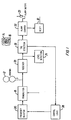
- Referring to figure 1, a security system for monitoring a defined area is shown generally by
numeral 10. Thesystem 10 consists of one ormore antennas 12 situated at, for example, the exit of a store (not shown) to be protected, and a plurality oftags 14 which may be attached to goods to be secured against, for example, shoplifting. Thetags 14 contain aresonant circuit 16 tuned to approximately the same frequency. Theantenna 12 is driven by atransmitter 18 at a frequency of theresonant circuit 16 of thetag 14. Thus, when thecircuit 16 is excited by thetransmitter 18, it starts to oscillate - even after the transmitter has stopped transmitting. This oscillation is received by a receiver circuit 20 coupled to the antenna. The output of the receiver 20 is coupled via a conditioning circuit to analarm 22. In a preferred embodiment, the antenna is used for both transmission and reception. Thus, the system need only one antenna to function. Other embodiments may use separate antennas. - In order for the system to provide the benefits of a fixed frequency system with improved detection range, the system includes a signal
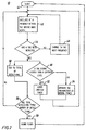
level detection unit 24 coupled to receive an output from the receiver 20 and driving the level of thetransmitter 18; the output from the receiver 20 also drives atag detection circuit 26 which, in turn, drivescontrol logic 28 coupled to afrequency selector 30 for operating thetransmitter 18 at a plurality of selected frequencies. The output from thetag detection circuit 26 is also provided to analarm counter 32 for driving thebuzzer 22 after a predetermined number of successive tag signals are detected. - Referring now to figure 2, the operation of the circuit will be described with reference to the
flow chart 40 illustrated therein. In the following description, reference will be made to the blocks indicated in figure 1. It may also be noted that the blocks shown in figure 1 will not be described in detail since the implementation thereof is straightforward and well known in the art. Thetransmitter 18 is made to sweep over a range of frequencies, typically 7.7 MHz to 8.7 MHz. However, rather than continuously sweep between these frequencies, the transmitter is tuned to fixed frequencies within the range, such as 7.7 MHz, 7.8 MHz, 7.9 MHz, 8.0 MHz, 8.1 MHz, 8.2 MHz, 8.3 MHz, 8.4, 8.5 MHz, 8.6 MHz, 8.7 MHz. Thus, thefrequency selector 30 may simply be a switchable series of capacitive elements for tuning a transmitter to each of the frequencies. Thus, at start up,control logic 28 will set the frequency selector to the lowest frequency and begins transmitting. Thetransmitter 18 thus oscillates at the selected frequency. This is shown asstep 42. If a tag is not detected by the receiver, thecontrol logic 28 signals thefrequency selector 30 to change the frequency as shown inblock 46. If on the other hand, a signal is detected, i.e., the receiver picks up an oscillation from a tag in the vicinity of the antenna, thetag detection circuit 26, which may simply be a comparator, generates an output signal which signals thecontrol logic 28 not to change the transmitter frequency, and increments the alarm counter 33 shown atblock 48. At the same time, thelevel detection circuit 24 determines whether the output from the receiver is above a predetermined level, block 50. If the received tag signal is above the predetermined level, implying that the tag is closer to the antenna, the level detector causes thetransmitter 18 to lower its output power by a predetermined amount, block 52. On the other hand, if the received signal is lower that the predetermined level, the transmitter is operated at its currently set power, block 54. - At the same time, the
alarm counter 32 determines, as shown inblock 56, if a maximum number of detections have been reached. If so, thealarm 22 is triggered shown inblock 58. It may be seen from the flow diagram that the system is reset after the alarm is sounded and the program operation begins at the block markedstart 41, whereas, if the alarm has not sounded, the system merely cycles back to begin atblock 42. It may be noted that thetransmitter 18 may simply incorporate circuitry to cycle through a predetermined number of power levels upon receipt of the signal fromlevel detection circuit 24 and the frequency selector may also cycle through the predetermined frequency ranges upon receipt of the signal from thecontrol logic circuit 28 and once the last frequency is encountered, to reset itself by cycling back to the lower start frequency. - In a preferred embodiment, the system will sound the alarm after approximately twelve sequential detections. Furthermore, it may be seen that if the changing of the frequency stops as soon as a tag is detected, and the system continues as a fixed frequency system, the time necessary to detect a tag is much shorter than a swept system and therefore, more systems may operate together as a fixed frequency system synchronized to the mains frequency.
- Furthermore, because the circuit adjusts the transmitter voltage to a lower voltage, if the received tag signal is higher than a predetermined threshold, the transmitter will not deactivate the tag. Thus, the system may operate at a high transmitter power, giving a long detection range, without deactivating tags close to the transmitter antenna.
- The system of figure 1 may cycle through a burst of 4 transmit/receive sequences of approximately 0.5 milliseconds and a pause of approximately 9.5 milliseconds for 50 Hz systems (7.8 milliseconds for 60 Hz systems). In the pause, other antennas can cycle through their transmit/receive sequence without disturbing each other.
- The antennas and transmitters are synchronized to the mains, and therefore no special synchronization cables are needed. The system may have a figure eight-shaped antenna loop, this antenna has the best detection of a horizontal tag, while a figure zero antenna loop has a better detection of a vertical tag. Combining these antennas in the system gives a uniform detection range of tags held in all possible orientations.
- Although the invention has been described with reference to certain specific embodiments, various modifications thereof will be apparent to those skilled in the art without departing from the spirit and scope of the invention as outlined in the claims appended hereto.
Claims (4)
- A security system for monitoring the presence of one or more objects in a monitored zone, said system comprising an antenna and at least one tag having a tuned resonant circuit associated with one or more objects to be monitored;a transmitter coupled to said antenna operable to transmit at one of a plurality of frequencies in response to a frequency selection signal, said transmitter operating said antenna for cyclic transmission of each of said plurality of frequencies within a repeatable transmission/receive sequence interrupted by pause intervals;a receiver coupled to said antenna and for producing a tag detection signal for stopping said cycling of said transmitter frequencies in response to a signal received at said receiver from said tag thereby causing said transmitter to transmit at a single frequency when a tag is detected.
- A system as defined in claim 1, including a level detection circuit coupled to an output of said receiver for decreasing the output power of said transmitter when said received signal is above a predetermined level.
- A security system for monitoring the presence of one or more objects in a monitored zone, said system comprising an antenna and at least one tag having a tuned resonant circuit associated with one or more objects to be monitored;a transmitter coupled to said antenna operable to transmit at one of a plurality of frequencies in response to a frequency selection signal;a receiver coupled to said antenna and for producing a detection signal and a level detection circuit coupled to an output of said receiver for decreasing the output power of said transmitter when said received signal is above a predetermine level.
- A system as defined in claim 3, wherein said transmitter operates said antenna for cyclic transmission of each of said plurality of frequencies within a repeatable transmission/receive sequence interrupted by pause intervals, and said receiver produces a detection signal for stopping said cycling of said transmitter frequencies in response to a signal received at said receiver from said tag thereby causing said transmitter to transmit at a single frequency when a tag is detected.
Priority Applications (1)
| Application Number | Priority Date | Filing Date | Title |
|---|---|---|---|
| EP03077707A EP1369833B1 (en) | 1998-12-09 | 1999-12-07 | Improved security system for monitoring the passage of items through defined zones |
Applications Claiming Priority (2)
| Application Number | Priority Date | Filing Date | Title |
|---|---|---|---|
| CA2255342 | 1998-12-09 | ||
| CA002255342A CA2255342C (en) | 1998-12-09 | 1998-12-09 | Security system for monitoring the passage of items through defined zones |
Related Child Applications (2)
| Application Number | Title | Priority Date | Filing Date |
|---|---|---|---|
| EP03077707A Division EP1369833B1 (en) | 1998-12-09 | 1999-12-07 | Improved security system for monitoring the passage of items through defined zones |
| EP03077707A Division-Into EP1369833B1 (en) | 1998-12-09 | 1999-12-07 | Improved security system for monitoring the passage of items through defined zones |
Publications (3)
| Publication Number | Publication Date |
|---|---|
| EP1008972A2 true EP1008972A2 (en) | 2000-06-14 |
| EP1008972A3 EP1008972A3 (en) | 2001-04-11 |
| EP1008972B1 EP1008972B1 (en) | 2004-04-28 |
Family
ID=4163076
Family Applications (2)
| Application Number | Title | Priority Date | Filing Date |
|---|---|---|---|
| EP99610077A Expired - Lifetime EP1008972B1 (en) | 1998-12-09 | 1999-12-07 | Improved security system for monitoring the passage of items through defined zones |
| EP03077707A Expired - Lifetime EP1369833B1 (en) | 1998-12-09 | 1999-12-07 | Improved security system for monitoring the passage of items through defined zones |
Family Applications After (1)
| Application Number | Title | Priority Date | Filing Date |
|---|---|---|---|
| EP03077707A Expired - Lifetime EP1369833B1 (en) | 1998-12-09 | 1999-12-07 | Improved security system for monitoring the passage of items through defined zones |
Country Status (5)
| Country | Link |
|---|---|
| US (1) | US6501381B1 (en) |
| EP (2) | EP1008972B1 (en) |
| AT (1) | ATE265726T1 (en) |
| CA (1) | CA2255342C (en) |
| DE (2) | DE69916759T2 (en) |
Cited By (3)
| Publication number | Priority date | Publication date | Assignee | Title |
|---|---|---|---|---|
| EP1020829A2 (en) * | 1999-01-14 | 2000-07-19 | George W. Kaltner | Deactivation prevention for electronic article surveillance systems |
| WO2002073563A2 (en) * | 2001-03-13 | 2002-09-19 | Sensormatic Electronics Corporation | Varying field electronic tag detection system |
| US6501381B1 (en) | 1998-12-09 | 2002-12-31 | 1336700 Ontario Inc. | Security system for monitoring the passage of items through defined zones |
Families Citing this family (10)
| Publication number | Priority date | Publication date | Assignee | Title |
|---|---|---|---|---|
| FR2819772B1 (en) * | 2001-01-22 | 2004-05-28 | Alstom | DEVICE AND METHOD FOR THE PUNCTUAL LOCATION OF A RAIL VEHICLE ALONG A RAIL TRACK EQUIPPED WITH BEACONS AND ANTENNA FOR EQUIPPING SUCH A DEVICE |
| US20040113939A1 (en) * | 2002-12-11 | 2004-06-17 | Eastman Kodak Company | Adaptive display system |
| DE102008060188A1 (en) * | 2008-11-28 | 2010-06-10 | Siemens Aktiengesellschaft | Method and device for distance measurement |
| RU2480837C2 (en) * | 2011-06-16 | 2013-04-27 | Федеральное государственное унитарное предприятие федеральный научно-производственный центр "Производственное объединение "Старт" им. М.В. Проценко" (ФГУП ФНПЦ "ПО "Старт" им. М.В. Проценко") | Method for hidden detection of trespasser in monitored area |
| RU2599527C1 (en) * | 2015-06-11 | 2016-10-10 | ОБЩЕСТВО С ОГРАНИЧЕННОЙ ОТВЕТСТВЕННОСТЬЮ НАУЧНО-ПРОИЗВОДСТВЕННОЕ ПРЕДПРИЯТИЕ "АВТОМАТИКА - С" (ООО НПП "Автоматика-С") | Method for combined protection of perimeter of extended object |
| RU2599523C1 (en) * | 2015-06-11 | 2016-10-10 | ОБЩЕСТВО С ОГРАНИЧЕННОЙ ОТВЕТСТВЕННОСТЬЮ НАУЧНО-ПРОИЗВОДСТВЕННОЕ ПРЕДПРИЯТИЕ "АВТОМАТИКА - С" (ООО НПП "Автоматика-С") | Method for combined protection of perimeter of extended object |
| RU2594478C1 (en) * | 2015-06-16 | 2016-08-20 | Федеральное государственное унитарное предприятие федеральный научно-производственный центр "Производственное объединение "Старт" им. М.В. Проценко" (ФГУП ФНПЦ ПО "Старт" им. М.В. Проценко") | Intelligent security alarm system with possibility of information exchange between detection |
| RU2595979C1 (en) * | 2015-07-13 | 2016-08-27 | Федеральное государственное унитарное предприятие федеральный научно-производственный центр "Производственное объединение "Старт" им. М.В. Проценко" (ФГУП ФНПЦ ПО "Старт" им. М.В. Проценко") | Method of detecting intruder using ultra-wideband signal (versions) |
| RU2683186C1 (en) * | 2018-06-04 | 2019-03-26 | Акционерное общество "Федеральный научно-производственный центр "Производственное объединение "Старт" им. М.В. Проценко" (АО "ФНПЦ ПО "Старт" им. М.В. Проценко") | Combined two-border system for protection of objects perimeters |
| CN112037452B (en) * | 2020-09-10 | 2023-02-21 | 成都威图芯晟科技有限公司 | Electronic article surveillance system, transmitter and surveillance signal generation method |
Citations (2)
| Publication number | Priority date | Publication date | Assignee | Title |
|---|---|---|---|---|
| EP0561062A1 (en) * | 1992-03-17 | 1993-09-22 | Moisei Samuel Granovsky | Method and electromagnetic security system for detection of protected objects in a surveillance zone |
| US5406262A (en) * | 1993-06-16 | 1995-04-11 | Security Tag Systems, Inc. | Adjusting magnetic bias field intensity in EAS presence detection system to enhance detection |
Family Cites Families (5)
| Publication number | Priority date | Publication date | Assignee | Title |
|---|---|---|---|---|
| US3771116A (en) * | 1972-01-12 | 1973-11-06 | Bendix Corp | Method and apparatus for imaging stationary and moving objects |
| US4274090A (en) * | 1980-02-19 | 1981-06-16 | Knogo Corporation | Detection of articles in adjacent passageways |
| DK164336C (en) | 1990-02-19 | 1992-11-02 | Karsten Gyde Pilested | SECURITY SYSTEM FOR MONITORING EMNERS, e.g. GOODS, PASSAGE FOR CERTAIN ZONES |
| CA2255342C (en) | 1998-12-09 | 2007-06-05 | Detectag Inc. | Security system for monitoring the passage of items through defined zones |
| US6034604A (en) * | 1999-01-14 | 2000-03-07 | Kaltner; George | Deactivation prevention for electronic article surveillance systems |
-
1998
- 1998-12-09 CA CA002255342A patent/CA2255342C/en not_active Expired - Fee Related
-
1999
- 1999-12-07 DE DE69916759T patent/DE69916759T2/en not_active Expired - Lifetime
- 1999-12-07 EP EP99610077A patent/EP1008972B1/en not_active Expired - Lifetime
- 1999-12-07 EP EP03077707A patent/EP1369833B1/en not_active Expired - Lifetime
- 1999-12-07 DE DE69938436T patent/DE69938436T2/en not_active Expired - Lifetime
- 1999-12-07 AT AT99610077T patent/ATE265726T1/en not_active IP Right Cessation
- 1999-12-09 US US09/457,384 patent/US6501381B1/en not_active Expired - Fee Related
Patent Citations (2)
| Publication number | Priority date | Publication date | Assignee | Title |
|---|---|---|---|---|
| EP0561062A1 (en) * | 1992-03-17 | 1993-09-22 | Moisei Samuel Granovsky | Method and electromagnetic security system for detection of protected objects in a surveillance zone |
| US5406262A (en) * | 1993-06-16 | 1995-04-11 | Security Tag Systems, Inc. | Adjusting magnetic bias field intensity in EAS presence detection system to enhance detection |
Cited By (7)
| Publication number | Priority date | Publication date | Assignee | Title |
|---|---|---|---|---|
| US6501381B1 (en) | 1998-12-09 | 2002-12-31 | 1336700 Ontario Inc. | Security system for monitoring the passage of items through defined zones |
| EP1020829A2 (en) * | 1999-01-14 | 2000-07-19 | George W. Kaltner | Deactivation prevention for electronic article surveillance systems |
| EP1020829A3 (en) * | 1999-01-14 | 2001-03-28 | George W. Kaltner | Deactivation prevention for electronic article surveillance systems |
| WO2002073563A2 (en) * | 2001-03-13 | 2002-09-19 | Sensormatic Electronics Corporation | Varying field electronic tag detection system |
| WO2002073563A3 (en) * | 2001-03-13 | 2003-04-10 | Sensormatic Electronics Corp | Varying field electronic tag detection system |
| US6906628B2 (en) | 2001-03-13 | 2005-06-14 | Sensormatic Electronics Corporation | Varying field electronic tag detection system |
| AU2002258498B2 (en) * | 2001-03-13 | 2006-11-09 | Sensormatic Electronics Llc | Varying field electronic tag detection system |
Also Published As
| Publication number | Publication date |
|---|---|
| DE69938436T2 (en) | 2009-04-09 |
| EP1369833A3 (en) | 2004-09-01 |
| ATE265726T1 (en) | 2004-05-15 |
| US6501381B1 (en) | 2002-12-31 |
| DE69916759T2 (en) | 2005-04-21 |
| DE69938436D1 (en) | 2008-05-08 |
| EP1008972A3 (en) | 2001-04-11 |
| CA2255342A1 (en) | 2000-06-09 |
| EP1008972B1 (en) | 2004-04-28 |
| CA2255342C (en) | 2007-06-05 |
| EP1369833B1 (en) | 2008-03-26 |
| DE69916759D1 (en) | 2004-06-03 |
| EP1369833A2 (en) | 2003-12-10 |
Similar Documents
| Publication | Publication Date | Title |
|---|---|---|
| US6501381B1 (en) | Security system for monitoring the passage of items through defined zones | |
| EP1204954B1 (en) | Electronic article security system employing variable time shifts | |
| KR100721164B1 (en) | Resonant Circuit Detection, Mearsurement and Deactivation System Employing a Numerically Controlled Oscillator | |
| US7170414B2 (en) | Systems and methods for optical reading and EAS tag sensing and deactivating at retail checkout | |
| EP1216464B1 (en) | Electronic article surveillance transmitter control using target range | |
| US20050052287A1 (en) | Wireless communication system | |
| US6271756B1 (en) | Security tag detection and localization system | |
| JP4903209B2 (en) | EAS system capable of synchronous transmission | |
| WO1982001255A1 (en) | Fm/am electronic security system | |
| US6034604A (en) | Deactivation prevention for electronic article surveillance systems | |
| US20060290589A1 (en) | Passive Resonant Reflector | |
| EP1157365B1 (en) | Article monitoring apparatus and system | |
| EP0516666B1 (en) | A security system for surveilling the passage of commodities through defined zones | |
| DK148106B (en) | THEFT PROTECTOR, NAMELY FOR STORE AREAS | |
| JP3174231B2 (en) | Anti-theft device | |
| JPH10143773A (en) | Shoplifting preventing device | |
| JPH08329368A (en) | Alarm device | |
| JPH0746673A (en) | Radio monitoring device and radio monitoring system |
Legal Events
| Date | Code | Title | Description |
|---|---|---|---|
| PUAI | Public reference made under article 153(3) epc to a published international application that has entered the european phase |
Free format text: ORIGINAL CODE: 0009012 |
|
| AK | Designated contracting states |
Kind code of ref document: A2 Designated state(s): AT BE CH CY DE DK ES FI FR GB GR IE IT LI LU MC NL PT SE |
|
| AX | Request for extension of the european patent |
Free format text: AL;LT;LV;MK;RO;SI |
|
| PUAL | Search report despatched |
Free format text: ORIGINAL CODE: 0009013 |
|
| AK | Designated contracting states |
Kind code of ref document: A3 Designated state(s): AT BE CH CY DE DK ES FI FR GB GR IE IT LI LU MC NL PT SE |
|
| AX | Request for extension of the european patent |
Free format text: AL;LT;LV;MK;RO;SI |
|
| 17P | Request for examination filed |
Effective date: 20010927 |
|
| AKX | Designation fees paid |
Free format text: AT BE CH CY DE DK ES FI FR GB GR IE IT LI LU MC NL PT SE |
|
| 17Q | First examination report despatched |
Effective date: 20030326 |
|
| RIN1 | Information on inventor provided before grant (corrected) |
Inventor name: PILESTED, KARSTEN GYDE |
|
| GRAP | Despatch of communication of intention to grant a patent |
Free format text: ORIGINAL CODE: EPIDOSNIGR1 |
|
| GRAS | Grant fee paid |
Free format text: ORIGINAL CODE: EPIDOSNIGR3 |
|
| GRAA | (expected) grant |
Free format text: ORIGINAL CODE: 0009210 |
|
| AK | Designated contracting states |
Kind code of ref document: B1 Designated state(s): AT BE CH CY DE DK ES FI FR GB GR IE IT LI LU MC NL PT SE |
|
| PG25 | Lapsed in a contracting state [announced via postgrant information from national office to epo] |
Ref country code: NL Free format text: LAPSE BECAUSE OF FAILURE TO SUBMIT A TRANSLATION OF THE DESCRIPTION OR TO PAY THE FEE WITHIN THE PRESCRIBED TIME-LIMIT Effective date: 20040428 Ref country code: LI Free format text: LAPSE BECAUSE OF FAILURE TO SUBMIT A TRANSLATION OF THE DESCRIPTION OR TO PAY THE FEE WITHIN THE PRESCRIBED TIME-LIMIT Effective date: 20040428 Ref country code: FR Free format text: LAPSE BECAUSE OF FAILURE TO SUBMIT A TRANSLATION OF THE DESCRIPTION OR TO PAY THE FEE WITHIN THE PRESCRIBED TIME-LIMIT Effective date: 20040428 Ref country code: FI Free format text: LAPSE BECAUSE OF FAILURE TO SUBMIT A TRANSLATION OF THE DESCRIPTION OR TO PAY THE FEE WITHIN THE PRESCRIBED TIME-LIMIT Effective date: 20040428 Ref country code: CY Free format text: LAPSE BECAUSE OF FAILURE TO SUBMIT A TRANSLATION OF THE DESCRIPTION OR TO PAY THE FEE WITHIN THE PRESCRIBED TIME-LIMIT Effective date: 20040428 Ref country code: CH Free format text: LAPSE BECAUSE OF FAILURE TO SUBMIT A TRANSLATION OF THE DESCRIPTION OR TO PAY THE FEE WITHIN THE PRESCRIBED TIME-LIMIT Effective date: 20040428 Ref country code: BE Free format text: LAPSE BECAUSE OF FAILURE TO SUBMIT A TRANSLATION OF THE DESCRIPTION OR TO PAY THE FEE WITHIN THE PRESCRIBED TIME-LIMIT Effective date: 20040428 Ref country code: AT Free format text: LAPSE BECAUSE OF FAILURE TO SUBMIT A TRANSLATION OF THE DESCRIPTION OR TO PAY THE FEE WITHIN THE PRESCRIBED TIME-LIMIT Effective date: 20040428 |
|
| REG | Reference to a national code |
Ref country code: GB Ref legal event code: FG4D |
|
| RIN1 | Information on inventor provided before grant (corrected) |
Inventor name: PILESTED, KARSTEN GYDE |
|
| REG | Reference to a national code |
Ref country code: CH Ref legal event code: EP |
|
| REG | Reference to a national code |
Ref country code: IE Ref legal event code: FG4D |
|
| REF | Corresponds to: |
Ref document number: 69916759 Country of ref document: DE Date of ref document: 20040603 Kind code of ref document: P |
|
| PG25 | Lapsed in a contracting state [announced via postgrant information from national office to epo] |
Ref country code: SE Free format text: LAPSE BECAUSE OF FAILURE TO SUBMIT A TRANSLATION OF THE DESCRIPTION OR TO PAY THE FEE WITHIN THE PRESCRIBED TIME-LIMIT Effective date: 20040728 Ref country code: GR Free format text: LAPSE BECAUSE OF FAILURE TO SUBMIT A TRANSLATION OF THE DESCRIPTION OR TO PAY THE FEE WITHIN THE PRESCRIBED TIME-LIMIT Effective date: 20040728 Ref country code: DK Free format text: LAPSE BECAUSE OF FAILURE TO SUBMIT A TRANSLATION OF THE DESCRIPTION OR TO PAY THE FEE WITHIN THE PRESCRIBED TIME-LIMIT Effective date: 20040728 |
|
| PG25 | Lapsed in a contracting state [announced via postgrant information from national office to epo] |
Ref country code: ES Free format text: LAPSE BECAUSE OF FAILURE TO SUBMIT A TRANSLATION OF THE DESCRIPTION OR TO PAY THE FEE WITHIN THE PRESCRIBED TIME-LIMIT Effective date: 20040808 |
|
| NLV1 | Nl: lapsed or annulled due to failure to fulfill the requirements of art. 29p and 29m of the patents act | ||
| REG | Reference to a national code |
Ref country code: CH Ref legal event code: PL |
|
| PG25 | Lapsed in a contracting state [announced via postgrant information from national office to epo] |
Ref country code: LU Free format text: LAPSE BECAUSE OF NON-PAYMENT OF DUE FEES Effective date: 20041207 Ref country code: IE Free format text: LAPSE BECAUSE OF NON-PAYMENT OF DUE FEES Effective date: 20041207 |
|
| PG25 | Lapsed in a contracting state [announced via postgrant information from national office to epo] |
Ref country code: MC Free format text: LAPSE BECAUSE OF NON-PAYMENT OF DUE FEES Effective date: 20041231 |
|
| PLBE | No opposition filed within time limit |
Free format text: ORIGINAL CODE: 0009261 |
|
| STAA | Information on the status of an ep patent application or granted ep patent |
Free format text: STATUS: NO OPPOSITION FILED WITHIN TIME LIMIT |
|
| EN | Fr: translation not filed | ||
| 26N | No opposition filed |
Effective date: 20050131 |
|
| REG | Reference to a national code |
Ref country code: IE Ref legal event code: MM4A |
|
| PG25 | Lapsed in a contracting state [announced via postgrant information from national office to epo] |
Ref country code: PT Free format text: LAPSE BECAUSE OF NON-PAYMENT OF DUE FEES Effective date: 20040928 |
|
| PGFP | Annual fee paid to national office [announced via postgrant information from national office to epo] |
Ref country code: IT Payment date: 20101228 Year of fee payment: 12 Ref country code: GB Payment date: 20101216 Year of fee payment: 12 |
|
| PGFP | Annual fee paid to national office [announced via postgrant information from national office to epo] |
Ref country code: DE Payment date: 20101222 Year of fee payment: 12 |
|
| GBPC | Gb: european patent ceased through non-payment of renewal fee |
Effective date: 20111207 |
|
| PG25 | Lapsed in a contracting state [announced via postgrant information from national office to epo] |
Ref country code: DE Free format text: LAPSE BECAUSE OF NON-PAYMENT OF DUE FEES Effective date: 20120703 Ref country code: GB Free format text: LAPSE BECAUSE OF NON-PAYMENT OF DUE FEES Effective date: 20111207 |
|
| REG | Reference to a national code |
Ref country code: DE Ref legal event code: R119 Ref document number: 69916759 Country of ref document: DE Effective date: 20120703 |
|
| PG25 | Lapsed in a contracting state [announced via postgrant information from national office to epo] |
Ref country code: IT Free format text: LAPSE BECAUSE OF NON-PAYMENT OF DUE FEES Effective date: 20111207 |