EP1008360A1 - Inhalation apparatus - Google Patents
Inhalation apparatus Download PDFInfo
- Publication number
- EP1008360A1 EP1008360A1 EP99309459A EP99309459A EP1008360A1 EP 1008360 A1 EP1008360 A1 EP 1008360A1 EP 99309459 A EP99309459 A EP 99309459A EP 99309459 A EP99309459 A EP 99309459A EP 1008360 A1 EP1008360 A1 EP 1008360A1
- Authority
- EP
- European Patent Office
- Prior art keywords
- diaphragm
- housing
- inhalation apparatus
- valve
- dispensing
- Prior art date
- Legal status (The legal status is an assumption and is not a legal conclusion. Google has not performed a legal analysis and makes no representation as to the accuracy of the status listed.)
- Granted
Links
- 230000000994 depressogenic effect Effects 0.000 claims description 6
- 238000011144 upstream manufacturing Methods 0.000 claims description 2
- 239000000443 aerosol Substances 0.000 abstract description 5
- 229940126601 medicinal product Drugs 0.000 abstract description 2
- 239000003570 air Substances 0.000 description 39
- 239000012530 fluid Substances 0.000 description 7
- 239000003814 drug Substances 0.000 description 5
- 230000008021 deposition Effects 0.000 description 3
- 239000007788 liquid Substances 0.000 description 3
- 210000004072 lung Anatomy 0.000 description 3
- 238000004519 manufacturing process Methods 0.000 description 3
- 230000007246 mechanism Effects 0.000 description 3
- 238000007789 sealing Methods 0.000 description 3
- 230000009471 action Effects 0.000 description 2
- 208000006673 asthma Diseases 0.000 description 2
- 230000009286 beneficial effect Effects 0.000 description 2
- 230000008901 benefit Effects 0.000 description 2
- 230000006835 compression Effects 0.000 description 2
- 238000007906 compression Methods 0.000 description 2
- 238000006073 displacement reaction Methods 0.000 description 2
- 238000001746 injection moulding Methods 0.000 description 2
- 239000000463 material Substances 0.000 description 2
- 230000002093 peripheral effect Effects 0.000 description 2
- 239000003380 propellant Substances 0.000 description 2
- 230000004044 response Effects 0.000 description 2
- 238000005096 rolling process Methods 0.000 description 2
- 239000012080 ambient air Substances 0.000 description 1
- 229920005549 butyl rubber Polymers 0.000 description 1
- 230000008859 change Effects 0.000 description 1
- 230000009429 distress Effects 0.000 description 1
- 229940079593 drug Drugs 0.000 description 1
- 229920001971 elastomer Polymers 0.000 description 1
- 239000000806 elastomer Substances 0.000 description 1
- 230000003434 inspiratory effect Effects 0.000 description 1
- 238000000034 method Methods 0.000 description 1
- 238000000465 moulding Methods 0.000 description 1
- 230000037452 priming Effects 0.000 description 1
- 230000008569 process Effects 0.000 description 1
- 230000029058 respiratory gaseous exchange Effects 0.000 description 1
- 239000000243 solution Substances 0.000 description 1
- 239000007921 spray Substances 0.000 description 1
- 230000001360 synchronised effect Effects 0.000 description 1
- 229920002725 thermoplastic elastomer Polymers 0.000 description 1
Images


Classifications
-
- A—HUMAN NECESSITIES
- A61—MEDICAL OR VETERINARY SCIENCE; HYGIENE
- A61M—DEVICES FOR INTRODUCING MEDIA INTO, OR ONTO, THE BODY; DEVICES FOR TRANSDUCING BODY MEDIA OR FOR TAKING MEDIA FROM THE BODY; DEVICES FOR PRODUCING OR ENDING SLEEP OR STUPOR
- A61M15/00—Inhalators
- A61M15/0091—Inhalators mechanically breath-triggered
-
- A—HUMAN NECESSITIES
- A61—MEDICAL OR VETERINARY SCIENCE; HYGIENE
- A61M—DEVICES FOR INTRODUCING MEDIA INTO, OR ONTO, THE BODY; DEVICES FOR TRANSDUCING BODY MEDIA OR FOR TAKING MEDIA FROM THE BODY; DEVICES FOR PRODUCING OR ENDING SLEEP OR STUPOR
- A61M15/00—Inhalators
- A61M15/009—Inhalators using medicine packages with incorporated spraying means, e.g. aerosol cans
Definitions
- This invention relates to dispensing apparatus for use with pressurised dispensing containers and in particular, but not exclusively, for apparatus for dispensing orally inhaled medicinal products in aerosol form.
- dispensing apparatus comprising a housing defining a socket for receiving, in use, a pressurised dispensing container of the type having a tubular valve stem biassed into an extended position and having first valve means operable to dispense fluid through the stem when the stem is depressed.
- the housing defines an airway extending from an inlet means, which is open to the atmosphere, to an outlet defined by a mouthpiece. Inhalation by a user results in an air flow through the airway.
- the apparatus further comprises an actuator, in which the stem is sealingly received in use such that the actuator and the stem together define a first chamber into which fluid is dispensable by operation of the first valve means.
- a second valve means normally closes the chamber and is actuatable to release fluid from the first chamber to flow into the airway.
- the second valve means comprises a valve member located externally of the first chamber and cooperable with a valve seat of the actuator.
- a flow sensor is arranged in the airway and operable to actuate the second valve means in response to a flow of air being sensed in the airway.
- the flow sensor is movable in response to the flow of air in a bore defined by the housing between first and second positions corresponding to closed and open conditions of the second valve means respectively.
- the flow sensor is connected directly to the valve member and provided with biassing means urging the flow sensor into the first position, in which the valve member is biassed into sealing contact with the valve seat.
- a flow sensor comprising a piston, which is axially movable in the bore, and guide means operable to guide the movement of the piston so as to maintain a lateral surface of the piston in spaced relationship from a side wall of the bore.
- a passageway is thus defined having a cross-section which is substantially uniform throughout the travel of the piston between the first and second positions.
- the passageway constituting a constricted portion of the airway, presents a substantially uniform impedance to the flow of air throughout the movement of the piston.
- a pressure drop is developed across the flow path. This pressure drop acts on the piston to define a force which is used to operate the device.
- An advantage of this arrangement is that the user experiences a constant impedance to the inhaled air flow throughout the inhalation process resulting in a slow and steady flow of air in which the atomised medicament is carried.
- Such a characteristic of flow rate has proved to be highly beneficial to the effective deposition of inhaled medicaments where deposition of an atomised spray in the user's lungs is intended.
- any discontinuity in the flow rate resulting from a change in impedance can result in a rapid increase in flow rate with consequent early deposition of the medicament in the throat or mouth of the user.
- a further advantage is that the uniformity of flow avoids any "dead spot" in the flow characteristic during which the user is prevented from receiving inhaled air, thereby avoiding unnecessary distress for the user who may for example be an asthmatic.
- a disadvantage of this arrangement has been found to be the significant variability in the cross-section of the air passageway due to typical manufacturing tolerances.
- the external diameter of the piston may be typically 30.00mm +/- 0.10mm and the internal diameter of the bore typically 30.60mm +/- 0.10mm.
- the minimum surface area of the air flow passageway might be 19.04mm 2 and the maximum surface area 38.08mm 2 . This represents a variability of +/- 33% approximately.
- Such variability in the cross-sectional area of the air flow passageway results in variability of the force available for operating the apparatus.
- the diaphragm comprises at least one aperture.
- the housing comprises at least one aperture.
- At least one aperture is provided in the second diaphragm element.
- a trigger extends from an exterior of the apparatus into contact with the diaphragm such that operation of the trigger moves the diaphragm axially.
- the trigger is rotatably pivoted on the housing such that one end protrudes through an aperture in the housing and the other end contacts the diaphragm.
- the apparatus further comprises an actuator having a projection, the diaphragm being connected to a tubular guide portion which is axially slidable on a guide surface of the projection to facilitate movement of the diaphragm.
- the actuator further defines an actuator chamber, valve seat and outlet nozzle, the tubular guide portion comprising a spigot on which a valve member of the valve means is mounted.
- the housing comprises a socket for receiving the pressurised dispensing container, the housing defining at least one port communicating between the socket and the mouthpiece at a location upstream of the diaphragm with respect to the direction of air flow during inhalation.
- a pressure drop of between 2.5 and 4 KPa is developed across the diaphragm when an airflow of 50 litres/minute is created by suction on the mouthpiece.
- the present invention also provides dispensing means comprising inhalation apparatus in combination with a pressurised dispensing container; said container having a tubular valve stem biased into an extended position and having valve means operable to dispense a metered dose of product through the valve stem when the valve stem is depressed.
- Figures 1 to 4 depict a dispensing apparatus of known type.
- the dispensing apparatus 1 is shown in combination with a pressurised dispensing container 2 with the apparatus oriented so as to be ready for use in an orientation in which the pressurised dispensing container extends vertically with valve 3 lowermost.
- the pressurised dispensing container 2 contains a product such as a liquid medicament mixed with a volatile propellant liquid.
- the apparatus comprises a housing 4 which includes an upwardly projecting cylindrical portion 5 defining a cylindrical recess or socket 6 in which the dispensing container 2 is axially and slidably received.
- the container 2 is a loose fit in the socket 6 such that air can freely flow through the socket through a peripheral space 39 between the container and the socket.
- the housing 4 further comprises a mouthpiece 11 defining a horizontally extending air duct 12 communicating with an outlet orifice 13 at a first end 14 of the mouthpiece.
- a second end 15 of the mouthpiece 11 communicates with a chamber 17 in the bottom of the housing 4.
- a tubular valve stem 7 projects downwardly from the pressurised dispensing container 2.
- the container has a valve 3 located internally of the container 2, which are actuated by axial depression of the valve stem 7 against internally provided spring bias to dispense a metered dose of product through the valve stem 7.
- valve stem 7 is received sealingly in a bore of a tubular actuator 8.
- the bore includes an annular shoulder 9 which acts as a stop limiting the extent to which the valve stem 7 extends within the actuator 8.
- the actuator 8 is received as a snug fit within a downwardly extending tubular member 10 formed integrally with the housing 4.
- the chamber 17 is closed by a cap 19.
- a wall 20 separates the cylindrical portion 5 and chamber 17.
- the wall 20 is provided with three circumferentially equispaced inlet ports 21, 22 and 23 allowing air to enter the chamber 17, from the peripheral space 39 in the cylinder socket 6 and from the exterior of the housing.
- the outlet orifice 13 is of oval cross-section so as to be comfortably received in the mouth of a user.
- the air duct 12 extends from the inlet ports 21, 22 and 23 through the chamber 17 and the mouthpiece 11 to the outlet orifice 13.
- the tubular member 10 has an end wall 24 defining an aperture 25 communicating with an annular space 26 formed between the end wall 24 and the actuator 8.
- a nozzle 27 defined by the tubular member 10 communicates with the annular space 26 and is oriented to release fluid from the annular space into the chamber 17 in a direction towards the outlet orifice 13.
- a piston 32 is vertically slidably received in the chamber 17, to which is attached a substantially tubular guide 33 which is co-axially mounted on the tubular member 10 and is slidable thereon.
- a boss 34 projects downwardly from the guide 33 and a helical compression spring 35 is located on the boss 34 and extends into contact with the wall 19 so as to bias the piston 32 upwardly.
- a spigot 31 projects upwardly from an end wall of the piston tubular element 32a.
- An actuator valve 28 is formed in the tubular projection 10 by an annular valve seat 29 at the lower end of the actuator 8 and a resilient valve member 30 which extends from the bore 17 into the annular space 26 and is normally urged into sealing contact with the valve seat 29 by a spigot 31.
- the valve member 30 has a cylindrical body which is recessed to accommodate the spigot 31 as an interference fit so that the spigot 31 and valve member 30 are connected sufficiently firmly to enable the valve member 30 to be positively unseated from the valve seat when the spigot is retracted.
- the valve member 30 is recessed so as to be penetrated by the spigot 31 which is received as an interference fit thereby firmly attaching the valve member to the spigot 31.
- the valve member 30 is a sliding fit within the aperture 25 and is provided with a radially projecting flange 37 of greater diameter than the aperture 25 so that the flange 37 acts as a stop limiting downward motion of the valve member 30 through the aperture 25.
- the piston 32 is shown in Figures 1 and 2 in its normal rest position in which it lies adjacent the housing wall 20. Its diameter is such that a restricted flow of air is allowed from the inlet ports 21, 22 and 23 into the chamber 17. Typically, the piston 32 is of 30.00mm diameter and the chamber 17 is dimensioned to provide a clearance of 0.30mm between each side of the piston 32 and chamber 17. A restricted annular air passageway is thereby defined between the piston 32 and walls of the chamber 17.
- the ports 21, 22 and 23 are, in contrast, dimensioned to provide a greater cross-sectional area for the passage of air.
- a user holds the housing 4 with the cylindrical portion 5 oriented vertically as illustrated in Figures 1 to 4, and inserts the mouthpiece 11 into their mouth.
- the user depresses the pressurised dispensing container 2 relative to the housing 4 so as to actuate the container valve 3.
- Actuation of the container valve 3 results in a metered dose of pressurised product entering the actuator chamber 36, which is closed off by the actuator valve 28.
- the user then inhales through the mouthpiece 11, thereby reducing the air pressure within the housing chamber 17.
- the piston 32 is subjected to a downward force because of an imbalance of air pressure above and below the piston since the air pressure above the piston 32 is maintained at ambient air pressure via the inlet ports 21, 22 and 23.
- the piston 32 is thereby urged downwardly against the spring bias of spring 35.
- the spigot 31 on the tubular guide 33 also moves downwardly thereby unseating the resilient valve member 30 from the valve seat 29 so that the pressurised product escapes from the actuator chamber 36 into the annular space 26.
- dissolved propellant in liquid form boils off from the dispensed dose causing the escaping product to rapidly expand. This expansion assists in further displacing the valve member 30 away from the seat 29. Displacement of the valve member 30 away from the seat is limited by engagement between the flange 37 and the end wall 24 of the tubular member 10.
- Fluid pressure acting on the valve member 30 provides sealing action between the flange 37 and the end wall 24 so that pressurised fluid cannot escape through the aperture 25.
- the pressurised fluid within the annular space 26 then escapes via the nozzle 27 as shown in Figure 3.
- the piston 32 thereby constitutes a flow sensor which detects the flow of air in the duct 12 and which enables the second valve means 28 to be actuated to dispense the metered dose in synchronisation with the inhalation of air.
- Air is drawn during inhalation through the air duct 12 via the inlet ports 21, 22 and 23 and passes peripherally around the piston 32 into the chamber 17 and thereafter is inhaled through the mouthpiece 11.
- the product dispensed through the nozzle 27 is mixed with the inhaled air and is administered to the lungs of the user.
- the mouthpiece may be provided with a cover (not shown) to prevent the ingress of debris when the apparatus 1 is not in use.
- the apparatus 1 may also optionally include a mechanism for retaining the container 2 in its depressed condition throughout the dispensing operation. This is advantageous where the container valve 3 is of a type which vents to atmosphere the internal bore of the valve stem when the container valve 3 is in the closed condition. It is therefore important for the container 2 to remain depressed relative to the housing 4 until after the valve means 28 has been actuated to dispense the dose into the inhaled air.
- Figures 5 to 7 show a first embodiment of dispensing apparatus according to the present invention. Those components of like design and function to components of the prior art embodiment of Figures 1 to 4 have been given like reference numerals.
- piston 32 is replaced by a substantially annular diaphragm, generally depicted by reference 60.
- the diaphragm 60 comprises two essentially rigid elements.
- a first is a ring-shaped element 66 which is attached to the fixed body of the apparatus adjacent the housing wall 20.
- the second is an annular element 62 which extends laterally across chamber 17.
- the first and second elements 66, 62 of the diaphragm 60 are connected by a flexible member 61, preferably in the form of a rolling seal which allows vertical displacement of the second diaphragm element 62 relative to the first diaphragm element 66, whilst maintaining an air tight seal therebetween.
- the second diaphragm element 62 is attached to the tubular guide 33 which, as in the prior art, is co-axially mounted on the tubular projection 10 and slidably thereon.
- a boss 34 projects downwardly from the guide 33 and a helical compression spring 35 is located on the boss 34 and extends into contact with the cap 19, so as to bias the tubular guide 33 and second diaphragm element 62 upwardly.
- the second diaphragm element 62 is provided with a number of apertures 64, say, four holes of equal diameter.
- the device of the present invention functions similarly to the device of Figures 1 to 4.
- Figure 5 shows the apparatus prior to inhalation by the user.
- the second diaphragm element 62 As the user inhales orally through the mouthpiece 11 it is the second diaphragm element 62 which is subjected to a downward force because of an imbalance of air pressure above and below the diaphragm 60.
- the second diaphragm element 62 is urged downwardly against the biasing of the spring 35.
- Downward movement of the second diaphragm element 62 and tubular guide 33 results in actuation of the cylinder valve means 30, as shown in Figure 6, and then the second valve means 28 as shown in Figure 7 and as described in the prior art embodiment of Figures 1 to 4.
- Figure 8 shows a second embodiment of dispensing apparatus according to the present invention.
- the second embodiment is identical to the first embodiment with the exception that there are no apertures in the second diaphragm element 62. Rather the diaphragm 60 forms an air-tight seal across the housing 4 at the base of the cylindrical portion 5.
- One or more apertures 74 are instead provided in the housing 4 allowing flow of air between an exterior of the apparatus 1 and chamber 17.
- Operation of the apparatus is the same as in the first embodiment.
- a user inhales air flows from the exterior of the apparatus through apertures 74 and mouthpiece 11.
- the second diaphragm element is subjected to a downward force because of an imbalance of air pressure above and below the diaphragm.
- a third embodiment is shown in Figures 9 and 10.
- the apparatus is similar to that of the first embodiment except for the provision of a means for "priming" or test operating the apparatus.
- a trigger 80 is provided rotatably mounted on a pivot 81 on housing 5.
- One end 83 of the trigger 80 extends protrudingly through a hole 82 in the housing 5 such that the trigger is accessible from an exterior of the apparatus 1.
- the other end 84 of the trigger 80 extends into an interior of the apparatus 1 such that it contacts an upper surface of the second diaphragm element 62 when the second diaphragm element is in the non-dispensing position as shown in Figure 9.
- the user depresses the dispensing container 2 relative to the housing 5.
- a metered dose of pressurised product is dispensed into actuator chamber 36 which is closed off by the actuator valve 28.
- the user presses end 83 of trigger 80.
- the trigger 80 rotates about pivot 81 such that end 84 moves axially downwards relative to the housing 5.
- Downward movement of end 84 causes the second diaphragm element 62 to also move downwardly, into the position shown in Figure 10, operating the actuator valve 28 in the same manner as the previous embodiments to dispense the product as an aerosol.
- the trigger means of the third embodiment is equally applicable for use with the apparatus of the second embodiment in which diaphragm 60 does not contain any apertures.
- the diaphragm 60 need not be round, as described in the embodiments above, but may be any desired size and shape to fit within a particular size and shape of housing.
- the diaphragm 60 may be made of any suitable material having the required flexible and resilient characteristics. Such materials include thermoplastic elastomers, for example Hytrel (RTM), and cured elastomers, for example Buna (RTM) N or butyl rubber.
- the diaphragm 60 may be manufactured as a single unitary injection moulding, two-piece injection moulding or by assembly of separate components.
Abstract
Description
- This invention relates to dispensing apparatus for use with pressurised dispensing containers and in particular, but not exclusively, for apparatus for dispensing orally inhaled medicinal products in aerosol form.
- Various means have been proposed to synchronise the release of an aerosol product into a mouthpiece of a dispensing apparatus in a manner which is synchronised with the inhalation of breath by a user. Such synchronisation is important in ensuring that as much as possible of the dispensed dose reaches the lungs of the user. This is of particular importance when administering drugs for the relief of asthma.
- It has been proposed in GB 1392192 to provide a pivoted vane mechanism to sense air flow and release the aerosol product as a result of the user's inspiratory effort. Such a mechanism is difficult to manufacture to the required tolerance for controlled and repeatable performance in oral inhalation due to difficulties in moulding and distortions appearing in the moulded elements. There remains a need to provide a practical solution which will be suitable for production on a commercial scale.
- It is known from US 4576157 to provide dispensing apparatus comprising a housing defining a socket for receiving, in use, a pressurised dispensing container of the type having a tubular valve stem biassed into an extended position and having first valve means operable to dispense fluid through the stem when the stem is depressed. The housing defines an airway extending from an inlet means, which is open to the atmosphere, to an outlet defined by a mouthpiece. Inhalation by a user results in an air flow through the airway. The apparatus further comprises an actuator, in which the stem is sealingly received in use such that the actuator and the stem together define a first chamber into which fluid is dispensable by operation of the first valve means. A second valve means normally closes the chamber and is actuatable to release fluid from the first chamber to flow into the airway. The second valve means comprises a valve member located externally of the first chamber and cooperable with a valve seat of the actuator. A flow sensor is arranged in the airway and operable to actuate the second valve means in response to a flow of air being sensed in the airway. The flow sensor is movable in response to the flow of air in a bore defined by the housing between first and second positions corresponding to closed and open conditions of the second valve means respectively. The flow sensor is connected directly to the valve member and provided with biassing means urging the flow sensor into the first position, in which the valve member is biassed into sealing contact with the valve seat.
- It is further known from EP 0476991 to provide a dispensing apparatus in which a flow sensor is provided comprising a piston, which is axially movable in the bore, and guide means operable to guide the movement of the piston so as to maintain a lateral surface of the piston in spaced relationship from a side wall of the bore. A passageway is thus defined having a cross-section which is substantially uniform throughout the travel of the piston between the first and second positions. The passageway, constituting a constricted portion of the airway, presents a substantially uniform impedance to the flow of air throughout the movement of the piston. As the user inhales, a pressure drop is developed across the flow path. This pressure drop acts on the piston to define a force which is used to operate the device.
- An advantage of this arrangement is that the user experiences a constant impedance to the inhaled air flow throughout the inhalation process resulting in a slow and steady flow of air in which the atomised medicament is carried. Such a characteristic of flow rate has proved to be highly beneficial to the effective deposition of inhaled medicaments where deposition of an atomised spray in the user's lungs is intended. In contrast, any discontinuity in the flow rate resulting from a change in impedance can result in a rapid increase in flow rate with consequent early deposition of the medicament in the throat or mouth of the user. A further advantage is that the uniformity of flow avoids any "dead spot" in the flow characteristic during which the user is prevented from receiving inhaled air, thereby avoiding unnecessary distress for the user who may for example be an asthmatic.
- A disadvantage of this arrangement has been found to be the significant variability in the cross-section of the air passageway due to typical manufacturing tolerances. For example, the external diameter of the piston may be typically 30.00mm +/- 0.10mm and the internal diameter of the bore typically 30.60mm +/- 0.10mm. Thus, the minimum surface area of the air flow passageway might be 19.04mm2 and the maximum surface area 38.08mm2. This represents a variability of +/- 33% approximately. Such variability in the cross-sectional area of the air flow passageway results in variability of the force available for operating the apparatus.
- According to the present invention there is provided inhalation apparatus for dispensing a product comprising a housing adapted to receive a pressurised dispensing container, and a mouthpiece, a duct for conveying, in use, product from the container to the mouthpiece, valve means movable between a first position in which the duct is closed and a second position in which the duct is open, and a flow sensor being activatable, by means of an airflow created when a user applies suction to the mouthpiece, to move the valve means into its second position, wherein the flow sensor comprises a diaphragm and the diaphragm and/or housing is provided with at least one aperture, wherein the diaphragm comprises a first element connected to the housing and a second element axially slidably movable relative thereto, the first and second diaphragm elements being connected by a flexible member.
- In one embodiment the diaphragm comprises at least one aperture.
- In another embodiment the housing comprises at least one aperture.
- In another embodiment at least one aperture is provided in the second diaphragm element.
- Optionally a trigger extends from an exterior of the apparatus into contact with the diaphragm such that operation of the trigger moves the diaphragm axially.
- Preferably the trigger is rotatably pivoted on the housing such that one end protrudes through an aperture in the housing and the other end contacts the diaphragm.
- Preferably the apparatus further comprises an actuator having a projection, the diaphragm being connected to a tubular guide portion which is axially slidable on a guide surface of the projection to facilitate movement of the diaphragm.
- The actuator further defines an actuator chamber, valve seat and outlet nozzle, the tubular guide portion comprising a spigot on which a valve member of the valve means is mounted.
- In one embodiment the housing comprises a socket for receiving the pressurised dispensing container, the housing defining at least one port communicating between the socket and the mouthpiece at a location upstream of the diaphragm with respect to the direction of air flow during inhalation.
- Typically a pressure drop of between 2.5 and 4 KPa is developed across the diaphragm when an airflow of 50 litres/minute is created by suction on the mouthpiece.
- The present invention also provides dispensing means comprising inhalation apparatus in combination with a pressurised dispensing container; said container having a tubular valve stem biased into an extended position and having valve means operable to dispense a metered dose of product through the valve stem when the valve stem is depressed.
- Embodiments of the present invention will now be described by way of example only and with reference to the accompanying drawings of which:-
- Figure 1 is a sectional side elevation of a prior art dispensing apparatus, including a pressurised dispensing container;
- Figure 2 is a sectional side elevation of a part of the dispensing apparatus of Figure 1 in which the pressurised dispensing container has been depressed to actuate a first valve means;
- Figure 3 is a sectional side elevation of a part of the dispensing apparatus of Figure 1 in which the dispensed product is released into a flow of inhaled air;
- Figure 4 is a plan view of the dispensing apparatus of Figures 1 to 3, with the pressurised dispensing container omitted;
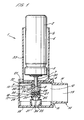
- Figure 5 is a sectional side elevation of a part of the dispensing apparatus in accordance with a first embodiment of the present invention, including a pressurised dispensing container, the apparatus being in a first, non-dispensing position;
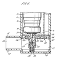
- Figure 6 is a sectional side elevation of the part of the dispensing apparatus of Figure 5, the apparatus being in a second, intermediate position;
- Figure 7 is a sectional side elevation of the part of the dispensing apparatus of Figure 5, the apparatus being in a third, dispensing position;
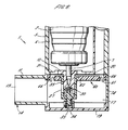
- Figure 8 is a sectional side elevation of a part of the dispensing apparatus in accordance with a second embodiment of the present invention, including a pressurised dispensing container, the apparatus being in a first, non-dispensing position;
- Figure 9 is a sectional side elevation of a part of the dispensing apparatus in accordance with a third embodiment of the present invention, including a pressurised dispensing container, the apparatus being in a first, non-dispensing position; and
- Figure 10 is a sectional side elevation of a part of the dispensing apparatus of Figure 9, including a pressurised dispensing container, the apparatus being in a second, dispensing position.
-
- Figures 1 to 4 depict a dispensing apparatus of known type. In Figure 1 the dispensing apparatus 1 is shown in combination with a
pressurised dispensing container 2 with the apparatus oriented so as to be ready for use in an orientation in which the pressurised dispensing container extends vertically withvalve 3 lowermost. The pressuriseddispensing container 2 contains a product such as a liquid medicament mixed with a volatile propellant liquid. - In the following description, the reference to vertical and horizontal orientation of components of the apparatus 1 refer to orientations of such components when the apparatus is held in its normal working orientation shown in Figure 1.
- The apparatus comprises a housing 4 which includes an upwardly projecting
cylindrical portion 5 defining a cylindrical recess orsocket 6 in which the dispensingcontainer 2 is axially and slidably received. Thecontainer 2 is a loose fit in thesocket 6 such that air can freely flow through the socket through aperipheral space 39 between the container and the socket. - The housing 4 further comprises a
mouthpiece 11 defining a horizontally extendingair duct 12 communicating with anoutlet orifice 13 at afirst end 14 of the mouthpiece. Asecond end 15 of themouthpiece 11 communicates with achamber 17 in the bottom of the housing 4. - A tubular valve stem 7 projects downwardly from the
pressurised dispensing container 2. The container has avalve 3 located internally of thecontainer 2, which are actuated by axial depression of thevalve stem 7 against internally provided spring bias to dispense a metered dose of product through thevalve stem 7. - The
valve stem 7 is received sealingly in a bore of a tubular actuator 8. The bore includes anannular shoulder 9 which acts as a stop limiting the extent to which thevalve stem 7 extends within the actuator 8. - The actuator 8 is received as a snug fit within a downwardly extending
tubular member 10 formed integrally with the housing 4. - The
chamber 17 is closed by acap 19. Awall 20 separates thecylindrical portion 5 andchamber 17. Thewall 20 is provided with three circumferentiallyequispaced inlet ports chamber 17, from theperipheral space 39 in thecylinder socket 6 and from the exterior of the housing. Theoutlet orifice 13 is of oval cross-section so as to be comfortably received in the mouth of a user. - The
air duct 12 extends from theinlet ports chamber 17 and themouthpiece 11 to theoutlet orifice 13. - The
tubular member 10 has anend wall 24 defining anaperture 25 communicating with anannular space 26 formed between theend wall 24 and the actuator 8. Anozzle 27 defined by thetubular member 10 communicates with theannular space 26 and is oriented to release fluid from the annular space into thechamber 17 in a direction towards theoutlet orifice 13. - A
piston 32 is vertically slidably received in thechamber 17, to which is attached a substantiallytubular guide 33 which is co-axially mounted on thetubular member 10 and is slidable thereon. Aboss 34 projects downwardly from theguide 33 and ahelical compression spring 35 is located on theboss 34 and extends into contact with thewall 19 so as to bias thepiston 32 upwardly. Aspigot 31 projects upwardly from an end wall of the piston tubular element 32a. - An
actuator valve 28 is formed in thetubular projection 10 by anannular valve seat 29 at the lower end of the actuator 8 and aresilient valve member 30 which extends from thebore 17 into theannular space 26 and is normally urged into sealing contact with thevalve seat 29 by aspigot 31. Thevalve member 30 has a cylindrical body which is recessed to accommodate thespigot 31 as an interference fit so that thespigot 31 andvalve member 30 are connected sufficiently firmly to enable thevalve member 30 to be positively unseated from the valve seat when the spigot is retracted. Thevalve member 30 is recessed so as to be penetrated by thespigot 31 which is received as an interference fit thereby firmly attaching the valve member to thespigot 31. Thevalve member 30 is a sliding fit within theaperture 25 and is provided with a radially projecting flange 37 of greater diameter than theaperture 25 so that the flange 37 acts as a stop limiting downward motion of thevalve member 30 through theaperture 25. - The
piston 32 is shown in Figures 1 and 2 in its normal rest position in which it lies adjacent thehousing wall 20. Its diameter is such that a restricted flow of air is allowed from theinlet ports chamber 17. Typically, thepiston 32 is of 30.00mm diameter and thechamber 17 is dimensioned to provide a clearance of 0.30mm between each side of thepiston 32 andchamber 17. A restricted annular air passageway is thereby defined between thepiston 32 and walls of thechamber 17. Theports - The actuator 8 and the hollow
tubular valve stem 7 together define anactuator chamber 36 which, in use, is closed at its upper end by thecontainer valve 3 and, at its lower end, by theactuator valve 28. - In use, a user holds the housing 4 with the
cylindrical portion 5 oriented vertically as illustrated in Figures 1 to 4, and inserts themouthpiece 11 into their mouth. The user depresses the pressuriseddispensing container 2 relative to the housing 4 so as to actuate thecontainer valve 3. Actuation of thecontainer valve 3 results in a metered dose of pressurised product entering theactuator chamber 36, which is closed off by theactuator valve 28. The user then inhales through themouthpiece 11, thereby reducing the air pressure within thehousing chamber 17. Thepiston 32 is subjected to a downward force because of an imbalance of air pressure above and below the piston since the air pressure above thepiston 32 is maintained at ambient air pressure via theinlet ports piston 32 is thereby urged downwardly against the spring bias ofspring 35. As thepiston 32 moves downwardly, thespigot 31 on thetubular guide 33 also moves downwardly thereby unseating theresilient valve member 30 from thevalve seat 29 so that the pressurised product escapes from theactuator chamber 36 into theannular space 26. As the product begins to escape, dissolved propellant in liquid form boils off from the dispensed dose causing the escaping product to rapidly expand. This expansion assists in further displacing thevalve member 30 away from theseat 29. Displacement of thevalve member 30 away from the seat is limited by engagement between the flange 37 and theend wall 24 of thetubular member 10. Fluid pressure acting on thevalve member 30 provides sealing action between the flange 37 and theend wall 24 so that pressurised fluid cannot escape through theaperture 25. The pressurised fluid within theannular space 26 then escapes via thenozzle 27 as shown in Figure 3. Thepiston 32 thereby constitutes a flow sensor which detects the flow of air in theduct 12 and which enables the second valve means 28 to be actuated to dispense the metered dose in synchronisation with the inhalation of air. - Air is drawn during inhalation through the
air duct 12 via theinlet ports piston 32 into thechamber 17 and thereafter is inhaled through themouthpiece 11. The product dispensed through thenozzle 27 is mixed with the inhaled air and is administered to the lungs of the user. - Releasing the manual pressure on the pressurised
dispensing container 2 allows it to resume its normal position, as shown in Figure 1, and at the end of inhalation thepiston 32 and guide 33 return to their rest positions as shown in Figure 1 under action of thespring 35. The dispensing apparatus 1 is then ready for re-use. - The mouthpiece may be provided with a cover (not shown) to prevent the ingress of debris when the apparatus 1 is not in use.
- The apparatus 1 may also optionally include a mechanism for retaining the
container 2 in its depressed condition throughout the dispensing operation. This is advantageous where thecontainer valve 3 is of a type which vents to atmosphere the internal bore of the valve stem when thecontainer valve 3 is in the closed condition. It is therefore important for thecontainer 2 to remain depressed relative to the housing 4 until after the valve means 28 has been actuated to dispense the dose into the inhaled air. - Figures 5 to 7 show a first embodiment of dispensing apparatus according to the present invention. Those components of like design and function to components of the prior art embodiment of Figures 1 to 4 have been given like reference numerals.
- In the first embodiment of the present invention,
piston 32 is replaced by a substantially annular diaphragm, generally depicted byreference 60. Thediaphragm 60 comprises two essentially rigid elements. A first is a ring-shapedelement 66 which is attached to the fixed body of the apparatus adjacent thehousing wall 20. The second is anannular element 62 which extends laterally acrosschamber 17. The first andsecond elements diaphragm 60 are connected by aflexible member 61, preferably in the form of a rolling seal which allows vertical displacement of thesecond diaphragm element 62 relative to thefirst diaphragm element 66, whilst maintaining an air tight seal therebetween. Thesecond diaphragm element 62 is attached to thetubular guide 33 which, as in the prior art, is co-axially mounted on thetubular projection 10 and slidably thereon. Aboss 34 projects downwardly from theguide 33 and ahelical compression spring 35 is located on theboss 34 and extends into contact with thecap 19, so as to bias thetubular guide 33 andsecond diaphragm element 62 upwardly. - The
second diaphragm element 62 is provided with a number ofapertures 64, say, four holes of equal diameter. - It has been found that significantly greater control over the variability of the area of the air flow passageway may be achieved by the use of apertures in such a rolling
diaphragm 60 compared to the use of achamber 17 andconcentric piston 32. For example, if each of four holes has a diameter of 2.80mm manufactured to a tolerance of +/- 0.05mm, the maximum cross-sectional area of the air flow passageway equals 25.52mm2 and the minimum area equals 23.75mm2. Thus, the variability is only approximately +/- 3% to 4%. This is significantly less than the +/- 33% variability of the prior art devices. - In use, the device of the present invention functions similarly to the device of Figures 1 to 4. Figure 5 shows the apparatus prior to inhalation by the user. As the user inhales orally through the
mouthpiece 11 it is thesecond diaphragm element 62 which is subjected to a downward force because of an imbalance of air pressure above and below thediaphragm 60. As a result, thesecond diaphragm element 62 is urged downwardly against the biasing of thespring 35. Downward movement of thesecond diaphragm element 62 andtubular guide 33 results in actuation of the cylinder valve means 30, as shown in Figure 6, and then the second valve means 28 as shown in Figure 7 and as described in the prior art embodiment of Figures 1 to 4. - It has been found that the best results in use of inhalation apparatus is obtained where the user of the apparatus feels some resistance to breathing when they start to inhale. As a result it has been found beneficial to make the air flow passageway as restricted as practical since this results in a higher pressure drop across the diaphragm. As a result a smaller diaphragm may be used to create the necessary operating force. This allows the overall dimensions of the dispensing apparatus to be minimised. In practice it has been found that the best results are obtained where the size and positioning of the
air flow apertures 64 is such that a pressure drop of between 2.5 and 4 KPa is developed across the diaphragm when operated at a typical flow rate of 50 litres/minute of air. - Figure 8 shows a second embodiment of dispensing apparatus according to the present invention. The second embodiment is identical to the first embodiment with the exception that there are no apertures in the
second diaphragm element 62. Rather thediaphragm 60 forms an air-tight seal across the housing 4 at the base of thecylindrical portion 5. One ormore apertures 74 are instead provided in the housing 4 allowing flow of air between an exterior of the apparatus 1 andchamber 17. - Operation of the apparatus is the same as in the first embodiment. As a user inhales air flows from the exterior of the apparatus through
apertures 74 andmouthpiece 11. In the same manner as the first embodiment, the second diaphragm element is subjected to a downward force because of an imbalance of air pressure above and below the diaphragm. - A third embodiment is shown in Figures 9 and 10. The apparatus is similar to that of the first embodiment except for the provision of a means for "priming" or test operating the apparatus. A
trigger 80 is provided rotatably mounted on apivot 81 onhousing 5. Oneend 83 of thetrigger 80 extends protrudingly through ahole 82 in thehousing 5 such that the trigger is accessible from an exterior of the apparatus 1. Theother end 84 of thetrigger 80 extends into an interior of the apparatus 1 such that it contacts an upper surface of thesecond diaphragm element 62 when the second diaphragm element is in the non-dispensing position as shown in Figure 9. - In use, either to prime the dispensing
container 2 or test actuate the apparatus 1, the user depresses the dispensingcontainer 2 relative to thehousing 5. As in the previous embodiments, a metered dose of pressurised product is dispensed intoactuator chamber 36 which is closed off by theactuator valve 28. Then, instead of inhaling, the user pressesend 83 oftrigger 80. Thetrigger 80 rotates aboutpivot 81 such thatend 84 moves axially downwards relative to thehousing 5. Downward movement ofend 84 causes thesecond diaphragm element 62 to also move downwardly, into the position shown in Figure 10, operating theactuator valve 28 in the same manner as the previous embodiments to dispense the product as an aerosol. - The trigger means of the third embodiment is equally applicable for use with the apparatus of the second embodiment in which diaphragm 60 does not contain any apertures.
- The
diaphragm 60 need not be round, as described in the embodiments above, but may be any desired size and shape to fit within a particular size and shape of housing. Thediaphragm 60 may be made of any suitable material having the required flexible and resilient characteristics. Such materials include thermoplastic elastomers, for example Hytrel (RTM), and cured elastomers, for example Buna (RTM) N or butyl rubber. - The
diaphragm 60 may be manufactured as a single unitary injection moulding, two-piece injection moulding or by assembly of separate components.
Claims (11)
- Inhalation apparatus for dispensing a product comprising a housing (4) adapted to receive a pressurised dispensing container (2), and a mouthpiece (11), a duct for conveying, in use, product from the container to the mouthpiece, valve means (28) movable between a first position in which the duct is closed and a second position in which the duct is open, and a flow sensor (60) being activatable, by means of an airflow created when a user applies suction to the mouthpiece, to move the valve means into its second position, wherein the flow sensor comprises a diaphragm (60) and the diaphragm and/or housing is provided with at least one aperture (64), characterised in that the diaphragm comprises a first element (66) connected to the housing and a second element (62) axially slidably movable relative thereto, the first and second diaphragm elements being connected by a flexible member (61).
- Inhalation apparatus as claimed in claim 1, wherein the diaphragm comprises at least one aperture.
- Inhalation apparatus as claimed in claim 1 or claim 2, wherein the housing comprises at least one aperture (21).
- Inhalation apparatus as claimed in any preceding claim, wherein at least one aperture is provided in the second diaphragm element.
- Inhalation apparatus as claimed in any preceding claim further comprising a trigger (80) extending from an exterior of the apparatus into contact with the diaphragm such that operation of the trigger moves the diaphragm axially.
- Inhalation apparatus as claimed in claim 5, wherein the trigger is rotatably pivoted on the housing such that one end (83) protrudes through an aperture in the housing and the other end (84) contacts the diaphragm.
- Inhalation apparatus as claimed in any preceding claim, further comprising an actuator (8) having a projection, the diaphragm being connected to a tubular guide portion (33) which is axially slidable on a guide surface of the projection to facilitate movement of the diaphragm.
- Inhalation apparatus as claimed in claim 7, wherein the actuator further defines an actuator chamber (36) valve seat (29) and outlet nozzle, the tubular guide portion comprising a spigot on which a valve member (30) of the valve means is mounted.
- Inhalation apparatus as claimed in any preceding claim, wherein the housing comprises a socket (6) for receiving the pressurised dispensing container, the housing defining at least one port (21) communicating between the socket and the mouthpiece at a location upstream of the diaphragm with respect to the direction of air flow during inhalation.
- Inhalation apparatus as claimed in any preceding claim, wherein a pressure drop of between 2.5 and 4 KPa is developed across the diaphragm when an airflow of 50 litres/minute is created by suction on the mouthpiece.
- Dispensing means comprising inhalation apparatus as claimed in any preceding claim in combination with a pressurised dispensing container (2); said container having a tubular valve stem (7) biased into an extended position and having valve means operable to dispense a metered dose of product through the valve stem when the valve stem is depressed.
Applications Claiming Priority (2)
| Application Number | Priority Date | Filing Date | Title |
|---|---|---|---|
| GB9827404A GB2344535B (en) | 1998-12-11 | 1998-12-11 | Inhalation apparatus |
| GB9827404 | 1998-12-11 |
Publications (2)
| Publication Number | Publication Date |
|---|---|
| EP1008360A1 true EP1008360A1 (en) | 2000-06-14 |
| EP1008360B1 EP1008360B1 (en) | 2004-10-20 |
Family
ID=10844125
Family Applications (1)
| Application Number | Title | Priority Date | Filing Date |
|---|---|---|---|
| EP99309459A Expired - Lifetime EP1008360B1 (en) | 1998-12-11 | 1999-11-26 | Inhalation apparatus |
Country Status (4)
| Country | Link |
|---|---|
| US (1) | US6341603B1 (en) |
| EP (1) | EP1008360B1 (en) |
| DE (1) | DE69921275T2 (en) |
| GB (1) | GB2344535B (en) |
Cited By (1)
| Publication number | Priority date | Publication date | Assignee | Title |
|---|---|---|---|---|
| US7093594B2 (en) | 2000-09-29 | 2006-08-22 | Pfizer Limited | Dosing device |
Families Citing this family (12)
| Publication number | Priority date | Publication date | Assignee | Title |
|---|---|---|---|---|
| US6553988B1 (en) * | 2000-06-09 | 2003-04-29 | Norton Healthcare, Inc. | Medicament dispensing device with a multimaterial diaphragm bounding a pneumatic force chamber |
| GB0023845D0 (en) * | 2000-09-29 | 2000-11-15 | Pa Knowledge Ltd | Dosing device |
| WO2002100469A2 (en) * | 2001-06-11 | 2002-12-19 | Glaxo Group Limited | Medicament dispenser for containers of varying sizes |
| US6595206B2 (en) * | 2001-07-13 | 2003-07-22 | John Vito | Extendable spacer device and metered dose inhaler |
| US7481212B2 (en) * | 2002-10-30 | 2009-01-27 | Nektar Therapeutics | Increased dosage metered dose inhaler |
| GB2398503A (en) * | 2003-02-11 | 2004-08-25 | Bespak Plc | Inhaler with removable mouthpiece |
| DE102005010965B3 (en) * | 2005-03-10 | 2006-08-03 | Medspray Xmems Bv | Medical inhaler for personal use, comprises a mixing channel with an outlet with a medicament injection area that is designed to be flush with the surface of the channel to less than a millimeter (mm) and ideally less than a tenth of a mm |
| ES2423587T3 (en) * | 2008-07-10 | 2013-09-23 | Bang & Olufsen Medicom A/S | Inhaler and its operation procedure |
| DE102010024912B4 (en) * | 2010-06-15 | 2013-02-28 | Aptar Radolfzell Gmbh | inhalator |
| RU2738578C2 (en) | 2015-07-20 | 2020-12-14 | Перл Терапьютикс, Инк. | Aerosol delivery systems and corresponding methods |
| FR3050114B1 (en) * | 2016-04-15 | 2021-12-03 | Aptar France Sas | FLUID PRODUCT DISTRIBUTION DEVICE SYNCHRONIZED WITH INHALATION. |
| FR3104442B1 (en) * | 2019-12-11 | 2023-04-14 | Nemera La Verpilliere | Product dispensing device |
Citations (5)
| Publication number | Priority date | Publication date | Assignee | Title |
|---|---|---|---|---|
| US5027808A (en) * | 1990-10-31 | 1991-07-02 | Tenax Corporation | Breath-activated inhalation device |
| EP0476991A1 (en) * | 1990-09-20 | 1992-03-25 | Bespak plc | Triggered aerosol inhaler |
| WO1993003783A1 (en) * | 1991-08-22 | 1993-03-04 | Boehringer Ingelheim Kg | Device for triggering a mechanical switching process in synchronicity with breathing |
| US5388572A (en) * | 1993-10-26 | 1995-02-14 | Tenax Corporation (A Connecticut Corp.) | Dry powder medicament inhalator having an inhalation-activated piston to aerosolize dose and deliver same |
| US5727546A (en) * | 1993-08-18 | 1998-03-17 | Fisons Plc | Powder inhaler with breath flow regulation valve |
Family Cites Families (5)
| Publication number | Priority date | Publication date | Assignee | Title |
|---|---|---|---|---|
| US5119806A (en) * | 1987-05-12 | 1992-06-09 | Glaxo Inc. | Inhalation device |
| GB8919131D0 (en) * | 1989-08-23 | 1989-10-04 | Riker Laboratories Inc | Inhaler |
| US5060643A (en) * | 1990-08-07 | 1991-10-29 | Tenax Corporation | Breath-activated inhalation device |
| GB9024760D0 (en) * | 1990-11-14 | 1991-01-02 | Riker Laboratories Inc | Inhalation device and medicament carrier |
| GB9026191D0 (en) * | 1990-12-01 | 1991-01-16 | Harris Pharma Ltd | Breath actuated dispensing device |
-
1998
- 1998-12-11 GB GB9827404A patent/GB2344535B/en not_active Expired - Fee Related
-
1999
- 1999-11-26 EP EP99309459A patent/EP1008360B1/en not_active Expired - Lifetime
- 1999-11-26 DE DE69921275T patent/DE69921275T2/en not_active Expired - Fee Related
- 1999-12-10 US US09/458,048 patent/US6341603B1/en not_active Expired - Fee Related
Patent Citations (5)
| Publication number | Priority date | Publication date | Assignee | Title |
|---|---|---|---|---|
| EP0476991A1 (en) * | 1990-09-20 | 1992-03-25 | Bespak plc | Triggered aerosol inhaler |
| US5027808A (en) * | 1990-10-31 | 1991-07-02 | Tenax Corporation | Breath-activated inhalation device |
| WO1993003783A1 (en) * | 1991-08-22 | 1993-03-04 | Boehringer Ingelheim Kg | Device for triggering a mechanical switching process in synchronicity with breathing |
| US5727546A (en) * | 1993-08-18 | 1998-03-17 | Fisons Plc | Powder inhaler with breath flow regulation valve |
| US5388572A (en) * | 1993-10-26 | 1995-02-14 | Tenax Corporation (A Connecticut Corp.) | Dry powder medicament inhalator having an inhalation-activated piston to aerosolize dose and deliver same |
Cited By (1)
| Publication number | Priority date | Publication date | Assignee | Title |
|---|---|---|---|---|
| US7093594B2 (en) | 2000-09-29 | 2006-08-22 | Pfizer Limited | Dosing device |
Also Published As
| Publication number | Publication date |
|---|---|
| GB2344535A (en) | 2000-06-14 |
| EP1008360B1 (en) | 2004-10-20 |
| GB2344535B (en) | 2000-10-18 |
| DE69921275D1 (en) | 2004-11-25 |
| US6341603B1 (en) | 2002-01-29 |
| DE69921275T2 (en) | 2005-11-10 |
| GB9827404D0 (en) | 1999-02-03 |
Similar Documents
| Publication | Publication Date | Title |
|---|---|---|
| EP0476991B1 (en) | Triggered aerosol inhaler | |
| US20050183718A1 (en) | Nebulizer | |
| JP4698919B2 (en) | Respiratory inhalation device | |
| EP1443997B1 (en) | An inhalation actuated device | |
| JP4956531B2 (en) | Inhalation therapy device controlled by breathing | |
| KR100528375B1 (en) | Medicament dispensing device with a multimaterial diaphragm bounding a pneumatic force chamber | |
| AU739821B2 (en) | Atomizer | |
| US7219664B2 (en) | Breath actuated inhaler | |
| US6095141A (en) | Methods and apparatus for delivering aerosolized medication | |
| EP1008360B1 (en) | Inhalation apparatus | |
| US6354290B1 (en) | Inhalation apparatus | |
| US6460537B1 (en) | Breath-actuated aerosol dispensers | |
| JP4810047B2 (en) | Inhalation actuator | |
| AU2001266806A1 (en) | Medicament dispensing device with a multimaterial diaphragm bounding a pneumatic force chamber | |
| US6082355A (en) | Inhalation apparatus |
Legal Events
| Date | Code | Title | Description |
|---|---|---|---|
| PUAI | Public reference made under article 153(3) epc to a published international application that has entered the european phase |
Free format text: ORIGINAL CODE: 0009012 |
|
| AK | Designated contracting states |
Kind code of ref document: A1 Designated state(s): DE FR GB IT |
|
| AX | Request for extension of the european patent |
Free format text: AL;LT;LV;MK;RO;SI |
|
| 17P | Request for examination filed |
Effective date: 20000703 |
|
| AKX | Designation fees paid |
Free format text: DE FR GB IT |
|
| GRAP | Despatch of communication of intention to grant a patent |
Free format text: ORIGINAL CODE: EPIDOSNIGR1 |
|
| GRAS | Grant fee paid |
Free format text: ORIGINAL CODE: EPIDOSNIGR3 |
|
| GRAA | (expected) grant |
Free format text: ORIGINAL CODE: 0009210 |
|
| AK | Designated contracting states |
Kind code of ref document: B1 Designated state(s): DE FR GB IT |
|
| REG | Reference to a national code |
Ref country code: GB Ref legal event code: FG4D |
|
| REF | Corresponds to: |
Ref document number: 69921275 Country of ref document: DE Date of ref document: 20041125 Kind code of ref document: P |
|
| ET | Fr: translation filed | ||
| PLBE | No opposition filed within time limit |
Free format text: ORIGINAL CODE: 0009261 |
|
| STAA | Information on the status of an ep patent application or granted ep patent |
Free format text: STATUS: NO OPPOSITION FILED WITHIN TIME LIMIT |
|
| 26N | No opposition filed |
Effective date: 20050721 |
|
| PGFP | Annual fee paid to national office [announced via postgrant information from national office to epo] |
Ref country code: DE Payment date: 20081031 Year of fee payment: 10 |
|
| PGFP | Annual fee paid to national office [announced via postgrant information from national office to epo] |
Ref country code: IT Payment date: 20081112 Year of fee payment: 10 |
|
| PGFP | Annual fee paid to national office [announced via postgrant information from national office to epo] |
Ref country code: FR Payment date: 20081107 Year of fee payment: 10 |
|
| REG | Reference to a national code |
Ref country code: FR Ref legal event code: ST Effective date: 20100730 |
|
| PG25 | Lapsed in a contracting state [announced via postgrant information from national office to epo] |
Ref country code: FR Free format text: LAPSE BECAUSE OF NON-PAYMENT OF DUE FEES Effective date: 20091130 |
|
| PG25 | Lapsed in a contracting state [announced via postgrant information from national office to epo] |
Ref country code: DE Free format text: LAPSE BECAUSE OF NON-PAYMENT OF DUE FEES Effective date: 20100601 |
|
| PG25 | Lapsed in a contracting state [announced via postgrant information from national office to epo] |
Ref country code: IT Free format text: LAPSE BECAUSE OF NON-PAYMENT OF DUE FEES Effective date: 20091126 |
|
| PGFP | Annual fee paid to national office [announced via postgrant information from national office to epo] |
Ref country code: GB Payment date: 20141124 Year of fee payment: 16 |
|
| GBPC | Gb: european patent ceased through non-payment of renewal fee |
Effective date: 20151126 |
|
| PG25 | Lapsed in a contracting state [announced via postgrant information from national office to epo] |
Ref country code: GB Free format text: LAPSE BECAUSE OF NON-PAYMENT OF DUE FEES Effective date: 20151126 |