EP1003189A2 - Power window control for motor vehicles - Google Patents
Power window control for motor vehicles Download PDFInfo
- Publication number
- EP1003189A2 EP1003189A2 EP99121817A EP99121817A EP1003189A2 EP 1003189 A2 EP1003189 A2 EP 1003189A2 EP 99121817 A EP99121817 A EP 99121817A EP 99121817 A EP99121817 A EP 99121817A EP 1003189 A2 EP1003189 A2 EP 1003189A2
- Authority
- EP
- European Patent Office
- Prior art keywords
- control
- lever
- motors
- knob
- cup
- Prior art date
- Legal status (The legal status is an assumption and is not a legal conclusion. Google has not performed a legal analysis and makes no representation as to the accuracy of the status listed.)
- Withdrawn
Links
Images

Classifications
-
- H—ELECTRICITY
- H01—ELECTRIC ELEMENTS
- H01H—ELECTRIC SWITCHES; RELAYS; SELECTORS; EMERGENCY PROTECTIVE DEVICES
- H01H25/00—Switches with compound movement of handle or other operating part
- H01H25/04—Operating part movable angularly in more than one plane, e.g. joystick
-
- E—FIXED CONSTRUCTIONS
- E05—LOCKS; KEYS; WINDOW OR DOOR FITTINGS; SAFES
- E05F—DEVICES FOR MOVING WINGS INTO OPEN OR CLOSED POSITION; CHECKS FOR WINGS; WING FITTINGS NOT OTHERWISE PROVIDED FOR, CONCERNED WITH THE FUNCTIONING OF THE WING
- E05F15/00—Power-operated mechanisms for wings
- E05F15/40—Safety devices, e.g. detection of obstructions or end positions
-
- E—FIXED CONSTRUCTIONS
- E05—LOCKS; KEYS; WINDOW OR DOOR FITTINGS; SAFES
- E05F—DEVICES FOR MOVING WINGS INTO OPEN OR CLOSED POSITION; CHECKS FOR WINGS; WING FITTINGS NOT OTHERWISE PROVIDED FOR, CONCERNED WITH THE FUNCTIONING OF THE WING
- E05F15/00—Power-operated mechanisms for wings
- E05F15/60—Power-operated mechanisms for wings using electrical actuators
- E05F15/603—Power-operated mechanisms for wings using electrical actuators using rotary electromotors
- E05F15/665—Power-operated mechanisms for wings using electrical actuators using rotary electromotors for vertically-sliding wings
- E05F15/689—Power-operated mechanisms for wings using electrical actuators using rotary electromotors for vertically-sliding wings specially adapted for vehicle windows
- E05F15/695—Control circuits therefor
-
- H—ELECTRICITY
- H01—ELECTRIC ELEMENTS
- H01H—ELECTRIC SWITCHES; RELAYS; SELECTORS; EMERGENCY PROTECTIVE DEVICES
- H01H1/00—Contacts
- H01H1/12—Contacts characterised by the manner in which co-operating contacts engage
- H01H1/36—Contacts characterised by the manner in which co-operating contacts engage by sliding
- H01H1/40—Contact mounted so that its contact-making surface is flush with adjoining insulation
- H01H1/403—Contacts forming part of a printed circuit
-
- E—FIXED CONSTRUCTIONS
- E05—LOCKS; KEYS; WINDOW OR DOOR FITTINGS; SAFES
- E05F—DEVICES FOR MOVING WINGS INTO OPEN OR CLOSED POSITION; CHECKS FOR WINGS; WING FITTINGS NOT OTHERWISE PROVIDED FOR, CONCERNED WITH THE FUNCTIONING OF THE WING
- E05F15/00—Power-operated mechanisms for wings
-
- E—FIXED CONSTRUCTIONS
- E05—LOCKS; KEYS; WINDOW OR DOOR FITTINGS; SAFES
- E05Y—INDEXING SCHEME RELATING TO HINGES OR OTHER SUSPENSION DEVICES FOR DOORS, WINDOWS OR WINGS AND DEVICES FOR MOVING WINGS INTO OPEN OR CLOSED POSITION, CHECKS FOR WINGS AND WING FITTINGS NOT OTHERWISE PROVIDED FOR, CONCERNED WITH THE FUNCTIONING OF THE WING
- E05Y2400/00—Electronic control; Power supply; Power or signal transmission; User interfaces
- E05Y2400/80—User interfaces
- E05Y2400/85—User input means
- E05Y2400/852—Sensors
- E05Y2400/854—Switches
-
- E—FIXED CONSTRUCTIONS
- E05—LOCKS; KEYS; WINDOW OR DOOR FITTINGS; SAFES
- E05Y—INDEXING SCHEME RELATING TO HINGES OR OTHER SUSPENSION DEVICES FOR DOORS, WINDOWS OR WINGS AND DEVICES FOR MOVING WINGS INTO OPEN OR CLOSED POSITION, CHECKS FOR WINGS AND WING FITTINGS NOT OTHERWISE PROVIDED FOR, CONCERNED WITH THE FUNCTIONING OF THE WING
- E05Y2400/00—Electronic control; Power supply; Power or signal transmission; User interfaces
- E05Y2400/80—User interfaces
- E05Y2400/85—User input means
- E05Y2400/852—Sensors
- E05Y2400/856—Actuation thereof
- E05Y2400/858—Actuation thereof by body parts
- E05Y2400/86—Actuation thereof by body parts by hand
-
- E—FIXED CONSTRUCTIONS
- E05—LOCKS; KEYS; WINDOW OR DOOR FITTINGS; SAFES
- E05Y—INDEXING SCHEME RELATING TO HINGES OR OTHER SUSPENSION DEVICES FOR DOORS, WINDOWS OR WINGS AND DEVICES FOR MOVING WINGS INTO OPEN OR CLOSED POSITION, CHECKS FOR WINGS AND WING FITTINGS NOT OTHERWISE PROVIDED FOR, CONCERNED WITH THE FUNCTIONING OF THE WING
- E05Y2800/00—Details, accessories and auxiliary operations not otherwise provided for
- E05Y2800/40—Protection
- E05Y2800/424—Protection against unintended use
-
- E—FIXED CONSTRUCTIONS
- E05—LOCKS; KEYS; WINDOW OR DOOR FITTINGS; SAFES
- E05Y—INDEXING SCHEME RELATING TO HINGES OR OTHER SUSPENSION DEVICES FOR DOORS, WINDOWS OR WINGS AND DEVICES FOR MOVING WINGS INTO OPEN OR CLOSED POSITION, CHECKS FOR WINGS AND WING FITTINGS NOT OTHERWISE PROVIDED FOR, CONCERNED WITH THE FUNCTIONING OF THE WING
- E05Y2900/00—Application of doors, windows, wings or fittings thereof
- E05Y2900/50—Application of doors, windows, wings or fittings thereof for vehicles
- E05Y2900/53—Application of doors, windows, wings or fittings thereof for vehicles characterised by the type of wing
- E05Y2900/55—Windows
-
- H—ELECTRICITY
- H01—ELECTRIC ELEMENTS
- H01H—ELECTRIC SWITCHES; RELAYS; SELECTORS; EMERGENCY PROTECTIVE DEVICES
- H01H2300/00—Orthogonal indexing scheme relating to electric switches, relays, selectors or emergency protective devices covered by H01H
- H01H2300/01—Application power window
Landscapes
- Electric Propulsion And Braking For Vehicles (AREA)
- Control Of Multiple Motors (AREA)
- Power-Operated Mechanisms For Wings (AREA)
- Window Of Vehicle (AREA)
Abstract
Description
- The present invention refers to a separate switch that controls all the motors for the power windows of the motor vehicle, either the front ones only or the rear ones with optional control functions for all the motors together or inhibition of the control of the back windows from the rear of the motor vehicle (safety measure for children).
- The present motor vehicle devices present groups of motors for power windows located in different parts of the motor vehicle, for example on the door handles, on the central tunnel or on the dashboard, according to the stylistic/ergonomic choices of the manufacturers.
- Said devices share the characteristic that each window is controlled by a switch for the up-and-down mode, both automatically and manually.
- In some types of these devices the switches are gathered on a single metal support mounted on the door on the driver side or on the tunnel, being integrated by an additional switch to lock the controls of the rear part of the motor vehicle (safety measure for children). It becomes evident that the utilisation of so large a number of switches means high costs.
- From German Patent n°3524439 it is also known, among the electrical controls of the devices of the motor vehicle, a device to adjust the position of the rearview mirrors of a motor vehicle, presenting a separate control consisting of a lever housed in a way such that it can be rotated and inclined in order to select and control the two electrical motors of each mirror.
- It is an object of the present invention to gather all the controls for the power windows of the motor vehicle at a single point inside the passenger compartment so that all the controls can be centralised and the costs are lower.
- Said object is achieved by means of the present invention which refers to a separate control for the power windows of a motor vehicle presenting the characteristics set forth in
claim 1. - Additional characteristics and advantages will become clear from the following description with reference to the appended drawings provided as non-restrictive example, and in which:
- figures 1 and 2 are top view of the separate control according to the invention and placed into a housing made in a part of the inside covering of the passenger compartment, with the knob rotated in two different selection positions;
- figures 3 is a partially sectioned side view of the separate control in figures 1 and 2, mounted on the motor vehicle;
- figure 4 is a partially sectioned front view of the separate control in figures 1 and 2, mounted on the motor vehicle;
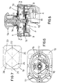
- figure 5 is a longitudinal sectioned view of the separate control according to the invention;
- figure 6 is a section view taken along the line V-V in fig.5, and
- figure 7 is a plan view of a component part of the separate control, visible in section in figure 5.
-
- With reference to the figures,
reference number 1 indicates the envelope of the separate control with a snap mountedbottom 3 and includingelectrical contacts 4. Acontrol lever 5 resting on a fulcrum on theenvelope 1, is adapted, when inclined on a side, to move abond 7 with a pair ofpin contacts 9. Thelever 5 is kept in a vertical position because its lower edge is provided by a retractablerounded point 10 which is pushed by a pressure spring into aconic notch 11, made in thebottom 3 at the vertical axis of theenvelope 1. - A side push on the
knob 13 of thelever 5, allows the lever to be inclined in an unstable position, with a rotation around thepoint 14 located at the wall of thecover 1, and thepoint 10 to slide on the surface of thenotch 11. - This inclination makes the
contacts 9 of thebond 7 translate on a printedcircuit 15, contained in theenvelope 1 and close, accordingly, the electrical circuit corresponding to one of the motors of the power window (not shown). The inclination of the lever in the opposite direction makes the window move in the opposite direction. When theknob 13 is released, thelever 5 goes back to the vertical position, pushed by thepoint 10 which slides on theinclined wall 11, thus reopening the circuit closed by the previous displacement. - Besides, the
lever 5 may be snap rotated into six selection positions, that is a neutral position, a position of simultaneous control of the four motors of the power windows, and a control position for each of the motors. - This is achieved by means of a release control integrally located rotatably to the
lever 5 above the printedcircuit 9. It is made of anarch support 16 provided with two diametricallyopposite caps 17, stressed into diametral expansion by aspring 18. Thecaps 17 can slide on the inner surface of aring guide 19, with a basically rectangular plan, the hole of which presents tworecesses knob 13 causes the rotation of thesupport 16 that drags thecaps 17. They end snap positioned into two of the facing recesses made on the inner wall of the ring. In this way at least six precise angular positions of thelever 5 in relationship to the printed circuit are realised, and one, none or more than one electrical circuits of the motors of the power windows are selected so that it is possible to act on them in order to lift or lower the respective window, by means of the inclination of the lever as it was previously described. The printed circuit will be made in a such a way that it is possible not only to act on the motors separately but to have a neutral position and a position in which more than one motor, and preferably all of them, are controlled simultaneously. - Figures 1 to 4 show a possible location of the separate control on a part of the inner covering of the
passenger compartment 30, more in particular on the dashboard or on the central tunnel between the seats. - The covering 30 forms a
cup 31 in which the upper part of thelever 5 protrudes with thecontrol knob 13. On the other hand theenvelope 1 with thebottom 3 is hidden in the part under thecup 31. The wall of the covering 30 forms, on the edge of thecup 31, aradial projection 32 protruding towards the centre of the cup, till it covers part of thecontrol knob 13. On the upper surface of the knob there are twoposition marks -
References marks 35 are present also on the inner wall of the cup, in order to indicate the position of the main axis (neutral or all) and the two diagonals (right, left). - The utilisation of the separate control is as follows.
- According to the window that is to be selected, the corresponding mark is placed on the reference indicated on the cup (for example front left in figure 1) and the
knob 13 is pulled in the direction of arrow A in order to lift the window or is pushed in the direction of arrow B in order to lower it. - The
projection 32 has been expressly made to prevent the knob to be accidentally pushed and moved to the right in figures 1, 2 and 3, in order to prevent the windows from being closed when it is not desired, for example to prevent children from doing that. It will be therefore recommended that the control be mounted in such a way that when the knob is moved to the right one or all the windows are lowered. - It is evident that in order to make up for variations of the functions of the knob, it will be enough to adjust the position of the
projection 31.
Claims (5)
- Separate control device to control electrical motors for the power windows of motor vehicles, comprising a control lever (5) which is elastically kept in vertical position in the body o a switch which can be inclined into diametrically opposite unstable positions and can be snap rotated into several angular positions in order to select one, none or more than one motors to be controlled, characterised in that said lever (5) can be rotated into at least six snap positions (21, 22, 23, 24, 25, 26), four of which are intended to control separately each one of the four motors, one is a neutral position and one is a position in which all the motors are simultaneously controlled.
- Device as claimed in claim 1, characterised in that the lever is provided with a control knob (13) arranged in a such a way that it axially protrudes from the bottom of a cup (31) made in the material (30) of the inner covering of the passenger compartment of the motor vehicle.
- Device as claimed in claim 2 characterised in that the upper surface of the knob (13) and the inner wall of the cup (31) are provided with reference marks (33, 34, 35) for the angular position of the knob.
- Device as claimed in claim 2 characterised in that the wall of covering (30) forms, on the edge of the cup (31), a radial projection (32) protruding towards the centre of said cup (31), till it covers part of the control knob (13).
- Device as claimed in claim 1 in which said lever (5) is associated with a support for contacts (7) the contacts of which (9) are adapted to translate, as a consequence of the inclination of the lever (5), on a printed circuit (15) in order to control the contacts related to said electrical circuits, and to a device to control its position during the rotation, consisting of a support (16) for the elastic caps (17) which slide, due to the rotation of said lever (5), on the inner surface of a ring (19) the plan of which is basically rectangular and which is contained in said envelope (1); characterised in that said inner surface of the ring (19) is provided with at least six recesses (21, 22, 23, 24, 25, 26) facing two by two, arranged at the main axis and the diagonal of the ring, and shaped in a way adapted to constitute at least six snap lock positions of said caps (17).
Applications Claiming Priority (2)
| Application Number | Priority Date | Filing Date | Title |
|---|---|---|---|
| ITTO980965 | 1998-11-17 | ||
| ITTO980965 IT1305185B1 (en) | 1998-11-17 | 1998-11-17 | COMMAND FOR THE ELECTRIC WINDOWS OF A VEHICLE. |
Publications (2)
| Publication Number | Publication Date |
|---|---|
| EP1003189A2 true EP1003189A2 (en) | 2000-05-24 |
| EP1003189A3 EP1003189A3 (en) | 2002-10-02 |
Family
ID=11417186
Family Applications (1)
| Application Number | Title | Priority Date | Filing Date |
|---|---|---|---|
| EP99121817A Withdrawn EP1003189A3 (en) | 1998-11-17 | 1999-11-04 | Power window control for motor vehicles |
Country Status (2)
| Country | Link |
|---|---|
| EP (1) | EP1003189A3 (en) |
| IT (1) | IT1305185B1 (en) |
Cited By (2)
| Publication number | Priority date | Publication date | Assignee | Title |
|---|---|---|---|---|
| FR2828707A1 (en) * | 2001-08-14 | 2003-02-21 | Renault | Car electric windows opening/closing control mechanism having control system distinct switch electric window group controlling and unit activating localised window selection. |
| WO2003055722A1 (en) * | 2001-12-31 | 2003-07-10 | Lear Automotive (Eeds) Spain, S.L. | Communication circuit and a control switch for vehicle window-opening mechanisms |
Citations (7)
| Publication number | Priority date | Publication date | Assignee | Title |
|---|---|---|---|---|
| US4330694A (en) * | 1979-11-05 | 1982-05-18 | Kabushiki Kaisha Tokai Rika Denki Seisakusho | Complex switch assembly |
| DE3524439A1 (en) * | 1985-07-09 | 1987-01-22 | Kirsten Elektrotech | Switch for adjusting at least two mirrors of a motor vehicle |
| US4894650A (en) * | 1987-06-27 | 1990-01-16 | Daimler-Benz Ag | Control unit for manually controlling reversible electromechanical adjusting devices |
| EP0400633A2 (en) * | 1989-05-30 | 1990-12-05 | Ichikoh Industries Limited | Remote control switch for posture adjustment of automotive mirrors |
| US5233228A (en) * | 1990-03-17 | 1993-08-03 | Mercedes Benz Ag | Control device for the manual adjustment of reversible electrical adjusting devices |
| FR2731090A1 (en) * | 1995-02-23 | 1996-08-30 | Peugeot | Multi-function actuator for controls in motor vehicle, e.g. for controlling radio functions or rear-view mirror position |
| US5621196A (en) * | 1994-08-26 | 1997-04-15 | Alps Electric Co., Ltd. | Rotary operation switch and multidirection input apparatus |
-
1998
- 1998-11-17 IT ITTO980965 patent/IT1305185B1/en active
-
1999
- 1999-11-04 EP EP99121817A patent/EP1003189A3/en not_active Withdrawn
Patent Citations (7)
| Publication number | Priority date | Publication date | Assignee | Title |
|---|---|---|---|---|
| US4330694A (en) * | 1979-11-05 | 1982-05-18 | Kabushiki Kaisha Tokai Rika Denki Seisakusho | Complex switch assembly |
| DE3524439A1 (en) * | 1985-07-09 | 1987-01-22 | Kirsten Elektrotech | Switch for adjusting at least two mirrors of a motor vehicle |
| US4894650A (en) * | 1987-06-27 | 1990-01-16 | Daimler-Benz Ag | Control unit for manually controlling reversible electromechanical adjusting devices |
| EP0400633A2 (en) * | 1989-05-30 | 1990-12-05 | Ichikoh Industries Limited | Remote control switch for posture adjustment of automotive mirrors |
| US5233228A (en) * | 1990-03-17 | 1993-08-03 | Mercedes Benz Ag | Control device for the manual adjustment of reversible electrical adjusting devices |
| US5621196A (en) * | 1994-08-26 | 1997-04-15 | Alps Electric Co., Ltd. | Rotary operation switch and multidirection input apparatus |
| FR2731090A1 (en) * | 1995-02-23 | 1996-08-30 | Peugeot | Multi-function actuator for controls in motor vehicle, e.g. for controlling radio functions or rear-view mirror position |
Cited By (2)
| Publication number | Priority date | Publication date | Assignee | Title |
|---|---|---|---|---|
| FR2828707A1 (en) * | 2001-08-14 | 2003-02-21 | Renault | Car electric windows opening/closing control mechanism having control system distinct switch electric window group controlling and unit activating localised window selection. |
| WO2003055722A1 (en) * | 2001-12-31 | 2003-07-10 | Lear Automotive (Eeds) Spain, S.L. | Communication circuit and a control switch for vehicle window-opening mechanisms |
Also Published As
| Publication number | Publication date |
|---|---|
| IT1305185B1 (en) | 2001-04-10 |
| EP1003189A3 (en) | 2002-10-02 |
| ITTO980965A1 (en) | 2000-05-17 |
Similar Documents
| Publication | Publication Date | Title |
|---|---|---|
| EP0537718B1 (en) | Armrest for a vehicle | |
| US5161422A (en) | Universal control for electrically controlled vehicle transmission | |
| EP1000834B1 (en) | Steering wheel with actuating switches | |
| EP2216201B1 (en) | Power seat control unit | |
| US6904995B2 (en) | Arrangement of operator control elements | |
| US6833517B2 (en) | Multiple switch device | |
| US20010052715A1 (en) | Control panel for a vehicle | |
| KR100962157B1 (en) | Interface device | |
| US5508897A (en) | Overhead lamp assembly | |
| US5777394A (en) | Seat adjusting switch particularly for vehicle seats | |
| US20040244524A1 (en) | Electronically actuated shifter mechanism | |
| EP0200247A2 (en) | Electric device for rapidly lighting cigars or cigarettes, particularly for motor vehicles | |
| EP1003189A2 (en) | Power window control for motor vehicles | |
| US6538220B2 (en) | Switch pod assembly | |
| US20080012413A1 (en) | Seat Adjustment Mechanism Comprising a Rotative Actuating Element | |
| US6150620A (en) | Steering column switch for a motor vehicle | |
| US6601905B1 (en) | Convertible power top and power window switch | |
| JP2001508581A (en) | Vehicle column mounting switch assembly | |
| US6555769B2 (en) | Key-type control device | |
| EP1340647B1 (en) | Manual control for the regulation of the position of a seat | |
| RU2640373C2 (en) | Vehicle armrest | |
| US6121558A (en) | Steering column switch | |
| JPS6337325Y2 (en) | ||
| KR0136327Y1 (en) | Electric column tilt switch of a vehicle | |
| EP1762422A1 (en) | Switch arrangement |
Legal Events
| Date | Code | Title | Description |
|---|---|---|---|
| PUAI | Public reference made under article 153(3) epc to a published international application that has entered the european phase |
Free format text: ORIGINAL CODE: 0009012 |
|
| AK | Designated contracting states |
Kind code of ref document: A2 Designated state(s): AT BE CH CY DE DK ES FI FR GB GR IE IT LI LU MC NL PT SE |
|
| AX | Request for extension of the european patent |
Free format text: AL;LT;LV;MK;RO;SI |
|
| RAP3 | Party data changed (applicant data changed or rights of an application transferred) |
Owner name: BITRON S.P.A. |
|
| PUAL | Search report despatched |
Free format text: ORIGINAL CODE: 0009013 |
|
| AK | Designated contracting states |
Kind code of ref document: A3 Designated state(s): AT BE CH CY DE DK ES FI FR GB GR IE IT LI LU MC NL PT SE |
|
| AX | Request for extension of the european patent |
Free format text: AL;LT;LV;MK;RO;SI |
|
| STAA | Information on the status of an ep patent application or granted ep patent |
Free format text: STATUS: THE APPLICATION IS DEEMED TO BE WITHDRAWN |
|
| 18D | Application deemed to be withdrawn |
Effective date: 20011201 |