EP1002949A2 - Vertical axis wind turbine - Google Patents
Vertical axis wind turbine Download PDFInfo
- Publication number
- EP1002949A2 EP1002949A2 EP99118279A EP99118279A EP1002949A2 EP 1002949 A2 EP1002949 A2 EP 1002949A2 EP 99118279 A EP99118279 A EP 99118279A EP 99118279 A EP99118279 A EP 99118279A EP 1002949 A2 EP1002949 A2 EP 1002949A2
- Authority
- EP
- European Patent Office
- Prior art keywords
- rotor
- power plant
- wind power
- wind
- bearing
- Prior art date
- Legal status (The legal status is an assumption and is not a legal conclusion. Google has not performed a legal analysis and makes no representation as to the accuracy of the status listed.)
- Withdrawn
Links
- 230000005540 biological transmission Effects 0.000 claims description 11
- 238000005253 cladding Methods 0.000 claims description 8
- 230000000694 effects Effects 0.000 claims description 3
- 239000007788 liquid Substances 0.000 claims description 3
- 230000001681 protective effect Effects 0.000 claims description 2
- 239000002131 composite material Substances 0.000 claims 1
- 229910052751 metal Inorganic materials 0.000 claims 1
- 239000002184 metal Substances 0.000 claims 1
- 150000002739 metals Chemical class 0.000 claims 1
- 229920003023 plastic Polymers 0.000 claims 1
- 239000004033 plastic Substances 0.000 claims 1
- 230000014616 translation Effects 0.000 claims 1
- 238000013519 translation Methods 0.000 claims 1
- 238000009420 retrofitting Methods 0.000 description 2
- 230000003068 static effect Effects 0.000 description 2
- 208000012886 Vertigo Diseases 0.000 description 1
- 230000015572 biosynthetic process Effects 0.000 description 1
- 230000005611 electricity Effects 0.000 description 1
- 230000003993 interaction Effects 0.000 description 1
- 230000011218 segmentation Effects 0.000 description 1
- 230000007306 turnover Effects 0.000 description 1
Images


Classifications
-
- F—MECHANICAL ENGINEERING; LIGHTING; HEATING; WEAPONS; BLASTING
- F03—MACHINES OR ENGINES FOR LIQUIDS; WIND, SPRING, OR WEIGHT MOTORS; PRODUCING MECHANICAL POWER OR A REACTIVE PROPULSIVE THRUST, NOT OTHERWISE PROVIDED FOR
- F03D—WIND MOTORS
- F03D1/00—Wind motors with rotation axis substantially parallel to the air flow entering the rotor
- F03D1/02—Wind motors with rotation axis substantially parallel to the air flow entering the rotor having a plurality of rotors
-
- F—MECHANICAL ENGINEERING; LIGHTING; HEATING; WEAPONS; BLASTING
- F03—MACHINES OR ENGINES FOR LIQUIDS; WIND, SPRING, OR WEIGHT MOTORS; PRODUCING MECHANICAL POWER OR A REACTIVE PROPULSIVE THRUST, NOT OTHERWISE PROVIDED FOR
- F03D—WIND MOTORS
- F03D15/00—Transmission of mechanical power
- F03D15/10—Transmission of mechanical power using gearing not limited to rotary motion, e.g. with oscillating or reciprocating members
-
- F—MECHANICAL ENGINEERING; LIGHTING; HEATING; WEAPONS; BLASTING
- F03—MACHINES OR ENGINES FOR LIQUIDS; WIND, SPRING, OR WEIGHT MOTORS; PRODUCING MECHANICAL POWER OR A REACTIVE PROPULSIVE THRUST, NOT OTHERWISE PROVIDED FOR
- F03D—WIND MOTORS
- F03D3/00—Wind motors with rotation axis substantially perpendicular to the air flow entering the rotor
- F03D3/02—Wind motors with rotation axis substantially perpendicular to the air flow entering the rotor having a plurality of rotors
-
- F—MECHANICAL ENGINEERING; LIGHTING; HEATING; WEAPONS; BLASTING
- F03—MACHINES OR ENGINES FOR LIQUIDS; WIND, SPRING, OR WEIGHT MOTORS; PRODUCING MECHANICAL POWER OR A REACTIVE PROPULSIVE THRUST, NOT OTHERWISE PROVIDED FOR
- F03D—WIND MOTORS
- F03D3/00—Wind motors with rotation axis substantially perpendicular to the air flow entering the rotor
- F03D3/04—Wind motors with rotation axis substantially perpendicular to the air flow entering the rotor having stationary wind-guiding means, e.g. with shrouds or channels
- F03D3/0436—Wind motors with rotation axis substantially perpendicular to the air flow entering the rotor having stationary wind-guiding means, e.g. with shrouds or channels for shielding one side of the rotor
- F03D3/0472—Wind motors with rotation axis substantially perpendicular to the air flow entering the rotor having stationary wind-guiding means, e.g. with shrouds or channels for shielding one side of the rotor the shield orientation being adaptable to the wind motor
- F03D3/049—Wind motors with rotation axis substantially perpendicular to the air flow entering the rotor having stationary wind-guiding means, e.g. with shrouds or channels for shielding one side of the rotor the shield orientation being adaptable to the wind motor with converging inlets, i.e. the shield intercepting an area greater than the effective rotor area
-
- F—MECHANICAL ENGINEERING; LIGHTING; HEATING; WEAPONS; BLASTING
- F03—MACHINES OR ENGINES FOR LIQUIDS; WIND, SPRING, OR WEIGHT MOTORS; PRODUCING MECHANICAL POWER OR A REACTIVE PROPULSIVE THRUST, NOT OTHERWISE PROVIDED FOR
- F03D—WIND MOTORS
- F03D80/00—Details, components or accessories not provided for in groups F03D1/00 - F03D17/00
- F03D80/70—Bearing or lubricating arrangements
-
- F—MECHANICAL ENGINEERING; LIGHTING; HEATING; WEAPONS; BLASTING
- F03—MACHINES OR ENGINES FOR LIQUIDS; WIND, SPRING, OR WEIGHT MOTORS; PRODUCING MECHANICAL POWER OR A REACTIVE PROPULSIVE THRUST, NOT OTHERWISE PROVIDED FOR
- F03D—WIND MOTORS
- F03D9/00—Adaptations of wind motors for special use; Combinations of wind motors with apparatus driven thereby; Wind motors specially adapted for installation in particular locations
- F03D9/20—Wind motors characterised by the driven apparatus
- F03D9/25—Wind motors characterised by the driven apparatus the apparatus being an electrical generator
-
- F—MECHANICAL ENGINEERING; LIGHTING; HEATING; WEAPONS; BLASTING
- F05—INDEXING SCHEMES RELATING TO ENGINES OR PUMPS IN VARIOUS SUBCLASSES OF CLASSES F01-F04
- F05B—INDEXING SCHEME RELATING TO WIND, SPRING, WEIGHT, INERTIA OR LIKE MOTORS, TO MACHINES OR ENGINES FOR LIQUIDS COVERED BY SUBCLASSES F03B, F03D AND F03G
- F05B2240/00—Components
- F05B2240/90—Mounting on supporting structures or systems
- F05B2240/91—Mounting on supporting structures or systems on a stationary structure
- F05B2240/911—Mounting on supporting structures or systems on a stationary structure already existing for a prior purpose
-
- Y—GENERAL TAGGING OF NEW TECHNOLOGICAL DEVELOPMENTS; GENERAL TAGGING OF CROSS-SECTIONAL TECHNOLOGIES SPANNING OVER SEVERAL SECTIONS OF THE IPC; TECHNICAL SUBJECTS COVERED BY FORMER USPC CROSS-REFERENCE ART COLLECTIONS [XRACs] AND DIGESTS
- Y02—TECHNOLOGIES OR APPLICATIONS FOR MITIGATION OR ADAPTATION AGAINST CLIMATE CHANGE
- Y02E—REDUCTION OF GREENHOUSE GAS [GHG] EMISSIONS, RELATED TO ENERGY GENERATION, TRANSMISSION OR DISTRIBUTION
- Y02E10/00—Energy generation through renewable energy sources
- Y02E10/70—Wind energy
- Y02E10/72—Wind turbines with rotation axis in wind direction
-
- Y—GENERAL TAGGING OF NEW TECHNOLOGICAL DEVELOPMENTS; GENERAL TAGGING OF CROSS-SECTIONAL TECHNOLOGIES SPANNING OVER SEVERAL SECTIONS OF THE IPC; TECHNICAL SUBJECTS COVERED BY FORMER USPC CROSS-REFERENCE ART COLLECTIONS [XRACs] AND DIGESTS
- Y02—TECHNOLOGIES OR APPLICATIONS FOR MITIGATION OR ADAPTATION AGAINST CLIMATE CHANGE
- Y02E—REDUCTION OF GREENHOUSE GAS [GHG] EMISSIONS, RELATED TO ENERGY GENERATION, TRANSMISSION OR DISTRIBUTION
- Y02E10/00—Energy generation through renewable energy sources
- Y02E10/70—Wind energy
- Y02E10/728—Onshore wind turbines
-
- Y—GENERAL TAGGING OF NEW TECHNOLOGICAL DEVELOPMENTS; GENERAL TAGGING OF CROSS-SECTIONAL TECHNOLOGIES SPANNING OVER SEVERAL SECTIONS OF THE IPC; TECHNICAL SUBJECTS COVERED BY FORMER USPC CROSS-REFERENCE ART COLLECTIONS [XRACs] AND DIGESTS
- Y02—TECHNOLOGIES OR APPLICATIONS FOR MITIGATION OR ADAPTATION AGAINST CLIMATE CHANGE
- Y02E—REDUCTION OF GREENHOUSE GAS [GHG] EMISSIONS, RELATED TO ENERGY GENERATION, TRANSMISSION OR DISTRIBUTION
- Y02E10/00—Energy generation through renewable energy sources
- Y02E10/70—Wind energy
- Y02E10/74—Wind turbines with rotation axis perpendicular to the wind direction
-
- Y—GENERAL TAGGING OF NEW TECHNOLOGICAL DEVELOPMENTS; GENERAL TAGGING OF CROSS-SECTIONAL TECHNOLOGIES SPANNING OVER SEVERAL SECTIONS OF THE IPC; TECHNICAL SUBJECTS COVERED BY FORMER USPC CROSS-REFERENCE ART COLLECTIONS [XRACs] AND DIGESTS
- Y10—TECHNICAL SUBJECTS COVERED BY FORMER USPC
- Y10S—TECHNICAL SUBJECTS COVERED BY FORMER USPC CROSS-REFERENCE ART COLLECTIONS [XRACs] AND DIGESTS
- Y10S415/00—Rotary kinetic fluid motors or pumps
- Y10S415/905—Natural fluid current motor
- Y10S415/908—Axial flow runner
Definitions
- the invention relates to a wind turbine with a horizontal rotating rotor, as well as a rotor for this horizontally rotating wind turbine that a variety of rotor blades and connected to a generator is.
- GB 20414587 A describes a vertical axis known rotating wind turbine, the areas of a housing is surrounded.
- the housing is shaped by a wind vane Aligned in the wind so that the opposing wind Rotor blades are protected.
- a wind power plant is known from DD 296 734 rotates about a vertical axis, the impeller by a Protective shield in the shape of a segment of a circle, which surrounds itself the axis of the impeller rotates.
- DE 38 29 112 describes a wind turbine with a Known rotor blades equipped with a generator connected, and which is encapsulated by a housing that can be freely aligned in the desired wind direction.
- the housing has a funnel-shaped inlet, which is provided with air baffles. Through an air outlet, the smaller is designed to accelerate the air.
- the inflow funnel is aligned against the wind.
- a wheel-shaped wind turbine is known from DE 196 48 632, whose rotor has a plurality of trough-shaped rotor blades has, the wind turbine surrounded by a housing is constructed like the housing of the wind turbine, the is known from the publication DE 38 29 112.
- the object of the present invention is a wind turbine to provide, which has a high efficiency and which is easy to install and with existing ones Wind turbines can be combined. It should also be possible be to expand the system as needed without major to meet technical and financial expenses. Another The task is to simply attach the device on existing towers. Another task is the unpleasant shadow formation of the conventional To avoid wind turbines. There is still another task in, for this device one yourself in the horizontal provide rotating rotor, the optimal aerodynamic Has properties around the air resistance of the flowing back To minimize air.
- the rotor blades are completely surrounded by a fairing, the cover having an air inlet and an air outlet has, and the cladding depending on the wind direction Alignment means is aligned so that the air intake is optimal is directed against the wind direction.
- the cladding is rotatably supported and is supported by a wind vane-shaped fairing aligner aligned.
- the paneling is made by aligned a servomotor that is controlled by a wind sensor becomes.
- the wind turbine has means for subsequent attachment on existing masts.
- This wind turbine consists of a rotating in the horizontal direction annular rotor which has a plurality of rotor blades.
- the wind turbine also includes an annular one Bearing ring on which the rotor rotates on bearings, whereby the bearing ring extends around the mast and the bearings through Connection struts are attached to the mast.
- a reversal this principle is also conceivable, so that the bearing ring is static and the rotor is connected to bearings that are on the Run the bearing ring.
- the connecting struts are designed so that they are different strong masts can be attached variable without making significant design changes have to.
- the rotor is connected to a generator via a gear connected.
- the rotor is on its inside facing the mast gear-shaped, being in this first Gear
- a second gear that engages via a gear shaft is connected to the generator.
- the power transmission takes place in a further embodiment by means of a friction drive, which is connected via a belt and if necessary Transmission transmits the power to the generator.
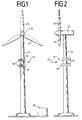
- FIG. 1 shows a wind turbine 23, on the mast 25 of which several wind turbines 10 according to the invention are attached.
- the wind turbines 10 according to the invention are horizontal arranged one above the other.
- the wind turbines according to the invention 10 are preferably below the vertically rotating Fixed rotor 24 to avoid wind turbulence.
- the wind turbines according to the invention consist of a annular rotor 17, as can be seen in Figures 3 and 5 is protected by a panel around the mast 25 turns. It can be seen from FIG. 1 that the paneling has a Has funnel-shaped air inlet that faces the wind becomes.
- the electricity generated by the wind turbines is in a transformer 26 that is regularly on the ground is arranged, converted to the required voltage and frequency.
- Figure 2 shows a side view of the device of the figure 1. This view shows a panel alignment 16 visible, the wind-controlled cladding like a flag 15 aligns.
- FIG. 3 is a detailed structure of the wind turbine 10 remove.
- This has the rotor 17, which is annular is so that it can rotate around the mast 25.
- At the Rotor blades 11 are attached to the outside of the rotor 17 are preferably spoon-shaped. Other forms are but also conceivable.
- Half of the rotor 17 is from the Surrounding 15, which is preferably a U-shaped Has cross section.
- the casing 15 is also rotatable stored and aligned depending on the wind direction 21 so that the rotor blades 11 which are opposed to the wind are protected.
- a possible storage of the cladding is shown in FIG. 9 remove.
- the panel 21 is preferably by a correspondingly large panel aligner 16, that looks like a flag.
- the Fairing aligner 16 is preferably on the rear Edge and the side of the panel 15 facing away from the wind attached.
- Figure 5 is another way of training the Remove panel 15.
- the rotor 17 becomes almost completely surrounded by the fairing.
- the panel points only one air inlet 28 through the above Medium is always aligned against the wind, and so arranged is that the wind directly into the rotor blades 11 of the Rotors 17 engages.
- the panel also has an air outlet 29 on.
- the panel 15 thus creates a pump or.
- the air inlet 28 is preferably funnel-shaped and has Air baffles 30 on the wind in the most optimal deflect as the rotor blades 11. Depending on the arrangement of the The wind should be redirected in the direction of rotation become. If the funnel as in the present case is arranged laterally, so the setting angle changes Air baffles 30 the closer they are to the center of the rotor 17 are.
- the Bearing consists of an L-shaped bearing ring 12 on which the rotor 17 is attached. Between the legs of the bearing ring 12 are bearings 27 arranged in the form of impellers in one oblique angles are arranged between the legs.
- the figure also shows the arrangement of a generator 19, the one without gear, directly via a friction wheel drive 31 is connected to the rotor 17.
- the rotor 17 is on an L-shaped Fixed bearing ring 12 which extends around the mast 25. Extend radially at an equiangular distance the mast 25 bearing 27, which are arranged on connecting struts 13 are.
- the bearings 27 are preferably at an angle of Arranged 45 ° and extend with their outer tread in the angle through the apex of the bearing ring 12 is formed.
- the bearing 27 is preferably an impeller educated.
- the connecting struts 13 are opposite to the bearing 27 Side connected to the mast 25.
- the arrangement of the generator 19 can also be seen in FIG. This is preferably arranged hanging under the rotor 17.
- the rotor 17 is through the L-shaped bearing ring a friction wheel drive 31, which is shown in more detail in FIG is connected to the generator 19.
- a gear shaft 20 of the generator 19 is either direct or via a gear 18 connected to a friction wheel 33.
- the friction wheel 33 will by a tensioning wheel 34 against the preferably the vertical Leg of the L-shaped bearing rings 12 pressed.
- the generator 19 is also through a connecting strut 13 to the mast 25 connected. Depending on the speed of the rotor 17, this can Friction wheel to be put on or not.
- the rotor 17 start rotating slightly without contact with the generator To have 19.
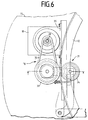
- FIG. 6 shows the detailed structure of the friction wheel drive 31 remove.
- the generator 19 is the friction wheel 33 and the Tensioning wheel 34 arranged on a frame 35, which in turn over a connecting strut 13 is connected to the mast 25.
- the friction wheel 33 is connected to the transmission shaft 20 via a belt 32 of the generator 19 connected. This allows certain gear ratios be predetermined.
- the friction wheel 33 will by spring force against the vertical leg of the L-shaped Bearing rings 12 pressed. To a corresponding friction wheel too will have the tension wheel 34 on the opposite side of the leg pressed with a spring against the friction wheel 33. This creates a pressure on both sides of the leg exercised, which enables a power transmission without friction losses.
- gears are also conceivable. So could well-known automatic transmissions are used which the generator always keep at an optimal number of revolutions. The These gears are controlled depending on the rotation of the rotor.
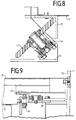
- the drive is shown in side view in FIG.
- the generator 19 is directly over its gear shaft 20 connected to the friction wheel.
- the tensioning wheel 34 is arranged so that pressure from both sides one leg is exerted on the vertical leg becomes.
- the friction wheels are preferably ball mounted.
- the Bearing ring formed in its inside gear-shaped to to drive a second gear.
- the second gear is e.g. connected to the generator 19 via a gear shaft 20.
- the generator 19 could also be integrated directly in the rotor 17 be so that the rotor 17 and the bearing ring 12 in interaction have the effect of a generator.
- Figure 8 is a detailed view of the storage.
- Bearing 27 shaped as a wheel, the axis of which at an angle of 45 ° is arranged.
- the wheel is supported on two ball bearings, which are arranged in a housing which is mounted on a frame 36 is attached.
- the frame 36 is in turn with a connecting strut 13 connected.
- the tread of the wheel is preferred trending so that the treads in the angle formed by the legs of the L-shaped bearing ring fit snugly.
- Figure 9 shows the storage of the fairing 15 on the rotor 17.
- two ball bearings 38, 39 at an angle of 90 ° to each other, each on the leg of an also L-shaped bearing ring 37.
- Camps 38, 39 are attached to the panel 15. That kind of Storage is multiple on the rotor 17 in orbit Lagerings 37 arranged, which is connected to the panel 15 is.
- the housing can also be supported as shown in the figure 4 can be removed.
- both the rotor 17 and the bearing ring 12 are divisible so that they can be guided around an existing mast 25.
- the division preferably takes place in segments of the same size.
- variable connecting struts 13 connect the bearings 27 to the mast 25. They can be different Lengths to match the differing mast thicknesses To take into account.
- the retrofitted wind turbine can already do one use existing transformer 26 to recover the Feed energy into the public grid.
Abstract
Description
Die Erfindung betrifft eine Windkraftanlage mit einem sich in horizontaler Richtung drehenden Rotor, sowie einen Rotor für diese sich horizontal drehende Windkraftanlage, der eine Vielzahl von Rotorblättern aufweist und mit einem Generator verbunden ist.The invention relates to a wind turbine with a horizontal rotating rotor, as well as a rotor for this horizontally rotating wind turbine that a variety of rotor blades and connected to a generator is.
Bekannte Windkraftanlagen sind auf hohen Masten angeordnet, um ihre großen Rotoren ausreichend gegen den Wind zu richten. Die Rotoren sind hierbei vertikal ausgerichtet und drehen sich um eine horizontale Achse. Die vertikale Achse ist dabei in der Regel mit einem Generator verbunden. Durch die vertikale Anordnung können jedoch insbesondere bei ungünstigem Lichteinfall unangenehme Schattenbildungen entstehen. Weiterhin sind enorm hohe Masten notwendig, um eine ausreichende Leistung zu garantieren. Die schweren Getriebe, über die die Rotoren mit dem Generator verbunden sind, führen oftmals zu statischen Problemen der Türme. Bei starken Winden werden enorme Kräfte auf den Mast ausgeübt, die zu einem Bruch führen können.Known wind turbines are arranged around high masts to direct their large rotors against the wind. The Rotors are aligned vertically and turn around a horizontal axis. The vertical axis is in the Usually connected to a generator. Due to the vertical arrangement can, however, especially in the case of unfavorable light unpleasant shadows form. Furthermore are enormously high masts necessary to achieve sufficient performance to guarantee. The heavy gears that the rotors use connected to the generator often lead to static Problems of the towers. With strong winds there are enormous forces exerted on the mast, which can lead to breakage.
Aus der GB 20414587 A ist ein sich um eine vertikale Achse drehendes Windrad bekannt, das bereichsweise von einem Gehäuse umgeben ist. Das Gehäuse wird durch einen windfahnenförmigen Ausrichter so in den Wind gestellt, das die dem Wind gegenläufigen Rotorblätter geschützt sind. GB 20414587 A describes a vertical axis known rotating wind turbine, the areas of a housing is surrounded. The housing is shaped by a wind vane Aligned in the wind so that the opposing wind Rotor blades are protected.
Aus der DE 26 20 862 ist eine Windkraftanlage bekannt, deren sich um eine horizontale Achse drehenden Rotoren durch einen Klemmrahmen um einen Mast befestigt sind. Hierbei sind, je zwei Rotoren rechts und links vom Mast befestigt und werden durch den Klemmrahmen, der drehbar um den Mast gelagert ist, gegen den Wind ausgerichtet.From DE 26 20 862 a wind turbine is known, the rotors rotating around a horizontal axis by a Clamping frames are attached to a mast. Here, each two rotors are attached to the right and left of the mast through the clamping frame, which is rotatably mounted around the mast, aligned against the wind.
Aus der DD 296 734 ist eine Windkraftanlage bekannt, die sich um eine vertikale Achse dreht, wobei das Flügelrad durch ein kreissegmentförmiges Schutzschild umgeben ist, das sich um die Achse des Flügelrades dreht.A wind power plant is known from DD 296 734 rotates about a vertical axis, the impeller by a Protective shield in the shape of a segment of a circle, which surrounds itself the axis of the impeller rotates.
Aus der DE 196 15 943 ist eine Solaranlage bekannt, die je nach Bedarf aus einer Vielzahl von genormten Modulen aufgebaut werden kann, wobei die Module sowohl herkömmliche Solarmodule als auch herkömmliche Windkraftanlagen sind, die sich um eine horizontale Achse drehen.From DE 196 15 943 a solar system is known, each built from a variety of standardized modules as required can be, the modules both conventional solar modules as well as conventional wind turbines that are rotate around a horizontal axis.
Aus der DE 38 29 112 ist eine Windkraftanlage mit einem mit Schaufeln bestücktem Rotor bekannt, der mit einem Generator verbunden ist, und der durch eine Gehäuse gekapselt ist, das sich frei in die gewünschte Windrichtung ausrichten läßt. Hierbei weist das Gehäuse einen trichterförmigen Einlaß auf, der mit Luftleitblechen versehen ist. Durch einen Luftauslaß, der kleiner gestaltet ist, soll die Luft beschleunigt werden. Der Einströmtrichter wird gegen den Wind ausgerichtet.DE 38 29 112 describes a wind turbine with a Known rotor blades equipped with a generator connected, and which is encapsulated by a housing that can be freely aligned in the desired wind direction. Here, the housing has a funnel-shaped inlet, which is provided with air baffles. Through an air outlet, the smaller is designed to accelerate the air. The inflow funnel is aligned against the wind.
Aus der DE 196 48 632 ist eine radförmige Windkraftanlage bekannt,
dessen Rotor eine Vielzahl von wannenförmigen Rotorblättern
aufweist, wobei das Windrad von einem Gehäuse umgeben
ist, das so aufgebaut ist wie das Gehäuse des Windrades, das
aus der Druckschrift DE 38 29 112 bekannt ist.A wheel-shaped wind turbine is known from DE 196 48 632,
whose rotor has a plurality of trough-shaped rotor blades
has, the wind turbine surrounded by a housing
is constructed like the housing of the wind turbine, the
is known from the
Aufgabe der vorliegenden Erfindung ist es, eine Windkraftanlage bereitzustellen, die einen hohen Wirkungsgrad aufweist und die einfach zu installieren ist, sowie mit bereits bestehenden Windkraftanlagen kombiniert werden kann. Ferner soll es möglich sein, die Anlage je nach Bedarf auszubauen, ohne große technische und finanzielle Aufwendungen zu treffen. Eine weitere Aufgabe besteht in der einfachen Befestigung der Vorrichtung an bereits bestehenden Türmen. Noch eine weitere Aufgabe besteht darin, die unangenehme Schattenbildung der herkömmlichen Windräder zu vermeiden. Noch eine weitere Aufgabe besteht darin, für diese Vorrichtung einen sich in der horizontalen drehenden Rotor bereitzustellen, der optimale aerodynamische Eigenschaften aufweist um den Luftwiderstand der zurückströmenden Luft zu minimieren.The object of the present invention is a wind turbine to provide, which has a high efficiency and which is easy to install and with existing ones Wind turbines can be combined. It should also be possible be to expand the system as needed without major to meet technical and financial expenses. Another The task is to simply attach the device on existing towers. Another task is the unpleasant shadow formation of the conventional To avoid wind turbines. There is still another task in, for this device one yourself in the horizontal provide rotating rotor, the optimal aerodynamic Has properties around the air resistance of the flowing back To minimize air.
Gelöst wird diese Aufgabe, durch die Merkmale der Ansprüche 1,
3, 9 und 20, insbesondere durch einen Rotor für eine sich horizontal
drehende Windkraftanlage, der eine Vielzahl von Rotorblättern
aufweist und mit einem Generator verbunden ist,
wobei die Rotorblätter bereichsweise von einer Verkleidung umgeben
sind, wobei die Verkleidung je nach Windrichtung durch
Ausrichtmittel so ausrichtet wird, daß immer die der Windrichtung
gegenläufigen Rotorblätter geschützt sind.This object is achieved by the features of
Um eine hohe Effektivität sicher zu stellen, umgibt und schützt die Verkleidung zumindest die Hälfte der Rotorblätter.To ensure high effectiveness, surrounds and protects the fairing at least half of the rotor blades.
In einer weiteren erfindungsgemäßen Ausgestaltung des Rotors sind die Rotorblätter von einer Verkleidung vollständig umgeben, wobei die Verkleidung einen Lufteinlaß und einen Luftauslaß aufweist, und die Verkleidung je nach Windrichtung durch Ausrichtmittel, so ausgerichtet wird, daß der Lufteinlaß optimal gegen die Windrichtung ausgerichtet wird.In a further embodiment of the rotor according to the invention the rotor blades are completely surrounded by a fairing, the cover having an air inlet and an air outlet has, and the cladding depending on the wind direction Alignment means is aligned so that the air intake is optimal is directed against the wind direction.
Hierzu ist die Verkleidung drehbar gelagert und wird durch einen windfahnenförmigen Verkleidungausrichter ausgerichtet. For this purpose, the cladding is rotatably supported and is supported by a wind vane-shaped fairing aligner aligned.
In einer weiteren Ausführungsform wird die Verkleidung durch einen Stellmotor ausgerichtet, der von einem Windsensor angesteuert wird.In a further embodiment, the paneling is made by aligned a servomotor that is controlled by a wind sensor becomes.
Um bereits bestehende Windkraftanlage sinnvoll zu erweitern, weist die Windkraftanlage Mittel zur nachträglichen Befestigung an bereits vorhandenen Masten auf. Diese Windkraftanlage besteht aus einem sich in horizontaler Richtung drehenden ringförmigen Rotor, der eine Vielzahl von Rotorblättern aufweist. Ferner beinhaltet die Windkraftanlage einen ringförmigen Lagerring, auf der sich der Rotor auf Lagern dreht, wobei sich der Lagerring um den Mast erstreckt und die Lager durch Verbindungsstreben an dem Mast befestigt sind. Eine Umkehrung diese Prinzip ist ebenfalls denkbar, so daß der Lagerring statisch ist und der Rotor mit Lagern verbunden sind, die auf dem Lagerring laufen.In order to expand existing wind turbines in a meaningful way, the wind turbine has means for subsequent attachment on existing masts. This wind turbine consists of a rotating in the horizontal direction annular rotor which has a plurality of rotor blades. The wind turbine also includes an annular one Bearing ring on which the rotor rotates on bearings, whereby the bearing ring extends around the mast and the bearings through Connection struts are attached to the mast. A reversal this principle is also conceivable, so that the bearing ring is static and the rotor is connected to bearings that are on the Run the bearing ring.
Die Verbindungsstreben sind so ausgelegt, daß sie an unterschiedlich starken Masten variable befestigt werden können, ohne dabei erhebliche konstruktive Veränderungen vornehmen zu müssen. Über ein Getriebe ist der Rotor mit einem Generator verbunden. Der Rotor ist an seiner zum Mast gerichteten Innenseite zahnradförmig ausgebildet, wobei in dieses erste Zahnrad ein zweites Zahnrad greift, das über eine Getriebewelle mit dem Generator verbunden ist.The connecting struts are designed so that they are different strong masts can be attached variable without making significant design changes have to. The rotor is connected to a generator via a gear connected. The rotor is on its inside facing the mast gear-shaped, being in this first Gear A second gear that engages via a gear shaft is connected to the generator.
In einer weiteren Ausführung erfolgt die Kraftübertragung durch einen Reibantrieb, der über einen Riemen und ggfs. ein Getriebe die Kraft an den Generator überträgt.The power transmission takes place in a further embodiment by means of a friction drive, which is connected via a belt and if necessary Transmission transmits the power to the generator.
Durch die ringförmige Ausgestaltung ist eine Befestigung an bereits bestehenden Masten oder zu installierenden Windkraftanlage ohne weiteres möglich. Insbesondere können eine Vielzahl der beschriebenen Windkraftanlagen an einem Masten übereinander befestigt werden. Auch eine gemeinsame Nutzung des Transformators bzw. der Umspannvorrichtung ist denkbar. Die Segmentierung des Rotors und des Lagerrings erlaubt eine nachträgliche Montage.Due to the ring-shaped configuration, it is attached to existing masts or wind turbines to be installed easily possible. In particular, a variety the wind turbines described above one above the other be attached. Also sharing the Transformer or the transformer device is conceivable. The Segmentation of the rotor and the bearing ring allows one retrofitting.
Weiter vorteilhafte Ausführungsformen sind in den Unteransprüchen aufgeführt. Es folgt eine detaillierte Beschreibung anhand der Zeichnungen. Es zeigt:
- Figur 1
- eine herkömmliche Windkraftanlage mit einem sich vertikal um eine horizontale Achse drehenden Rotor, an deren Mast mehrere erfindungsgemäße Windkraftanlagen befestigt sind, die sich horizontal drehen und deren vollständige Verkleidung einen Lufteinlaß aufweist;
- Figur 2
- zeigt eine Seitenansicht der in Figur 1 dargestellten Windkraftanlagen, wobei die Verkleidung durch einen windgesteuerten Gehäuseausrichter ausgerichtet wird;
-
Figur 3 - eine Draufsicht auf eine erfindungsgemäße Windkraftanlage, mit einem ringförmigen Rotor, der eine Vielzahl von Rotorblättern aufweist, wobei die Hälfte des Rotors und der Blätter von einer Verkleidung umgeben wird, die durch einen windgesteuerten Verkleidungausrichter ausgerichtet wird;
- Figur 4
- eine schematische Seitenansicht der erfindungsgemäßen Vorrichtung, die um einen Mast angeordnet ist, wobei der Rotor auf einem L-förmigen Lagerring angeordnet ist, der sich auf in einem Winkel von 45° angeordneten Lagern dreht, wobei der Rotor über ein Reibradantrieb, mit einem Generator verbunden ist;
- Figur 5
- eine schematische Draufsicht auf einen erfindungsgemäßen Rotor, der vollständig von einer Verkleidung umgeben ist, wobei die Verkleidung einen trichterförmigen Lufteinlaß aufweist, der mit Luftleitblechen versehen ist, und mit einem Luftauslaß, der mit Hilfe der Formgebung der Verkleidung so angeordnet ist, daß ein Venturi-Effekt entsteht.
- Figur 6
- eine Detailansicht des Reibradantriebes, der ein Reibrad und ein Spannrad aufweist, die an einen Schenkel des L-förmig ausgebildeten Lagerrings anliegen, wobei die Energie durch einen Riemen auf den Generator übertragen wird;
- Figur 7
- zeigt einen Schnitt entlang der Seitenansicht der Figur 6, mit dem Generator, dem Reibrad, dem Spannrad, dem L-förmigen Lagerring, auf dem der Rotor angeordnet ist;
- Figur 8
- zeigt im Detail den Schnitt entlang der Seitenansicht der Lagerung des Rotors, der auf ein L-förmigen Lagerring befestigt ist, wobei ein Lager, das in Form eines Lagerrades ausgebildet ist, im Winkel von 45° an einem stationären Rahmen befestigt ist;
- Figur 9
- zeigt die schematische Seitenansicht einer mögliche Lagerung der Verkleidung liegend auf dem Rotor, mit einem L-förmigen Lagerring, dessen Schenkel von zwei Lagern geführt werden.
- Figure 1
- a conventional wind turbine with a rotor rotating vertically about a horizontal axis, to the mast of which several wind turbines according to the invention are fastened, which rotate horizontally and whose complete covering has an air inlet;
- Figure 2
- shows a side view of the wind turbines shown in Figure 1, wherein the panel is aligned by a wind-controlled housing aligner;
- Figure 3
- a plan view of a wind turbine according to the invention, with an annular rotor having a plurality of rotor blades, wherein half of the rotor and the blades are surrounded by a casing which is aligned by a wind-controlled casing aligner;
- Figure 4
- is a schematic side view of the device according to the invention, which is arranged around a mast, the rotor being arranged on an L-shaped bearing ring which rotates on bearings arranged at an angle of 45 °, the rotor being connected to a generator via a friction wheel drive is;
- Figure 5
- a schematic plan view of a rotor according to the invention, which is completely surrounded by a casing, the casing having a funnel-shaped air inlet, which is provided with air baffles, and with an air outlet, which is arranged with the aid of the shape of the casing so that a venturi Effect arises.
- Figure 6
- a detailed view of the friction wheel drive, which has a friction wheel and a tensioning wheel, which bear against one leg of the L-shaped bearing ring, the energy being transmitted by a belt to the generator;
- Figure 7
- shows a section along the side view of Figure 6, with the generator, the friction wheel, the tensioning wheel, the L-shaped bearing ring on which the rotor is arranged;
- Figure 8
- shows in detail the section along the side view of the bearing of the rotor, which is attached to an L-shaped bearing ring, wherein a bearing, which is designed in the form of a bearing wheel, is attached at an angle of 45 ° to a stationary frame;
- Figure 9
- shows the schematic side view of a possible storage of the fairing lying on the rotor, with an L-shaped bearing ring, the legs of which are guided by two bearings.
Die Figur 1 zeigt eine Windkraftanlage 23, an deren Mast 25
mehrere erfindungsgemäße Windkraftanlagen 10 befestigt sind.
Die erfindungsgemäßen Windkraftanlagen 10 sind dabei horizontal
übereinander angeordnet. Die erfindungsgemäßen Windkraftanlagen
10 sind vorzugsweise unterhalb des sich vertikal drehenden
Rotors 24 befestigt, um Windturbulenzen zu vermeiden. FIG. 1 shows a
Die erfindungsgemäßen Windkraftanlagen bestehen aus einem
ringförmigen Rotor 17, wie er den Figuren 3 und 5 entnehmbar
ist, der sich geschützt durch eine Verkleidung um den Mast 25
dreht. Der Figur 1 ist zu entnehmen, daß die Verkleidung einen
trichterförmigen Lufteinlaß aufweist, der gegen den Wind gerichtet
wird. Der durch die Windkraftanlagen erzeugte Strom
wird in einem Transformator 26, der regelmäßig auf dem Boden
angeordnet ist, auf die benötigte Spannung und Frequenz umgewandelt.The wind turbines according to the invention consist of a
Figur 2 stellt in einer Seitenansicht die Vorrichtung der Figur
1 dar. Durch diese Ansicht wird ein Verkleidungsausrichtung
16 sichtbar, der windgesteuert wie eine Fahne die Verkleidung
15 ausrichtet.Figure 2 shows a side view of the device of the figure
1. This view shows a
Figur 3 ist ein detaillierte Aufbau der Windkraftanlage 10 zu
entnehmen. Diese weist den Rotor 17 auf, der ringförmig ausgebildet
ist, damit er um den Mast 25 rotieren kann. An der
Außenseite des Rotors 17 sind Rotorblätter 11 befestigt, die
vorzugsweise löffelförmig ausgebildet sind. Andere Formen sind
aber ebenfalls denkbar. Die Hälfte des Rotors 17 ist von der
Verkleidung 15 umgeben, die vorzugsweise einen U-förmig
Querschnitt aufweist. Die Verkleidung 15 ist ebenfalls drehbar
gelagert und richtet sich je nach Windrichtung 21 so aus, daß
die dem Wind gegenläufigen Rotorblätter 11 geschützt sind.
Eine mögliche Lagerung der Verkleidung ist der Figur 9 zu
entnehmen. Die Verkleidung 21 wird vorzugsweise durch einen
entsprechend groß dimensionierten Verkleidungausrichter 16,
der wie eine Fahne wirkt, ausgerichtet. Der
Verkleidungausrichter 16 ist vorzugsweise an der hinteren
Kante und der dem Wind abgewandten Seite der Verkleidung 15
befestigt.Figure 3 is a detailed structure of the
In einer alternativen Ausführungsform wird die Verkleidung 15
über einen - nicht dargestellten - Stellmotor ausgerichtet,
der von einem - nicht dargestellten - Windrichtungssensor gesteuert
wird.In an alternative embodiment, the
Der Figur 5 ist eine weitere Möglichkeit der Ausbildung der
Verkleidung 15 zu entnehmen. Hierbei wird der Rotor 17 nahezu
vollständig von der Verkleidung umgeben. Die Verkleidung weist
lediglich einen Lufteinlaß 28 auf, der durch die genannten
Mittel immer gegen den Wind ausgerichtet wird, und der so angeordnet
ist, daß der Wind direkt in die Rotorblätter 11 des
Rotors 17 greift. Ferner weist die Verkleidung einen Luftauslaß
29 auf. Die Verkleidung 15 schafft somit einen pumpenbzw.
turbinenförmigen Aufbau der Vorrichtung 10. Der Lufteinlaß
28 ist vorzugsweise trichterförmig ausgebildet und weist
Luftlenkbleche 30 auf, die den Wind in möglichst optimaler
weise auf die Rotorblätter 11 ablenken. Je nach Anordnung des
Trichters sollte der Wind hierbei in Rotationsrichtung umgeleitet
werden. Falls der Trichter wie im vorliegenden Fall
seitlich angeordnet ist, so verändert sich der Stellwinkel der
Luftlenkbleche 30 je näher sie an der Mitte des Rotors 17 angeordnet
sind.Figure 5 is another way of training the
Ferner ist der Figur 3 die Lagerung zu entnehmen, die in der
Figur 4 und Figur 7 noch detaillierter beschrieben wird. Das
Lager besteht aus einem L-förmigen Lagering 12 auf dem der Rotor
17 befestigt ist. Zwischen den Schenkeln des Lagerrings 12
sind Lager 27 angeordnet, die in Form von Laufrädern in einem
schrägen Winkel zwischen den Schenkeln angeordnet sind.Furthermore, the storage can be seen in Figure 3, which in the
Figure 4 and Figure 7 is described in more detail. The
Bearing consists of an L-shaped
Ferner ist der Figur die Anordnung eines Generators 19 zu entnehmen,
der ohne Getriebe, direkt über einen Reibradantrieb 31
mit dem Rotor 17 verbunden ist.The figure also shows the arrangement of a
Wie Figur 4 zu entnehmen ist, ist der Rotor 17 auf einem L-förmigen
Lagerring 12 befestigt, der sich um den Mast 25 erstreckt.
In gleichwinkligen Abstand erstrecken sich radial um
den Mast 25 Lager 27, die auf Verbindungsstreben 13 angeordnet
sind. Die Lager 27 sind dabei vorzugsweise in einem Winkel von
45° angeordnet und erstrecken sich mit ihrer äußeren Lauffläche
in den Winkel, der durch die Scheitel des Lagerrings 12
gebildet wird. Dabei ist das Lager 27 vorzugsweise als Laufrad
ausgebildet.As can be seen in Figure 4, the
Die Verbindungsstreben 13 sind mit ihrer dem Lager 27 entgegengesetzten
Seite mit dem Mast 25 verbunden.The connecting struts 13 are opposite to the
Der Figur 4 ist ferner die Anordnung des Generators 19 zu entnehmen.
Dieser ist vorzugsweise hängend unter dem Rotor 17 angeordnet.
Der Rotor 17 ist über den L-förmigen Lagerring durch
einen Reibradantrieb 31, der detaillierter in Figur 6 dargestellt
ist, mit dem Generator 19 verbunden. Eine Getriebewelle
20 des Generators 19 ist entweder direkt oder über ein Getriebe
18 mit einem Reibrad 33 verbunden. Das Reibrad 33 wird
durch ein Spannrad 34 gegen den vorzugsweise den vertikalen
Schenkel der L-förmigen Lagerrings 12 gepreßt. Der Generator
19 ist ebenfalls durch eine Verbindungsstrebe 13 mit dem Mast
25 verbunden. Je nach Geschwindigkeit des Rotors 17 kann das
Reibrad angelegt werden oder nicht. So kann der Rotor 17
leichten zu rotieren beginnen, ohne Kontakt mit dem Generator
19 zu haben.The arrangement of the
Figur 6 ist der detaillierte Aufbau des Reibradantriebes 31 zu
entnehmen. Hierbei ist der Generator 19 das Reibrad 33 und das
Spannrad 34 auf einem Rahmen 35 angeordnet, der wiederum über
eine Verbindungstrebe 13 mit dem Mast 25 verbunden ist. Das
Reibrad 33 ist über einen Riemen 32 mit der Getriebewelle 20
des Generators 19 verbunden. Hierdurch können bestimmte Übersetzungsverhältnisse
vorbestimmt werden. Das Reibrad 33 wird
durch Federkraft gegen den vertikalen Schenkel der L-förmigen
Lagerrings 12 gepreßt. Um einen entsprechenden Reibungsrad zu
haben wird das Spannrad 34 auf der gegenüberliegenden Seite
des Schenkels mit Hilfe einer Feder gegen das Reibrad 33 gedrückt.
Somit wird auf den Schenkel ein beidseitiger Druck
ausgeübt, der ein Kraftübertragung ohne Reibungsverluste ermöglicht.FIG. 6 shows the detailed structure of the
Andere Formen von Getrieben sind ebenfalls denkbar. So könnten bekannte automatische Getriebe Verwendung finden, die den Generator immer auf einer optimalen Umdrehungszahl halten. Die Steuerung dieser Getriebe erfolgt in Abhängigkeit von der Umdrehung des Rotors.Other forms of gears are also conceivable. So could well-known automatic transmissions are used which the generator always keep at an optimal number of revolutions. The These gears are controlled depending on the rotation of the rotor.
In Figur 7 wird der Antrieb in der Seitenansicht dargestellt.
In dieser besonderen Form ist der Generator 19 direkt über
seine Getriebewelle 20 mit dem Reibrad verbunden. Auf der dem
Schenkel des L-förmigen Lagerrings 12 gegenüberliegenden Seite
ist das Spannrad 34 so angeordnet, daß Druck von beiden Seiten
eines Schenkels auf den vertikal verlaufenden Schenkel ausgeübt
wird. Die Reibräder sind vorzugsweise Kugel gelagert.The drive is shown in side view in FIG.
In this particular form, the
In einer weiteren nicht dargestellten Ausführungsform ist der
Lagerring in seiner Innenseite Zahnradförmig ausgebildet, um
ein zweites Zahnrad anzutreiben. Das zweite Zahnrad ist z.B.
über eine Getriebewelle 20 mit dem Generator 19 verbunden.In a further embodiment, not shown, the
Bearing ring formed in its inside gear-shaped to
to drive a second gear. The second gear is e.g.
connected to the
Weiter Formen der Kraftübertragung sind denkbar. So könnte eine Übertragung mit Hilfe von Riehmen, Scheiben, Rutschkupplungen oder anderen bekannten Kraftübertragungsmitteln erfolgen.Other forms of power transmission are conceivable. So could one Transmission with the help of slats, discs, slip clutches or other known power transmission means.
Ebenfalls könnte der Generator 19 direkt im Rotor 17 integriert
sein, so daß der Rotor 17 und die Lagerring 12 im Zusammenspiel
die Wirkung eines Generators haben.The
Figur 8 ist eine Detailansicht der Lagerung. Hierbei ist das
Lager 27 als Rad ausgeformt, dessen Achse in einem Winkel von
45° angeordnet ist. Das Rad ist auf zwei Kugellagern gelagert,
die in einem Gehäuse angeordnet sind, das auf einem Rahmen 36
befestigt ist. Der Rahmen 36 ist wiederum mit einer Verbindungsstrebe
13 verbunden. Die Lauffläche des Rades ist vorzugsweise
verlaufend ausgebildet, so daß die Lauffächen in den
von den Schenkeln des L-förmigen Lagerrings gebildeten Winkel
paßgenau anliegen.Figure 8 is a detailed view of the storage. Here is that
Bearing 27 shaped as a wheel, the axis of which at an angle of
45 ° is arranged. The wheel is supported on two ball bearings,
which are arranged in a housing which is mounted on a
Figur 9 zeigt die Lagerung der Verkleidung 15 auf dem Rotor
17. Hierbei sind zwei Kugellager 38, 39 in einem Winkel von
90° zueinander angeordnet, wobei sie jeweils an den Schenkel
eines ebenfalls L-förmigen Lagerrings 37 anliegen. Die Lager
38, 39 sind auf der Verkleidung 15 befestigt. Diese Art der
Lagerung ist mehrfach auf dem Rotor 17 auf der Umlaufbahn des
Lagerings 37 angeordnet, der mit der Verkleidung 15 verbunden
ist.Figure 9 shows the storage of the fairing 15 on the
Eine andere Lagerung z.B. direkt am Mast ohne Kontakt zum Rotor über weitere Verbindungsstreben entsprechend der Lagerung des Rotors ist ebenfalls denkbar. Hierdurch könnte die Reibung des Rotors gering gehalten werden.Another storage e.g. directly on the mast without contact to the rotor via further connecting struts according to the storage the rotor is also conceivable. This could cause friction of the rotor can be kept low.
Auch kann das Gehäuse gestützt gelagert werden wie es aus Figur 4 entnommen werden kann.The housing can also be supported as shown in the figure 4 can be removed.
Auch andere Formen der Lagerung sind vorstellbar. So könnte eine Luft- oder Flüssigkeitslagerung die Reibung des Rotors enorm verringern und zu einer erhöhten Energieausnutzung führen. Hierbei wird durch bekannte Mittel ein Luft- bzw. ein Flüssigkeitskissen unter dem Rotor aufgebaut, auf dem der Rotor gleitet. Auch eine magnetische Lagerung ist denkbar. So ist das Lager durch zwei entgegengesetzt ausgerichtete Magneten realisiertOther forms of storage are also conceivable. So could an air or liquid bearing the friction of the rotor reduce enormously and lead to increased energy utilization. Here, an air or a by known means Liquid cushion built up under the rotor on which the rotor slides. Magnetic storage is also conceivable. So is the bearing by two oppositely aligned magnets realized
Zur nachträglichen Befestigung der Windkraftanlage 10 sind sowohl
der Rotor 17 als auch die Lagerring 12 teilbar, damit sie
um einen bestehenden Masten 25 geführt werden können. Die Teilung
erfolgt vorzugsweise in gleich großen Segmenten.For retrofitting the
Ein weitreichender Einsatz der Windkraftanlage 10 unter Berücksichtigung
von unterschiedlichen Maststärken wird durch
variable Verbindungsstreben 13 erreicht. Die Verbindungsstreben
13 verbinden die Lager 27 mit dem Mast 25. Sie können unterschiedliche
Längen haben, um den differierenden Maststärken
Rechnung zu tragen.Considerable use of the
Die nachträglich befestigten Windkraftanlage können einen bereits
vorhandenen Transformator 26 nutzen, um die gewonnene
Energie in das öffentliche Netz zu speisen. The retrofitted wind turbine can already do one
use existing
- 1010th
- WindkraftanlageWind turbine
- 1111
- RotorblattRotor blade
- 1212th
- LagerringBearing ring
- 1313
- VerbindungsstrebenConnecting struts
- 1515
- VerkleidungCladding
- 1616
- VerkleidungausrichterFairing aligner
- 1717th
- Rotorrotor
- 1818th
- Getriebetransmission
- 1919th
- Generatorgenerator
- 2020th
- Getriebewelle des GeneratorsGearbox shaft of the generator
- 2121
- WindrichtungWind direction
- 2323
- Bestehende WindkraftanlagenExisting wind turbines
- 2424th
- Rotor, vertikal drehendRotor, rotating vertically
- 2525th
- Mastmast
- 2626
- Transformatortransformer
- 2727
- Lagercamp
- 2828
- LufteinlaßAir intake
- 2929
- LuftauslaßAir outlet
- 3030th
- LuftlenkblecheAir baffles
- 3131
- ReibradantriebFriction wheel drive
- 3232
- Riemenbelt
- 3333
- ReibradFriction wheel
- 3434
- SpannradTensioning wheel
- 3535
- Rahmen, des ReibradantriebesFrame, the friction wheel drive
- 3636
- Rahmen, des LagerFrame, of the bearing
- 3737
- LagerringBearing ring
- 3838
- Lager, horizontalStock, horizontal
- 3939
- Lager, vertikalBearing, vertical
Claims (22)
Applications Claiming Priority (2)
| Application Number | Priority Date | Filing Date | Title |
|---|---|---|---|
| DE19853790 | 1998-11-21 | ||
| DE19853790A DE19853790A1 (en) | 1998-11-21 | 1998-11-21 | Wind turbine |
Publications (2)
| Publication Number | Publication Date |
|---|---|
| EP1002949A2 true EP1002949A2 (en) | 2000-05-24 |
| EP1002949A3 EP1002949A3 (en) | 2001-12-05 |
Family
ID=7888585
Family Applications (1)
| Application Number | Title | Priority Date | Filing Date |
|---|---|---|---|
| EP99118279A Withdrawn EP1002949A3 (en) | 1998-11-21 | 1999-09-15 | Vertical axis wind turbine |
Country Status (4)
| Country | Link |
|---|---|
| US (1) | US6270308B1 (en) |
| EP (1) | EP1002949A3 (en) |
| JP (1) | JP2000161197A (en) |
| DE (1) | DE19853790A1 (en) |
Cited By (5)
| Publication number | Priority date | Publication date | Assignee | Title |
|---|---|---|---|---|
| EP1704325A1 (en) * | 2003-12-31 | 2006-09-27 | Technologies Corp. Envision | Wind powered turbine engine-horizontal rotor configuration |
| ITMI20090551A1 (en) * | 2009-04-07 | 2010-10-08 | Claudio Antolini | DEVICE FOR PREVENTING THE BRAKING EFFECT OF ADVANCED BLADES IN THE WIND CONTROLLER IN VERTICAL WIND POWER GENERATORS AND WIND GENERATOR PROVIDED WITH THIS DEVICE |
| WO2010137929A1 (en) * | 2009-05-25 | 2010-12-02 | Abuzed Nagi Dabbab | Shield means for wind turbine |
| NL2006276C2 (en) * | 2011-02-22 | 2012-08-24 | Itomforce Innovations B V | CONSTRUCTION WITH MULTIPLE WIND TURBINE. |
| DE102017002015B4 (en) * | 2017-03-03 | 2019-10-31 | Luis Manuel Amores Pamies | Power generation device |
Families Citing this family (55)
| Publication number | Priority date | Publication date | Assignee | Title |
|---|---|---|---|---|
| CA2424334C (en) * | 2000-09-27 | 2008-07-22 | Allan P. Henderson | Perimeter weighted foundation for wind turbines and the like |
| DE10120181A1 (en) * | 2001-04-24 | 2002-11-07 | Wilhelm Groppel | Wind turbine |
| DE10145414B4 (en) * | 2001-09-14 | 2013-09-12 | Aloys Wobben | Method for constructing a wind energy plant, wind energy plant |
| EP1483502B1 (en) * | 2002-03-08 | 2009-08-26 | Ocean Wind Energy Systems | Offshore wind turbine |
| US7533505B2 (en) | 2003-01-06 | 2009-05-19 | Henderson Allan P | Pile anchor foundation |
| EP1592886B1 (en) * | 2003-02-01 | 2015-10-14 | Wobben Properties GmbH | Method for the erection of a wind energy plant and wind energy plant |
| DE10339438C5 (en) * | 2003-08-25 | 2011-09-15 | Repower Systems Ag | Tower for a wind turbine |
| US6856042B1 (en) * | 2003-10-09 | 2005-02-15 | Hisaomi Kubota | Wind turbine generator |
| US7618217B2 (en) * | 2003-12-15 | 2009-11-17 | Henderson Allan P | Post-tension pile anchor foundation and method therefor |
| US7215037B2 (en) * | 2004-11-19 | 2007-05-08 | Saverio Scalzi | Protective wind energy conversion chamber |
| US20100101874A1 (en) * | 2004-11-22 | 2010-04-29 | Yang Cong | Motor Vehicles |
| US20100122857A1 (en) * | 2004-11-22 | 2010-05-20 | Yang Cong | Motor Vehicles |
| KR20070099558A (en) * | 2004-11-22 | 2007-10-09 | 콩양 | Wind-air engine, namely engine using wind and air pressure as energy ot replace fuel |
| US8240416B2 (en) * | 2004-11-22 | 2012-08-14 | Yang Cong | Motor vehicles |
| US8177002B2 (en) * | 2004-11-22 | 2012-05-15 | Yang Cong | Motor vehicles |
| CN101639046B (en) * | 2004-11-22 | 2012-10-17 | 丛洋 | Special jet system for gas engine motor vehicles |
| US20100122855A1 (en) * | 2004-11-22 | 2010-05-20 | Yang Cong | Motor Vehicles |
| US8181724B2 (en) * | 2004-11-22 | 2012-05-22 | Yang Cong | Motor vehicles |
| US7980825B2 (en) * | 2005-10-18 | 2011-07-19 | Robert A. Vanderhye | Savonius rotor blade construction particularly for a three bladed savonius rotor |
| AU2005330092B2 (en) * | 2005-04-08 | 2010-05-27 | Chuy-Nan Chio | Wind power conversion apparatus driven by fly wheel |
| US7633177B2 (en) * | 2005-04-14 | 2009-12-15 | Natural Forces, Llc | Reduced friction wind turbine apparatus and method |
| DE102005029478A1 (en) * | 2005-06-24 | 2006-12-28 | Alexander Faller Sen. | Wind power plant, has propeller turbine with rotor blades rotatably fixed at center, where rotor blades have shaft with wind collecting groove, and width of gap formed between inner flanks of groove is variable |
| EP1854999A1 (en) * | 2006-05-12 | 2007-11-14 | Mass Metropolitan International AG | Wind turbine and wind power installation |
| WO2007143816A1 (en) * | 2006-06-12 | 2007-12-21 | Mihai Grumazescu | Wind-driven turbine cells and arrays |
| CN1908422A (en) * | 2006-08-16 | 2007-02-07 | 丛洋 | Wind gas engine by replacing fuel resources with wind and gas pressure |
| GB2444557A (en) * | 2006-12-08 | 2008-06-11 | Anthony William Birmingham | Wind turbine with funnel inlet |
| JP5002309B2 (en) * | 2007-04-06 | 2012-08-15 | 富士重工業株式会社 | Horizontal axis windmill |
| WO2009056898A1 (en) * | 2007-11-02 | 2009-05-07 | Alejandro Cortina-Cordero | Post-tensioned concrete tower for wind turbines |
| EP2198156B1 (en) * | 2007-10-05 | 2011-08-24 | Vestas Wind Systems A/S | A method for de-icing a blade of a wind turbine, a wind turbine and use thereof |
| US20090191057A1 (en) * | 2008-01-24 | 2009-07-30 | Knutson Roger C | Multi-Axis Wind Turbine With Power Concentrator Sail |
| EP2108822A2 (en) * | 2008-02-29 | 2009-10-14 | Hopewell Wind Power Limited | Wind deflector for wind turbine and wind turbine incorporating same |
| US20090261596A1 (en) * | 2008-04-17 | 2009-10-22 | Windenergy Co., Ltd. | Wind power generator |
| US20100024311A1 (en) * | 2008-07-30 | 2010-02-04 | Dustin Jon Wambeke | Wind turbine assembly with tower mount |
| US8198748B1 (en) * | 2008-11-14 | 2012-06-12 | Victor Korzen | Magnetically levitated linear barrel generator |
| US8368243B1 (en) | 2008-12-19 | 2013-02-05 | Holden Harold H | Roofline conduit for wind generator |
| GB0904816D0 (en) | 2009-03-20 | 2009-05-06 | Revoluter Ltd | Turbine assembly |
| US8109727B2 (en) * | 2009-04-20 | 2012-02-07 | Barber Gerald L | Wind turbine |
| KR101100037B1 (en) * | 2009-07-08 | 2011-12-30 | 최혁선 | Wind turbine apparatus |
| US8564154B2 (en) | 2010-06-24 | 2013-10-22 | BT Patent LLC | Wind turbines with diffusers for the buildings or structures |
| JP5449060B2 (en) * | 2010-06-30 | 2014-03-19 | 三菱重工業株式会社 | Wind power generator |
| USD665739S1 (en) * | 2011-05-31 | 2012-08-21 | Envision Energy (Denmark) Aps | Blade |
| USD665352S1 (en) * | 2011-09-30 | 2012-08-14 | Enel Green Power S.P.A. | Wind turbine generator part |
| GB201117554D0 (en) * | 2011-10-11 | 2011-11-23 | Moorfield Tidal Power Ltd | Tidal stream generator |
| MX2012000581A (en) * | 2012-01-12 | 2013-07-12 | Jose Luis Santana Macias | Vertical-axis wind turbine with scalable polyvalent stator deflector with independent couplings. |
| CA147876S (en) | 2012-04-11 | 2013-09-27 | Wobben Properties Gmbh | Wind turbine rotor blade |
| USD760165S1 (en) * | 2013-07-01 | 2016-06-28 | Marmen Inc | Tower |
| USD750560S1 (en) | 2013-04-11 | 2016-03-01 | Wobben Properties Gmbh | Wind turbine blade |
| ITBO20130423A1 (en) * | 2013-07-31 | 2015-02-01 | Sandra Castaldini | AUXILIARY ELECTRIC POWER GENERATOR. |
| US20150108758A1 (en) * | 2013-10-23 | 2015-04-23 | Thomas W. Oakes | Turbine system and method constructed for efficient low fluid flow rate operation |
| DE102014014199A1 (en) | 2014-09-16 | 2016-03-17 | Silvio Sgroi | Wind turbine |
| GB2536618B (en) | 2015-03-09 | 2019-03-06 | Bell Gordon | Air capture turbine |
| US20170234302A1 (en) * | 2015-11-25 | 2017-08-17 | Hattar Tanin LLC | Innovative wind turbine construction for 100% energy independence or even being energy positive |
| FR3053083B1 (en) * | 2016-06-22 | 2019-11-01 | Safran Aircraft Engines | RING OF WHEEL FAIRING IN AUBES |
| DE102017126691A1 (en) | 2017-11-14 | 2019-05-16 | Dieter Hurnik | Wind turbine |
| DE102022121775A1 (en) | 2022-08-29 | 2024-02-29 | Evers Holding & Consulting GmbH | Wind turbine |
Citations (6)
| Publication number | Priority date | Publication date | Assignee | Title |
|---|---|---|---|---|
| DE2620862A1 (en) | 1976-05-11 | 1977-11-17 | Otto Schlapp | Wind turbine driven generator unit - has action of vertical turbine rotor aided by pairs of horizontal propellers |
| GB2041457A (en) | 1978-12-15 | 1980-09-10 | Mihajlovic V | Wind motor |
| DE3829112A1 (en) | 1988-08-27 | 1990-03-01 | Joern Martens | Wind power station |
| DD296734A5 (en) | 1990-07-18 | 1991-12-12 | Joachim Poenisch,De | DEVICE FOR GENERATING ELECTRICITY FROM WIND POWER |
| DE19615943A1 (en) | 1996-04-22 | 1997-10-23 | Uwe Kochanneck | Solar system |
| DE19648632A1 (en) | 1996-10-17 | 1998-04-23 | Burger Helmut | Wind power system for converting wind energy into electric energy in horizontal and vertical arrangement |
Family Cites Families (13)
| Publication number | Priority date | Publication date | Assignee | Title |
|---|---|---|---|---|
| US1712149A (en) * | 1926-05-13 | 1929-05-07 | Kolozsy Louis | Wind-power mechanism |
| FR946724A (en) * | 1947-05-09 | 1949-06-13 | Improvement in the distribution of fluid on aerial or hydraulic wheels, receiving or driving | |
| US4031173A (en) * | 1976-03-25 | 1977-06-21 | Paul Rogers | Efficiency and utilization of cooling towers |
| US4134707A (en) * | 1977-04-26 | 1979-01-16 | Ewers Marion H | Wind turbine apparatus |
| US4156580A (en) * | 1977-08-18 | 1979-05-29 | Pohl Lothar L | Wind-turbines |
| DE2757266C2 (en) * | 1977-12-22 | 1979-07-05 | Dornier Gmbh, 7990 Friedrichshafen | Wind turbine system with main rotor and one or more auxiliary start-up motors |
| US4281965A (en) * | 1979-05-07 | 1981-08-04 | Stjernholm Dale T | Cantilever mounted wind turbine |
| US4329593A (en) * | 1980-09-10 | 1982-05-11 | Willmouth Robert W | Wind energy machine utilizing cup impellers |
| US4350900A (en) * | 1980-11-10 | 1982-09-21 | Baughman Harold E | Wind energy machine |
| GB2168763A (en) * | 1984-12-19 | 1986-06-25 | Anthony Close | Vertically mounted wind generator |
| DE3529883A1 (en) * | 1985-08-21 | 1987-02-26 | Alwin Traub | Wind power station plate-type carousel |
| GB9024500D0 (en) * | 1990-11-10 | 1991-01-02 | Peace Steven J | A vertical axis wind turbine unit capable of being mounted on or to an existing chimney,tower or similar structure |
| SK141498A3 (en) * | 1996-04-12 | 1999-02-11 | Horst Bendix | Shut-down chimney used as a tower for a wind turbine |
-
1998
- 1998-11-21 DE DE19853790A patent/DE19853790A1/en not_active Withdrawn
-
1999
- 1999-09-15 EP EP99118279A patent/EP1002949A3/en not_active Withdrawn
- 1999-11-11 US US09/438,757 patent/US6270308B1/en not_active Expired - Fee Related
- 1999-11-16 JP JP11324979A patent/JP2000161197A/en active Pending
Patent Citations (6)
| Publication number | Priority date | Publication date | Assignee | Title |
|---|---|---|---|---|
| DE2620862A1 (en) | 1976-05-11 | 1977-11-17 | Otto Schlapp | Wind turbine driven generator unit - has action of vertical turbine rotor aided by pairs of horizontal propellers |
| GB2041457A (en) | 1978-12-15 | 1980-09-10 | Mihajlovic V | Wind motor |
| DE3829112A1 (en) | 1988-08-27 | 1990-03-01 | Joern Martens | Wind power station |
| DD296734A5 (en) | 1990-07-18 | 1991-12-12 | Joachim Poenisch,De | DEVICE FOR GENERATING ELECTRICITY FROM WIND POWER |
| DE19615943A1 (en) | 1996-04-22 | 1997-10-23 | Uwe Kochanneck | Solar system |
| DE19648632A1 (en) | 1996-10-17 | 1998-04-23 | Burger Helmut | Wind power system for converting wind energy into electric energy in horizontal and vertical arrangement |
Cited By (7)
| Publication number | Priority date | Publication date | Assignee | Title |
|---|---|---|---|---|
| EP1704325A1 (en) * | 2003-12-31 | 2006-09-27 | Technologies Corp. Envision | Wind powered turbine engine-horizontal rotor configuration |
| EP1704325A4 (en) * | 2003-12-31 | 2010-09-15 | Envision Corp | Wind powered turbine engine-horizontal rotor configuration |
| ITMI20090551A1 (en) * | 2009-04-07 | 2010-10-08 | Claudio Antolini | DEVICE FOR PREVENTING THE BRAKING EFFECT OF ADVANCED BLADES IN THE WIND CONTROLLER IN VERTICAL WIND POWER GENERATORS AND WIND GENERATOR PROVIDED WITH THIS DEVICE |
| WO2010137929A1 (en) * | 2009-05-25 | 2010-12-02 | Abuzed Nagi Dabbab | Shield means for wind turbine |
| NL2006276C2 (en) * | 2011-02-22 | 2012-08-24 | Itomforce Innovations B V | CONSTRUCTION WITH MULTIPLE WIND TURBINE. |
| WO2012115512A1 (en) * | 2011-02-22 | 2012-08-30 | Itomforce Innovations B.V. | Wind turbine with two rotors |
| DE102017002015B4 (en) * | 2017-03-03 | 2019-10-31 | Luis Manuel Amores Pamies | Power generation device |
Also Published As
| Publication number | Publication date |
|---|---|
| JP2000161197A (en) | 2000-06-13 |
| US6270308B1 (en) | 2001-08-07 |
| DE19853790A1 (en) | 2000-05-31 |
| EP1002949A3 (en) | 2001-12-05 |
Similar Documents
| Publication | Publication Date | Title |
|---|---|---|
| EP1002949A2 (en) | Vertical axis wind turbine | |
| EP1440240B1 (en) | Generator for a hydro-electric station | |
| DE102008037609A1 (en) | Rotor blades with multiple sections for wind turbines and wind turbines with these | |
| DE102007012408A1 (en) | Wind turbines with load-transmitting components | |
| EP2395232B1 (en) | Low-head orthogonal turbine | |
| DE102019100208A1 (en) | Vertical wind turbine | |
| DE19823473A1 (en) | Flow energy system | |
| DE202012013307U1 (en) | Wind turbine and turbine wheel for this | |
| DE112017004377B4 (en) | wind turbine plant | |
| EP2425124A2 (en) | Underwater power plant comprising a water turbine with bidirectional fluid flow and unidirectional rotation | |
| DE102009060895A1 (en) | Wind turbine with a first rotor | |
| DE2444803A1 (en) | Wind or river driven turbine - has rotor with blades having tangential inlets and shaped casing | |
| DE102013216334A1 (en) | Torque-transmitting component of a gearbox | |
| WO2005052363A1 (en) | Wind turbine | |
| DE202020000307U1 (en) | Vertical wind turbine | |
| DE102010024621B4 (en) | energy converters | |
| EP2636892A2 (en) | Wind power plant and method for generating of rotary energy from wind | |
| EP3807517B1 (en) | Turbine | |
| DE19807193C1 (en) | Wind-powered energy generation plant | |
| DE102011050462A1 (en) | Wind turbine | |
| DE102017127787A1 (en) | Vertical Wind Turbine | |
| DE102017002015B4 (en) | Power generation device | |
| EP1507973B1 (en) | Wind turbine with sheath | |
| WO2011160688A1 (en) | Wind turbine | |
| DE102013113863A1 (en) | Vertical axle wind-power plant, has rotatable carrier arranged opposite to wings over axles, and positioning device provided with sensor and servomotor that are formed to rotate carrier such that wing is vertically aligned in wind direction |
Legal Events
| Date | Code | Title | Description |
|---|---|---|---|
| PUAI | Public reference made under article 153(3) epc to a published international application that has entered the european phase |
Free format text: ORIGINAL CODE: 0009012 |
|
| AK | Designated contracting states |
Kind code of ref document: A2 Designated state(s): AT BE CH CY DE DK ES FI FR GB GR IE IT LI LU MC NL PT SE |
|
| AX | Request for extension of the european patent |
Free format text: AL;LT;LV;MK;RO;SI |
|
| PUAL | Search report despatched |
Free format text: ORIGINAL CODE: 0009013 |
|
| AK | Designated contracting states |
Kind code of ref document: A3 Designated state(s): AT BE CH CY DE DK ES FI FR GB GR IE IT LI LU MC NL PT SE |
|
| AX | Request for extension of the european patent |
Free format text: AL;LT;LV;MK;RO;SI |
|
| AKX | Designation fees paid | ||
| REG | Reference to a national code |
Ref country code: DE Ref legal event code: 8566 |
|
| STAA | Information on the status of an ep patent application or granted ep patent |
Free format text: STATUS: THE APPLICATION IS DEEMED TO BE WITHDRAWN |
|
| 18D | Application deemed to be withdrawn |
Effective date: 20020606 |