EP0998880A2 - Dental preparation instrument - Google Patents
Dental preparation instrument Download PDFInfo
- Publication number
- EP0998880A2 EP0998880A2 EP99120958A EP99120958A EP0998880A2 EP 0998880 A2 EP0998880 A2 EP 0998880A2 EP 99120958 A EP99120958 A EP 99120958A EP 99120958 A EP99120958 A EP 99120958A EP 0998880 A2 EP0998880 A2 EP 0998880A2
- Authority
- EP
- European Patent Office
- Prior art keywords
- light source
- light
- preparation
- instrument according
- dental instrument
- Prior art date
- Legal status (The legal status is an assumption and is not a legal conclusion. Google has not performed a legal analysis and makes no representation as to the accuracy of the status listed.)
- Granted
Links
Images


Classifications
-
- A—HUMAN NECESSITIES
- A61—MEDICAL OR VETERINARY SCIENCE; HYGIENE
- A61C—DENTISTRY; APPARATUS OR METHODS FOR ORAL OR DENTAL HYGIENE
- A61C1/00—Dental machines for boring or cutting ; General features of dental machines or apparatus, e.g. hand-piece design
- A61C1/08—Machine parts specially adapted for dentistry
- A61C1/088—Illuminating devices or attachments
-
- A—HUMAN NECESSITIES
- A61—MEDICAL OR VETERINARY SCIENCE; HYGIENE
- A61C—DENTISTRY; APPARATUS OR METHODS FOR ORAL OR DENTAL HYGIENE
- A61C19/00—Dental auxiliary appliances
- A61C19/003—Apparatus for curing resins by radiation
- A61C19/004—Hand-held apparatus, e.g. guns
-
- A—HUMAN NECESSITIES
- A61—MEDICAL OR VETERINARY SCIENCE; HYGIENE
- A61C—DENTISTRY; APPARATUS OR METHODS FOR ORAL OR DENTAL HYGIENE
- A61C2204/00—Features not otherwise provided for
- A61C2204/002—Features not otherwise provided for using batteries
Definitions
- the invention relates to a dental preparation instrument a light source for illuminating a preparation site and / or for Hardening of light-curing plastic filling material located in a tooth cavity.
- Preparation instruments used today in the dental field are usually with a light source to illuminate the Repair field equipped. Emit the light sources used for this white light with a color temperature of approx. 2500 K to 6000 K.
- Halogen lamps are used for this purpose, either in the preparation instrument itself or in a connection fitting to which the instrument can be connected, are arranged.
- the light transmission from the light source to the exit point from The head part of the preparation instrument is made using light guides, which act as glass rods, Glass fiber rod, fiber bundle or plastic conductor are executed.
- Such Optical fibers represent a significant cost factor for instruments.
- Such miniature halogen lamps as they are currently in use, typically have a lifespan of approx. 40 to 50 operating hours.
- preparation instruments which are mainly used as Preparation instruments are trained, there are also preparation instruments which are used exclusively for curing plastic filling materials become.
- preparation instruments are for example from DE-U 77 24 083 known.
- the filling materials used for curing are made of Plastic and are used as a substitute for amalgam and in the Dental cavity introduced in a plastic more or less viscous state. After insertion, the filling materials are light polymerized hardened. The polymerization is usually carried out with blue light Example with a wavelength of 420 nm to 500 nm.
- the light source is at such preparation instruments are either integrated in the instrument, the light is transmitted to the preparation field through an optical fiber, or the light source is arranged in the treatment unit, the Transfer of light from the treatment center to the preparation instrument until the light emerges by means of a light guide.
- the Preparation instruments with an integrated light source are powered by electrical Lines supplied from the treatment center. Also battery operated Preparation instruments are known per se.
- DE-C-196 13 566 also describes a device for curing Filling materials described in plastic, using a laser light source is used.
- the invention has for its object a dental Specification instrument of the type mentioned, which the Disadvantages of the known preparation instruments does not have which In particular, it is cheaper to produce, no additional measures Dissipation of the heat generated by the light source requires, and which in relation less space is required for light generation and light transmission and thus allowing a smaller design of the preparation instrument.
- the task is performed using a dental preparation instrument a light source for illuminating a preparation site and / or for Hardening of a light-curing plastic filling material located in a tooth cavity solved.
- the instrument is thereby characterized in that a cold light source is used as the light source, which in in the immediate vicinity of the light exit point of the light preparation instrument the wavelength required for the respective application.
- illuminants are to be understood which, in contrast to Incandescent lamps with the light output of approx. 40 under discussion here Lumen, practically generate little or no heat. Especially it is advantageous to use an LED (light-emitting diode) or Miniature fluorescent lamp.
- the cold light source is advantageously in the head part of the Preparation instrument arranged, the light loss is particularly low are when the cold light source itself on the light exit surface preparation-side end of the head part of the preparation instrument.
- the Cold light source can be formed from several individual lamps. It is particularly advantageous if at least one of the lamps has one for Curing suitable wavelength emitted and at least one other one Illumination of the preparation field suitable wavelength. On Preparation instrument with such an arrangement can then both Illuminate as well as for curing light-curing plastic filling materials (composites) can be used.
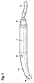
- Fig. 1 shows a diagrammatic representation of a dental Preparation instrument, which is used exclusively for curing one in one Tooth cavity light-curing plastic filling material is used.
- the Preparation instrument contains a handle body 1, on which a banana-shaped curved head part 2 connects.
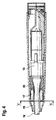
- Fig. 2 which shows the preparation instrument in longitudinal section, it can be seen that the handle body 1 as a holder for two batteries housed therein or Batteries 3 is used. These supply one arranged at the tip 4 of the head part 2 LED 5 with the required voltage. The LED 5 emits light with a Wavelength between 420 and 500 nm. In the head part 2 there is a button or Switch trained, schematically illustrated switching means 6 housed with which the LED can be switched on and off.
- the LED practically forms the light exit surface on the preparation side End of the head part of the preparation instrument.
- the outer closure forms a Window 7, which is not absolutely necessary.
- connection fitting 8 With the corresponding supply line 9, shown in FIG. 1.
- FIG. 3 shows, partly in section, a part of what is known per se Preparation instrument for tooth preparation; at this The preparation instrument is in rotation in a known manner in the head part 10 Movable drive arranged for a drilling instrument (not shown).
- the So-called neck part 11 in which parts of the drive are located, is a LED 12 arranged, the supply lines, not shown, with the necessary voltage of 3 volts and a current of 50 mA is supplied.
- the light emitted by the LED is via an extremely short optical fiber 13 thrown onto the focus 14 representing the preparation site.
- the LED can be used to illuminate the preparation site; it is also conceivable for them at the same time to harden the already mentioned plastic filling materials to use.
- a switchable one is available for the latter application
- white light becomes emitted, which is used for lighting
- Blue light is used as a voltage source to harden the plastic filling materials generated.
- the replacement of the optical waveguide by a mirror is particularly advantageous or a suitable prism, since the light losses are minimal here.
- FIG. 4 shows a so-called ultrasonic scaling hand instrument, which in the middle a drive generally designated 15 and has a tool 16 which can be made to vibrate by the latter.
- a drive generally designated 15 and has a tool 16 which can be made to vibrate by the latter.
- Several LEDs 17 are arranged in a ring around the tool 16. you will be carried by a common bracket 18 through which the corresponding Connection lines are guided.
- the end faces of the LEDs 17 correspond to an annular or annular segment-shaped light guide 19, which Light from the LEDs directs the preparation site. Due to the large number of LEDs sufficient luminance can be achieved.
- LEDs may be advantageous to use or operate the LEDs in such a way that some LEDs blue ", emit light suitable for curing the filling material, the others white ", suitable for illuminating the preparation site. This can be achieved by using either LEDs with different emissions or, as mentioned above, switchable LEDs.
- the measures necessary for switching can either be arranged externally of the preparation instrument or in some cases also in an available free space in the preparation instrument, for example in the grip part of the preparation instrument.
- Control electronics for example, could be arranged in the preparation instrument, which evaluates a modulation signal that is sent by a dental device arranged externally to the preparation instrument via the existing power supply lines.
- the modulation signal sent over the lines can be used between modes Illuminate "and Curing "of the lamps.
- Switching can also be done in the preparation instrument itself with the help of suitable switches and buttons.
- the duty cycle of the LEDs in the case The application for curing the filling materials can be done by a Preselected timer, which is incorporated in said electronics with a corresponding slide or rotary control the curing time pretends.
- FIG. 5 shows in connection with the embodiment according to FIG. 4 a further advantageous variant with which a mechanical switchover from Illuminate " Curing "is possible.
Abstract
Description
Die Erfindung bezieht sich auf ein zahnärztliches Präparationsinstrument mit einer Lichtquelle zum Ausleuchten einer Präparationsstelle und/oder zum Aushärten von in einer Zahnkavität befindlichem lichthärtendem Kunststoff-Füllmaterial.The invention relates to a dental preparation instrument a light source for illuminating a preparation site and / or for Hardening of light-curing plastic filling material located in a tooth cavity.
Präparationsinstrumente, die heute im dentalmedizinischen Bereich eingesetzt werden, sind üblicherweise mit einer Lichtquelle zur Ausleuchtung des Reparationsfeldes ausgestattet. Die dazu verwendeten Lichtquellen emittieren weißes Licht mit einer Farbtemperatur von ca. 2500 K bis 6000 K. In der Regel werden hierzu Halogenlampen eingesetzt, die entweder im Präparationsinstrument selbst oder in einer Anschlußarmatur, an die das Instrument anschließbar ist, angeordnet sind. Die Lichtübertragung von der Lichtquelle zur Austrittsstelle vom Kopfteil des Präparationsinstruments erfolgt über Lichtleiter, die als Glasstab, Glasfaserstab, Faserbündel oder Kunststoffleiter ausgeführt sind. Solche Lichtleiter stellen bei Instrumenten einen nennenswerten Kostenfaktor dar. Gleiches gilt für die Halogenlampen, die üblicherweise auch gekühlt werden müssen. Solche Halogen-Miniaturlampen, wie sie derzeit in der Anwendung sind, haben typischerweise eine Lebensdauer von ca. 40 bis 50 Betriebsstunden.Preparation instruments used today in the dental field are usually with a light source to illuminate the Repair field equipped. Emit the light sources used for this white light with a color temperature of approx. 2500 K to 6000 K. Usually Halogen lamps are used for this purpose, either in the preparation instrument itself or in a connection fitting to which the instrument can be connected, are arranged. The light transmission from the light source to the exit point from The head part of the preparation instrument is made using light guides, which act as glass rods, Glass fiber rod, fiber bundle or plastic conductor are executed. Such Optical fibers represent a significant cost factor for instruments. The same applies to the halogen lamps, which are usually also cooled have to. Such miniature halogen lamps, as they are currently in use, typically have a lifespan of approx. 40 to 50 operating hours.
Neben den vorerwähnten Präparationsinstrumenten, die hauptsächlich als Präparationsinstrumente ausgebildet sind, gibt es auch Präparationsinstrumente, die ausschließlich zum Aushärten von Kunststoff-Füllmaterialien eingesetzt werden. Solche Präparationsinstrumente sind beispielsweise aus der DE-U 77 24 083 bekannt. Die zum Aushärten verwendeten Füllmaterialien sind aus Kunststoff und werden als Ersatzstoff für Amalgam eingesetzt und in die Zahnkavität in plastischem mehr oder weniger viskosem Zustand eingebracht. Nach dem Einbringen werden die Füllmaterialien durch Lichtpolymerisation ausgehärtet. Die Polymerisation erfolgt in der Regel mit blauem Licht, zum Beispiel mit einer Wellenlänge von 420 nm bis 500 nm. Die Lichtquelle ist bei solchen Präparationsinstrumenten entweder im Instrument integriert angeordnet, wobei die Lichtübertragung zum Präparationsfeld durch einen Lichtleiter erfolgt, oder die Lichtquelle ist in der Behandlungseinheit angeordnet, wobei die Übertragung des Lichts von der Behandlungseinheit zum Präparationsinstrument bis zum Lichtaustritt mittels eines Lichtleiters erfolgt. Die Präparationsinstrumente mit integrierter Lichtquelle werden über elektrische Leitungen von der Behandlungseinheit aus versorgt. Auch akkubetriebene Präparationsinstrumente sind an sich bekannt.In addition to the aforementioned preparation instruments, which are mainly used as Preparation instruments are trained, there are also preparation instruments which are used exclusively for curing plastic filling materials become. Such preparation instruments are for example from DE-U 77 24 083 known. The filling materials used for curing are made of Plastic and are used as a substitute for amalgam and in the Dental cavity introduced in a plastic more or less viscous state. After insertion, the filling materials are light polymerized hardened. The polymerization is usually carried out with blue light Example with a wavelength of 420 nm to 500 nm. The light source is at such preparation instruments are either integrated in the instrument, the light is transmitted to the preparation field through an optical fiber, or the light source is arranged in the treatment unit, the Transfer of light from the treatment center to the preparation instrument until the light emerges by means of a light guide. The Preparation instruments with an integrated light source are powered by electrical Lines supplied from the treatment center. Also battery operated Preparation instruments are known per se.
In der DE-C- 196 13 566 wird außerdem eine Vorrichtung zum Aushärten von Füllungsmaterialien aus Kunststoff beschrieben, bei der eine Laserlichtquelle eingesetzt wird.DE-C-196 13 566 also describes a device for curing Filling materials described in plastic, using a laser light source is used.
Der Erfindung liegt die Aufgabe zugrunde, ein zahnärztliches Präparationsinstrument der eingangs genannten Gattung anzugeben, welches die Nachteile der bekannten Präparationsinstrumente nicht aufweist, welches insbesondere kostengünstiger zu erstellen ist, keine zusätzliche Maßnahmen zur Abfuhr der von der Lichtquelle erzeugten Wärme erfordert, und welches in bezug auf die Lichterzeugung und Lichtübertragung weniger Einbauplatz benötigt und damit eine geringere Bauform des Präparationsinstruments zuläßt.The invention has for its object a dental Specification instrument of the type mentioned, which the Disadvantages of the known preparation instruments does not have which In particular, it is cheaper to produce, no additional measures Dissipation of the heat generated by the light source requires, and which in relation less space is required for light generation and light transmission and thus allowing a smaller design of the preparation instrument.
Die gestellte Aufgabe wird durch ein zahnärztliches Präparationsinstrument mit einer Lichtquelle zum Ausleuchten einer Präparationsstelle und/oder zum Aushärten eines in einer Zahnkavität befindlichen lichthärtenden Kunststoff-Füllmaterials gelöst. Erfindungsgemäß ist das Instrument dadurch gekennzeichnet, daß als Lichtquelle eine Kaltlichtquelle eingesetzt ist, welche in unmittelbarer Nähe der Lichtaustrittsstelle des Präparationsinstruments Licht mit der für die jeweilige Anwendung benötigten Wellenlänge bereitstellt.The task is performed using a dental preparation instrument a light source for illuminating a preparation site and / or for Hardening of a light-curing plastic filling material located in a tooth cavity solved. According to the invention, the instrument is thereby characterized in that a cold light source is used as the light source, which in in the immediate vicinity of the light exit point of the light preparation instrument the wavelength required for the respective application.
Als Kaltlichtquelle sollen Leuchtmittel verstanden werden, die im Gegensatz zu Glühlampen bei der hier zur Diskussion stehenden Lichtleistung von ca. 40 Lumen, praktisch keine bzw. nur eine geringe Wärme erzeugen. Besonders vorteilhaft ist die Verwendung einer LED (lichtemittierende Diode) oder einer Miniaturleuchtstofflampe. Die Kaltlichtquelle ist mit Vorteil im Kopfteil des Präparationsinstruments angeordnet, wobei die Lichtverluste besonders gering sind, wenn die Kaltlichtquelle selbst die Lichtaustrittsfläche am präparationsseitigen Ende des Kopfteils des Präparationsinstruments bildet. Die Kaltlichtquelle kann aus mehreren einzelnen Leuchtmitteln gebildet sein. Besonders vorteilhaft ist es, wenn mindestens eines der Leuchtmittel eine zum Aushärten geeignete Wellenlänge emittiert und mindestens ein anderes eine zum Ausleuchten des Präparationsfeldes geeignete Wellenlänge. Ein Präparationsinstrument mit einer solchen Anordnung kann dann sowohl zum Beleuchten als auch zum Aushärten von lichthärtenden Kunststoffüllmaterialien (composites) eingesetzt werden.As a cold light source, illuminants are to be understood which, in contrast to Incandescent lamps with the light output of approx. 40 under discussion here Lumen, practically generate little or no heat. Especially it is advantageous to use an LED (light-emitting diode) or Miniature fluorescent lamp. The cold light source is advantageously in the head part of the Preparation instrument arranged, the light loss is particularly low are when the cold light source itself on the light exit surface preparation-side end of the head part of the preparation instrument. The Cold light source can be formed from several individual lamps. It is particularly advantageous if at least one of the lamps has one for Curing suitable wavelength emitted and at least one other one Illumination of the preparation field suitable wavelength. On Preparation instrument with such an arrangement can then both Illuminate as well as for curing light-curing plastic filling materials (composites) can be used.
Hinsichtlich der geometrischen Anordnung der einzelnen Leuchtmittel ist es denkbar, diese ringförmig, linienförmig oder auch in anderen geometrischen Formationen am Präparationsinstrument anzuordnen. Bei einer Anordnung, die eine alternative Benutzung zum Ausleuchten und zum Aushärten ermöglicht, ist es vorteilhaft, die Leuchtmittel am Umfang der Spitze des Präparationsinstruments verteilt anzuordnen, wobei Lichtquellen gleicher Emissionen jeweils diametral zueinander auf den Fokus der Präparationsstelle ausgerichtet angeordnet sind. Vorteilhafte Ausgestaltungen und Weiterbildungen der Erfindung ergeben sich aus der nachfolgenden Beschreibung mehrerer Ausführungsbeispiele anhand der Zeichnung. Es zeigen:
- Fig. 1
- ein zahnärztliches Präparationsinstrument zum Aushärten von lichthärtenden Kunststoffüllmaterialien in schaubildlicher Darstellung,
- Fig. 2
- das in Fig. 1 gezeigte Präparationsinstrument im Längsschnitt,
- Fig. 3
- einen Teil eines zahnärztlichen Präparationsinstruments, teilweise im Schnitt,
- Fig. 4
- ein Zahnsteinentfernungs-Handinstrument im Schnitt und
- Fig. 5
- eine Variante zu Fig. 4 im Schnitt entlang der Linie V/V in Fig. 4.
- Fig. 1
- a dental preparation instrument for curing light-curing plastic filling materials in a diagrammatic representation,
- Fig. 2
- the preparation instrument shown in Fig. 1 in longitudinal section,
- Fig. 3
- part of a dental preparation instrument, partly in section,
- Fig. 4
- a tartar handheld instrument in section and
- Fig. 5
- 4 along the line V / V in FIG. 4.
Die Fig. 1 zeigt in einer schaubildlichen Darstellung ein zahnärztliches
Präparationsinstrument, welches ausschließlich zum Aushärten eines in einer
Zahnkavität befindlichen lichtaushärtenden Kunststoffüllmaterials dient. Das
Präparationsinstrument enthält einen Griffkörper 1, an den sich ein bananenförmig
gekrümmtes Kopfteil 2 anschließt.Fig. 1 shows a diagrammatic representation of a dental
Preparation instrument, which is used exclusively for curing one in one
Tooth cavity light-curing plastic filling material is used. The
Preparation instrument contains a
Aus Fig. 2, die das Präparationsinstrument im Längsschnitt zeigt, ist ersichtlich,
daß der Griffkörper 1 als Halter für zwei darin untergebrachte Batterien oder
Akkus 3 dient. Diese versorgen eine an der Spitze 4 des Kopfteils 2 angeordnete
LED 5 mit der erforderlichen Spannung. Die LED 5 emittiert Licht mit einer
Wellenlänge zwischen 420 und 500 nm. Im Kopfteil 2 ist ein als Taster oder
Schalter ausgebildetes, schematisch dargestelltes Schaltmittel 6 untergebracht, mit
dem die LED ein- und ausgeschaltet werden kann.From Fig. 2, which shows the preparation instrument in longitudinal section, it can be seen
that the
Die LED bildet hier praktisch die Lichtaustrittsfläche am präparationsseitigen Ende des Kopfteils des Präparationsinstruments. Den äußeren Abschluß bildet ein Fenster 7, das aber nicht zwingend notwendig ist. The LED practically forms the light exit surface on the preparation side End of the head part of the preparation instrument. The outer closure forms a Window 7, which is not absolutely necessary.
Alternativ zu dem dargestellten Präparationsinstrument mit autarker
Energieversorgung ist es denkbar, die Energieversorgung von extern
einzuspeisen; hierzu wäre in bekannter Weise am Ende des Griffkörpers 1 eine
Anschlußarmatur 8 mit entsprechender Versorgungsleitung 9 anzuschließen,
dargestellt in Fig. 1.As an alternative to the shown preparation instrument with self-sufficient
Energy supply is conceivable, the energy supply from external
feed; this would be in a known manner at the end of the
Die Fig. 3 zeigt teilweise im Schnitt einen Teil eines an sich bekannten
Präparationsinstruments zur Präparation von Zähnen; bei diesem
Präparationsinstrument ist in bekannter Weise im Kopfteil 10 ein in Rotation
versetzbarer Antrieb für ein (nicht dargestelltes) Bohrinstrument angeordnet. Im
sogenannten Halsteil 11, in welchem sich Teile des Antriebs befinden, ist eine
LED 12 angeordnet, die über nicht dargestellte Versorgungsleitungen mit der
notwendigen Spannung von 3 Volt und einem Strom von 50 mA versorgt wird.
Das von der LED emittierte Licht wird über einen extrem kurzen Lichtwellenleiter
13 auf den die Präparationsstelle repräsentierenden Fokus 14 geworfen. Die LED
kann hier zum Ausleuchten der Präparationsstelle dienen; denkbar ist es auch, sie
gleichzeitig zum Aushärten der bereits erwähnten Kunststoffüllmaterialien
einzusetzen. Für den zuletzt genannten Anwendungsfall ist eine umschaltbare
LED vorzusehen, die mit zwei verschiedenen Spannungsquellen betrieben werden
kann. Mittels des Anschlusses an die eine Spannungsquelle wird weißes Licht
emittiert, welches zum Beleuchten dient, mittels des Anschlusses an die andere
Spannungsquelle wird blaues Licht zum Aushärten der Kunststoffüllmaterialien
erzeugt.3 shows, partly in section, a part of what is known per se
Preparation instrument for tooth preparation; at this
The preparation instrument is in rotation in a known manner in the
Besonders vorteilhaft ist der Ersatz des Lichtwellenleiters durch einen Spiegel oder ein geeignetes Prisma, da hier die Lichtverluste minimal sind.The replacement of the optical waveguide by a mirror is particularly advantageous or a suitable prism, since the light losses are minimal here.
Die Fig. 4 zeigt ein sogenanntes Ultraschall-Zahnsteinentfernungs-Handinstrument,
welches mittig einen allgemein mit 15 bezeichneten Antrieb und
ein von diesem in Schwingungen versetzbares Werkzeug 16 aufweist. Um das
Werkzeug 16 herum sind mehrere LEDs 17 ringförmig angeordnet. Sie werden
von einer gemeinsamen Halterung 18 getragen, durch die auch die entsprechenden
Anschlußleitungen geführt sind. Die Stirnseiten der LEDs 17 korrespondieren mit
einem kreisring- oder kreisringsegmentartig ausgebildeten Lichtleiter 19, der das
Licht der LEDs auf die Präparationsstelle leitet. Durch die Vielzahl der LEDs
kann eine ausreichende Leuchtdichte erzielt werden.4 shows a so-called ultrasonic scaling hand instrument,
which in the middle a drive generally designated 15 and
has a
Für den Fall, daß mit dem beschriebenen Präparationsinstrument auch ein
Aushärten von Kunststoffüllmaterial durchgeführt werden soll, kann es vorteilhaft
sein, die LEDs so einzusetzen bzw. zu betreiben, daß einige LEDs ![]()
![]()
Die zum Umschalten notwendigen Maßnahmen können entweder extern des
Präparationsinstruments angeordnet sein oder teilweise auch in einem zur
Verfügung stehenden freien Platz im Präparationsinstrument, beispielsweise im
Griffteil des Präparationsinstruments. Im Präparationsinstrument könnte
beispielsweise eine Steuerelektronik angeordnet sein, die ein Modulationssignal
auswertet, das von einem extern des Präparationsinstruments angeordneten
zahnärztlichen Gerät über die vorhandenen Stromzuführungsleitungen gesendet
wird. Das über die Leitungen gesendete Modulationssignal kann dazu verwendet
werden, zwischen dem Modus
Das Umschalten kann auch im Präparationsinstrument selbst mit Hilfe von geeigneten Schaltern und Tastern erfolgen. Die Einschaltdauer der LEDs im Falle der Anwendung zum Aushärten der Füllmaterialien kann durch ein Zeitschaltglied, die in der besagten Elektronik eingearbeitet ist, vorgewählt werden, wobei ein entsprechender Schiebe- oder Drehregler die Aushärtezeit vorgibt. Switching can also be done in the preparation instrument itself with the help of suitable switches and buttons. The duty cycle of the LEDs in the case The application for curing the filling materials can be done by a Preselected timer, which is incorporated in said electronics with a corresponding slide or rotary control the curing time pretends.
Die Fig. 5 zeigt in Verbindung mit der Ausführung nach Fig. 4 eine weitere
vorteilhafte Variante, mit der ein mechanisches Umschalten von
Bei dieser Variante wird davon ausgegangen, daß um das Werkzeug 16 herum 4
LEDs 17 angeordnet sind. Zwischen den LEDs 17 und dem Lichtleiterring ist
zusätzlich zu dem in Fig. 4 beschriebenen Aufbau eine Filterscheibe 20 in der
angegebenen Pfeilrichtung schwenkbar angeordnet. Die den LEDs vorgesetzte
Filterscheibe 20 ist so ausgebildet, daß damit die Lichtfarbe von zumindest 2
LEDs entsprechend verändert werden kann. Die Filterscheibe 20 kann von Hand
betätigt werden; hierzu kann zumindest das eine Ende 21 der Scheibe durch eine
schlitzförmige Öffnung im Gehäuse des Präparationsinstruments hindurchgeführt
sein.In this variant, it is assumed that around the
Claims (13)
Applications Claiming Priority (2)
| Application Number | Priority Date | Filing Date | Title |
|---|---|---|---|
| DE19850834A DE19850834B4 (en) | 1998-11-04 | 1998-11-04 | Dental preparation instrument |
| DE19850834 | 1998-11-04 |
Publications (3)
| Publication Number | Publication Date |
|---|---|
| EP0998880A2 true EP0998880A2 (en) | 2000-05-10 |
| EP0998880A3 EP0998880A3 (en) | 2002-07-31 |
| EP0998880B1 EP0998880B1 (en) | 2005-04-20 |
Family
ID=7886668
Family Applications (1)
| Application Number | Title | Priority Date | Filing Date |
|---|---|---|---|
| EP99120958A Expired - Lifetime EP0998880B1 (en) | 1998-11-04 | 1999-11-03 | Dental preparation instrument |
Country Status (3)
| Country | Link |
|---|---|
| EP (1) | EP0998880B1 (en) |
| AT (1) | ATE293396T1 (en) |
| DE (2) | DE19850834B4 (en) |
Cited By (8)
| Publication number | Priority date | Publication date | Assignee | Title |
|---|---|---|---|---|
| JP2002085351A (en) * | 2000-07-13 | 2002-03-26 | Sunstar Inc | Small-sized illuminator for private part |
| GB2374402A (en) * | 2001-06-29 | 2002-10-16 | Wjw Ltd | A clinical diagnostic instrument with electroluminescent light source |
| EP1260192A2 (en) | 2001-05-23 | 2002-11-27 | Firma Ivoclar Vivadent AG | Illumination device |
| WO2004002361A1 (en) * | 2002-06-28 | 2004-01-08 | 3M Innovative Properties Company | Processes for forming dental materials and device |
| US6692251B1 (en) | 1998-01-20 | 2004-02-17 | Kerr Corporation | Apparatus and method for curing materials with light radiation |
| WO2007045249A1 (en) * | 2005-10-19 | 2007-04-26 | Dentofit A/S | A dental handpiece |
| US9072572B2 (en) | 2009-04-02 | 2015-07-07 | Kerr Corporation | Dental light device |
| US9730778B2 (en) | 2009-04-02 | 2017-08-15 | Kerr Corporation | Curing light device |
Families Citing this family (8)
| Publication number | Priority date | Publication date | Assignee | Title |
|---|---|---|---|---|
| GB2329756A (en) | 1997-09-25 | 1999-03-31 | Univ Bristol | Assemblies of light emitting diodes |
| US6821117B2 (en) | 2001-05-23 | 2004-11-23 | Ivocler Vivadent Ag | Light hardening apparatus for effecting the light hardening of dental restoration pieces |
| DE10125341B4 (en) * | 2001-05-23 | 2006-11-23 | Ivoclar Vivadent Ag | Irradiation device and light curing device |
| US7001057B2 (en) | 2001-05-23 | 2006-02-21 | Ivoclar Vivadent A.G. | Lighting apparatus for guiding light onto a light polymerizable piece to effect hardening thereof |
| DE10144414A1 (en) * | 2001-09-10 | 2003-03-27 | Ivoclar Vivadent Ag | Device for hardening of photo-polymerizable material, especially for dental use, has a target light source that emits a visible light beam that is used to ensure the hardening light beams are correctly focussed |
| EP2298229A1 (en) | 2002-07-25 | 2011-03-23 | Jonathan S. Dahm | Method and apparatus for using light emitting diodes for curing |
| AU2003298561A1 (en) | 2002-08-23 | 2004-05-13 | Jonathan S. Dahm | Method and apparatus for using light emitting diodes |
| DE102006038504B4 (en) * | 2006-08-16 | 2008-09-25 | Sirona Dental Systems Gmbh | Dental treatment light |
Citations (2)
| Publication number | Priority date | Publication date | Assignee | Title |
|---|---|---|---|---|
| DE7724083U1 (en) | 1977-08-02 | 1979-02-01 | Siemens Ag, 1000 Berlin Und 8000 Muenchen | UV RADIATION DEVICE |
| DE19613566A1 (en) | 1996-04-04 | 1997-10-16 | Peter Rechmann | Device and method for curing a light-curing plastic filling material |
Family Cites Families (4)
| Publication number | Priority date | Publication date | Assignee | Title |
|---|---|---|---|---|
| DE2701229A1 (en) * | 1977-01-13 | 1978-07-20 | Kaltenbach & Voigt | Dentist's handpiece emitting UV rays - has air supply hose forming cooling inlet to light source |
| EP0780103A3 (en) * | 1995-12-22 | 1997-12-03 | Heraeus Kulzer GmbH | Irradiation apparatus |
| DE19619154C2 (en) * | 1995-12-22 | 1998-11-12 | Heraeus Kulzer Gmbh | Irradiation device for curing plastics, as well as processes and uses |
| JPH10165419A (en) * | 1996-12-06 | 1998-06-23 | Osada Res Inst Ltd | Light irradiating hand-piece |
-
1998
- 1998-11-04 DE DE19850834A patent/DE19850834B4/en not_active Expired - Fee Related
-
1999
- 1999-11-03 DE DE59911931T patent/DE59911931D1/en not_active Expired - Lifetime
- 1999-11-03 AT AT99120958T patent/ATE293396T1/en active
- 1999-11-03 EP EP99120958A patent/EP0998880B1/en not_active Expired - Lifetime
Patent Citations (2)
| Publication number | Priority date | Publication date | Assignee | Title |
|---|---|---|---|---|
| DE7724083U1 (en) | 1977-08-02 | 1979-02-01 | Siemens Ag, 1000 Berlin Und 8000 Muenchen | UV RADIATION DEVICE |
| DE19613566A1 (en) | 1996-04-04 | 1997-10-16 | Peter Rechmann | Device and method for curing a light-curing plastic filling material |
Cited By (15)
| Publication number | Priority date | Publication date | Assignee | Title |
|---|---|---|---|---|
| US6692251B1 (en) | 1998-01-20 | 2004-02-17 | Kerr Corporation | Apparatus and method for curing materials with light radiation |
| US9622839B2 (en) | 1998-01-20 | 2017-04-18 | Kerr Corporation | Apparatus and method for curing materials with radiation |
| US9572643B2 (en) | 1998-01-20 | 2017-02-21 | Kerr Corporation | Apparatus and method for curing materials with radiation |
| JP2002085351A (en) * | 2000-07-13 | 2002-03-26 | Sunstar Inc | Small-sized illuminator for private part |
| EP1260192A3 (en) * | 2001-05-23 | 2003-05-21 | Firma Ivoclar Vivadent AG | Illumination device |
| EP1260192A2 (en) | 2001-05-23 | 2002-11-27 | Firma Ivoclar Vivadent AG | Illumination device |
| GB2374402B (en) * | 2001-06-29 | 2003-10-15 | Wjw Ltd | A new light source for diagnostic instruments |
| GB2374402A (en) * | 2001-06-29 | 2002-10-16 | Wjw Ltd | A clinical diagnostic instrument with electroluminescent light source |
| WO2004002361A1 (en) * | 2002-06-28 | 2004-01-08 | 3M Innovative Properties Company | Processes for forming dental materials and device |
| US7134875B2 (en) | 2002-06-28 | 2006-11-14 | 3M Innovative Properties Company | Processes for forming dental materials and device |
| WO2007045249A1 (en) * | 2005-10-19 | 2007-04-26 | Dentofit A/S | A dental handpiece |
| US9072572B2 (en) | 2009-04-02 | 2015-07-07 | Kerr Corporation | Dental light device |
| US9693846B2 (en) | 2009-04-02 | 2017-07-04 | Kerr Corporation | Dental light device |
| US9730778B2 (en) | 2009-04-02 | 2017-08-15 | Kerr Corporation | Curing light device |
| US9987110B2 (en) | 2009-04-02 | 2018-06-05 | Kerr Corporation | Dental light device |
Also Published As
| Publication number | Publication date |
|---|---|
| DE59911931D1 (en) | 2005-05-25 |
| EP0998880A3 (en) | 2002-07-31 |
| DE19850834A1 (en) | 2000-05-11 |
| ATE293396T1 (en) | 2005-05-15 |
| DE19850834B4 (en) | 2004-01-29 |
| EP0998880B1 (en) | 2005-04-20 |
Similar Documents
| Publication | Publication Date | Title |
|---|---|---|
| DE19850834B4 (en) | Dental preparation instrument | |
| EP1750571B1 (en) | Laryngoscope | |
| DE69811603T2 (en) | Dental handpiece with built-in light source for diagnostic purposes | |
| DE69816716T2 (en) | Dental handpiece with illuminant | |
| EP2548530B1 (en) | Illuminating device for a medical, in particular dental instrument | |
| DE60019869T2 (en) | Illumination device for a dental or medical instrument | |
| DE3708801C2 (en) | Dental treatment device | |
| DE112009001210T5 (en) | Imaging device used for dental treatment and device for dental treatment equipped with an image pickup device | |
| EP0862899B1 (en) | Dental treatment device | |
| DE102007053336A1 (en) | Signaling device for electrosurgical instruments, adapter for connecting an electrosurgical instrument | |
| DE19619155A1 (en) | Irradiation device for curing plastics | |
| EP0880945A2 (en) | Photopolymerization device | |
| EP0780103A2 (en) | Irradiation apparatus | |
| DE112014003564T5 (en) | Dental treatment instrument with detection function for anomaly sites | |
| CH656062A5 (en) | DENTAL HANDPIECE ARRANGEMENT. | |
| DE10030772B4 (en) | Incident light illumination in microscopes with a ring carrier oriented around the optical axis for receiving illuminants | |
| EP1715804A1 (en) | Manual dental instrument, dental care unit and method for displaying data using a manual dental instrument | |
| DE3328603C2 (en) | ||
| DE10118464A1 (en) | Electrical probe, preferably for eye surgery, has insulator as light conductor optically connected to light generating unit, electrodes with contacts for connecting electrical supply unit | |
| EP0780104A2 (en) | Irradiation apparatus for curing plastic substances | |
| DE3422628A1 (en) | Dental ultrasonic handpiece having an illuminating device | |
| DE102017223191A1 (en) | Dental hand instrument with a vibration exciter and a treatment tool that can be coupled therewith | |
| EP2305163B1 (en) | Lighting device for a dental handpiece | |
| DE3147805A1 (en) | Safety illumination for vehicles | |
| DE3706943A1 (en) | Illuminating device for a hand-held dental instrument |
Legal Events
| Date | Code | Title | Description |
|---|---|---|---|
| PUAI | Public reference made under article 153(3) epc to a published international application that has entered the european phase |
Free format text: ORIGINAL CODE: 0009012 |
|
| AK | Designated contracting states |
Kind code of ref document: A2 Designated state(s): AT BE CH CY DE DK ES FI FR GB GR IE IT LI LU MC NL PT SE |
|
| AX | Request for extension of the european patent |
Free format text: AL;LT;LV;MK;RO;SI |
|
| PUAL | Search report despatched |
Free format text: ORIGINAL CODE: 0009013 |
|
| AK | Designated contracting states |
Kind code of ref document: A3 Designated state(s): AT BE CH CY DE DK ES FI FR GB GR IE IT LI LU MC NL PT SE |
|
| AX | Request for extension of the european patent |
Free format text: AL;LT;LV;MK;RO;SI |
|
| 17P | Request for examination filed |
Effective date: 20030130 |
|
| AKX | Designation fees paid |
Designated state(s): AT BE CH CY DE DK ES FI FR GB GR IE IT LI LU MC NL PT SE |
|
| GRAP | Despatch of communication of intention to grant a patent |
Free format text: ORIGINAL CODE: EPIDOSNIGR1 |
|
| RIC1 | Information provided on ipc code assigned before grant |
Ipc: 7A 61C 19/00 B Ipc: 7A 61C 1/08 A |
|
| RIC1 | Information provided on ipc code assigned before grant |
Ipc: 7A 61C 19/00 B Ipc: 7A 61C 1/08 A |
|
| GRAS | Grant fee paid |
Free format text: ORIGINAL CODE: EPIDOSNIGR3 |
|
| GRAA | (expected) grant |
Free format text: ORIGINAL CODE: 0009210 |
|
| AK | Designated contracting states |
Kind code of ref document: B1 Designated state(s): AT BE CH CY DE DK ES FI FR GB GR IE IT LI LU MC NL PT SE |
|
| PG25 | Lapsed in a contracting state [announced via postgrant information from national office to epo] |
Ref country code: NL Free format text: LAPSE BECAUSE OF FAILURE TO SUBMIT A TRANSLATION OF THE DESCRIPTION OR TO PAY THE FEE WITHIN THE PRESCRIBED TIME-LIMIT Effective date: 20050420 Ref country code: IE Free format text: LAPSE BECAUSE OF FAILURE TO SUBMIT A TRANSLATION OF THE DESCRIPTION OR TO PAY THE FEE WITHIN THE PRESCRIBED TIME-LIMIT Effective date: 20050420 Ref country code: GB Free format text: LAPSE BECAUSE OF FAILURE TO SUBMIT A TRANSLATION OF THE DESCRIPTION OR TO PAY THE FEE WITHIN THE PRESCRIBED TIME-LIMIT Effective date: 20050420 Ref country code: FI Free format text: LAPSE BECAUSE OF FAILURE TO SUBMIT A TRANSLATION OF THE DESCRIPTION OR TO PAY THE FEE WITHIN THE PRESCRIBED TIME-LIMIT Effective date: 20050420 |
|
| REG | Reference to a national code |
Ref country code: GB Ref legal event code: FG4D Free format text: NOT ENGLISH |
|
| REG | Reference to a national code |
Ref country code: CH Ref legal event code: EP |
|
| REG | Reference to a national code |
Ref country code: IE Ref legal event code: FG4D Free format text: LANGUAGE OF EP DOCUMENT: GERMAN |
|
| REF | Corresponds to: |
Ref document number: 59911931 Country of ref document: DE Date of ref document: 20050525 Kind code of ref document: P |
|
| REG | Reference to a national code |
Ref country code: CH Ref legal event code: NV Representative=s name: WILLIAM BLANC & CIE CONSEILS EN PROPRIETE INDUSTRI |
|
| PG25 | Lapsed in a contracting state [announced via postgrant information from national office to epo] |
Ref country code: SE Free format text: LAPSE BECAUSE OF FAILURE TO SUBMIT A TRANSLATION OF THE DESCRIPTION OR TO PAY THE FEE WITHIN THE PRESCRIBED TIME-LIMIT Effective date: 20050720 Ref country code: GR Free format text: LAPSE BECAUSE OF FAILURE TO SUBMIT A TRANSLATION OF THE DESCRIPTION OR TO PAY THE FEE WITHIN THE PRESCRIBED TIME-LIMIT Effective date: 20050720 Ref country code: DK Free format text: LAPSE BECAUSE OF FAILURE TO SUBMIT A TRANSLATION OF THE DESCRIPTION OR TO PAY THE FEE WITHIN THE PRESCRIBED TIME-LIMIT Effective date: 20050720 |
|
| PG25 | Lapsed in a contracting state [announced via postgrant information from national office to epo] |
Ref country code: ES Free format text: LAPSE BECAUSE OF FAILURE TO SUBMIT A TRANSLATION OF THE DESCRIPTION OR TO PAY THE FEE WITHIN THE PRESCRIBED TIME-LIMIT Effective date: 20050731 |
|
| PG25 | Lapsed in a contracting state [announced via postgrant information from national office to epo] |
Ref country code: PT Free format text: LAPSE BECAUSE OF FAILURE TO SUBMIT A TRANSLATION OF THE DESCRIPTION OR TO PAY THE FEE WITHIN THE PRESCRIBED TIME-LIMIT Effective date: 20050920 |
|
| NLV1 | Nl: lapsed or annulled due to failure to fulfill the requirements of art. 29p and 29m of the patents act | ||
| PG25 | Lapsed in a contracting state [announced via postgrant information from national office to epo] |
Ref country code: CY Free format text: LAPSE BECAUSE OF FAILURE TO SUBMIT A TRANSLATION OF THE DESCRIPTION OR TO PAY THE FEE WITHIN THE PRESCRIBED TIME-LIMIT Effective date: 20051103 |
|
| GBV | Gb: ep patent (uk) treated as always having been void in accordance with gb section 77(7)/1977 [no translation filed] |
Effective date: 20050420 |
|
| PG25 | Lapsed in a contracting state [announced via postgrant information from national office to epo] |
Ref country code: MC Free format text: LAPSE BECAUSE OF NON-PAYMENT OF DUE FEES Effective date: 20051130 Ref country code: LU Free format text: LAPSE BECAUSE OF NON-PAYMENT OF DUE FEES Effective date: 20051130 Ref country code: BE Free format text: LAPSE BECAUSE OF NON-PAYMENT OF DUE FEES Effective date: 20051130 |
|
| REG | Reference to a national code |
Ref country code: IE Ref legal event code: FD4D |
|
| PLBE | No opposition filed within time limit |
Free format text: ORIGINAL CODE: 0009261 |
|
| STAA | Information on the status of an ep patent application or granted ep patent |
Free format text: STATUS: NO OPPOSITION FILED WITHIN TIME LIMIT |
|
| ET | Fr: translation filed | ||
| 26N | No opposition filed |
Effective date: 20060123 |
|
| BERE | Be: lapsed |
Owner name: SIRONA DENTAL SYSTEMS G.M.B.H. Effective date: 20051130 |
|
| REG | Reference to a national code |
Ref country code: CH Ref legal event code: PFA Owner name: SIRONA DENTAL SYSTEMS GMBH Free format text: SIRONA DENTAL SYSTEMS GMBH#FABRIKSTRASSE 31#64625 BENSHEIM (DE) -TRANSFER TO- SIRONA DENTAL SYSTEMS GMBH#FABRIKSTRASSE 31#64625 BENSHEIM (DE) |
|
| REG | Reference to a national code |
Ref country code: CH Ref legal event code: PCAR Free format text: NOVAGRAAF SWITZERLAND SA;CHEMIN DE L'ECHO 3;1213 ONEX (CH) |
|
| REG | Reference to a national code |
Ref country code: FR Ref legal event code: PLFP Year of fee payment: 17 |
|
| REG | Reference to a national code |
Ref country code: FR Ref legal event code: PLFP Year of fee payment: 18 |
|
| REG | Reference to a national code |
Ref country code: FR Ref legal event code: PLFP Year of fee payment: 19 |
|
| PGFP | Annual fee paid to national office [announced via postgrant information from national office to epo] |
Ref country code: DE Payment date: 20181203 Year of fee payment: 20 Ref country code: AT Payment date: 20181122 Year of fee payment: 20 |
|
| PGFP | Annual fee paid to national office [announced via postgrant information from national office to epo] |
Ref country code: FR Payment date: 20181123 Year of fee payment: 20 Ref country code: CH Payment date: 20181123 Year of fee payment: 20 Ref country code: IT Payment date: 20181130 Year of fee payment: 20 |
|
| REG | Reference to a national code |
Ref country code: DE Ref legal event code: R071 Ref document number: 59911931 Country of ref document: DE |
|
| REG | Reference to a national code |
Ref country code: CH Ref legal event code: PL |
|
| REG | Reference to a national code |
Ref country code: AT Ref legal event code: MK07 Ref document number: 293396 Country of ref document: AT Kind code of ref document: T Effective date: 20191103 |