EP0996052A2 - Input processing method and input control apparatus - Google Patents
Input processing method and input control apparatus Download PDFInfo
- Publication number
- EP0996052A2 EP0996052A2 EP99302869A EP99302869A EP0996052A2 EP 0996052 A2 EP0996052 A2 EP 0996052A2 EP 99302869 A EP99302869 A EP 99302869A EP 99302869 A EP99302869 A EP 99302869A EP 0996052 A2 EP0996052 A2 EP 0996052A2
- Authority
- EP
- European Patent Office
- Prior art keywords
- state
- touch
- occurrences
- input
- motion
- Prior art date
- Legal status (The legal status is an assumption and is not a legal conclusion. Google has not performed a legal analysis and makes no representation as to the accuracy of the status listed.)
- Ceased
Links
Images


Classifications
-
- G—PHYSICS
- G06—COMPUTING; CALCULATING OR COUNTING
- G06F—ELECTRIC DIGITAL DATA PROCESSING
- G06F3/00—Input arrangements for transferring data to be processed into a form capable of being handled by the computer; Output arrangements for transferring data from processing unit to output unit, e.g. interface arrangements
- G06F3/01—Input arrangements or combined input and output arrangements for interaction between user and computer
- G06F3/048—Interaction techniques based on graphical user interfaces [GUI]
- G06F3/0487—Interaction techniques based on graphical user interfaces [GUI] using specific features provided by the input device, e.g. functions controlled by the rotation of a mouse with dual sensing arrangements, or of the nature of the input device, e.g. tap gestures based on pressure sensed by a digitiser
- G06F3/0488—Interaction techniques based on graphical user interfaces [GUI] using specific features provided by the input device, e.g. functions controlled by the rotation of a mouse with dual sensing arrangements, or of the nature of the input device, e.g. tap gestures based on pressure sensed by a digitiser using a touch-screen or digitiser, e.g. input of commands through traced gestures
- G06F3/04883—Interaction techniques based on graphical user interfaces [GUI] using specific features provided by the input device, e.g. functions controlled by the rotation of a mouse with dual sensing arrangements, or of the nature of the input device, e.g. tap gestures based on pressure sensed by a digitiser using a touch-screen or digitiser, e.g. input of commands through traced gestures for inputting data by handwriting, e.g. gesture or text
Definitions
- the present invention relates to a method for processing input from a touch input device such as a tablet or the like used as an input device, and an input control apparatus for implementing the method.
- Portable information processing apparatuses which are becoming popular, utilize touch input devices such as tablets or digitizers as input devices instead of mice.
- a tablet or digitizer is integrated with a display such as a liquid crystal display by being mounted as a transparent plate over the display or placed underneath the display, and is configured to detect the position of a stylus pen or the like on the display when the stylus pen or the like, as a pointing device, contacts the display screen.
- Such input devices generally called touch screens or touch panels, have been implemented in various ways, including one that uses a resistive film (pressure sensitive tablet) consisting of transparent electrodes bonded to the surface of a display (CRT, LCD, plasma display, etc.) and performs an input operation by touching the screen with a finger or a pen, and one that performs an input operation on the screen with the digitizer, mounted underneath the display, detecting the position of the input by detecting the magnetism being generated at the tip of the pen (when the pen is touched to the screen, magnetism is generated, and the position of the input is detected by the electromagnetic induction type digitizer mounted underneath the display).
- various methods of input position detection have been considered, such as an ultrasonic surface acoustic wave touch panel method that uses ultrasonic waves.
- a tablet like a mouse, is also used to specify a position in a graphical input operation, select a menu or activate a software program by manipulating an icon, and so on.
- a mouse contains mouse buttons, and a mouse operation to press and release a mouse button is called a mouse click, the mouse operation being classified as a single click, double click, etc. according to how many times the button is pressed in succession.
- a mouse click By putting the mouse cursor on a designated icon and clicking the mouse on it, desired processing can be specified.
- a pen operation on a tablet if an operation to touch the pen or the like to the tablet (called a pen down motion) and then lift it off the tablet (called a pen up motion) is called a tap, then moving the mouse cursor and single-clicking or double-clicking the mouse corresponds to performing a single tap or double tap on a designated icon.
- the pen down and pen up motions here embrace operations performed not only by a pen but also by a finger or the like.
- an input processing method for a device which provides input by performing a touch motion on an operating surface comprising: a first step of detecting the length of time of a non-touch state in which no touch motion is performed on the operating surface; and a second step of determining information indicating a touch state in accordance with the detected length of time when a touch motion has occurred.
- an input processing method for a device which provides input by performing a touch motion on an operating surface comprising: a first step of detecting the number of successive occurrences of the touch motion; and a second step of determining information indicating a touch state in accordance with the detected number of occurrences.
- an input processing method for a device which provides input by performing a touch motion on an operating surface comprising: a first step of detecting the number of occurrences of the touch motion over a predetermined length of time; and a second step of determining information indicating a touch state in accordance with the detected number of occurrences.
- an input processing method for a device which provides input by performing a touch motion on an operating surface comprising the steps of: detecting the number of successive occurrences of the touch motion; and determining a corresponding mouse operation in accordance with the detected number of occurrences.
- embodiments of the present invention can provide an input control apparatus for implementing the above method, and a program recording medium which is readable by a computer utilizing the input control apparatus, and on which is recorded a program for implementing the above method.
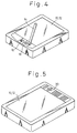
- FIG. 5 is a perspective view of a portable information processing apparatus to which an embodiment of the present invention can be applied.
- a tablet 10 and a liquid crystal display 12 are combined together with one overlaid on top of the other, and function as electronic "paper".
- Various types of tablet 10 are commercially implemented, and embodiments of the present invention are applicable to any type of tablet.
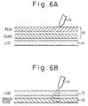
- FIGs 6A and 6B are diagrams for explaining a pressure sensitive tablet and an electromagnetic induction tablet, respectively, as representative examples of tablets.
- the pressure sensitive tablet 10 of Figure 6A consists of a transparent film and glass, and is mounted over the liquid crystal display 12. When the film is brought into contact with the glass by being pressed with a pen or the like, there occurs a change in the resistance value, based on which the position where the contact is made is detected.
- the electromagnetic induction tablet 10 of Figure 6B is constructed from a sensor plate containing a sensor coil, and is placed underneath the liquid crystal display 12. Pen position is determined by detecting the magnetism, generated from the tip of the pen, by means of the sensor coil.
- a hovering icon 22 on the hot pad 20 is an icon used for switching operation between the normal mode and an improved hovering mode according to the present invention.
- the hovering icon 22 is touched during operation in the normal mode, the tablet 10 and display 12 operate in the improved hovering mode according to the present invention until this icon is touched again.
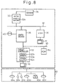
- FIG 8 is a block diagram showing the system configuration of the portable information processing apparatus (the so-called pen computer) shown in Figure 5.
- a multichip module (MCM) 32, south bridge 38, and video graphics array (VGA) controller 36 are connected to a PCI (Peripheral Component Interconnect) bus 30.
- the south bridge 38, tablet controller 52, and ROM (read-only memory) 54 are connected to an ISA (Industry Standard Architecture) bus 50.
- ISA Industry Standard Architecture
- the multichip module 32 contains multiple bare silicon chips mounted on a small printed board, and comprises a CPU, a north bridge, and a secondary cache memory.
- the north bridge is a PCI system controller for controlling data transfers between the CPU, main memory, secondary cache memory, PCI bus, etc.
- a synchronous DRAM (SDRAM) 34 as the main memory is connected to the multichip module 32 via a memory bus.
- SDRAM 34 is characterized by its operation synchronized to the system bus clock.
- the VGA controller 36 controls the liquid crystal display 12 under the VGA standard.
- the south bridge 38 is a bridge, mounted with the PCI bus, that provides connections between the PCI bus and ISA bus on the motherboard, and controls data transfers between the CPU, memory, input/output devices, etc.
- a hard disk drive (HDD) 40 as an auxiliary storage device is connected to the south bridge 38.
- the tablet controller 52 is responsible for controlling the processing of input from the tablet 10 and detecting an operation performed on the hot pad 20, and includes a CPU 52a, a memory (RAM) 52b, and an interface circuit 52c.
- the ROM 54 holds therein an initial program loader.
- a port replicator 60 also called an expansion I/O box, connector box, expansion unit, or the like, is an adaptor which is connected to a notebook computer or a pen computer to enhance their expandability. Usually, it accommodates various connectors, such as a serial port 60d, a parallel port 60a, and a CRT connector 60f, as well as connection ports for a keyboard 60b, a mouse 60c, a floppy disk drive 60e, an Ethernet port, etc. Connectors that are infrequently used when the notebook computer or pen computer is taken on the road are accommodated in the port replicator.
- the floppy disk drive 60e is connected via the port replicator 60, but the floppy disk drive may be connected directly to the pen computer, or alternatively, the pen computer itself may be constructed to contain a floppy disk. Further, the floppy disk drive may be incorporated in a docking station, rather than being connected via the port replicator.
- a docking station is a device that contains a SCSI card, an Ethernet card, a CD-ROM drive, a floppy disk drive, an additional PC card expansion bus, etc., and mostly is shaped so that a notebook computer can fit into it.
- Programs may be provided using the CD-ROM drive or the floppy disk drive accommodated in the docking station.
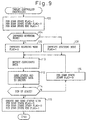
- FIG. 9 is a flowchart illustrating the sequence of processing that the CPU 52a within the tablet controller 52 performs in accordance with the program loaded into the memory 52b of the controller 52.
- This program is usually stored on the HDD 40, and is loaded into the memory of the tablet controller 52 at system power-up.
- the program may also be provided on other recording media such as a floppy disk or a CD-ROM.
- the illustrated process is invoked as an interrupt service routine when a pen down motion is performed on the tablet 10.
- a pen down state flag and a pen down state start flag are both set to 1, and a pen down state end flag is cleared to 0.
- the pen down state flag is a flag that is set to indicate that the current state is the pen down state
- the pen down state start flag is a flag that is set to 1 only once when a transition is made to the pen down state
- the pen down state end flag is a flag that is set to indicate the end of the pen down state.
- an improved hovering mode flag a flag that is set to indicate the improved hovering mode, is cleared to 0, i.e., set OFF.
- the improved hovering mode flag is set to 1, i.e., ON.
- the improved hovering mode flag also is implemented in the memory 52b within the tablet controller 52.
- step 110 which follows step 106 or 108, coordinate data indicating the position at which the tablet 10 is pressed by the pen is detected. In the case of a pressure sensitive tablet, the coordinate data is detected by applying a voltage and measuring the resistance.
- transmission data consisting of status (1 byte) and coordinate data (4 bytes), as shown in Figure 10, is assembled in the memory 52b within the tablet controller 52, and is sent to the pen driver described later.
- the status byte contains a pen down state bit (pen down information), a pen down state start bit, a pen down state end bit, and an improved hovering mode bit, respectively indicating the values of the pen down state flag, pen down state start flag, pen down state end flag, and improved hovering mode flag.
- step 114 it is determined whether the current state is the pen up state, and if the state is not the pen up state, that is, if the state is still the pen down state, the process proceeds to step 116; on the other hand, if the state is the pen up state, the process proceeds to step 118.
- step 116 the pen down state start flag is cleared to 0, and the process loops back to step 110.
- step 118 on the other hand, the pen down state flag and the pen down state start flag are both cleared to 0, while setting the pen down state end flag to 1, and the status reflecting the contents of these flags is created and sent out. In this way, during the period from the pen down to the pen up, data is sent out at predetermined intervals of time (for example, every 5 ms).
- step 114, 116, 110, and 112 is carried out in a loop fashion, as shown in case (B) in Figure 11; during that period, the pen down state flag remains at 1, the pen down state start flag remains at 0, and the pen down state end flag remains at 0.
- the coordinate data is constantly updated in step 110, and the coordinate data and the status are sent out in step 112 at predetermined intervals of time.
- step 118 When a pen up motion is detected to end the pen down state, the process proceeds from step 114 to step 118, and the pen down state flag and pen down state start flag are now at 0 and the pen down state end flag is set to 1, as shown in case (C) in Figure 11. This forms the final status to be sent out.
- the flags make transitions from the states shown in case (A) in Figure 11 directly to the states shown in case (C) in Figure 11 without passing through the states shown in case (B) in Figure 11.
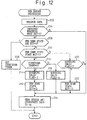
- FIG 12 is a flowchart illustrating a pen driver processing sequence carried out by the CPU 32a within the multichip module 32.
- This pen driver program is usually stored on the HDD 40, and is loaded into the SDRAM 34 at system power-up and executed on the SDRAM 34.
- the program may be provided on other storage media such as a floppy disk or a CD-ROM.
- the illustrated process is initiated upon detecting the arrival of data sent from the tablet controller 52.
- step 202 the data (see Figure 10) sent from the tablet controller 52 is received, and stored in a designated area within the SDRAM 34.
- step 204 the status in the received data is examined to determine whether the improved hovering mode bit is 1 or 0, and if the improved hovering mode bit is 1, the process proceeds to step 206; on the other hand, if the improved hovering mode bit is 0, the process proceeds to step 224.
- step 206 it is determined whether the pen down state end bit contained in the status byte in the received data is 1 or 0, and if the pen down state end bit is 1, the process proceeds to step 208; on the other hand, if the pen down state end bit is 0, the process proceeds to step 210.
- step 208 the countdown timer is set and started, whereupon the routine is terminated. This countdown timer is provided to measure the time interval between a pen up motion and a pen down motion, thereby to determine whether or not the length of time of the pen up state is less than a predetermined threshold value. This timer is implemented as a software timer in the SDRAM 34.
- step 210 it is determined whether the pen down state start bit contained in the status is 1 or 0, and it the pen down state start bit is 1, the process proceeds to step 212; on the other hand, if the pen down state start bit is 0, the process proceeds to step 220.
- step 212 the countdown timer is checked to determine whether the timer has counted down 0 or not, and if the timer has not yet counted down to 0, that is, if the length of time of the pen up state is shorter than the predetermined length of time, the process proceeds to step 214; on the other hand, if the timer has already counted down to 0, that is, if the length of time of the pen up state is longer than the predetermined length of time, the process proceeds to step 218.
- hovering valid flag is set to 1, and the process proceeds to step 216.
- This hovering valid flag is a flag that is set to indicate that the hovering operation is to be performed validly in the improved hovering mode as it is originally intended. The flag is implemented in the SDRAM 34.
- the pen down state bit in the status is changed to 0, and the process proceeds to step 224.
- the hovering valid flag is cleared to 0 to invalidate the hovering operation in the improved hovering mode as an exception and thereby to effect the normal mode; then, the process proceeds to step 224.
- step 220 which is carried out when the pen down state start bit is detected as being 0 in step 210, the hovering valid flag is checked to determine whether it is at 1 or 0, and if the hovering valid flag is at 1, the process proceeds to step 222; on the other hand, if the hovering valid flag is at 0, the process proceeds to step 224.
- step 222 the pen down state bit in the status is changed to 0, and the process proceeds to step 224.
- step 224 the coordinate data and the status containing the pen down state bit after completion of the above processing are sent to the operating system (OS).
- OS operating system
- the pen down state bit (pen down information) in the status reported to the OS along with the coordinate data is as follows.
- steps 202, 204, and 224 are carried out in sequence, so that the pen down state bit remains unchanged at 1 and is reported as is.
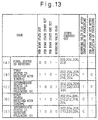
- Pen driver operation in the improved hovering mode will be described below with reference to Figure 13.
- the operation differs depending on the time interval between the pen up motion and the pen down motion detected in the above process, that is, depending on whether or not the length of time of the pen up state is less than the threshold value set by the countdown timer.
- the steps 202, 204, 206, and 208 are carried out, as shown in case (A) in Figure 13, and the countdown timer is thus set and started to count the time until the next pen down motion is detected.
- the first status received indicates that the pen down state bit is 1, the pen down state start bit is 1, and the pen down state end bit is 0, as shown in case (B) in Figure 13, and at this time, the countdown timer is already at 0; accordingly, the steps 202, 204, 206, 210, 212, 214, 216, and 224 are carried out in sequence.
- the hovering valid flag is set to 1 in step 214.
- the pen down state bit is changed to 0 in step 216, and the change state bit is reported to the OS in step 224.
- the number of pen down motions performed within the predetermined time is detected using the countdown timer, and if it is determined in step 212 that the countdown timer reads 0, that means that the number of pen down motions (touch motions) occurring in succession within the predetermined time is 1; as a result, the pen down state bit is not set ON, and it is determined that the state is not the pen down state.
- the pen down state bit is 1, the pen down state start bit is 0, and the pen down end bit is 0, as shown in case (C) in Figure 13 and, at this time, the hovering valid flag is at 1; accordingly, the steps 202, 204, 206, 210, 220, 222, and 224 are carried out in sequence.
- the pen down state bit is changed to 0 in step 222, and the changed state bit is reported to the OS in step 224.
- the next pen down occurs with the countdown timer yet to reach 0, that is, when a pen down motion is detected before the predetermined time has elapsed from the preceding pen up motion
- the first status received indicates that the pen down state bit is 1, the pen down state start bit is 1, and the pen down state end bit is 0, as shown in case (D) in Figure 13, and at this time, the countdown timer has not yet reached 0; accordingly, the steps 202, 204, 206, 210, 212, 218, and 224 are carried out in sequence.
- the hovering valid flag is cleared to 0 in step 218.
- the pen down state bit remains unchanged at 1 and is reported to the OS as it is.
- the number of pen down motions performed within the predetermined time is detected using the countdown timer, and if it is determined in step 212 that the countdown timer has not yet reached 0, that means that the number of pen down motions (touch motions) occurring in succession within the predetermined time is 2 or more; as a result, the pen down state bit is set ON accordingly, and it is determined that the state is the pen down state.
- the pen down state bit In intermediate status received during the pen down state following the states shown in case (D) in Figure 13, the pen down state bit is 1, the pen down state start bit is 0, and the pen down state end bit is 0, as shown in case (E) in Figure 13, and at this time, the hovering valid flag is at 0; accordingly, the steps 202, 204, 206, 210, 220, and 224 are carried out in sequence. As a result, the pen down state bit remains unchanged at 1, and is reported to the OS as it is.
- FIG 14 is a flowchart illustrating the processing sequence of the OS during graphical input processing.
- This OS program is usually stored on the HDD 40, and is loaded into the SDRAM 34 at system power-up and executed on the SDRAM 34 by the CPU 32a within the multichip module 32.
- This OS program may be provided on other storage media such as a floppy disk or a CD-ROM.
- the illustrated process is initiated upon arrival of the data sent from the pen driver. First, in step 302, the data sent from the pen driver is received, and stored in a designated area within the SDRAM 34. Next, in step 304, it is determined whether the pen down state bit in the status is 1 or 0, and if the pen down state bit is 1, the process proceeds to step 306; on the other hand, if the pen down state bit is 0, the process proceeds to step 308.
- step 306 the cursor is moved while maintaining the pen down state which is equivalent to the state in which a mouse is clicked and held down. This causes a dot or line to be drawn, just as if a mouse was dragged.
- step 308 the cursor is merely moved to the position indicated by the received coordinate data.
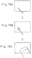
- the immediately following pen tap works just like a pen tap performed in the normal mode. That is, supposing that the state shown in Figure 15A is a state in the improved hovering mode, if a line drawing motion is performed on the tablet after performing a pen tap once, as shown in Figure 15B, a line is drawn on the display as in the normal mode, as shown in Figure 15C. After a series of drawing motions, a pen up state is entered, and after the elapse of a certain amount of time, the hovering operation is again enabled. Using the previously-considered input device, the pen had to be moved outside the screen to switch the mode, as shown in Figures 16A, 16B, 16C, and 16D, but using an embodiment of the present invention, a smooth operation becomes possible.
- Pen motion and operation modes will be described in more detail when a line is drawn by temporarily entering the normal operation mode during the improved hovering mode and then resuming the hovering operation.
- a pen tap is performed to switch the operation, and immediately after that, a line is drawn; when the pen is lifted off the tablet after drawing the line, the hovering operation automatically resumes, as shown in Figure 17.
- the appropriate button had to be pressed to switch to the normal mode, as shown in Figure 18, and then at timing B after drawing the line, another button had to be pressed to switch back to the hovering mode.
- An embodiment of the present invention can eliminate the need for such troublesome button operations.
- an icon manipulation screen such as shown in Figure 19 is used in the improved hovering mode.
- the immediately following pen tap works just like a pen tap performed in the normal mode. More specifically, since the first tap is used for operation switching, the equivalent of a single click of a mouse is accomplished by a double tap of the pen, and the equivalent of a double click of a mouse is accomplished by a triple tap of the pen.
- FIGS 20A and 20B are flowcharts illustrating the processing sequence of the OS during an icon manipulation.
- This OS program is usually stored on the HDD 40, and is loaded into the SDRAM 34 at system power-up and executed on the SDRAM 34 by the CPU 32a within the multichip module 32.
- This OS program may be provided on other storage media such as a floppy disk or a CD-ROM.
- the illustrated process is initiated upon arrival of the data sent from the pen driver. As earlier described, for successively occurring pen taps, the pen driver sets the pen down state bit to 1 for the second and later taps, and sends this bit state to the OS. Accordingly, the OS interprets the second tap as the first mouse click.
- step 402 the data sent from the pen driver is received, and stored in a designated area within the SDRAM 34.
- step 404 it is determined whether the pen down state bit and pen down state start bit in the status are both 1 or not, and if the result is YES, the process proceeds to step 406; on the other hand, if the result is NO, the routine is terminated.
- step 406 it is determined whether an interrupt timer value, which will be set in the following step 408, is 0 or not, and it the timer value is 0, the process proceeds to step 408; on the other hand, if the timer value is not 0, the process proceeds to step 410.
- step 408 the interrupt timer is set, and the routine is terminated.
- step 410 on the other hand, it is decided that the next pen down has occurred within the predetermined time from the previous pen down, and the interrupt timer is reset.
- step 412 it is determined that a double click has occurred.
- an embodiment of the present invention in an information processing apparatus that uses a touch input device such as a tablet or digitizer instead of a mouse as an input device, switching between normal operation and hovering operation can be accomplished with a very simple operation, enhancing its usability.
- a touch input device such as a tablet or digitizer instead of a mouse
- switching between normal operation and hovering operation can be accomplished with a very simple operation, enhancing its usability.
- an embodiment of the present invention is also applicable to an apparatus that is operated by a finger.
Abstract
Description
- The present invention relates to a method for processing input from a touch input device such as a tablet or the like used as an input device, and an input control apparatus for implementing the method.
- Portable information processing apparatuses, which are becoming popular, utilize touch input devices such as tablets or digitizers as input devices instead of mice. Generally, a tablet or digitizer is integrated with a display such as a liquid crystal display by being mounted as a transparent plate over the display or placed underneath the display, and is configured to detect the position of a stylus pen or the like on the display when the stylus pen or the like, as a pointing device, contacts the display screen.
- Such input devices, generally called touch screens or touch panels, have been implemented in various ways, including one that uses a resistive film (pressure sensitive tablet) consisting of transparent electrodes bonded to the surface of a display (CRT, LCD, plasma display, etc.) and performs an input operation by touching the screen with a finger or a pen, and one that performs an input operation on the screen with the digitizer, mounted underneath the display, detecting the position of the input by detecting the magnetism being generated at the tip of the pen (when the pen is touched to the screen, magnetism is generated, and the position of the input is detected by the electromagnetic induction type digitizer mounted underneath the display). In addition to such pressure sensitive tablet and electromagnetic induction digitizer methods, various methods of input position detection have been considered, such as an ultrasonic surface acoustic wave touch panel method that uses ultrasonic waves.
- A tablet, like a mouse, is also used to specify a position in a graphical input operation, select a menu or activate a software program by manipulating an icon, and so on.
- A mouse contains mouse buttons, and a mouse operation to press and release a mouse button is called a mouse click, the mouse operation being classified as a single click, double click, etc. according to how many times the button is pressed in succession. By putting the mouse cursor on a designated icon and clicking the mouse on it, desired processing can be specified. In the case of a pen operation on a tablet, if an operation to touch the pen or the like to the tablet (called a pen down motion) and then lift it off the tablet (called a pen up motion) is called a tap, then moving the mouse cursor and single-clicking or double-clicking the mouse corresponds to performing a single tap or double tap on a designated icon. The pen down and pen up motions here embrace operations performed not only by a pen but also by a finger or the like.
- In a graphical input operation, when a
tablet 10 is touched with apen 14, as shown in Figure 1 of the accompanying drawings, a dot is drawn on adisplay 12 at the position of the touch. The figure shows thetablet 10 and display 12 as a single integral unit. When thepen 14 is moved whilst holding it touched to thetablet 10, as shown in Figure 2 of the accompanying drawings, a line corresponding in its movement is drawn on thedisplay 12. - In the case of a mouse, there is a mouse operation, called drag, in which the mouse is moved while keeping the mouse button pressed down; in a graphical input operation, a line is drawn when the mouse is dragged. On the other hand, when the mouse is moved without holding down a mouse button, the mouse cursor merely moves on the display.
- In the case of a graphical input operation by a pen on a tablet, on the other hand, if a dot or line were always drawn with a pen down motion, an operation to move the cursor without drawing a dot or line, such as the operation shown in Figure 3 of the accompanying drawings, could not be accomplished. To avoid this, an operation mode is provided in which even when the pen is actually touched to the tablet, the motion is not interpreted as a pen down motion but the mouse cursor is merely caused to move. This mode is called a hovering mode. To switch the operation between normal mode and hovering mode, a normal
mode selection button 16 and a hoveringmode selection button 18 are provided outside the display screen, as shown in Figure 4 of the accompanying drawings. In an icon manipulation in the hovering mode, a pen tap on an icon only results in positioning the cursor on that icon. - In this way, an input operation on a touch input device such as a tablet or digitizer has required mode switching using the buttons provided outside the screen, and in the case of an input operation that requires frequent mode switching, the operation has been very tiring and inefficient for an operator.
- It is desirable to provide an input processing method and input control apparatus for a touch input device that enables operation mode switching to be accomplished with a very simple operation.
- According to an embodiment of a first aspect of the present invention, there is provided an input processing method for a device which provides input by performing a touch motion on an operating surface, comprising: a first step of detecting the length of time of a non-touch state in which no touch motion is performed on the operating surface; and a second step of determining information indicating a touch state in accordance with the detected length of time when a touch motion has occurred.
- According to an embodiment of a second aspect of the present invention, there is provided an input processing method for a device which provides input by performing a touch motion on an operating surface, comprising: a first step of detecting the number of successive occurrences of the touch motion; and a second step of determining information indicating a touch state in accordance with the detected number of occurrences.
- According to an embodiment of a third aspect of the present invention, there is provided an input processing method for a device which provides input by performing a touch motion on an operating surface, comprising: a first step of detecting the number of occurrences of the touch motion over a predetermined length of time; and a second step of determining information indicating a touch state in accordance with the detected number of occurrences.
- According to an embodiment of a fourth aspect of the present invention, there is provided an input processing method for a device which provides input by performing a touch motion on an operating surface, comprising the steps of: detecting the number of successive occurrences of the touch motion; and determining a corresponding mouse operation in accordance with the detected number of occurrences.
- Furthermore, embodiments of the present invention, can provide an input control apparatus for implementing the above method, and a program recording medium which is readable by a computer utilizing the input control apparatus, and on which is recorded a program for implementing the above method.
- Reference will now be made, by way of example, to the accompanying drawings, in which:
- Figure 1, discussed hereinbefore, is a diagram for explaining the motion for drawing a dot with a pen;
- Figure 2, discussed hereinbefore, is a diagram for explaining the motion for drawing a line with a pen;
- Figure 3, discussed hereinbefore, is a diagram for explaining the motion for merely moving cursor coordinates without drawing a line;
- Figure 4, discussed hereinbefore, is a diagram for explaining mode switching buttons according to a previously-considered input device;
- Figure 5 is a perspective view of a portable information processing apparatus to which an embodiment of the present invention can be applied;
- Figures 6A and 6B are diagrams for use in explaining a pressure sensitive tablet and an electromagnetic induction tablet, respectively, as representative examples of tablets;
- Figure 7 is a diagram showing the details of a hot pad;
- Figure 8 is a block diagram showing the system configuration of the portable information processing apparatus shown in Figure 5;
- Figure 9 is a flowchart illustrating the sequence of processing performed by an exemplary tablet controller;
- Figure 10 is a diagram showing the possible format of data sent out from a tablet controller;
- Figure 11 is a diagram for use in explaining the possible operation of a tablet controller;
- Figure 12 is a flowchart illustrating a pen driver processing sequence;
- Figure 13 is a diagram for use in explaining the possible operation of a pen driver;
- Figure 14 is a flowchart illustrating a processing sequence of an OS during graphical input processing;
- Figures 15A, 15B, and 15C are diagrams for use in explaining a method of operation mode switching for use in an embodiment of the present invention;
- Figures 16A, 16B, 16C, and 16D are diagrams for use in explaining a method of operation mode switching used in a previously-considered input device;
- Figure 17 is a diagram for explaining pen motion and operation modes according to an embodiment of the present invention;
- Figure 18 is a diagram for explaining pen motion and operation modes according to a previously-considered input device;
- Figure 19 is a diagram showing an example of an icon manipulation screen; and
- Figures 20A and 20B are flowcharts illustrating a processing sequence of an OS during an icon manipulation.
-
- An embodiment of the present invention will be described below with reference to the accompanying drawings. The embodiment hereinafter described deals with an example that uses a pen (or stylus), but the invention is also applicable to devices that are operated using fingers. For example, ultrasonic surface acoustic wave touch panels and pressure sensitive tablets permit position input by touching them with a finger without using a pen. Embodiments of the present invention do not exclude application to such devices.
- Figure 5 is a perspective view of a portable information processing apparatus to which an embodiment of the present invention can be applied. A
tablet 10 and aliquid crystal display 12 are combined together with one overlaid on top of the other, and function as electronic "paper". Various types oftablet 10 are commercially implemented, and embodiments of the present invention are applicable to any type of tablet. - Figures 6A and 6B are diagrams for explaining a pressure sensitive tablet and an electromagnetic induction tablet, respectively, as representative examples of tablets. The pressure
sensitive tablet 10 of Figure 6A consists of a transparent film and glass, and is mounted over theliquid crystal display 12. When the film is brought into contact with the glass by being pressed with a pen or the like, there occurs a change in the resistance value, based on which the position where the contact is made is detected. Theelectromagnetic induction tablet 10 of Figure 6B is constructed from a sensor plate containing a sensor coil, and is placed underneath theliquid crystal display 12. Pen position is determined by detecting the magnetism, generated from the tip of the pen, by means of the sensor coil. - The details of a
hot pad 20 in Figure 5 are illustrated in Figure 7. Ahovering icon 22 on thehot pad 20 is an icon used for switching operation between the normal mode and an improved hovering mode according to the present invention. When thehovering icon 22 is touched during operation in the normal mode, thetablet 10 anddisplay 12 operate in the improved hovering mode according to the present invention until this icon is touched again. - Figure 8 is a block diagram showing the system configuration of the portable information processing apparatus (the so-called pen computer) shown in Figure 5. A multichip module (MCM) 32,
south bridge 38, and video graphics array (VGA)controller 36 are connected to a PCI (Peripheral Component Interconnect)bus 30. Thesouth bridge 38,tablet controller 52, and ROM (read-only memory) 54 are connected to an ISA (Industry Standard Architecture)bus 50. - The
multichip module 32 contains multiple bare silicon chips mounted on a small printed board, and comprises a CPU, a north bridge, and a secondary cache memory. The north bridge is a PCI system controller for controlling data transfers between the CPU, main memory, secondary cache memory, PCI bus, etc. A synchronous DRAM (SDRAM) 34 as the main memory is connected to themultichip module 32 via a memory bus. TheSDRAM 34 is characterized by its operation synchronized to the system bus clock. - The
VGA controller 36 controls theliquid crystal display 12 under the VGA standard. Thesouth bridge 38 is a bridge, mounted with the PCI bus, that provides connections between the PCI bus and ISA bus on the motherboard, and controls data transfers between the CPU, memory, input/output devices, etc. A hard disk drive (HDD) 40 as an auxiliary storage device is connected to thesouth bridge 38. - The
tablet controller 52 is responsible for controlling the processing of input from thetablet 10 and detecting an operation performed on thehot pad 20, and includes aCPU 52a, a memory (RAM) 52b, and aninterface circuit 52c. The ROM 54 holds therein an initial program loader. - A
port replicator 60, also called an expansion I/O box, connector box, expansion unit, or the like, is an adaptor which is connected to a notebook computer or a pen computer to enhance their expandability. Usually, it accommodates various connectors, such as aserial port 60d, aparallel port 60a, and aCRT connector 60f, as well as connection ports for akeyboard 60b, amouse 60c, afloppy disk drive 60e, an Ethernet port, etc. Connectors that are infrequently used when the notebook computer or pen computer is taken on the road are accommodated in the port replicator. - In the present embodiment, the
floppy disk drive 60e is connected via theport replicator 60, but the floppy disk drive may be connected directly to the pen computer, or alternatively, the pen computer itself may be constructed to contain a floppy disk. Further, the floppy disk drive may be incorporated in a docking station, rather than being connected via the port replicator. A docking station is a device that contains a SCSI card, an Ethernet card, a CD-ROM drive, a floppy disk drive, an additional PC card expansion bus, etc., and mostly is shaped so that a notebook computer can fit into it. - Programs may be provided using the CD-ROM drive or the floppy disk drive accommodated in the docking station.
- Figure 9 is a flowchart illustrating the sequence of processing that the
CPU 52a within thetablet controller 52 performs in accordance with the program loaded into thememory 52b of thecontroller 52. This program is usually stored on theHDD 40, and is loaded into the memory of thetablet controller 52 at system power-up. The program may also be provided on other recording media such as a floppy disk or a CD-ROM. The illustrated process is invoked as an interrupt service routine when a pen down motion is performed on thetablet 10. - First, in
step 102, upon detecting the pen down motion, a pen down state flag and a pen down state start flag are both set to 1, and a pen down state end flag is cleared to 0. The pen down state flag is a flag that is set to indicate that the current state is the pen down state, and the pen down state start flag is a flag that is set to 1 only once when a transition is made to the pen down state, while the pen down state end flag is a flag that is set to indicate the end of the pen down state. These flags are implemented in thememory 52b within thetablet controller 52. Next, instep 104, it is determined whether the current operation mode is the improved hovering mode or not, based on the operation performed on the hoveringicon 22 on thehot pad 20. If the current mode is not the improved hovering mode, that is, if the current mode is the normal mode, the process proceeds to step 106; on the other hand, if the current mode is the improved hovering mode, the process proceeds to step 108. - In
step 106, an improved hovering mode flag, a flag that is set to indicate the improved hovering mode, is cleared to 0, i.e., set OFF. On the other hand, instep 108, the improved hovering mode flag is set to 1, i.e., ON. The improved hovering mode flag also is implemented in thememory 52b within thetablet controller 52. Instep 110, which followsstep tablet 10 is pressed by the pen is detected. In the case of a pressure sensitive tablet, the coordinate data is detected by applying a voltage and measuring the resistance. - Next, in
step 112, transmission data consisting of status (1 byte) and coordinate data (4 bytes), as shown in Figure 10, is assembled in thememory 52b within thetablet controller 52, and is sent to the pen driver described later. The status byte contains a pen down state bit (pen down information), a pen down state start bit, a pen down state end bit, and an improved hovering mode bit, respectively indicating the values of the pen down state flag, pen down state start flag, pen down state end flag, and improved hovering mode flag. - In
step 114, it is determined whether the current state is the pen up state, and if the state is not the pen up state, that is, if the state is still the pen down state, the process proceeds to step 116; on the other hand, if the state is the pen up state, the process proceeds to step 118. Instep 116, the pen down state start flag is cleared to 0, and the process loops back tostep 110. Instep 118, on the other hand, the pen down state flag and the pen down state start flag are both cleared to 0, while setting the pen down state end flag to 1, and the status reflecting the contents of these flags is created and sent out. In this way, during the period from the pen down to the pen up, data is sent out at predetermined intervals of time (for example, every 5 ms). - The state transitions of the flags in the improved hovering mode in the above-described process will be described with reference to Figure 11. First, when the pen down motion is detected, the pen down state flag is set to 1, the pen down state start flag is set to 1, the pen down state end flag is cleared to 0, and the improved hovering mode flag is set to 1 in
steps step 112 together with the coordinate data detected instep 110. - As long as the pen down state continues, the process consisting of
steps step 110, and the coordinate data and the status are sent out instep 112 at predetermined intervals of time. - When a pen up motion is detected to end the pen down state, the process proceeds from
step 114 to step 118, and the pen down state flag and pen down state start flag are now at 0 and the pen down state end flag is set to 1, as shown in case (C) in Figure 11. This forms the final status to be sent out. In the above process, if a pen up motion is detected immediately following the pen down motion, the flags make transitions from the states shown in case (A) in Figure 11 directly to the states shown in case (C) in Figure 11 without passing through the states shown in case (B) in Figure 11. - Figure 12 is a flowchart illustrating a pen driver processing sequence carried out by the
CPU 32a within themultichip module 32. This pen driver program is usually stored on theHDD 40, and is loaded into theSDRAM 34 at system power-up and executed on theSDRAM 34. The program may be provided on other storage media such as a floppy disk or a CD-ROM. The illustrated process is initiated upon detecting the arrival of data sent from thetablet controller 52. First, instep 202, the data (see Figure 10) sent from thetablet controller 52 is received, and stored in a designated area within theSDRAM 34. Next, instep 204, the status in the received data is examined to determine whether the improved hovering mode bit is 1 or 0, and if the improved hovering mode bit is 1, the process proceeds to step 206; on the other hand, if the improved hovering mode bit is 0, the process proceeds to step 224. - In
step 206, it is determined whether the pen down state end bit contained in the status byte in the received data is 1 or 0, and if the pen down state end bit is 1, the process proceeds to step 208; on the other hand, if the pen down state end bit is 0, the process proceeds to step 210. Instep 208, the countdown timer is set and started, whereupon the routine is terminated. This countdown timer is provided to measure the time interval between a pen up motion and a pen down motion, thereby to determine whether or not the length of time of the pen up state is less than a predetermined threshold value. This timer is implemented as a software timer in theSDRAM 34. - In
step 210, it is determined whether the pen down state start bit contained in the status is 1 or 0, and it the pen down state start bit is 1, the process proceeds to step 212; on the other hand, if the pen down state start bit is 0, the process proceeds to step 220. Instep 212, the countdown timer is checked to determine whether the timer has counted down 0 or not, and if the timer has not yet counted down to 0, that is, if the length of time of the pen up state is shorter than the predetermined length of time, the process proceeds to step 214; on the other hand, if the timer has already counted down to 0, that is, if the length of time of the pen up state is longer than the predetermined length of time, the process proceeds to step 218. - In
step 214, hovering valid flag is set to 1, and the process proceeds to step 216. This hovering valid flag is a flag that is set to indicate that the hovering operation is to be performed validly in the improved hovering mode as it is originally intended. The flag is implemented in theSDRAM 34. Instep 216, the pen down state bit in the status is changed to 0, and the process proceeds to step 224. On the other hand, instep 218, the hovering valid flag is cleared to 0 to invalidate the hovering operation in the improved hovering mode as an exception and thereby to effect the normal mode; then, the process proceeds to step 224. - In
step 220, which is carried out when the pen down state start bit is detected as being 0 instep 210, the hovering valid flag is checked to determine whether it is at 1 or 0, and if the hovering valid flag is at 1, the process proceeds to step 222; on the other hand, if the hovering valid flag is at 0, the process proceeds to step 224. Instep 222, the pen down state bit in the status is changed to 0, and the process proceeds to step 224. In thefinal step 224, the coordinate data and the status containing the pen down state bit after completion of the above processing are sent to the operating system (OS). - As the result of the above pen driver processing, the pen down state bit (pen down information) in the status reported to the OS along with the coordinate data is as follows. When the mode is not the improved hovering mode, that is, when the mode is the normal mode, steps 202, 204, and 224 are carried out in sequence, so that the pen down state bit remains unchanged at 1 and is reported as is.
- Pen driver operation in the improved hovering mode, on the other hand, will be described below with reference to Figure 13. In the improved hovering mode, the operation differs depending on the time interval between the pen up motion and the pen down motion detected in the above process, that is, depending on whether or not the length of time of the pen up state is less than the threshold value set by the countdown timer.
- First, since the pen down state end bit is 1 in the final status, that is, the status received when the pen down state has ended by detecting a pen up motion, the
steps - Then, when the next pen down occurs with the countdown timer already reaching 0, that is, when a pen down motion is detected after the predetermined time has elapsed from the preceding pen up motion, the first status received indicates that the pen down state bit is 1, the pen down state start bit is 1, and the pen down state end bit is 0, as shown in case (B) in Figure 13, and at this time, the countdown timer is already at 0; accordingly, the
steps step 214. The pen down state bit is changed to 0 instep 216, and the change state bit is reported to the OS instep 224. In other words, the number of pen down motions performed within the predetermined time is detected using the countdown timer, and if it is determined instep 212 that the countdown timer reads 0, that means that the number of pen down motions (touch motions) occurring in succession within the predetermined time is 1; as a result, the pen down state bit is not set ON, and it is determined that the state is not the pen down state. - In intermediate status received during the pen down state following the states shown in case (B) in Figure 13, the pen down state bit is 1, the pen down state start bit is 0, and the pen down end bit is 0, as shown in case (C) in Figure 13 and, at this time, the hovering valid flag is at 1; accordingly, the
steps step 222, and the changed state bit is reported to the OS instep 224. - On the other hand, when the next pen down occurs with the countdown timer yet to reach 0, that is, when a pen down motion is detected before the predetermined time has elapsed from the preceding pen up motion, the first status received indicates that the pen down state bit is 1, the pen down state start bit is 1, and the pen down state end bit is 0, as shown in case (D) in Figure 13, and at this time, the countdown timer has not yet reached 0; accordingly, the
steps step 218. The pen down state bit remains unchanged at 1 and is reported to the OS as it is. In other words, the number of pen down motions performed within the predetermined time is detected using the countdown timer, and if it is determined instep 212 that the countdown timer has not yet reached 0, that means that the number of pen down motions (touch motions) occurring in succession within the predetermined time is 2 or more; as a result, the pen down state bit is set ON accordingly, and it is determined that the state is the pen down state. - In intermediate status received during the pen down state following the states shown in case (D) in Figure 13, the pen down state bit is 1, the pen down state start bit is 0, and the pen down state end bit is 0, as shown in case (E) in Figure 13, and at this time, the hovering valid flag is at 0; accordingly, the
steps - Following the states shown in case (B), (C), (D), or (E) in Figure 13, when the pen down states ends by detecting a pen up motion, and the final status is received, the countdown timer is started, as previously described, to prepare for the next pen down, as shown in case (A) in Figure 13.
- Figure 14 is a flowchart illustrating the processing sequence of the OS during graphical input processing. This OS program is usually stored on the
HDD 40, and is loaded into theSDRAM 34 at system power-up and executed on theSDRAM 34 by theCPU 32a within themultichip module 32. This OS program may be provided on other storage media such as a floppy disk or a CD-ROM. The illustrated process is initiated upon arrival of the data sent from the pen driver. First, instep 302, the data sent from the pen driver is received, and stored in a designated area within theSDRAM 34. Next, instep 304, it is determined whether the pen down state bit in the status is 1 or 0, and if the pen down state bit is 1, the process proceeds to step 306; on the other hand, if the pen down state bit is 0, the process proceeds to step 308. - In
step 306, the cursor is moved while maintaining the pen down state which is equivalent to the state in which a mouse is clicked and held down. This causes a dot or line to be drawn, just as if a mouse was dragged. On the other hand, instep 308, the cursor is merely moved to the position indicated by the received coordinate data. - According to the above-described tablet controller, pen driver, and OS processing operations, by just performing an extra pen tap in the improved hovering mode, the immediately following pen tap works just like a pen tap performed in the normal mode. That is, supposing that the state shown in Figure 15A is a state in the improved hovering mode, if a line drawing motion is performed on the tablet after performing a pen tap once, as shown in Figure 15B, a line is drawn on the display as in the normal mode, as shown in Figure 15C. After a series of drawing motions, a pen up state is entered, and after the elapse of a certain amount of time, the hovering operation is again enabled. Using the previously-considered input device, the pen had to be moved outside the screen to switch the mode, as shown in Figures 16A, 16B, 16C, and 16D, but using an embodiment of the present invention, a smooth operation becomes possible.
- Pen motion and operation modes will be described in more detail when a line is drawn by temporarily entering the normal operation mode during the improved hovering mode and then resuming the hovering operation. In an embodiment of the present invention, immediately before drawing a line, a pen tap is performed to switch the operation, and immediately after that, a line is drawn; when the pen is lifted off the tablet after drawing the line, the hovering operation automatically resumes, as shown in Figure 17. In the previously-considered method, on the other hand, at timing A before drawing a line, the appropriate button had to be pressed to switch to the normal mode, as shown in Figure 18, and then at timing B after drawing the line, another button had to be pressed to switch back to the hovering mode. An embodiment of the present invention can eliminate the need for such troublesome button operations.
- Next, a description will be given of icon manipulations in the improved hovering mode according to an embodiment of the present invention. Suppose an icon manipulation screen such as shown in Figure 19 is used in the improved hovering mode. In this case also, by just performing an extra pen tap, the immediately following pen tap works just like a pen tap performed in the normal mode. More specifically, since the first tap is used for operation switching, the equivalent of a single click of a mouse is accomplished by a double tap of the pen, and the equivalent of a double click of a mouse is accomplished by a triple tap of the pen.
- Figures 20A and 20B are flowcharts illustrating the processing sequence of the OS during an icon manipulation. This OS program is usually stored on the
HDD 40, and is loaded into theSDRAM 34 at system power-up and executed on theSDRAM 34 by theCPU 32a within themultichip module 32. This OS program may be provided on other storage media such as a floppy disk or a CD-ROM. The illustrated process is initiated upon arrival of the data sent from the pen driver. As earlier described, for successively occurring pen taps, the pen driver sets the pen down state bit to 1 for the second and later taps, and sends this bit state to the OS. Accordingly, the OS interprets the second tap as the first mouse click. - First, in
step 402, the data sent from the pen driver is received, and stored in a designated area within theSDRAM 34. Next, instep 404, it is determined whether the pen down state bit and pen down state start bit in the status are both 1 or not, and if the result is YES, the process proceeds to step 406; on the other hand, if the result is NO, the routine is terminated. - In
step 406, it is determined whether an interrupt timer value, which will be set in the followingstep 408, is 0 or not, and it the timer value is 0, the process proceeds to step 408; on the other hand, if the timer value is not 0, the process proceeds to step 410. Instep 408, the interrupt timer is set, and the routine is terminated. Instep 410, on the other hand, it is decided that the next pen down has occurred within the predetermined time from the previous pen down, and the interrupt timer is reset. In thenext step 412, it is determined that a double click has occurred. - When an interrupt is caused by the interrupt timer set in
step 408, the process shown in Figure 20B is carried out. Since this process is invoked when the next pen down did not occur within the predetermined time from the previous pen down, it is determined instep 450 that a single click has occurred. - When a single click is detected, a file selection or other operation is performed, and when a double click is detected, a program in the file is activated, for example.
- As described above, according to an embodiment of the present invention, in an information processing apparatus that uses a touch input device such as a tablet or digitizer instead of a mouse as an input device, switching between normal operation and hovering operation can be accomplished with a very simple operation, enhancing its usability. Though the embodiment has been described by dealing with an example that uses a pen (or stylus), an embodiment of the present invention is also applicable to an apparatus that is operated by a finger.
- The invention may be embodied in other specific forms without departing from the spirit or essential characteristics thereof. The present embodiment is therefore to be considered in all respects as illustrative and not restrictive, the scope of the invention being indicated by the appended claims rather than by the foregoing description and all changes which come within the meaning and range of equivalency of the claims are therefore intended to be embraced therein.
- It will be appreciated that computer programs can be stored on a variety of media, such as floppy disks, hard disks, CD-ROMs, etc., or downloaded into a computer, for example from the Internet. It is intended that the attached claims should encompass computer programs in all these, and similar, forms.
Claims (55)
- An input processing method for a device which provides input by performing a touch motion on an operating surface, comprising:a first step of detecting the length of time of a non-touch state in which no touch motion is performed on said operating surface; anda second step of determining information indicating a touch state in accordance with said detected length of time when a touch motion has occurred.
- An input processing method as claimed in claim 1, wherein when a touch state occurs, said first step detects the length of time of said non-touch state that follows said touch state.
- An input processing method as claimed in claim 1, wherein said second step determines that the state is the touch state if said detected length of time is less than a predetermined length of time.
- An input processing method for a device which provides input by performing a touch motion on an operating surface, comprising:a first step of detecting the number of successive occurrences of said touch motion; anda second step of determining information indicating a touch state in accordance with said detected number of occurrences.
- An input processing method as claimed in claim 4, wherein said first step detects the number of occurrences of said touch motion over a predetermined length of time.
- An input processing method for a device which provides input by performing a touch motion on an operating surface, comprising:a first step of detecting the number of occurrences of said touch motion over a predetermined length of time; anda second step of determining information indicating a touch state in accordance with said detected number of occurrences.
- An input processing method as claimed in any one of claims 4 to 6, wherein when said number of occurrences is 1, said second step determines that the state is not the touch state occurring in relation to said touch motion, and when said detected number of occurrences is 2 or more, then determines that the state is the touch state.
- An input processing method as claimed in any one of claims 4 to 6, wherein when said detected number of occurrences is 2, it is determined that a single click has occurred, and/or when said detected number of occurrences is 3, it is determined that a double click has occurred.
- An input processing method as claimed in any one of claims 1 to 7, whereinsaid device is a device that displays a cursor in a display section,said cursor has a first state for directing the processing of a manipulation target displayed in said display section, and a second state for not directing the processing of said manipulation target, andthere is included a step in which said cursor changes from said second state to said first state in response to said touch state indicating information.
- An input processing method as claimed in any one of claims 1 to 9, including the step of determining information indicating the termination of said touch state after said second step has determined said touch state indicating information and said touch state has ended.
- An input processing method as claimed in any one of claims 1 to 7, whereinsaid device is a device that displays a cursor in a display section,said cursor has a first state for directing the processing of a manipulation target displayed in said display section, and a second state for not directing the processing of said manipulation target, andthere is included a step in which said cursor changes from said first state to said second state when said touch motion has ended.
- An input processing method as claimed in any one of claims 1 to 11, including the step of performing information processing in response to said touch state indicating information.
- An input processing method as claimed in any one of claims 1 to 4, wherein said touch motion is performed using a pen on said operating surface, andsaid non-touch state is a pen up state, and/or said touch state is a pen down state.
- An input processing method as claimed in claim 9, wherein said first state is a cursor-clicked state, and/or said second state is a hovering state.
- An input processing method for a device which provides input by performing a touch motion on an operating surface, comprising the steps of:detecting the number of successive occurrences of said touch motion; anddetermining a corresponding mouse operation in accordance with said detected number of occurrences.
- An input processing method as claimed in claim 15, wherein said corresponding mouse operation determining step determines that a single click has occurred when said detected number of occurrences is 2, and/or determines that a double click has occurred when said detected number of occurrences is 3.
- An input processing method as claimed in any one of claims 1 to 16, wherein said device comprises a display section and said touch motion operating surface is arranged in said display section.
- An input processing method as claimed in any one of claims 1 to 16, wherein each of said steps is carried out only when a designated mode is set active.
- An input control apparatus for a touch input device which provides input by performing a touch motion on an operating surface, comprising:a first unit detecting the length of time of a non-touch state in which no touch motion is performed on said operating surface; anda second unit determining information indicating a touch state in accordance with said detected length of time when a touch motion has occurred.
- An input control apparatus as claimed in claim 19, wherein when a touch state occurs, said first step detects the length of time of said non-touch state that follows said touch state.
- An input control apparatus as claimed in claim 19, wherein said second unit determines that the state is the touch state if said detected length of time is less than a predetermined length of time
- An input control apparatus for a device which provides input by performing a touch motion on an operating surface, comprising:a first unit detecting the number of successive occurrences of said touch motion; anda second unit determining information indicating a touch state in accordance with said detected number of occurrences.
- An input control apparatus as claimed in claim 22, wherein said first unit detects the number of occurrences of said touch motion over a predetermined length of time.
- An input control apparatus for a device which provides input by performing a touch motion on an operating surface, comprising:a first unit detecting the number of occurrences of said touch motion over a predetermined length of time; anda second unit determining information indicating a touch state in accordance with said detected number of occurrences.
- An input control apparatus as claimed in any one of claims 22 to 24, wherein when said number of occurrences is 1, said second unit determines that the state is not the touch state occurring in relation to said touch motion, and when said detected number of occurrences is 2 or more, then determines that the state is the touch state.
- An input control apparatus as claimed in any one of claims 22 to 25, wherein when said detected number of occurrences is 2, it is determined that a single click has occurred, and/or when said detected number of occurrences is 3, it is determined that a double click has occurred.
- An input control apparatus as claimed in any one of claims 19 to 25, whereinsaid device is a device that displays a cursor in a display section,said cursor has a first state for directing the processing of a manipulation target displayed in said display section, and a second state for not directing the processing of said manipulation target, andthere is included a unit for changing said cursor from said second state to said first state in response to said touch state indicating information.
- An input control apparatus as claimed in any one of claims 19 to 27, including a unit determining information indicating the termination of said touch state after said second unit has determined said touch state indicating information and said touch state has ended.
- An input control apparatus as claimed in any one of claims 19 to 25, whereinsaid device is a device that displays a cursor in a display section,said cursor has a first state for directing the processing of a manipulation target displayed in said display section, and a second state for not directing the processing of said manipulation target, andthere is included a unit changing said cursor from said first state to said second state when said touch motion has ended.
- An input control apparatus as claimed in any one of claims 19 to 29, including a unit performing information processing in response to said touch state indicating information.
- An input control apparatus as claimed in any one of claims 19 to 22, wherein said touch motion is performed using a pen on said operating surface, andsaid non-touch state is a pen up state, and/or said touch state is a pen down state.
- An input control apparatus as claimed in claim 27, wherein said first state is a cursor-clicked state, and/or said second state is a hovering state.
- An input control apparatus for a device which provides input by performing a touch motion on an operating surface, comprising:a unit detecting the number of successive occurrences of said touch motion; anda unit determining a corresponding mouse operation in accordance with said detected number of occurrences.
- An input control apparatus as claimed in claim 33, wherein said corresponding mouse operation determining unit determines that a single click has occurred when said detected number of occurrences is 2, and/or determines that a double click has occurred when said detected number of occurrences is 3.
- An input control apparatus as claimed in any one of claims 19 to 33, wherein each of said units operates only when a designated mode is set active.
- An information processing apparatus comprising: said touch input device; and an input control apparatus as claimed in any one of claims 19 to 34.
- An information processing apparatus comprising: said touch input device; a display device; and an input control apparatus as claimed in any one of claims 19 to 34, and wherein: the operating surface of said touch input device is arranged in said display device.
- A recording medium readable by a computer, said computer using a device which provides input by performing a touch motion on an operating surface, said recording medium having a program recorded thereon for causing said computer to implement:a first function detecting the length of time of a non-touch state in which no touch motion is performed on said operating surface; anda second function determining information indicating a touch state in accordance with said detected length of time when a touch motion has occurred.
- A recording medium as claimed in claim 38, wherein when a touch state occurs, said first function detects the length of time of said non-touch state that follows said touch state.
- A recording medium as claimed in claim 38, wherein said second function determines that the state is the touch state if said detected length of time is less than a predetermined length of time.
- A recording medium readable by a computer, said computer using a device which provides input by performing a touch motion on an operating surface, said recording medium having a program recorded thereon for causing said computer to implement:a first function detecting the number of successive occurrences of said touch motion; anda second function for determining information indicating a touch state in accordance with said detected number of occurrences.
- A recording medium as claimed in claim 41, wherein said first function detects the number of occurrences of said touch motion over a predetermined length of time.
- A recording medium readable by a computer, said computer using a device which provides input by performing a touch motion on an operating surface, said recording medium having a program recorded thereon for causing said computer to implement:a first function detecting the number of occurrences of said touch motion over a predetermined length of time; anda second function determining information indicating a touch state in accordance with said detected number of occurrences.
- A recording medium as claimed in any one of claims 41 to 43, wherein when said number of occurrences is 1, said second function determines that the state is not the touch state occurring in relation to said touch motion, and when said detected number of occurrences is 2 or more, then determines that the state is the touch state.
- A recording medium as claimed in any one of claims 41 to 44, including a function for causing said computer to determine that a single click has occurred when said detected number of occurrences is 2, and/or a function for causing said computer to determine that a double click has occurred when said detected number of occurrences is 3.
- A recording medium as claimed in any one of claims 38 to 44, whereinsaid device is a device that displays a cursor in a display section, said cursor having a first state for directing the processing of a manipulation target displayed in said display section, and a second state for not directing the processing of said manipulation target, andthere is included a function changing said cursor from said second state to said first state in response to said touch state indicating information.
- A recording medium as claimed in any one of claims 38 to 46, including a function for determining information indicating the termination of said touch state after said second function has determined said touch state indicating information and said touch state has ended.
- A recording medium as claimed in any one of claims 38 to 44, whereinsaid device is a device that displays a cursor in a display section,said cursor has a first state for directing the processing of a manipulation target displayed in said display section, and a second state for not directing the processing of said manipulation target, andthere is included a function for changing said cursor from said first state to said second state when said touch motion has ended.
- A recording medium as claimed in any one of claims 38 to 48, including a function for performing information processing in response to said touch state indicating information.
- A recording medium as claimed in any one of claims 38 to 41, wherein said touch motion is performed using a pen on said operating surface, andsaid non-touch state is a pen up state, and/or said touch state is a pen down state.
- A recording medium as claimed in claim 46, wherein said first state is a cursor-clicked state, and/or said second state is a hovering state.
- A recording medium readable by a computer, said computer using a device which provides input by performing a touch motion on an operating surface, said recording medium having a program recorded thereon for causing said computer to implement:a function detecting the number of successive occurrences of said touch motion; anda function determining a corresponding mouse operation in accordance with said detected number of occurrences.
- A recording medium as claimed in claim 52, wherein said corresponding mouse operation determining function determines that a single click has occurred when said detected number of occurrences is 2, and/or determines that a double click has occurred when said detected number of occurrences is 3.
- A recording medium as claimed in any one of claims 38 to 53, wherein said device comprises a display section and said touch motion operating surface is arranged in said display section.
- A computer program which, when running on a computer, is operable to carry out the steps of a method as claimed in any one of claims 1 to 18.
Applications Claiming Priority (2)
| Application Number | Priority Date | Filing Date | Title |
|---|---|---|---|
| JP29704698A JP2000122808A (en) | 1998-10-19 | 1998-10-19 | Input processing method and input control unit |
| JP29704698 | 1998-10-19 |
Publications (2)
| Publication Number | Publication Date |
|---|---|
| EP0996052A2 true EP0996052A2 (en) | 2000-04-26 |
| EP0996052A3 EP0996052A3 (en) | 2006-03-15 |
Family
ID=17841523
Family Applications (1)
| Application Number | Title | Priority Date | Filing Date |
|---|---|---|---|
| EP99302869A Ceased EP0996052A3 (en) | 1998-10-19 | 1999-04-13 | Input processing method and input control apparatus |
Country Status (4)
| Country | Link |
|---|---|
| US (1) | US6930672B1 (en) |
| EP (1) | EP0996052A3 (en) |
| JP (1) | JP2000122808A (en) |
| CN (5) | CN100381986C (en) |
Cited By (2)
| Publication number | Priority date | Publication date | Assignee | Title |
|---|---|---|---|---|
| US6904570B2 (en) | 2001-06-07 | 2005-06-07 | Synaptics, Inc. | Method and apparatus for controlling a display of data on a display screen |
| CN102707885A (en) * | 2012-05-02 | 2012-10-03 | 华为终端有限公司 | Operation method of touch screen and terminal |
Families Citing this family (59)
| Publication number | Priority date | Publication date | Assignee | Title |
|---|---|---|---|---|
| US6897853B2 (en) * | 2000-11-10 | 2005-05-24 | Microsoft Corp. | Highlevel active pen matrix |
| JP4653297B2 (en) * | 2000-11-27 | 2011-03-16 | 富士通株式会社 | Control device, electronic device, and medium |
| JP4430842B2 (en) * | 2001-10-01 | 2010-03-10 | 株式会社リコー | Input processing method, display device with coordinate input function, and program |
| EP1805579A1 (en) * | 2004-09-14 | 2007-07-11 | Nokia Corporation | A method for using a pointing device |
| US20060077182A1 (en) * | 2004-10-08 | 2006-04-13 | Studt Peter C | Methods and systems for providing user selectable touch screen functionality |
| CN100383713C (en) * | 2004-12-31 | 2008-04-23 | 联想(北京)有限公司 | Information input device of portable electronic device and control method thereof |
| WO2008007372A2 (en) | 2006-07-12 | 2008-01-17 | N-Trig Ltd. | Hover and touch detection for a digitizer |
| US8686964B2 (en) * | 2006-07-13 | 2014-04-01 | N-Trig Ltd. | User specific recognition of intended user interaction with a digitizer |
| US8063886B2 (en) * | 2006-07-18 | 2011-11-22 | Iee International Electronics & Engineering S.A. | Data input device |
| KR100948050B1 (en) * | 2006-11-23 | 2010-03-19 | 주식회사 메디슨 | Portable ultrasound system |
| US20080169132A1 (en) * | 2007-01-03 | 2008-07-17 | Yao Ding | Multiple styli annotation system |
| KR100891100B1 (en) * | 2007-07-27 | 2009-03-31 | 삼성전자주식회사 | Trajectory estimation apparatus and method based on pen-type optical mouse |
| US8487884B2 (en) * | 2008-06-24 | 2013-07-16 | Freescale Semiconductor, Inc. | Touch screen detection and diagnostics |
| JP5107205B2 (en) * | 2008-10-22 | 2012-12-26 | レノボ・シンガポール・プライベート・リミテッド | Display connection adapter and display connection system |
| US20100107116A1 (en) * | 2008-10-27 | 2010-04-29 | Nokia Corporation | Input on touch user interfaces |
| US20100107067A1 (en) * | 2008-10-27 | 2010-04-29 | Nokia Corporation | Input on touch based user interfaces |
| US8433138B2 (en) * | 2008-10-29 | 2013-04-30 | Nokia Corporation | Interaction using touch and non-touch gestures |
| JP2010218422A (en) * | 2009-03-18 | 2010-09-30 | Toshiba Corp | Information processing apparatus and method for controlling the same |
| JP5442479B2 (en) * | 2010-02-05 | 2014-03-12 | 株式会社ワコム | Indicator, position detection device and position detection method |
| US9098138B2 (en) * | 2010-08-27 | 2015-08-04 | Apple Inc. | Concurrent signal detection for touch and hover sensing |
| JP2011054213A (en) * | 2010-12-14 | 2011-03-17 | Toshiba Corp | Information processor and control method |
| US8928336B2 (en) | 2011-06-09 | 2015-01-06 | Ford Global Technologies, Llc | Proximity switch having sensitivity control and method therefor |
| US8975903B2 (en) | 2011-06-09 | 2015-03-10 | Ford Global Technologies, Llc | Proximity switch having learned sensitivity and method therefor |
| JP5325943B2 (en) * | 2011-07-12 | 2013-10-23 | 富士フイルム株式会社 | Information processing apparatus, information processing method, and program |
| US10004286B2 (en) | 2011-08-08 | 2018-06-26 | Ford Global Technologies, Llc | Glove having conductive ink and method of interacting with proximity sensor |
| US9143126B2 (en) | 2011-09-22 | 2015-09-22 | Ford Global Technologies, Llc | Proximity switch having lockout control for controlling movable panel |
| US10112556B2 (en) | 2011-11-03 | 2018-10-30 | Ford Global Technologies, Llc | Proximity switch having wrong touch adaptive learning and method |
| US8994228B2 (en) | 2011-11-03 | 2015-03-31 | Ford Global Technologies, Llc | Proximity switch having wrong touch feedback |
| US8878438B2 (en) | 2011-11-04 | 2014-11-04 | Ford Global Technologies, Llc | Lamp and proximity switch assembly and method |
| US20130201107A1 (en) * | 2012-02-08 | 2013-08-08 | Microsoft Corporation | Simulating Input Types |
| US8796566B2 (en) | 2012-02-28 | 2014-08-05 | Grayhill, Inc. | Rotary pushbutton and touchpad device and system and method for detecting rotary movement, axial displacement and touchpad gestures |
| US9520875B2 (en) | 2012-04-11 | 2016-12-13 | Ford Global Technologies, Llc | Pliable proximity switch assembly and activation method |
| US9531379B2 (en) | 2012-04-11 | 2016-12-27 | Ford Global Technologies, Llc | Proximity switch assembly having groove between adjacent proximity sensors |
| US9197206B2 (en) | 2012-04-11 | 2015-11-24 | Ford Global Technologies, Llc | Proximity switch having differential contact surface |
| US9831870B2 (en) | 2012-04-11 | 2017-11-28 | Ford Global Technologies, Llc | Proximity switch assembly and method of tuning same |
| US8933708B2 (en) | 2012-04-11 | 2015-01-13 | Ford Global Technologies, Llc | Proximity switch assembly and activation method with exploration mode |
| US9184745B2 (en) | 2012-04-11 | 2015-11-10 | Ford Global Technologies, Llc | Proximity switch assembly and method of sensing user input based on signal rate of change |
| US9065447B2 (en) | 2012-04-11 | 2015-06-23 | Ford Global Technologies, Llc | Proximity switch assembly and method having adaptive time delay |
| US9568527B2 (en) | 2012-04-11 | 2017-02-14 | Ford Global Technologies, Llc | Proximity switch assembly and activation method having virtual button mode |
| US9287864B2 (en) | 2012-04-11 | 2016-03-15 | Ford Global Technologies, Llc | Proximity switch assembly and calibration method therefor |
| US9559688B2 (en) | 2012-04-11 | 2017-01-31 | Ford Global Technologies, Llc | Proximity switch assembly having pliable surface and depression |
| US9219472B2 (en) | 2012-04-11 | 2015-12-22 | Ford Global Technologies, Llc | Proximity switch assembly and activation method using rate monitoring |
| US9660644B2 (en) | 2012-04-11 | 2017-05-23 | Ford Global Technologies, Llc | Proximity switch assembly and activation method |
| US9944237B2 (en) | 2012-04-11 | 2018-04-17 | Ford Global Technologies, Llc | Proximity switch assembly with signal drift rejection and method |
| US9136840B2 (en) | 2012-05-17 | 2015-09-15 | Ford Global Technologies, Llc | Proximity switch assembly having dynamic tuned threshold |
| US8981602B2 (en) | 2012-05-29 | 2015-03-17 | Ford Global Technologies, Llc | Proximity switch assembly having non-switch contact and method |
| US9337832B2 (en) | 2012-06-06 | 2016-05-10 | Ford Global Technologies, Llc | Proximity switch and method of adjusting sensitivity therefor |
| US9641172B2 (en) | 2012-06-27 | 2017-05-02 | Ford Global Technologies, Llc | Proximity switch assembly having varying size electrode fingers |
| KR102084041B1 (en) | 2012-08-24 | 2020-03-04 | 삼성전자 주식회사 | Operation Method And System for function of Stylus pen |
| US8922340B2 (en) | 2012-09-11 | 2014-12-30 | Ford Global Technologies, Llc | Proximity switch based door latch release |
| US8796575B2 (en) | 2012-10-31 | 2014-08-05 | Ford Global Technologies, Llc | Proximity switch assembly having ground layer |
| US9311204B2 (en) | 2013-03-13 | 2016-04-12 | Ford Global Technologies, Llc | Proximity interface development system having replicator and method |
| US9673925B2 (en) * | 2013-03-15 | 2017-06-06 | Universal Electronics Inc. | System and method for monitoring user interactions with a universal controlling device |
| US9395824B2 (en) * | 2013-10-18 | 2016-07-19 | Synaptics Incorporated | Active pen with improved interference performance |
| US10038443B2 (en) | 2014-10-20 | 2018-07-31 | Ford Global Technologies, Llc | Directional proximity switch assembly |
| US9654103B2 (en) | 2015-03-18 | 2017-05-16 | Ford Global Technologies, Llc | Proximity switch assembly having haptic feedback and method |
| US9548733B2 (en) | 2015-05-20 | 2017-01-17 | Ford Global Technologies, Llc | Proximity sensor assembly having interleaved electrode configuration |
| CN105354086B (en) * | 2015-11-25 | 2019-07-16 | 广州视睿电子科技有限公司 | A kind of method and terminal automatically switching write mode |
| CN114356124B (en) * | 2021-12-06 | 2023-09-29 | 深圳市千分一智能技术有限公司 | Cycle self-adaption method, device, active pen and computer readable storage medium |
Citations (2)
| Publication number | Priority date | Publication date | Assignee | Title |
|---|---|---|---|---|
| WO1997036225A1 (en) * | 1996-03-28 | 1997-10-02 | Synaptics, Inc. | Object position detector with edge motion feature and gesture recognition |
| US5757368A (en) * | 1995-03-27 | 1998-05-26 | Cirque Corporation | System and method for extending the drag function of a computer pointing device |
Family Cites Families (19)
| Publication number | Priority date | Publication date | Assignee | Title |
|---|---|---|---|---|
| US4040010A (en) * | 1975-11-06 | 1977-08-02 | Stanford Research Institute | Identification by handwriting verification |
| JPS62224820A (en) | 1986-03-26 | 1987-10-02 | Hitachi Ltd | Switching device for coordinate input mode |
| JP2538878B2 (en) * | 1986-05-26 | 1996-10-02 | 株式会社東芝 | Information input device and method for controlling character entry area in information input device |
| DE69031137T2 (en) * | 1989-02-15 | 1998-01-29 | Canon Kk | Coordinate input device |
| US5166415A (en) * | 1990-03-30 | 1992-11-24 | Union Carbide Chemicals & Plastics Technology Corporation | Selective production of diethylenetriamine and aminoethylethanolamine |
| JP3094338B2 (en) * | 1990-06-14 | 2000-10-03 | ソニー株式会社 | Information processing apparatus and information processing method |
| DE69209576D1 (en) * | 1991-05-10 | 1996-05-09 | Takeda Chemical Industries Ltd | Pyridine derivatives, their production and use |
| JPH04360230A (en) | 1991-06-07 | 1992-12-14 | Matsushita Electric Ind Co Ltd | Menu control device and its control method |
| JP3256994B2 (en) | 1991-10-30 | 2002-02-18 | 富士通株式会社 | Display target movement method by touch input |
| US6097392A (en) * | 1992-09-10 | 2000-08-01 | Microsoft Corporation | Method and system of altering an attribute of a graphic object in a pen environment |
| JPH06161650A (en) | 1992-11-27 | 1994-06-10 | Toshiba Corp | Information controller with pressure sensitive tablet input device |
| JPH0785032A (en) | 1993-06-30 | 1995-03-31 | Toshiba Corp | Device and method for preparing document |
| US5572651A (en) * | 1993-10-15 | 1996-11-05 | Xerox Corporation | Table-based user interface for retrieving and manipulating indices between data structures |
| JPH08286807A (en) * | 1995-04-18 | 1996-11-01 | Canon Inc | Data processing unit and method for recognizing gesture |
| JP2713227B2 (en) * | 1995-05-15 | 1998-02-16 | 日本電気株式会社 | Input terminal device |
| JPH0981320A (en) * | 1995-09-20 | 1997-03-28 | Matsushita Electric Ind Co Ltd | Pen input type selection input device and method therefor |
| JPH1097504A (en) * | 1996-09-25 | 1998-04-14 | Sharp Corp | Information processor |
| US6057830A (en) * | 1997-01-17 | 2000-05-02 | Tritech Microelectronics International Ltd. | Touchpad mouse controller |
| US6333994B1 (en) * | 1999-03-31 | 2001-12-25 | International Business Machines Corporation | Spatial sorting and formatting for handwriting recognition |
-
1998
- 1998-10-19 JP JP29704698A patent/JP2000122808A/en active Pending
-
1999
- 1999-04-13 EP EP99302869A patent/EP0996052A3/en not_active Ceased
- 1999-04-13 US US09/290,419 patent/US6930672B1/en not_active Expired - Fee Related
- 1999-05-06 CN CNB991063422A patent/CN100381986C/en not_active Expired - Fee Related
- 1999-05-06 CN CNB2005100791579A patent/CN1322405C/en not_active Expired - Fee Related
- 1999-05-06 CN CNB2005100791600A patent/CN1322407C/en not_active Expired - Fee Related
- 1999-05-06 CN CNB2005100791583A patent/CN100336000C/en not_active Expired - Fee Related
- 1999-05-06 CN CNB2005100791598A patent/CN1322406C/en not_active Expired - Fee Related
Patent Citations (2)
| Publication number | Priority date | Publication date | Assignee | Title |
|---|---|---|---|---|
| US5757368A (en) * | 1995-03-27 | 1998-05-26 | Cirque Corporation | System and method for extending the drag function of a computer pointing device |
| WO1997036225A1 (en) * | 1996-03-28 | 1997-10-02 | Synaptics, Inc. | Object position detector with edge motion feature and gesture recognition |
Cited By (4)
| Publication number | Priority date | Publication date | Assignee | Title |
|---|---|---|---|---|
| US6904570B2 (en) | 2001-06-07 | 2005-06-07 | Synaptics, Inc. | Method and apparatus for controlling a display of data on a display screen |
| USRE47676E1 (en) | 2001-06-07 | 2019-10-29 | Wacom Co., Ltd. | Method and apparatus for controlling a display of data on a display screen |
| CN102707885A (en) * | 2012-05-02 | 2012-10-03 | 华为终端有限公司 | Operation method of touch screen and terminal |
| CN102707885B (en) * | 2012-05-02 | 2016-04-13 | 华为终端有限公司 | A kind of method of operating of touch-screen and terminal |
Also Published As
| Publication number | Publication date |
|---|---|
| JP2000122808A (en) | 2000-04-28 |
| CN1696884A (en) | 2005-11-16 |
| EP0996052A3 (en) | 2006-03-15 |
| CN1322405C (en) | 2007-06-20 |
| CN1251439A (en) | 2000-04-26 |
| CN100381986C (en) | 2008-04-16 |
| CN1696885A (en) | 2005-11-16 |
| CN1696881A (en) | 2005-11-16 |
| CN1322406C (en) | 2007-06-20 |
| CN1696883A (en) | 2005-11-16 |
| CN100336000C (en) | 2007-09-05 |
| US6930672B1 (en) | 2005-08-16 |
| CN1322407C (en) | 2007-06-20 |
Similar Documents
| Publication | Publication Date | Title |
|---|---|---|
| US6930672B1 (en) | Input processing method and input control apparatus | |
| US6657615B2 (en) | Input processing method and input processing device for implementing same | |
| US7088344B2 (en) | Data processor, I/O device, touch panel controlling method, recording medium, and program transmitter | |
| US20090140999A1 (en) | Information-processing apparatus and programs used therein | |
| US20020067346A1 (en) | Graphical user interface for devices having small tactile displays | |
| EP2551759A2 (en) | Gesture recognition method and touch system incorporating the same | |
| JP2001051798A (en) | Method for dividing touch screen at data input | |
| JP2012208962A (en) | Arrangement of virtual input device onto touch screen type user interface | |
| US20040100451A1 (en) | Electronic apparatus and operation mode switching method | |
| JP4171509B2 (en) | Input processing method and input processing apparatus for implementing the same | |
| US7495658B2 (en) | Control device, electronic apparatus and medium for outputting information in accordance with an operation relative to an input device | |
| US20040104895A1 (en) | Information processing unit, control method for information processing unit for performing operation according to user input operation, and computer program | |
| US8327294B2 (en) | Method and system to reduce workload and skills required in usage of mouse or other pointing devices | |
| JP4904239B2 (en) | Input processing method and input control apparatus | |
| JP3350339B2 (en) | Drag mode setting method | |
| JP4904240B2 (en) | Input processing method and input control apparatus | |
| US10540086B2 (en) | Apparatus, method and computer program product for information processing and input determination | |
| CN114217727B (en) | Electronic device and touch method thereof | |
| JP2001195187A (en) | Information processor | |
| JP2001216089A (en) | Touch panel type computer and input device used for the touch panel type computer |
Legal Events
| Date | Code | Title | Description |
|---|---|---|---|
| PUAI | Public reference made under article 153(3) epc to a published international application that has entered the european phase |
Free format text: ORIGINAL CODE: 0009012 |
|
| AK | Designated contracting states |
Kind code of ref document: A2 Designated state(s): AT BE CH CY DE DK ES FI FR GB GR IE IT LI LU MC NL PT SE |
|
| AX | Request for extension of the european patent |
Free format text: AL;LT;LV;MK;RO;SI |
|
| PUAL | Search report despatched |
Free format text: ORIGINAL CODE: 0009013 |
|
| AK | Designated contracting states |
Kind code of ref document: A3 Designated state(s): AT BE CH CY DE DK ES FI FR GB GR IE IT LI LU MC NL PT SE |
|
| AX | Request for extension of the european patent |
Extension state: AL LT LV MK RO SI |
|
| 17P | Request for examination filed |
Effective date: 20060911 |
|
| AKX | Designation fees paid |
Designated state(s): DE FR GB |
|
| 17Q | First examination report despatched |
Effective date: 20070312 |
|
| STAA | Information on the status of an ep patent application or granted ep patent |
Free format text: STATUS: THE APPLICATION HAS BEEN REFUSED |
|
| 18R | Application refused |
Effective date: 20160521 |