EP0995555A1 - Robot arm - Google Patents
Robot arm Download PDFInfo
- Publication number
- EP0995555A1 EP0995555A1 EP98119468A EP98119468A EP0995555A1 EP 0995555 A1 EP0995555 A1 EP 0995555A1 EP 98119468 A EP98119468 A EP 98119468A EP 98119468 A EP98119468 A EP 98119468A EP 0995555 A1 EP0995555 A1 EP 0995555A1
- Authority
- EP
- European Patent Office
- Prior art keywords
- gripper
- gear
- robot arm
- arm according
- rod
- Prior art date
- Legal status (The legal status is an assumption and is not a legal conclusion. Google has not performed a legal analysis and makes no representation as to the accuracy of the status listed.)
- Withdrawn
Links
Images


Classifications
-
- B—PERFORMING OPERATIONS; TRANSPORTING
- B25—HAND TOOLS; PORTABLE POWER-DRIVEN TOOLS; MANIPULATORS
- B25J—MANIPULATORS; CHAMBERS PROVIDED WITH MANIPULATION DEVICES
- B25J15/00—Gripping heads and other end effectors
- B25J15/02—Gripping heads and other end effectors servo-actuated
- B25J15/0253—Gripping heads and other end effectors servo-actuated comprising parallel grippers
-
- B—PERFORMING OPERATIONS; TRANSPORTING
- B25—HAND TOOLS; PORTABLE POWER-DRIVEN TOOLS; MANIPULATORS
- B25J—MANIPULATORS; CHAMBERS PROVIDED WITH MANIPULATION DEVICES
- B25J9/00—Programme-controlled manipulators
- B25J9/02—Programme-controlled manipulators characterised by movement of the arms, e.g. cartesian coordinate type
- B25J9/023—Cartesian coordinate type
- B25J9/026—Gantry-type
-
- B—PERFORMING OPERATIONS; TRANSPORTING
- B25—HAND TOOLS; PORTABLE POWER-DRIVEN TOOLS; MANIPULATORS
- B25J—MANIPULATORS; CHAMBERS PROVIDED WITH MANIPULATION DEVICES
- B25J9/00—Programme-controlled manipulators
- B25J9/10—Programme-controlled manipulators characterised by positioning means for manipulator elements
- B25J9/102—Gears specially adapted therefor, e.g. reduction gears
Definitions
- the invention relates to a robot arm according to the preamble of claim 1.
- Such devices are for example Unloading and loading sample containers in laboratory equipment or also for the handling and assembly of components Assembly tapes used.
- the invention is based on the object of a robotic arm create that very accurately, reproducibly and with high Resolution is movable and movable. This task will solved by the features in the characterizing part of claim 1.
- the robot arm according to the invention is not only very precise controllable, but also relatively simple.
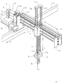
- the robot arm according to the invention comprises (FIG. 1) as a carrier a carriage 1, which is horizontal along a rail 2 runs in an x direction, can be pushed back and forth. In the simplest case, this can be done in a manner known per se by one controlled by a central control unit DC servo motor happen in carriage 1, which is a pinion drives which, directly or via a toothed belt a rack integrated into the rail 2 engages.
- a central control unit DC servo motor happen in carriage 1, which is a pinion drives which, directly or via a toothed belt a rack integrated into the rail 2 engages.
- the carriage 1 carries three arranged parallel to each other Support rods 3, 4, 5 that are horizontal in a y-direction protrude at right angles with the x direction includes. Their ends are in a common one End plate 6, which has a corner profile 7 on the carriage 1 attached, stored.
- the support rods 3, 4, 5 are in Carriage 1 immovable, but they are three independent of the central control unit DC servomotors 8, 9, 10 controllable from one another rotatable.
- a runner 11 is non-rotatable on the support rods 3, 4, 5 and suspended in the y direction. There are two in it along az direction, that with the x direction and the y direction each includes a right angle and is consequently vertical, on both sides of the support rods 3, 4, 5 continuous rods 12, 13 slidable and rotatable stored. They carry a gripper 14 at their lower end and are in one at the opposite top common yoke 15 stored.
- the gripper 14 has a upper gripper housing 16, which is immovable and suspended non-rotatably at the ends of the rods 12, 13 and with which a lower pliers housing 17, the one downward gripper tongs 18 carries, rotatably connected is.
- the gripper tongs 18 have two gripper fingers that to open and close the gripper pliers 18 against each other are movable.
- the same is used to shift the rotor 11 in the y direction on a run of a toothed belt, above the support rods 3, 4, 5 stretched parallel to the same closed strap 19 fastened, which over two Deflection rollers and a drive wheel 20 designed as a gear runs on the carriage 1 and on the end plate 6 stored deflection roller 21 is deflected.
- the driving wheel 20 is driven by a DC servo motor 22 which is controlled by the central control unit.
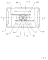
- the sliding gear includes furthermore two sliding wheels designed as gear wheels 24a, b (Fig. 2-4), which at the opposite ends of a double sleeve 25 are formed, which are rotatable in the rotor 11, but immovable and on the first one in the middle Support rod 3 is slidable, but is non-rotatably mounted.
- the storage on the support rod 3 is by a Ball bearing manufactured.
- the first support rod 3 has two diametrically opposite one another in the longitudinal direction continuous grooves on which rectified, in Longitudinally limited grooves on the inside of the first support rod 3 receiving through opening 26 of the Sleeve 25 are opposite.
- In the two of each other opposite grooves are formed channels several balls arranged, the diameter only slightly is below that of the canal, making it a positive fit Connection between the first support rod 3 and the sleeve 25 produce which with respect to mutual rotation of these Parts allows very little play, so that there are rotations the first support rod 3 with great precision on the sleeve 25 and thus transfer wheels 24a, b, but a displacement of the sleeve 25 along the support rod 3 only opposed very little resistance.
- the belt 23a is above (Fig. 2) via a left above of the sliding wheel 24a arranged first deflection roller 27 guided, then down around the sliding wheel 24a with which he intervenes and then below by a right above of the sliding wheel 24a arranged second deflection roller 28, which is the lateral distance of the belt 23a from the Carrier rods 3, 4, 5 sets. Because of this leadership of the Belt 23a engages it approximately at an angle 180 ° with the sliding wheel 24a, which is a slip-free Contact without local overloading of belt 23a ensures. The leadership of the belt 23b over the Shift wheel 24b is exactly the same.
- the gripper tongs 18 are opened and closed via a first angular gear in the rotor 11 and a Gripper gear in the gripper 14.
- the first angular gear sets rotations of the second support rod 4 in corresponding Rotations of the first rod 12 to. It includes (Fig. 3, 4) a first helical gear 29, which has a sleeve 30 on which is placed in the middle on the third support rod 4 is mounted and a second helical gear 31, which in same way via a sleeve 32 on the first rod 12 is stored.
- the helical gears 29, 31 stand engaged with each other.
- the sleeves 30, 32 are on the second support rod 4 or on the first runner 12 in stored exactly the same way as the sleeve 25 on the first Support rod 3.
- the gripper gear sets rotations of the first running rod 12 in corresponding opening and closing movements of the Gripper pliers 18 um. It includes (Fig. 5, 6) one nearby of the lower end of the first runner 12, as Gear wheel formed gripper wheel 33 and a gripper pinion 34, over which a closed toothed belt 35 runs.
- the Gripper pinion 34 is non-rotatably seated near its upper end on an axis of rotation 36 extending in the z direction gripper pin 37 rotatably mounted in the gripper housing 16, from the gripper housing 16, in which the previously mentioned parts of the gripper gear are arranged in the below pliers housing 17 protrudes where he on his lower end a first gear 38a and a second gear 38b wears.
- the gears 38a, b are of identical design - in particular, they have the same diameter - and attached coaxially and non-rotatably to the gripper pin 37, so that in their place also a single wider gear can be used.
- a first slide 39a and one are in the pliers housing 17 second slide 39b, which carry the gripper fingers 40a, b, Can be moved parallel to each other across the z-direction stored. They point out the gears lying between them 38a, b parallel straight flanks 41a, b to.
- a first one Toothed belt 42a is first on the gripper finger 40a lying front end of its flank 41a on the first Slider 39a attached and is up to the first gear 38a on the same. There it is redirected, whereby it passes over a Angle of 180 ° engages with the first gear 38a and then runs at the same at the rear end of the flank 41b of the second slide 39b, where it is attached to the same is.
- a second toothed belt runs in a corresponding manner 42b from the rear end of the flank 41a of the first slide 39a, where it is attached, adjacent to it until the second Gear 38b, where it also, but with the reverse Direction of rotation with respect to the axis of rotation 36 is deflected by 180 ° and further on the flank 41b of the second slide 39b to to the front end of the gripper finger 40b runs where it in turn is attached.
- the distance between the two flanks 41a, 41b just corresponds to that Diameter of the gears 38a, b and twice the thickness of the Timing belt 42a, b.
- the arrangement is, apart from that Height offset of the gears 38a, b and the toothed belt 42a, b, mirror-symmetrical with respect to the axis of rotation 36.
- a rotation of the pliers housing 17 relative to Gripper housing 16 takes place via a second angular gear in Runner 11 and a rotary gear in the gripper 14.
- the second Angular gear, the rotary movements of the third support rod 5 in corresponding rotary movements of the second running rod 13 is implemented (Fig. 3, 4) with a first helical gear 43, that on a sleeve mounted on the third support rod 5 44 sits and a second engaging with the same Helical gear 45 on one on the second running rod 13 mounted sleeve 46 constructed exactly the same as the first Angular gear.
- the rotary pinion 48 is non-rotatable with the Pliers housing 17 connected and coaxial with the gripper pin 37, through a central opening in the same the gripper pinion 34 connects to the gears 38a, b.
- the Rotary wheel 47 and rotary pinion 48 each have the same Diameter on like the gripper wheel 33 or the gripper pinion 34.
- the opening and closing of the gripper tongs 18 is carried out by Carriage 1 made from.
- About (Fig. 3) becomes the second Support rod 4 from the DC servo motor 9 in - from the End plate 6 seen here - turned counterclockwise, so this is from the first angular gear in rotor 11 in one proportional rotation of the first rod 12 im - from the yoke 15 seen here - implemented clockwise.
- This rotation divides in the gripper gear (Fig. 5) via the gripper wheel 33, the belt 35 and the gripper pinion 34 the gripper pin 37 with which it transmits to the gears 38a, b.
- the Clockwise rotation of the gears 38a and 38b (Fig.
- rotations of the gripper 18 from Carriage 1 causes by the third support rod 5 through the DC servo motor 10 is rotated.
- the Rotary gear (Fig. 5) sets this rotation via the rotary wheel 47, the toothed belt 49 and the rotating pinion 48 in one proportional rotation of the pliers housing 17.
- the rotation the second rod 13 is slightly reduced, because the diameter of the rotating pinion 48 is slightly larger than that of the rotary wheel 47.
- the gripper pin 37 must also be rotated become. This is done by an exactly corresponding one Compensating rotation of the first rod 12, which in exactly is reduced accordingly. Because the first Angular gear and the second angular gear exactly with each other correspond and also the same gear ratio, e.g. B. 1: 1, the balancing rotation of the Gripper pin 37 by one of the rotation of the second Support rod 4 in the rotation angle exactly corresponding and Direction of rotation opposite compensation rotation of the third Carrying rod 5 causes.
Abstract
Description
Die Erfindung betrifft einen Robotarm gemäss dem Oberbegriff des Anspruchs 1. Derartige Geräte werden beispielsweise zum Aus- und Einladen von Probenbehältern in Laborgeräten oder auch zur Handhabung und Montage von Komponenten an Montagebändern eingesetzt.The invention relates to a robot arm according to the preamble of claim 1. Such devices are for example Unloading and loading sample containers in laboratory equipment or also for the handling and assembly of components Assembly tapes used.
Gattungsgemässe Robotarme sind in vielen Ausführungen bekannt. Aus dem Propsekt 'Automatische Handhabungstechnologie' der Firma AFAG AG in CH-4950 Huttwil ist z. B. ein gattungsgemässer Robotarm bekannt, der aus zwei Linearmodulen und einem drehbaren Greifermodul zusammengesetzt ist. Die Module sind pneumatisch angetrieben, was jedoch die Auflösung und Genauigkeit, mit der bestimmte Positionen angefahren werden können, auf Werte beschränkt, die nicht für alle Anwendungen ausreichen. Die integrierten pneumatischen Antriebe erhöhen zudem das Gewicht der Module und erfordern pneumatische Verbindungen, die den Aufbau komplizieren.Generic robotic arms come in many designs known. From the prospect 'Automatic Handling technology 'from AFAG AG in CH-4950 Huttwil is z. B. a generic robotic arm known from two linear modules and a rotatable gripper module is composed. The modules are pneumatic driven, however, what the resolution and accuracy, with to certain positions to values limited, which are not sufficient for all applications. The integrated pneumatic drives also increase this Weight of the modules and require pneumatic connections, that complicate the setup.
Der Erfindung liegt die Aufgabe zu Grunde, einen Robotarm zu schaffen, der sehr genau, reproduzierbar und mit hoher Auflösung verfahr- und bewegbar ist. Diese Aufgabe wird durch die Merkmale im Kennzeichen des Anspruchs 1 gelöst. Der erfindungsgemässe Robotarm ist nicht nur sehr präzise steuerbar, sondern auch verhältnismässig einfach aufgebaut. The invention is based on the object of a robotic arm create that very accurately, reproducibly and with high Resolution is movable and movable. This task will solved by the features in the characterizing part of claim 1. The robot arm according to the invention is not only very precise controllable, but also relatively simple.
Alle Bewegungen mehrachsig bewegbarer Teile werden von Antrieben erzeugt, die in einem ortsfesten oder lediglich längs einer Achse verschiebbaren Träger untergebracht sind und mit mechanischen Mitteln auf die besagten Teile übertragen. Das Gewicht derselben, das z. T. zwangsläufig über längere Hebelarme auf andere Bestandteile wie Halterungen oder Lager einwirkt, kann daher durchwegs niedrig gehalten werden, da sie keine eigenen mitbewegten Antriebe zu enthalten brauchen. Pneumatische oder elektrische Verbindungen, die sonst oft störend und schwer unterzubringen sind, sind daher ebenfalls nicht erforderlich.All movements of multi-axis movable parts are from Drives generated in a fixed or only slidable along an axis are accommodated and by mechanical means on said parts transfer. The weight of the same, e.g. T. necessarily over longer lever arms on other components such as Brackets or bearings can therefore act consistently be kept low since they do not have their own moving parts Drives need to contain. Pneumatic or electrical connections that are otherwise often bothersome and difficult are therefore not to be accommodated required.
Im folgenden wird die Erfindung anhand von Figuren, welche lediglich ein Ausführungsbeispiel darstellen, näher erläutert. Es zeigen
- Fig. 1
- einen erfindungsgemässen Robotarm gemäss einem Ausführungsbeispiel in perspektivischer Darstellung,
- Fig. 2
- einen Bestandteil des erfindungsgemässen Robotarms gemäss Fig. 1 mit abgenommener Abdeckung,
- Fig. 3
- einen vertikalen Querschnitt durch den Bestandteil gemäss Fig. 2, längs III-III in Fig. 4,
- Fig. 4
- einen vertikalen Längsschnitt gemäss IV-IV in Fig. 3,
- Fig. 5
- einen vertikalen Längsschnitt durch einen weiteren Bestandteil des erfindungsgemässen Robotarms gemäss Fig. 1, längs V-V in Fig. 6 und
- Fig. 6
- einen Querschnitt durch den Bestandteil gemäss VI-VI in Fig. 5.
- Fig. 1
- a robot arm according to the invention according to an embodiment in a perspective view,
- Fig. 2
- 1 a component of the robot arm according to the invention according to FIG. 1 with the cover removed,
- Fig. 3
- 3 shows a vertical cross section through the component according to FIG. 2, along III-III in FIG. 4,
- Fig. 4
- 3 shows a vertical longitudinal section according to IV-IV in FIG. 3,
- Fig. 5
- a vertical longitudinal section through a further component of the robot arm according to the invention according to FIG. 1, along VV in Fig. 6 and
- Fig. 6
- a cross section through the component according to VI-VI in Fig. 5th
Der erfindungsgemässe Robotarm umfasst (Fig. 1) als Träger einen Wagen 1, welcher längs einer Schiene 2, die horizontal in einer x-Richtung verläuft, hin- und herverschiebbar ist. Dies kann im einfachsten Fall in an sich bekannter Weise durch einen von einer zentralen Steuereinheit gesteuerten Gleichstrom-Servomotor im Wagen 1 geschehen, der ein Ritzel antreibt, welches direkt oder über einen Zahnriemen mit einer in die Schiene 2 integrierten Zahnstange eingreift.The robot arm according to the invention comprises (FIG. 1) as a carrier a carriage 1, which is horizontal along a rail 2 runs in an x direction, can be pushed back and forth. In the simplest case, this can be done in a manner known per se by one controlled by a central control unit DC servo motor happen in carriage 1, which is a pinion drives which, directly or via a toothed belt a rack integrated into the rail 2 engages.
Der Wagen 1 trägt drei parallel untereinander angeordnete
Tragstangen 3, 4, 5, die horizontal in eine y-Richtung
ragen, die mit der x-Richtung einen rechten Winkel
einschliesst. Ihre Enden sind in einer gemeinsamen
Abschlussplatte 6, die über ein Eckprofil 7 am Wagen 1
befestigt ist, gelagert. Die Tragstangen 3, 4, 5 sind im
Wagen 1 unverschieblich gelagert, doch sind sie mittels
dreier von der zentralen Steuereinheit unabhängig
voneinander steuerbarer Gleichstrom-Servomotoren 8, 9, 10
drehbar.The carriage 1 carries three arranged parallel to each
An den Tragstangen 3, 4, 5 ist ein Läufer 11 unverdrehbar
und in y-Richtung verschiebbar aufgehängt. In ihm sind zwei
längs einer z-Richtung, die mit der x-Richtung und der y-Richtung
jeweils einen rechten Winkel einschliesst und
folglich vertikal ist, beidseits der Tragstangen 3, 4, 5
durchlaufende Laufstangen 12, 13 verschiebbar und drehbar
gelagert. Sie tragen an ihrem unteren Ende einen Greifer 14
und sind am entgegengesetzten oberen Ende in einem
gemeinsamen Joch 15 gelagert. Der Greifer 14 weist ein
oberes Greifergehäuse 16 auf, das unverschiebbar und
unverdrehbar an den Enden der Laufstangen 12, 13 aufgehängt
ist und mit welchem ein unteres Zangengehäuse 17, das eine
nach unten ragende Greiferzange 18 trägt, drehbar verbunden
ist. Die Greiferzange 18 weist zwei Greiferfinger auf, die
zum Oeffnen und Schliessen der Greiferzange 18 gegeneinander
verschiebbar sind.A
Zur Verschiebung des Läufers 11 in y-Richtung ist derselbe
an einem Trum eines als Zahnriemen ausgebildeten, oberhalb
der Tragstangen 3, 4, 5 parallel zu denselben gespannten
geschlossenen Riemens 19 festgemacht, welcher über zwei
Umlenkrollen und ein als Zahnrad ausgebildetes Treibrad 20
am Wagen 1 läuft und an einer an der Abschlussplatte 6
gelagerten Umlenkrolle 21 umgelenkt wird. Das Treibrad 20
wird von einem Gleichstrom-Servomotor 22 angetrieben, der
von der zentralen Steuereinheit gesteuert wird.The same is used to shift the
Die Verschiebung der Laufstangen 12, 13 und des Greifers 14
in z-Richtung, d. h. das Heben und Senken des Greifers
geschieht mittels eines Verschiebegetriebes, welches
Drehbewegungen der ersten Tragstange 3 in entsprechende
Verschiebebewegungen umsetzt. Es umfasst zwei wiederum als
Zahnriemen ausgebildete Riemen 23a,b, die neben den
Laufstangen 12, 13 und parallel zu denselben vom Greifer 14
zum Joch 15 gespannt sind, an welchen ihre entgegengesetzten
Enden jeweils befestigt sind. Das Verschiebegetriebe umfasst
weiterhin zwei als Zahnräder ausgebildete Verschieberäder
24a,b (Fig. 2-4), die an den entgegengesetzten Enden einer
doppelten Hülse 25 angeformt sind, die im Läufer 11 drehbar,
aber unverschiebbar und an der mittig angeordneten ersten
Tragstange 3 verschiebbar, aber unverdrehbar gelagert ist.The displacement of the
Die Lagerung an der Tragstange 3 ist durch ein
Gleitkugellager hergestellt. Die erste Tragstange 3 weist
zwei einander diametral gegenüberliegende in Längsrichtung
durchgehende Nuten auf, welchen gleichgerichtete, in
Längsrichtung begrenzte Nuten an der Innenseite der die
erste Tragstange 3 aufnehmenden Durchführungsöffnung 26 der
Hülse 25 gegenüberliegen. In den beiden jeweils von einander
gegenüberliegenden Nuten gebildeten Kanälen sind jeweils
mehrere Kugeln angeordnet, deren Durchmesser nur geringfügig
unter dem des Kanals liegt, so dass sie eine formschlüssige
Verbindung zwischen der ersten Tragstange 3 und der Hülse 25
herstellen, welche bezüglich gegenseitiger Verdrehung dieser
Teile nur sehr geringes Spiel zulässt, sodass sich Drehungen
der ersten Tragstange 3 mit grosser Präzision auf die Hülse
25 und damit die Verschieberäder 24a,b übertragen, aber
einer Verschiebung der Hülse 25 längs der Tragstange 3 nur
sehr wenig Widerstand entgegensetzt.The storage on the
Der Riemen 23a ist (Fig. 2) oben über eine links oberhalb
des Verschieberades 24a angeordnete erste Umlenkrolle 27
geführt, dann unten um das Verschieberad 24a, mit dem er
eingreift und anschliessend unten um eine rechts oberhalb
des Verschieberads 24a angeordnete zweite Umlenkrolle 28,
welche den seitlichen Abstand des Riemens 23a von den
Tragstangen 3, 4, 5 einstellt. Aufgrund dieser Führung des
Riemens 23a greift derselbe über einen Winkel von annähernd
180° mit dem Verschieberad 24a ein, was einen schlupffreien
Kontakt ohne lokale Ueberlastung des Riemens 23a
sicherstellt. Die Führung des Riemens 23b über das
Verschieberad 24b ist genau analog.The
Das Oeffnen und Schliessen der Greiferzange 18 erfolgt über
ein erstes Winkelgetriebe im Läufer 11 und ein
Greifergetriebe im Greifer 14. Das erste Winkelgetriebe
setzt Drehungen der zweiten Tragstange 4 in entsprechende
Drehungen der ersten Laufstange 12 um. Es umfasst (Fig. 3,
4) ein erstes Schraubenrad 29, das über eine Hülse 30, auf
die es mittig aufgesetzt ist, an der dritten Tragstange 4
gelagert ist und ein zweites Schraubenrad 31, das in
gleicher Weise über eine Hülse 32 an der ersten Laufstange
12 gelagert ist. Die Schraubenräder 29, 31 stehen
miteinander im Eingriff. Die Hülsen 30, 32 sind an der
zweiten Tragstange 4 bzw. an der ersten Laufstange 12 in
genau gleicher Weise gelagert wie die Hülse 25 an der ersten
Tragstange 3.The gripper tongs 18 are opened and closed via
a first angular gear in the
Das Greifergetriebe setzt Drehungen der ersten Laufstange 12
in entsprechende Oeffnungs- und Schliessbewegungen der
Greiferzange 18 um. Es umfasst (Fig. 5, 6) ein in der Nähe
des unteren Endes der ersten Laufstange 12 angeformtes, als
Zahnrad ausgebildetes Greiferrad 33 und ein Greiferritzel
34, über die ein geschlossener Zahnriemen 35 läuft. Das
Greiferritzel 34 sitzt nahe dessen oberem Ende unverdrehbar
auf einem um eine in z-Richtung verlaufende Drehachse 36
drehbar im Greifergehäuse 16 gelagerten Greiferbolzen 37,
der aus dem Greifergehäuse 16, in welchem die bisher
genannten Teile des Greifergetriebes angeordnet sind, in das
unten anschliessende Zangengehäuse 17 ragt, wo er an seinem
unteren Ende ein erstes Zahnrad 38a und ein zweites Zahnrad
38b trägt. Die Zahnräder 38a,b sind gleich ausgebildet -
insbesondere weisen sie gleichen Durchmesser auf - und
koaxial und unverdrehbar am Greiferbolzen 37 befestigt, so
dass an ihrer Stelle auch ein einziges breiteres Zahnrad
eingesetzt werden kann.The gripper gear sets rotations of the first running
Im Zangengehäuse 17 sind ein erster Schieber 39a und ein
zweiter Schieber 39b, welche die Greiferfinger 40a,b tragen,
parallel zueinander quer zur z-Richtung verschiebbar
gelagert. Sie weisen den zwischen ihnen liegenden Zahnrädern
38a,b parallele gerade Flanken 41a,b zu. Ein erster
Zahnriemen 42a ist an einem dem Greiferfinger 40a zunächst
liegenden Vorderende von dessen Flanke 41a am ersten
Schieber 39a befestigt und liegt bis zum ersten Zahnrad 38a
an derselben an. Dort wird er umgelenkt, wobei er über einen
Winkel von 180° mit dem ersten Zahnrad 38a eingreift und
läuft dann an derselben anliegend zum Hinterende der Flanke
41b des zweiten Schiebers 39b, wo er an demselben befestigt
ist.A
In ganz entsprechender Weise läuft ein zweiter Zahnriemen
42b vom Hinterende der Flanke 41a des ersten Schiebers 39a,
wo er befestigt ist, an derselben anliegend bis zum zweiten
Zahnrad 38b, wo er ebenfalls, allerdings mit umgekehrtem
Drehsinn bezüglich der Drehachse 36, um 180° umgelenkt wird
und weiter an der Flanke 41b des zweiten Schiebers 39b bis
zu deren dem Greiferfinger 40b zunächst liegenden Vorderende
läuft, wo er wiederum befestigt ist. Der Abstand zwischen
den beiden Flanken 41a, 41b entspricht gerade dem
Durchmesser der Zahnräder 38a,b und der doppelten Dicke der
Zahnriemen 42a,b. Die Anordnung ist, abgesehen von der
Höhenversetzung der Zahnräder 38a,b und der Zahnriemen
42a,b, bezüglich der Drehachse 36 spiegelsymmetrisch.A second toothed belt runs in a
Eine Verdrehung des Zangengehäuses 17 relativ zum
Greifergehäuse 16 erfolgt über ein zweites Winkelgetriebe im
Läufer 11 und ein Drehgetriebe im Greifer 14. Das zweite
Winkelgetriebe, das Drehbewegungen der dritten Tragstange 5
in entsprechende Drehbewegungen der zweiten Laufstange 13
umsetzt, ist (Fig. 3, 4) mit einem ersten Schraubenrad 43,
das auf einer an der dritten Tragstange 5 gelagerten Hülse
44 sitzt und einem mit demselben eingreifenden zweiten
Schraubenrad 45 auf einer an der zweiten Laufstange 13
gelagerten Hülse 46 genau gleich aufgebaut wie das erste
Winkelgetriebe.A rotation of the
Das Drehgetriebe setzt Drehbewegungen der zweiten Laufstange
13 in solche des Zangengehäuses 17 um, das um die gleiche
Drehachse 36 wie der Greiferbolzen 37 drehbar am
Greifergehäuse 16 gelagert ist. Es umfasst (Fig. 5) ein in
der Nähe des unteren Endes der zweiten Laufstange 13
angeformtes, als Zahnrad ausgebildetes Drehrad 47 und ein
Drehritzel 48, über die ein geschlossener Zahnriemen 49
läuft. Das Drehritzel 48 ist unverdrehbar mit dem
Zangengehäuse 17 verbunden und koaxial mit dem Greiferbolzen
37, der durch eine zentrale Oeffnung in demselben hindurch
das Greiferritzel 34 mit den Zahnrädern 38a,b verbindet. Das
Drehrad 47 und das Drehritzel 48 weisen jeweils gleichen
Durchmesser auf wie das Greiferrad 33 bzw. das Greiferritzel
34.The rotary gear sets rotary movements of the second running
Soll nun ein bestimmter, durch Werte X, Y, Z für die x-, y-
und z-Koordinaten gekennzeichneter Punkt von der
Greiferzange 18 angefahren werden, so wird (Fig. 1) der
Wagen 1 durch den entsprechenden Gleichstrom-Servomotor in
an sich bekannter Weise längs der Schiene 2 verfahren, bis
die x-Koordinate mit dem Sollwert X übereinstimmt. Die y-Koordinate
wird mit dem Sollwert Y in Uebereinstimmung
gebracht, indem durch den Gleichstrom-Servomotor 22 das
Treibrad 20 angetrieben und dadurch der Riemen 19 bewegt
wird, der den Läufer 11 mitnimmt und längs der Tragstangen
3, 4, 5 verschiebt. Die Einstellung der z-Koordinate auf den
Sollwert Z erfolgt schliesslich mittels des Gleichstrom-Servomotors
8, der die erste Tragstange 3 dreht, welche
dabei (Fig. 2) die Verschieberäder 24a,b im Läufer 11
mitnimmt. Dadurch werden die über die Verschieberäder
geführten Riemen 23a,b in z-Richtung verschoben und nehmen
den Greifer 14, die Laufstangen 12, 13 und das Joch 15 mit.If a certain value X, Y, Z for the x-, y-
and z coordinates marked point from the
Auch das Oeffnen und Schliessen der Greiferzange 18 wird vom
Wagen 1 aus bewerkstelligt. Wird etwa (Fig. 3) die zweite
Tragstange 4 vom Gleichstrom-Servomotor 9 im - von der
Abschlussplatte 6 her gesehen - Gegenuhrzeigersinn gedreht,
so wird dies vom ersten Winkelgetriebe im Läufer 11 in eine
proportionale Drehung der ersten Laufstange 12 im - vom Joch
15 her gesehen - Uhrzeigersinn umgesetzt. Diese Drehung
teilt sich im Greifergetriebe (Fig. 5) über das Greiferrad
33, den Riemen 35 und das Greiferritzel 34 dem Greiferbolzen
37 mit, der sie auf die Zahnräder 38a,b überträgt. Die
Drehung der Zahnräder 38a und 38b im Uhrzeigersinn wird
(Fig. 6) über den ersten Zahnriemen 42a in eine Bewegung des
zweiten Schiebers 39b nach rechts bzw. über den zweiten
Zahnriemen 42b in eine Bewegung des ersten Schiebers 39a
nach links umgesetzt, so dass sich die Greiferfinger 40a und
40b auseinanderbewegen und die Greiferzange 18 sich öffnet.
In entsprechender Weise führt eine entgegengesetzte Drehung
der zweiten Tragstange 4 durch den Gleichstrom-Servomotor 9
zu einer Schliessbewegung der Greiferzange 18. Die
Verschiebung der Greiferfinger 40a,b ist stets dem
Drehwinkel der zweiten Tragstange 4 proportional.The opening and closing of the gripper tongs 18 is carried out by
Carriage 1 made from. About (Fig. 3) becomes the
In ähnlicher Weise werden Drehungen der Greiferzange 18 vom
Wagen 1 aus bewirkt, indem die dritte Tragstange 5 durch den
Gleichstrom-Servomotor 10 gedreht wird. Eine Drehung im
Uhrzeigersinn wird (Fig. 3) durch das zweite Winkelgetriebe
im Läufer 11 in eine Drehung im Uhrzeigersinn der zweiten
Laufstange 13 von proportionalem Drehwinkel umgesetzt. Das
Drehgetriebe (Fig. 5) setzt diese Drehung über das Drehrad
47, den Zahnriemen 49 und das Drehritzel 48 in eine
proportionale Drehung des Zangengehäuses 17 um. Die Drehung
der zweiten Laufstange 13 wird dabei leicht untersetzt, da
der Durchmesser des Drehritzels 48 etwas grösser ist als
derjenige des Drehrades 47. Damit die Drehung des
Zangengehäuses 17 keine Verschiebung der Greiferfinger 40a,b
in demselben bewirkt, muss der Greiferbolzen 37 mitgedreht
werden. Dies geschieht durch eine genau entsprechende
Ausgleichsdrehung der ersten Laufstange 12, die in genau
entsprechender Weise untersetzt wird. Da das erste
Winkelgetriebe und das zweite Winkelgetriebe einander genau
entsprechen und auch das gleiche Uebersetzungsverhältnis,
z. B. 1:1 aufweisen, wird die Ausgleichsdrehung des
Greiferbolzens 37 durch eine der Drehung der zweiten
Tragstange 4 im Drehwinkel genau entsprechende und im
Drehsinn entgegengesetzte Ausgleichsdrehung der dritten
Tragstange 5 bewirkt. Similarly, rotations of the
Die beschriebenen Bewegungen, Verschiebung des Wagens 1 in
x-, des Läufers 11 in y- und des Greifers 14 in z-Richtung
sowie das Oeffnen und Schliessen sowie Drehen der
Greiferzange 18 können nacheinander oder bei geeigneter
zentraler Steuereinheit auch gleichzeitig ausgeführt werden.The movements described, moving the car 1 in
x, the
In der Ausbildung insbesondere einzelner Teile sind diverse Abwandlungen möglich, ohne dass der Rahmen der Erfindung verlassen würde. Beispielsweise können statt der Gleichstrom-Servomotoren auch andere steuer- oder regelbare Elektromotoren eingesetzt werden, insbesondere Schrittmotoren. Die Trag- und Laufstangen können anders ausgebildet sein als beschrieben, z. B. eine andere Zahl von Nuten aufweisen. Entscheidend ist, dass sie zur Uebertragung von Drehmomenten geeignet sind. Auch bei den Winkelgetrieben sind natürlich andere Ausführungen denkbar, etwa Schneckengetriebe.In the training of individual parts, in particular, are diverse Modifications possible without departing from the scope of the invention would leave. For example, instead of DC servomotors also other controllable or regulable Electric motors are used, in particular Stepper motors. The carrying and walking bars can be different be trained as described, e.g. B. another number of Have grooves. It is crucial that they are transferred of torques are suitable. Also with the angular gear other designs are of course conceivable, for example Worm gear.
- 11
- Wagendare
- 22nd
- Schienerail
- 3, 4, 53, 4, 5
- TragstangenSupport rods
- 66
- AbschlussplatteEnd plate
- 77
- EckprofilCorner profile
- 8, 9, 108, 9, 10
- Gleichstrom-ServomotorenDC servo motors
- 1111
- Läuferrunner
- 12, 1312, 13
- LaufstangenWalkways
- 1414
- GreiferGripper
- 1515
- Jochyoke
- 1616
- GreifergehäuseGripper housing
- 1717th
- ZangengehäusePliers housing
- 1818th
- GreiferzangeGripper pliers
- 1919th
- Riemenbelt
- 2020th
- TreibradDriving wheel
- 2121
- Umlenkrolle Pulley
- 2222
- Gleichstrom-ServomotorDC servo motor
- 23a, 23b23a, 23b
- Riemenbelt
- 24a, 24b24a, 24b
- VerschieberäderSliding wheels
- 2525th
- HülseSleeve
- 2626
- DurchführungsöffnungLead-through opening
- 27, 2827, 28
- UmlenkrollenPulleys
- 2929
- SchraubenradHelical gear
- 3030th
- HülseSleeve
- 3131
- SchraubenradHelical gear
- 3232
- HülseSleeve
- 3333
- GreiferradGripper wheel
- 3434
- GreiferritzelClaw pinion
- 3535
- ZahnriemenTiming belt
- 3636
- DrehachseAxis of rotation
- 3737
- GreiferbolzenGripper pin
- 38a, 38b38a, 38b
- ZahnräderGears
- 39a, 39b39a, 39b
- SchieberSlider
- 40a, 40b40a, 40b
- GreiferfingerGripper fingers
- 41a, 41b41a, 41b
- FlankenFlanks
- 42a, 42b42a, 42b
- ZahnriemenTiming belt
- 4343
- SchraubenradHelical gear
- 4444
- HülseSleeve
- 4545
- SchraubenradHelical gear
- 4646
- HülseSleeve
- 4747
- DrehradRotary knob
- 4848
- DrehritzelSprocket
- 4949
- ZahnriemenTiming belt
Claims (16)
Priority Applications (7)
| Application Number | Priority Date | Filing Date | Title |
|---|---|---|---|
| EP98119468A EP0995555A1 (en) | 1998-10-15 | 1998-10-15 | Robot arm |
| DE59908628T DE59908628D1 (en) | 1998-10-15 | 1999-10-05 | robot gripper |
| AT99810896T ATE260168T1 (en) | 1998-10-15 | 1999-10-05 | ROBOT GRIPPER |
| EP19990810896 EP0993916B1 (en) | 1998-10-15 | 1999-10-05 | Robot gripper |
| US09/415,554 US6264419B1 (en) | 1998-10-15 | 1999-10-08 | Robot arm |
| JP29213399A JP3916351B2 (en) | 1998-10-15 | 1999-10-14 | Robot arm |
| CA002286538A CA2286538C (en) | 1998-10-15 | 1999-10-14 | Robot arm |
Applications Claiming Priority (1)
| Application Number | Priority Date | Filing Date | Title |
|---|---|---|---|
| EP98119468A EP0995555A1 (en) | 1998-10-15 | 1998-10-15 | Robot arm |
Publications (1)
| Publication Number | Publication Date |
|---|---|
| EP0995555A1 true EP0995555A1 (en) | 2000-04-26 |
Family
ID=8232802
Family Applications (1)
| Application Number | Title | Priority Date | Filing Date |
|---|---|---|---|
| EP98119468A Withdrawn EP0995555A1 (en) | 1998-10-15 | 1998-10-15 | Robot arm |
Country Status (6)
| Country | Link |
|---|---|
| US (1) | US6264419B1 (en) |
| EP (1) | EP0995555A1 (en) |
| JP (1) | JP3916351B2 (en) |
| AT (1) | ATE260168T1 (en) |
| CA (1) | CA2286538C (en) |
| DE (1) | DE59908628D1 (en) |
Cited By (10)
| Publication number | Priority date | Publication date | Assignee | Title |
|---|---|---|---|---|
| WO2002027035A2 (en) * | 2000-09-28 | 2002-04-04 | Pangene Corporation | High-throughput gene cloning and phenotypic screening |
| US6466316B2 (en) | 1998-07-27 | 2002-10-15 | Ljl Biosystems, Inc. | Apparatus and methods for spectroscopic measurements |
| US6469311B1 (en) | 1997-07-16 | 2002-10-22 | Molecular Devices Corporation | Detection device for light transmitted from a sensed volume |
| US6483582B2 (en) | 1998-07-27 | 2002-11-19 | Ljl Biosystems, Inc. | Apparatus and methods for time-resolved spectroscopic measurements |
| US6498335B2 (en) | 1998-02-20 | 2002-12-24 | Ljl Biosystems, Inc. | Broad range light detection system |
| US6499366B1 (en) | 1997-07-16 | 2002-12-31 | Ljl Biosystems, Inc. | Sample feeder |
| US6576476B1 (en) | 1998-09-02 | 2003-06-10 | Ljl Biosystems, Inc. | Chemiluminescence detection method and device |
| US6825921B1 (en) | 1999-11-10 | 2004-11-30 | Molecular Devices Corporation | Multi-mode light detection system |
| WO2017198875A1 (en) | 2016-05-20 | 2017-11-23 | Andreas Hettich Gmbh & Co. Kg | Gripper |
| CN109153130A (en) * | 2016-05-13 | 2019-01-04 | 库卡德国有限公司 | Robot gripper with driving device |
Families Citing this family (72)
| Publication number | Priority date | Publication date | Assignee | Title |
|---|---|---|---|---|
| JP4035901B2 (en) * | 1998-10-09 | 2008-01-23 | 村田機械株式会社 | Plate material transfer device |
| CH698240B1 (en) * | 1998-11-17 | 2009-06-30 | Tecan Trading Ag | A method for weighing sample tubes, feeding and workstation. |
| US6802941B2 (en) * | 2001-01-18 | 2004-10-12 | Ovation Products Corporation | Distiller employing cyclical evaporation-surface wetting |
| JP2000296485A (en) * | 1999-04-15 | 2000-10-24 | Minolta Co Ltd | Micromanipulator |
| JP2001252954A (en) * | 2000-03-13 | 2001-09-18 | Star Seiki Co Ltd | Machine and method for taking out molding |
| DE10039062B4 (en) * | 2000-08-10 | 2007-02-01 | Schuler Pressen Gmbh & Co. Kg | Transfer press and a device for loading or. Unloading workpieces |
| GB0113985D0 (en) * | 2001-06-08 | 2001-08-01 | Quin Systems Ltd | Robotic devices |
| DE10261995B4 (en) * | 2002-01-27 | 2005-11-24 | Kendro Laboratory Products Gmbh | Object storage device |
| DE50211920D1 (en) * | 2002-07-02 | 2008-04-30 | Mueller Martini Holding Ag | Means for transporting a stack formed in a gathering machine standing upright from one another, lying on a support stack |
| US7228198B2 (en) * | 2002-08-09 | 2007-06-05 | Mckesson Automation Systems, Inc. | Prescription filling apparatus implementing a pick and place method |
| US7303094B2 (en) | 2002-08-09 | 2007-12-04 | Kevin Hutchinson | Vacuum pill dispensing cassette and counting machine |
| US7331967B2 (en) * | 2002-09-09 | 2008-02-19 | Hansen Medical, Inc. | Surgical instrument coupling mechanism |
| US20040084809A1 (en) * | 2002-11-05 | 2004-05-06 | Vanderploeg James A. | Side shuttle apparatus and method for an injection molding machine |
| EP1581445A4 (en) * | 2002-11-08 | 2009-04-22 | Irm Llc | Systems and methods of sorting samples |
| US8036774B2 (en) * | 2004-06-11 | 2011-10-11 | Ncr Corporation | Automated business system and method of vending and returning a consumer product |
| US7334978B2 (en) * | 2003-06-23 | 2008-02-26 | Hewlett-Packard Development Company, L.P. | Cartridge-handling apparatus for a media storage system |
| NL1023776C2 (en) * | 2003-06-30 | 2005-01-03 | Roboxis B V | Robot. |
| US7189047B2 (en) * | 2003-11-26 | 2007-03-13 | Tyco Electronics Power Systems, Inc. | Apparatus for moving a battery |
| JP2006232357A (en) * | 2005-02-25 | 2006-09-07 | Yuyama Manufacturing Co Ltd | Tablet-filling apparatus |
| JP2006255792A (en) * | 2005-03-15 | 2006-09-28 | Micron Seimitsu Kk | Workpiece transfer device for centerless grinding machine |
| FI20050422L (en) * | 2005-04-22 | 2006-10-23 | Lineartec Oy | Method and apparatus for making nail plate grids |
| US20060263270A1 (en) * | 2005-05-18 | 2006-11-23 | Beckman Coulter, Inc. | Robotic grip and twist assembly |
| CN100368157C (en) * | 2005-05-20 | 2008-02-13 | 中国科学院自动化研究所 | A force feedback provided manipulator |
| CN100400245C (en) * | 2006-08-02 | 2008-07-09 | 浙江大学 | Manipulator having cross-in/cross-out and retardation controller |
| CN101558311B (en) * | 2006-12-04 | 2012-02-08 | 英派克埃彼有限公司 | Container gripper provided with a position sensor |
| EP2095130B1 (en) * | 2006-12-04 | 2013-03-13 | Inpeco Holding Ltd | Container transfer apparatus with automatic positioning compensation |
| US7895930B2 (en) * | 2007-01-23 | 2011-03-01 | Foster-Miller, Inc. | Weapon mount |
| US20080181757A1 (en) * | 2007-01-26 | 2008-07-31 | Applied Robotics, Inc | Belt-driven robotic gripping device and method for operating |
| DE102008020622A1 (en) * | 2008-04-24 | 2009-10-29 | Krones Ag | Device and method for re-sorting piece goods compilations |
| DE102009043984A1 (en) * | 2009-09-11 | 2011-03-17 | Krones Ag | Gripping unit for holding and moving articles |
| JP4726152B1 (en) * | 2010-04-27 | 2011-07-20 | 藤原産業株式会社 | Suspended working robot and suspended working robot system |
| KR101190228B1 (en) * | 2010-05-06 | 2012-10-12 | 한국과학기술연구원 | Weight compensation mechanism and method using bevel gear and robot arm using the same |
| DE102010029809B4 (en) * | 2010-06-08 | 2012-04-19 | Schunk Gmbh & Co. Kg Spann- Und Greiftechnik | Handling unit for moving parts and method therefor |
| CN102371499A (en) * | 2010-08-09 | 2012-03-14 | 深圳富泰宏精密工业有限公司 | Clamping device for manipulator |
| CN102463535B (en) * | 2010-11-04 | 2013-11-20 | 鸿富锦精密工业(深圳)有限公司 | Holding mechanism |
| JP5993539B2 (en) | 2011-01-06 | 2016-09-14 | セイコーエプソン株式会社 | Robot hand and robot |
| JP5834480B2 (en) | 2011-05-11 | 2015-12-24 | セイコーエプソン株式会社 | Robot hand and robot |
| CN104647391B (en) * | 2011-06-28 | 2016-06-08 | 株式会社安川电机 | Robot and robot |
| DE102011108148A1 (en) * | 2011-07-20 | 2013-01-24 | M. Mohsen Saadat | Modular gripping mechanism for heavy loads |
| US9075031B2 (en) | 2011-10-11 | 2015-07-07 | Ortho-Clinical Diagnostics, Inc. | Apparatus for gripping and holding diagnostic cassettes |
| JP5983080B2 (en) * | 2012-06-20 | 2016-08-31 | セイコーエプソン株式会社 | Robot hand, robot, and gripping mechanism |
| JP6088791B2 (en) * | 2012-10-30 | 2017-03-01 | あおい精機株式会社 | Chucking device |
| CN104044913B (en) * | 2013-03-11 | 2016-08-24 | 鸿准精密模具(昆山)有限公司 | Pay-off |
| DE102013207179B4 (en) * | 2013-04-19 | 2018-01-11 | Schunk Gmbh & Co. Kg Spann- Und Greiftechnik | Gripper-Swivel Unit |
| JP5766767B2 (en) * | 2013-11-05 | 2015-08-19 | ファナック株式会社 | Robot hand and robot for gripping cylindrical object |
| CN103802121A (en) * | 2014-02-11 | 2014-05-21 | 喻铁军 | Positioning structure of clamp assembly |
| DE102015211017B4 (en) * | 2015-06-16 | 2017-06-14 | Trumpf Werkzeugmaschinen Gmbh + Co. Kg | Method for unloading a cut-free part of the workpiece, associated laser cutting machine and computer program product |
| EP3368907B1 (en) * | 2015-10-30 | 2021-09-08 | Thermo Fisher Scientific Oy | Gripper finger and gripper |
| JP6657826B2 (en) * | 2015-11-16 | 2020-03-04 | 株式会社デンソーウェーブ | Gripping device |
| CN106181976B (en) * | 2016-07-26 | 2019-02-15 | 温州职业技术学院 | Three inserted sheet automatic catching robot system of lamp holder |
| CN106742598B (en) * | 2017-01-11 | 2018-03-23 | 林植梅 | A kind of winter is with carry hand device |
| EP3367102A1 (en) * | 2017-02-23 | 2018-08-29 | Roche Diagnostics GmbH | Gripping device and sample container processing system |
| JP6876476B2 (en) | 2017-03-17 | 2021-05-26 | 株式会社東芝 | Holding mechanism, transfer device and handling robot system |
| DE102017209661A1 (en) * | 2017-04-28 | 2018-10-31 | Albrecht Bäumer GmbH & Co.KG Spezialmaschinenfabrik | Needle gripper for handling workpieces by means of gripping needles |
| WO2019144355A1 (en) * | 2018-01-25 | 2019-08-01 | 深圳市固胜智能科技有限公司 | Electric clamping jaw |
| RU2700348C1 (en) * | 2018-07-02 | 2019-09-16 | Федеральное государственное бюджетное образовательное учреждение высшего образования "Ярославский государственный технический университет" ФГБОУВО "ЯГТУ" | Manipulator gripping device |
| CN108817931B (en) * | 2018-08-28 | 2023-09-29 | 建华建材(中国)有限公司 | Automatic edge-closing screw equipment |
| CN109259935A (en) * | 2018-09-17 | 2019-01-25 | 林江 | It is a kind of to treat the wiping arrangement for injuring trauma infection contamination outside |
| EP3670115B1 (en) * | 2018-12-20 | 2021-10-20 | Tecan Trading Ag | Transmission module, gripper module with transmission module and gripper device with gripper module |
| IT201900000184A1 (en) * | 2019-01-08 | 2020-07-08 | Gimatic S R L | Against the wrist of robotic arms for operating tools |
| EP3748364B1 (en) * | 2019-06-05 | 2023-05-24 | Roche Diagnostics GmbH | Gripping device for handling sample containers and analytical instrument |
| CN110154004A (en) * | 2019-06-24 | 2019-08-23 | 恒进感应科技(十堰)股份有限公司 | A kind of planer-type row frame manipulator |
| US11198215B1 (en) | 2019-08-19 | 2021-12-14 | Joshua Scott | Robotic arm |
| US11267139B2 (en) * | 2019-09-24 | 2022-03-08 | Scinomix | Gripper for automated tube handling |
| CN111037534A (en) * | 2019-12-31 | 2020-04-21 | 广西职业技术学院 | Industrial robot based on visual perception and operation method thereof |
| US11590666B1 (en) * | 2020-03-27 | 2023-02-28 | Mckesson Corporation | Apparatuses and systems for the automated retrieval and transport of articles |
| CN112109107A (en) * | 2020-09-20 | 2020-12-22 | 江西骏川半导体设备有限公司 | Inclined arm manipulator |
| CN112273053B (en) * | 2020-11-27 | 2022-06-17 | 南宁学院 | Flexible passion fruit picking manipulator end effector |
| CN112643832B (en) * | 2020-12-14 | 2022-08-16 | 福建华森家具有限公司 | Automatic processing system and process for wooden furniture |
| CN114921660B (en) * | 2022-05-30 | 2023-11-03 | 哈尔滨工业大学 | Aluminum liquid refining device based on multi-degree-of-freedom mechanical arm |
| CN115781713B (en) * | 2022-12-09 | 2023-05-30 | 青岛拓普斯智能科技有限公司 | Mechanical arm for transplanting upright posts |
| CN115922753B (en) * | 2023-01-09 | 2023-06-30 | 郴州市海通电子有限公司 | Integrated mechanical arm |
Citations (6)
| Publication number | Priority date | Publication date | Assignee | Title |
|---|---|---|---|---|
| GB2179322A (en) * | 1985-08-19 | 1987-03-04 | Werkzeugmasch Okt Veb | Industrial robot for handling workpieces and tools |
| DE3806148A1 (en) * | 1987-02-27 | 1988-09-08 | Myotoku Kk | Industrial workpiece gripping device - has jaws which are constrained to move equal distances but in opposite directions |
| EP0371872A1 (en) * | 1988-11-29 | 1990-06-06 | Regie Nationale Des Usines Renault | Multiaxis robot |
| US5150937A (en) * | 1989-09-07 | 1992-09-29 | Canon Kabushiki Kaisha | Work pickup apparatus |
| FR2676955A1 (en) * | 1991-05-31 | 1992-12-04 | Faveyrial Maurice | Cartesian handling robot incorporating belt-driven transmission means |
| EP0700733A1 (en) * | 1994-09-10 | 1996-03-13 | INDA INDUSTRIEAUSRÜSTUNGEN GmbH | Apparatus for cleaning and/or deburring of workpieces by liquid jetting |
Family Cites Families (3)
| Publication number | Priority date | Publication date | Assignee | Title |
|---|---|---|---|---|
| US3076673A (en) * | 1962-01-16 | 1963-02-05 | Cullen Friestedt Company | Lifter mechanism with horizontally extensible jaw-supporting arms |
| US4005782A (en) * | 1974-03-04 | 1977-02-01 | Engineered Metal Products Company, Inc. | Picker |
| US4591198A (en) * | 1984-02-16 | 1986-05-27 | Monforte Robotics, Inc. | Robotic end effectors |
-
1998
- 1998-10-15 EP EP98119468A patent/EP0995555A1/en not_active Withdrawn
-
1999
- 1999-10-05 AT AT99810896T patent/ATE260168T1/en not_active IP Right Cessation
- 1999-10-05 DE DE59908628T patent/DE59908628D1/en not_active Expired - Lifetime
- 1999-10-08 US US09/415,554 patent/US6264419B1/en not_active Expired - Lifetime
- 1999-10-14 JP JP29213399A patent/JP3916351B2/en not_active Expired - Fee Related
- 1999-10-14 CA CA002286538A patent/CA2286538C/en not_active Expired - Fee Related
Patent Citations (6)
| Publication number | Priority date | Publication date | Assignee | Title |
|---|---|---|---|---|
| GB2179322A (en) * | 1985-08-19 | 1987-03-04 | Werkzeugmasch Okt Veb | Industrial robot for handling workpieces and tools |
| DE3806148A1 (en) * | 1987-02-27 | 1988-09-08 | Myotoku Kk | Industrial workpiece gripping device - has jaws which are constrained to move equal distances but in opposite directions |
| EP0371872A1 (en) * | 1988-11-29 | 1990-06-06 | Regie Nationale Des Usines Renault | Multiaxis robot |
| US5150937A (en) * | 1989-09-07 | 1992-09-29 | Canon Kabushiki Kaisha | Work pickup apparatus |
| FR2676955A1 (en) * | 1991-05-31 | 1992-12-04 | Faveyrial Maurice | Cartesian handling robot incorporating belt-driven transmission means |
| EP0700733A1 (en) * | 1994-09-10 | 1996-03-13 | INDA INDUSTRIEAUSRÜSTUNGEN GmbH | Apparatus for cleaning and/or deburring of workpieces by liquid jetting |
Cited By (14)
| Publication number | Priority date | Publication date | Assignee | Title |
|---|---|---|---|---|
| US6499366B1 (en) | 1997-07-16 | 2002-12-31 | Ljl Biosystems, Inc. | Sample feeder |
| US6469311B1 (en) | 1997-07-16 | 2002-10-22 | Molecular Devices Corporation | Detection device for light transmitted from a sensed volume |
| US6498335B2 (en) | 1998-02-20 | 2002-12-24 | Ljl Biosystems, Inc. | Broad range light detection system |
| US6466316B2 (en) | 1998-07-27 | 2002-10-15 | Ljl Biosystems, Inc. | Apparatus and methods for spectroscopic measurements |
| US6483582B2 (en) | 1998-07-27 | 2002-11-19 | Ljl Biosystems, Inc. | Apparatus and methods for time-resolved spectroscopic measurements |
| US6576476B1 (en) | 1998-09-02 | 2003-06-10 | Ljl Biosystems, Inc. | Chemiluminescence detection method and device |
| US6825921B1 (en) | 1999-11-10 | 2004-11-30 | Molecular Devices Corporation | Multi-mode light detection system |
| WO2002027035A2 (en) * | 2000-09-28 | 2002-04-04 | Pangene Corporation | High-throughput gene cloning and phenotypic screening |
| WO2002027035A3 (en) * | 2000-09-28 | 2003-08-28 | Pangene Corporation | High-throughput gene cloning and phenotypic screening |
| CN109153130A (en) * | 2016-05-13 | 2019-01-04 | 库卡德国有限公司 | Robot gripper with driving device |
| US11185995B2 (en) | 2016-05-13 | 2021-11-30 | Kuka Deutschland Gmbh | Robot gripper having a drive device |
| WO2017198875A1 (en) | 2016-05-20 | 2017-11-23 | Andreas Hettich Gmbh & Co. Kg | Gripper |
| DE102016109317A1 (en) * | 2016-05-20 | 2017-11-23 | Andreas Hettich Gmbh & Co. Kg | grab |
| US10751886B2 (en) | 2016-05-20 | 2020-08-25 | Andreas Hettich Gmbh & Co. Kg | Gripper gripper for translationally moving and rotating a laboratory vessel |
Also Published As
| Publication number | Publication date |
|---|---|
| ATE260168T1 (en) | 2004-03-15 |
| CA2286538C (en) | 2005-02-01 |
| US6264419B1 (en) | 2001-07-24 |
| DE59908628D1 (en) | 2004-04-01 |
| CA2286538A1 (en) | 2000-04-15 |
| JP2000117677A (en) | 2000-04-25 |
| JP3916351B2 (en) | 2007-05-16 |
Similar Documents
| Publication | Publication Date | Title |
|---|---|---|
| EP0995555A1 (en) | Robot arm | |
| EP0993916B1 (en) | Robot gripper | |
| DE112006001920B4 (en) | Parallel kinematic device with means for compensating the holding force | |
| EP1432885B1 (en) | Device for adjusting a window pane displaced by a double-stranded cable window lifter on a motor vehicle | |
| EP0241820A2 (en) | Injected part take-out device for injection-moulding machines | |
| DE2554873B2 (en) | Door with piano movement | |
| DE2844319C2 (en) | Tool change facility | |
| DE3819278A1 (en) | LINEAR GUIDE | |
| DE3326962A1 (en) | INDUSTRIAL ROBOT WITH TWO-PIECE JOINT ARM | |
| EP0898191A1 (en) | Coaxial drive for microscope sample holding stage | |
| DE3842182C1 (en) | ||
| DE3717957C2 (en) | ||
| DE102013112802B4 (en) | Robotic arm with flexible tension element | |
| EP1280622B1 (en) | Transfer device and method for controlling a transfer device | |
| DE10330581A1 (en) | Adjusting device for operational microscope, is connected to stand and has gear connected to chain or belt units which move on coupling plate | |
| DE3308474A1 (en) | Mechanism for moving objects while retaining a certain alignment | |
| DE2202005A1 (en) | Transfer device for picking up and transferring workpieces | |
| EP0782899A1 (en) | Machine-tool | |
| DE102005040715B4 (en) | Linear unit for lathes | |
| EP0920952B1 (en) | Pallet transfer apparatus | |
| DE968324C (en) | X-ray device with device parts arranged to be adjustable on a foldable patient bed with counterbalance | |
| DE202007010824U1 (en) | Device for the automatic removal of objects from containers | |
| DE3814771C2 (en) | ||
| DE102006046891A1 (en) | Workpiece transport device for assembly system, has gripper device provided for manipulating movement of workpiece holder and gripper base body with gripper arms running out orthogonal to axis of rotation | |
| DE2728471C3 (en) | Control arrangement for an active movable organ |
Legal Events
| Date | Code | Title | Description |
|---|---|---|---|
| PUAI | Public reference made under article 153(3) epc to a published international application that has entered the european phase |
Free format text: ORIGINAL CODE: 0009012 |
|
| AK | Designated contracting states |
Kind code of ref document: A1 Designated state(s): AT BE CH CY DE DK ES FI FR GB GR IE IT LI LU MC NL PT SE |
|
| AX | Request for extension of the european patent |
Free format text: AL;LT;LV;MK;RO;SI |
|
| AKX | Designation fees paid | ||
| STAA | Information on the status of an ep patent application or granted ep patent |
Free format text: STATUS: THE APPLICATION IS DEEMED TO BE WITHDRAWN |
|
| 18D | Application deemed to be withdrawn |
Effective date: 20001027 |
|
| REG | Reference to a national code |
Ref country code: DE Ref legal event code: 8566 |