EP0992219A1 - Embolic coil deployment system with retaining jaws - Google Patents
Embolic coil deployment system with retaining jaws Download PDFInfo
- Publication number
- EP0992219A1 EP0992219A1 EP99307799A EP99307799A EP0992219A1 EP 0992219 A1 EP0992219 A1 EP 0992219A1 EP 99307799 A EP99307799 A EP 99307799A EP 99307799 A EP99307799 A EP 99307799A EP 0992219 A1 EP0992219 A1 EP 0992219A1
- Authority
- EP
- European Patent Office
- Prior art keywords
- coil
- jaws
- heat responsive
- retaining
- embolic coil
- Prior art date
- Legal status (The legal status is an assumption and is not a legal conclusion. Google has not performed a legal analysis and makes no representation as to the accuracy of the status listed.)
- Granted
Links
- 230000003073 embolic effect Effects 0.000 title claims abstract description 40
- 239000000853 adhesive Substances 0.000 claims description 22
- 230000001070 adhesive effect Effects 0.000 claims description 22
- 238000010438 heat treatment Methods 0.000 claims description 20
- 230000008878 coupling Effects 0.000 claims description 13
- 238000010168 coupling process Methods 0.000 claims description 13
- 238000005859 coupling reaction Methods 0.000 claims description 13
- 239000004020 conductor Substances 0.000 claims description 12
- 230000005540 biological transmission Effects 0.000 claims description 7
- 230000003247 decreasing effect Effects 0.000 claims 1
- 230000004913 activation Effects 0.000 abstract 1
- 238000000034 method Methods 0.000 description 9
- 230000002792 vascular Effects 0.000 description 6
- 239000004831 Hot glue Substances 0.000 description 3
- 210000004204 blood vessel Anatomy 0.000 description 3
- 238000012986 modification Methods 0.000 description 3
- 230000004048 modification Effects 0.000 description 3
- 206010002329 Aneurysm Diseases 0.000 description 2
- 208000007536 Thrombosis Diseases 0.000 description 2
- 239000012530 fluid Substances 0.000 description 2
- 238000004519 manufacturing process Methods 0.000 description 2
- BASFCYQUMIYNBI-UHFFFAOYSA-N platinum Chemical compound [Pt] BASFCYQUMIYNBI-UHFFFAOYSA-N 0.000 description 2
- 210000005166 vasculature Anatomy 0.000 description 2
- 206010003226 Arteriovenous fistula Diseases 0.000 description 1
- 208000009443 Vascular Malformations Diseases 0.000 description 1
- 206010053648 Vascular occlusion Diseases 0.000 description 1
- 229910045601 alloy Inorganic materials 0.000 description 1
- 239000000956 alloy Substances 0.000 description 1
- 210000001367 artery Anatomy 0.000 description 1
- 230000015572 biosynthetic process Effects 0.000 description 1
- 239000008280 blood Substances 0.000 description 1
- 210000004369 blood Anatomy 0.000 description 1
- 238000010276 construction Methods 0.000 description 1
- 229940079593 drug Drugs 0.000 description 1
- 239000003814 drug Substances 0.000 description 1
- 239000000835 fiber Substances 0.000 description 1
- 239000003292 glue Substances 0.000 description 1
- PCHJSUWPFVWCPO-UHFFFAOYSA-N gold Chemical compound [Au] PCHJSUWPFVWCPO-UHFFFAOYSA-N 0.000 description 1
- 229910052737 gold Inorganic materials 0.000 description 1
- 239000010931 gold Substances 0.000 description 1
- 239000007788 liquid Substances 0.000 description 1
- 239000000463 material Substances 0.000 description 1
- 238000002483 medication Methods 0.000 description 1
- 239000002184 metal Substances 0.000 description 1
- 229910052751 metal Inorganic materials 0.000 description 1
- 239000007769 metal material Substances 0.000 description 1
- 150000002739 metals Chemical class 0.000 description 1
- 238000005065 mining Methods 0.000 description 1
- HLXZNVUGXRDIFK-UHFFFAOYSA-N nickel titanium Chemical compound [Ti].[Ti].[Ti].[Ti].[Ti].[Ti].[Ti].[Ti].[Ti].[Ti].[Ti].[Ni].[Ni].[Ni].[Ni].[Ni].[Ni].[Ni].[Ni].[Ni].[Ni].[Ni].[Ni].[Ni].[Ni] HLXZNVUGXRDIFK-UHFFFAOYSA-N 0.000 description 1
- 229910001000 nickel titanium Inorganic materials 0.000 description 1
- 229910052697 platinum Inorganic materials 0.000 description 1
- 230000001737 promoting effect Effects 0.000 description 1
- 239000012945 sealing adhesive Substances 0.000 description 1
- 229910000679 solder Inorganic materials 0.000 description 1
- WFKWXMTUELFFGS-UHFFFAOYSA-N tungsten Chemical compound [W] WFKWXMTUELFFGS-UHFFFAOYSA-N 0.000 description 1
- 229910052721 tungsten Inorganic materials 0.000 description 1
- 239000010937 tungsten Substances 0.000 description 1
- 208000021331 vascular occlusion disease Diseases 0.000 description 1
- 210000003462 vein Anatomy 0.000 description 1
- 238000012800 visualization Methods 0.000 description 1
Images


Classifications
-
- A—HUMAN NECESSITIES
- A61—MEDICAL OR VETERINARY SCIENCE; HYGIENE
- A61B—DIAGNOSIS; SURGERY; IDENTIFICATION
- A61B17/00—Surgical instruments, devices or methods, e.g. tourniquets
- A61B17/12—Surgical instruments, devices or methods, e.g. tourniquets for ligaturing or otherwise compressing tubular parts of the body, e.g. blood vessels, umbilical cord
- A61B17/12022—Occluding by internal devices, e.g. balloons or releasable wires
- A61B17/12131—Occluding by internal devices, e.g. balloons or releasable wires characterised by the type of occluding device
- A61B17/1214—Coils or wires
-
- A—HUMAN NECESSITIES
- A61—MEDICAL OR VETERINARY SCIENCE; HYGIENE
- A61B—DIAGNOSIS; SURGERY; IDENTIFICATION
- A61B17/00—Surgical instruments, devices or methods, e.g. tourniquets
- A61B17/30—Surgical pincettes without pivotal connections
-
- A—HUMAN NECESSITIES
- A61—MEDICAL OR VETERINARY SCIENCE; HYGIENE
- A61B—DIAGNOSIS; SURGERY; IDENTIFICATION
- A61B17/00—Surgical instruments, devices or methods, e.g. tourniquets
- A61B2017/00831—Material properties
- A61B2017/00862—Material properties elastic or resilient
-
- A—HUMAN NECESSITIES
- A61—MEDICAL OR VETERINARY SCIENCE; HYGIENE
- A61B—DIAGNOSIS; SURGERY; IDENTIFICATION
- A61B17/00—Surgical instruments, devices or methods, e.g. tourniquets
- A61B17/12—Surgical instruments, devices or methods, e.g. tourniquets for ligaturing or otherwise compressing tubular parts of the body, e.g. blood vessels, umbilical cord
- A61B17/12022—Occluding by internal devices, e.g. balloons or releasable wires
- A61B2017/1205—Introduction devices
- A61B2017/12054—Details concerning the detachment of the occluding device from the introduction device
- A61B2017/12063—Details concerning the detachment of the occluding device from the introduction device electrolytically detachable
-
- A—HUMAN NECESSITIES
- A61—MEDICAL OR VETERINARY SCIENCE; HYGIENE
- A61B—DIAGNOSIS; SURGERY; IDENTIFICATION
- A61B17/00—Surgical instruments, devices or methods, e.g. tourniquets
- A61B17/12—Surgical instruments, devices or methods, e.g. tourniquets for ligaturing or otherwise compressing tubular parts of the body, e.g. blood vessels, umbilical cord
- A61B17/12022—Occluding by internal devices, e.g. balloons or releasable wires
- A61B2017/1205—Introduction devices
- A61B2017/12054—Details concerning the detachment of the occluding device from the introduction device
- A61B2017/12068—Details concerning the detachment of the occluding device from the introduction device detachable by heat
- A61B2017/12077—Joint changing shape upon application of heat, e.g. bi-metal or reversible thermal memory
Definitions
- the present invention relates to a medical device for placing an embolic coil at a preselected location within a vessel of the human body, and more particularly, relates to a catheter having retaining jaws at the distal tip of the catheter for holding the embolic coil in order to transport the coil to a desired position within the vessel and a release mechanism for causing the jaws to open to thereby release the embolic coil at that position.
- Coils which are placed in vessels may take the form of helically wound coils, or alternatively, may be random wound coils, coils wound within other coils or many other such configurations. Examples of various coil configurations are disclosed in U.S. Patent No. 5,334,210, entitled, “Vascular Occlusion Assembly; U.S. Patent No. 5,382,259, entitled, "Vasoocclusion Coil With Attached Tubular Woven Or Braided Fibrous Coverings.” Embolic coils are generally formed of radiopaque metallic materials, such as platinum, gold, tungsten, or alloys of these metals. Often times, several coils are placed at a given location in order to occlude the flow of blood through the vessel by promoting thrombus formation at the particular location.
- embolic coils have been placed within the distal end of the catheter. When the distal end of the catheter is properly positioned the coil may then be pushed out of the end of the catheter with, for example, a guidewire to release the coil at the desired location. This procedure of placement of the embolic coil is conducted under fluoroscopic visualization such that the movement of the coil through the vasculature of the body may be monitored and the coil may be placed at the desired location. With these placements systems there is very little control over the exact placement of the coil since the coil may be ejected to a position some distance beyond the end of the catheter.
- Another coil positioning system utilizes a catheter having a socket at the distal end of the catheter for retaining a ball which is bonded to the proximal end of the coil.
- the ball which is larger in diameter than the outside diameter of the coil, is placed in a socket within the lumen at the distal end of the catheter and the catheter is then moved into a vessel in order to place the coil at a desired position.
- a pusher wire with a piston at the end thereof is pushed distally from the proximal end of the catheter to thereby push the ball out of the socket in order to release the coil at the desired position.
- Another method for placing an embolic coil is that of utilizing a heat releasable adhesive bond for retaining the coil at the distal end of the catheter.
- One such system uses laser energy which is transmitted through a fiber optic cable in order to apply heat to the adhesive bond in order to release the coil from the end of the catheter.
- Such a method is disclosed in U.S. Patent No. 5,108,407, entitled, "Method And Apparatus For Placement Of An Embolic Coil.”
- Such a system also suffers from the problem of having a separate, relatively stiff element which extends throughout the length of the catheter with resulting stiffness of the catheter.
- Still another method for placing an embolic coil is disclosed in co-pending U.S. Patent Application Serial No. 09/177,848, entitled, "Embolic Coil Hydraulic Deployment System,” filed on October 21, 1998 and assigned to the same assignee as the present patent application.
- This patent application discloses the use of fluid pressure which is applied to the distal tip of the catheter for expanding the lumen of the catheter in order to release the embolic coil.
- the present invention is directed toward a vascular occlusive coil deployment system for use in placing an embolic coil at a preselected site within a vessel which includes an elongated flexible positioning member having a lumen extending therethrough and having proximal and distal ends. Retaining jaws are affixed to the distal end of the positioning member. The retaining jaws have a closed position for gripping and retaining the embolic coil and an open position for releasing the coil. A heat responsive coupling member is bonded to the retaining jaws to hold the jaws in a closed position. The heat responsive coupling member exhibits the characteristic of softening and yielding upon being heated.
- a heating element is positioned in close proximity to the heat responsive coupling member and is adapted to be coupled to a source of energy by the use of a conductor which extends through the lumen in the delivery member.
- the heating element causes the heat responsive coupling to soften and stretch to allow the retaining jaws to move to the open position to thereby release the embolic coil at the preselected site.
- the retaining jaws are resiliently biased toward the open position, and are preferably resiliently biased outwardly, to thereby cause the embolic coil to be released when the coupling member becomes heated.
- the retaining jaws comprise two arms, which are preferably parallel to each other, which are resiliently biased outwardly.
- the heat responsive coupling member extends between the two arms and is bonded to the two arms for holding the jaws in a closed position.
- the heating element takes the form of a resistive heating coil, and preferably the resistively heating coil is wrapped around the outer surface of the heat responsive coupling member to thereby directly apply heat to the coupling member when the coil is energized.
- the energy transmission conductor takes the form of two electrical conductors which extend through the lumen of the delivery member and are connected to the resistive heating coil for applying electrical energy to the coil to thereby cause the coil to become heated.
- the heat responsive coupling member is comprised of a hot melt adhesive.
- Figure 1 generally illustrates a preferred embodiment of a vascular occlusive coil deployment system 10 of the present invention which is comprised of an elongated flexible catheter 12 which is utilized to position a coil deployment mechanism 14.
- a Luer connector 16 is connected to the proximal end of the catheter 12 and the coil deployment mechanism 14 is connected to a power supply 18 for applying energy to the coil deployment mechanism 14.
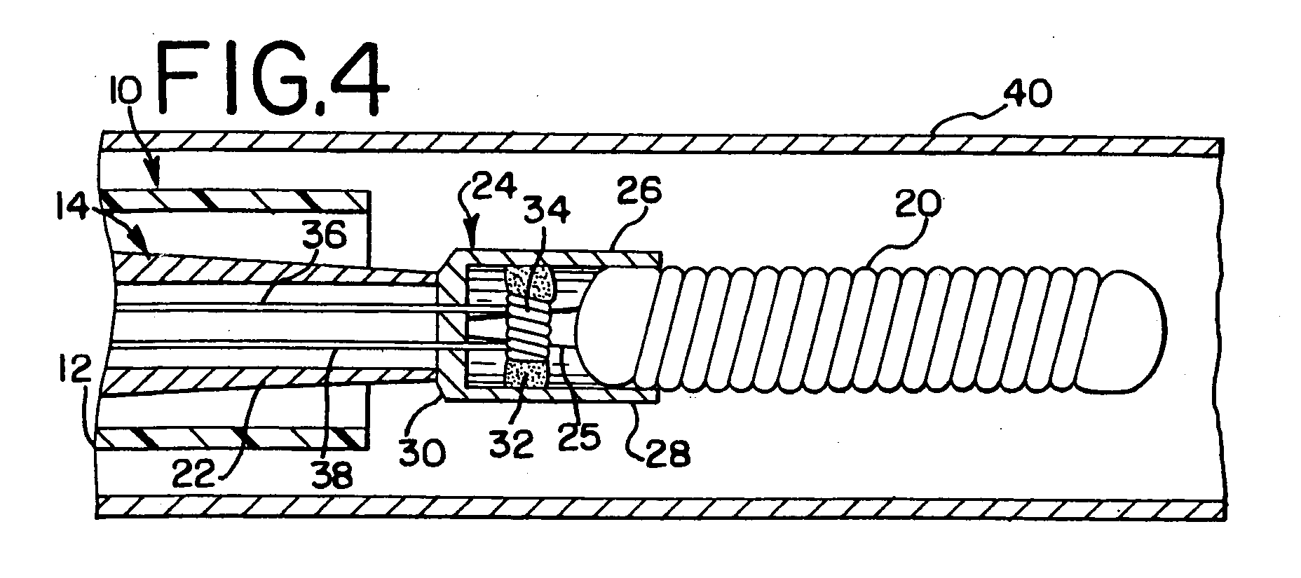
- FIG. 2 illustrates in more detail the construction of the coil deployment mechanism 14. More particularly, the deployment mechanism 14 includes an elongated tubular member 22 which is approximately the same length as the outer catheter 12 and which is slidably received by the catheter 12. The distal end of the tubular member 22 supports retaining jaws 24. The jaws 24 take the form of two parallel arms 26, 28 when in a extending from a mounting plate 30. As illustrated, the mounting plate 30 is fixedly attached to the distal tip of the tubular member 22. The parallel arms 26, 28 when in a closed position frictionally engage and tightly hold the embolic coil 20. The arms 26, 28 are held in the closed position by a heat softening adhesive 32 which extends between and is bonded to the parallel arms 26, 28.
- a heat softening adhesive 32 which extends between and is bonded to the parallel arms 26, 28.
- the parallel arms 26, 28 are normally biased outwardly so as to release the embolic coil 20, however, the heat softening adhesive 32 serves to hold the parallel arms in a closed position (as illustrated in Figure 2) to thereby frictionally engage and hold the proximal section of the embolic coil 20.
- the jaws preferably take the form of a cup formed from nitinol with a slot or notch 25 cut in opposing sidewalls from the opening of the cup to the bottom wall of the cup.
- the opposing wall, or arms 26, 28 are then bowed outwardly to the extent as shown in Figure 5 and the retaining jaws 24, are heat set at approximately 425 degrees centigrade for 30 minutes so as to form the retaining jaws 24 in a configuration similar to that shown in Figure 5.
- the arms 26, 28, which are resilient and are outwardly biased, are then pressured inwardly to tightly engage the embolic coil 20 and the heat softening adhesive 32 is heated and inserted between the arms 26, 28. When the adhesive 32 cools it serves to hold the arms 26, 27 in the closed position as shown in Figure 3.
- the heat sealing adhesive 32 may take the form of any biocompatible adhesive which, upon being heated, softens so that it may be stretched.
- this heat softening adhesive is comprised of a hot melt adhesive, such as, for example, a hot melt adhesive manufactured by Minnesota Mining and Manufacturing sold under the name Jet Melt, Catalog No. 3783-TC.
- the temperature required to soften this material is on the order of 63 degrees centigrade.
- a resistive heating element or coil 34 is wrapped around the heat softening adhesive 32 and is electrically coupled through a pair of conductors 36, 38 to the power supply 18. Accordingly, upon application of electrical current to the pair of conductors 36, 38, the resistive heating element 34 begins to heat to thereby cause the heat softening adhesive 32 to increase in temperature. As the adhesive 32 becomes warm it softens and the adhesive 32 softens and is permitted to stretch with the result that the outwardly biased arms 26, 28 move outwardly to release the embolic coil 20.
- the vascular occlusive coil deployment system 10 is inserted into a blood vessel 40 and is moved to a position within the blood vessel 40 to a position where it is desirable to place the embolic coil 20.
- the coil deployment mechanism 14 is pushed out of the distal end of the catheter 12 and electrical energy is then applied to the resistive heating coil 34 to thereby soften the adhesive 32.
- the outwardly biased parallel arms 26, 28 move from a closed position ( Figure 4)to an outwardly biased open position ( Figure 5). As the parallel arms open, there is no longer engagement between the parallel arms and the embolic coil 20 and the coil is released from the retaining jaws.
- the deployment mechanism may be activated by applying energy to a coil release mechanism to thereby cause the coil to be released and deposited at a desired location.
Abstract
Description
- The present invention relates to a medical device for placing an embolic coil at a preselected location within a vessel of the human body, and more particularly, relates to a catheter having retaining jaws at the distal tip of the catheter for holding the embolic coil in order to transport the coil to a desired position within the vessel and a release mechanism for causing the jaws to open to thereby release the embolic coil at that position.
- For many years flexible catheters have been used to place various devices within the vessels of the human body. Such devices include dilatation balloons, radiopaque fluids, liquid medications and various types of occlusion devices such as balloons and embolic coils. Examples of such catheter devices are disclosed in U.S. Patent No. 5,108,407, entitled "Method And Apparatus For Placement Of An Embolic Coil"; U.S. Patent No. 5,122,136, entitled, "Endovascular Electrolytically Detachable Guidewire Tip For The Electroformation Of Thrombus In Arteries, Veins, Aneurysms, Vascular Malformations And Arteriovenous Fistulas." These patents disclose devices for delivering embolic coils to preselected positions within vessel of the human body in order to treat aneurysms, or alternatively, to occlude the blood vessel at the particular location.
- Coils which are placed in vessels may take the form of helically wound coils, or alternatively, may be random wound coils, coils wound within other coils or many other such configurations. Examples of various coil configurations are disclosed in U.S. Patent No. 5,334,210, entitled, "Vascular Occlusion Assembly; U.S. Patent No. 5,382,259, entitled, "Vasoocclusion Coil With Attached Tubular Woven Or Braided Fibrous Coverings." Embolic coils are generally formed of radiopaque metallic materials, such as platinum, gold, tungsten, or alloys of these metals. Often times, several coils are placed at a given location in order to occlude the flow of blood through the vessel by promoting thrombus formation at the particular location.
- In the past, embolic coils have been placed within the distal end of the catheter. When the distal end of the catheter is properly positioned the coil may then be pushed out of the end of the catheter with, for example, a guidewire to release the coil at the desired location. This procedure of placement of the embolic coil is conducted under fluoroscopic visualization such that the movement of the coil through the vasculature of the body may be monitored and the coil may be placed at the desired location. With these placements systems there is very little control over the exact placement of the coil since the coil may be ejected to a position some distance beyond the end of the catheter.
- Numerous procedures have been developed to enable more accurate positioning of coils within a vessel. Still another such procedure involves the use of a glue, or solder, for attaching the embolic coil to a guidewire which, is in turn, placed within a flexible catheter for positioning the coil within the vessel at a preselected position. Once the coil is at the desired position, the coil is restrained by the catheter and the guidewire is pulled from the proximal end of the catheter to thereby cause the coil to become detached from the guidewire and released from the catheter system. Such a coil positioning system is disclosed in U.S. Patent 5,263,964, entitled, "Coaxial Traction Detachment Apparatus And Method."
- Another coil positioning system utilizes a catheter having a socket at the distal end of the catheter for retaining a ball which is bonded to the proximal end of the coil. The ball, which is larger in diameter than the outside diameter of the coil, is placed in a socket within the lumen at the distal end of the catheter and the catheter is then moved into a vessel in order to place the coil at a desired position. Once the position is reached, a pusher wire with a piston at the end thereof is pushed distally from the proximal end of the catheter to thereby push the ball out of the socket in order to release the coil at the desired position. Such a system is disclosed in U.S. Patent No. 5,350,397, entitled, "Axially Detachable Embolic Coil Assembly." One problem with this type of coil placement system which utilizes a pusher wire which extends through the entire length of the catheter and which is sufficiently stiff to push an attachment ball out of engagement with the socket at the distal end of the catheter is that the pusher wire inherently causes the catheter to be very stiff with the result that it is very difficult to guide the catheter through the vasculature of the body.
- Another method for placing an embolic coil is that of utilizing a heat releasable adhesive bond for retaining the coil at the distal end of the catheter. One such system uses laser energy which is transmitted through a fiber optic cable in order to apply heat to the adhesive bond in order to release the coil from the end of the catheter. Such a method is disclosed in U.S. Patent No. 5,108,407, entitled, "Method And Apparatus For Placement Of An Embolic Coil." Such a system also suffers from the problem of having a separate, relatively stiff element which extends throughout the length of the catheter with resulting stiffness of the catheter.
- Still another method for placing an embolic coil is disclosed in co-pending U.S. Patent Application Serial No. 09/177,848, entitled, "Embolic Coil Hydraulic Deployment System," filed on October 21, 1998 and assigned to the same assignee as the present patent application. This patent application discloses the use of fluid pressure which is applied to the distal tip of the catheter for expanding the lumen of the catheter in order to release the embolic coil.
- The present invention is directed toward a vascular occlusive coil deployment system for use in placing an embolic coil at a preselected site within a vessel which includes an elongated flexible positioning member having a lumen extending therethrough and having proximal and distal ends. Retaining jaws are affixed to the distal end of the positioning member. The retaining jaws have a closed position for gripping and retaining the embolic coil and an open position for releasing the coil. A heat responsive coupling member is bonded to the retaining jaws to hold the jaws in a closed position. The heat responsive coupling member exhibits the characteristic of softening and yielding upon being heated. A heating element is positioned in close proximity to the heat responsive coupling member and is adapted to be coupled to a source of energy by the use of a conductor which extends through the lumen in the delivery member. When energy is applied through the conductor to the heating element, the heating element causes the heat responsive coupling to soften and stretch to allow the retaining jaws to move to the open position to thereby release the embolic coil at the preselected site.
- In accordance with another aspect of the present invention, the retaining jaws are resiliently biased toward the open position, and are preferably resiliently biased outwardly, to thereby cause the embolic coil to be released when the coupling member becomes heated.
- In accordance with still another aspect of the present invention, the retaining jaws comprise two arms, which are preferably parallel to each other, which are resiliently biased outwardly. The heat responsive coupling member extends between the two arms and is bonded to the two arms for holding the jaws in a closed position.
- In accordance with still anther aspect of the present invention, the heating element takes the form of a resistive heating coil, and preferably the resistively heating coil is wrapped around the outer surface of the heat responsive coupling member to thereby directly apply heat to the coupling member when the coil is energized.
- In accordance with still another aspect of the present invention, the energy transmission conductor takes the form of two electrical conductors which extend through the lumen of the delivery member and are connected to the resistive heating coil for applying electrical energy to the coil to thereby cause the coil to become heated.
- In accordance with still a further aspect of the present invention, the heat responsive coupling member is comprised of a hot melt adhesive.
- These aspects of the invention and the advantages thereof will be more clearly understood from the following description and drawings of a preferred embodiment of the present invention:
-
- Figure 1 is an enlarged, partial sectional view of the vascular occlusive coil deployment system of the present invention;
- Figure 2 is an enlarged partially sectional view showing the coil deployment system prior to placement within a catheter; and,
- Figures 3 through 6 are enlarged partially sectional views illustrating the sequential steps of positioning the vascular coil within a vessel and releasing the coil at a preselected site.
-
- Figure 1 generally illustrates a preferred embodiment of a vascular occlusive
coil deployment system 10 of the present invention which is comprised of an elongatedflexible catheter 12 which is utilized to position acoil deployment mechanism 14. ALuer connector 16 is connected to the proximal end of thecatheter 12 and thecoil deployment mechanism 14 is connected to apower supply 18 for applying energy to thecoil deployment mechanism 14. - Figure 2 illustrates in more detail the construction of the
coil deployment mechanism 14. More particularly, thedeployment mechanism 14 includes an elongatedtubular member 22 which is approximately the same length as theouter catheter 12 and which is slidably received by thecatheter 12. The distal end of thetubular member 22 supports retainingjaws 24. Thejaws 24 take the form of twoparallel arms mounting plate 30. As illustrated, themounting plate 30 is fixedly attached to the distal tip of thetubular member 22. Theparallel arms embolic coil 20. Thearms parallel arms - As described, the
parallel arms embolic coil 20, however, the heat softening adhesive 32 serves to hold the parallel arms in a closed position (as illustrated in Figure 2) to thereby frictionally engage and hold the proximal section of theembolic coil 20. In the manufacture of theretaining jaws 24, the jaws preferably take the form of a cup formed from nitinol with a slot ornotch 25 cut in opposing sidewalls from the opening of the cup to the bottom wall of the cup. The opposing wall, orarms retaining jaws 24, are heat set at approximately 425 degrees centigrade for 30 minutes so as to form theretaining jaws 24 in a configuration similar to that shown in Figure 5. Thearms embolic coil 20 and the heat softening adhesive 32 is heated and inserted between thearms arms 26, 27 in the closed position as shown in Figure 3. - The
heat sealing adhesive 32 may take the form of any biocompatible adhesive which, upon being heated, softens so that it may be stretched. Preferably, this heat softening adhesive is comprised of a hot melt adhesive, such as, for example, a hot melt adhesive manufactured by Minnesota Mining and Manufacturing sold under the name Jet Melt, Catalog No. 3783-TC. The temperature required to soften this material is on the order of 63 degrees centigrade. - Also, as illustrated in Figure 2, a resistive heating element or
coil 34, is wrapped around theheat softening adhesive 32 and is electrically coupled through a pair ofconductors power supply 18. Accordingly, upon application of electrical current to the pair ofconductors resistive heating element 34 begins to heat to thereby cause theheat softening adhesive 32 to increase in temperature. As the adhesive 32 becomes warm it softens and the adhesive 32 softens and is permitted to stretch with the result that the outwardlybiased arms embolic coil 20. - More particularly, and as illustrated in Figures 3 through 6, the vascular occlusive
coil deployment system 10 is inserted into ablood vessel 40 and is moved to a position within theblood vessel 40 to a position where it is desirable to place theembolic coil 20. When thecatheter 12 has been positioned at a location slightly proximal of the preselected site for placement of the embolic coil (Figure 4), thecoil deployment mechanism 14 is pushed out of the distal end of thecatheter 12 and electrical energy is then applied to theresistive heating coil 34 to thereby soften the adhesive 32. Once the adhesive softens, the outwardly biasedparallel arms embolic coil 20 and the coil is released from the retaining jaws. - Finally, and as illustrated in Figure 6, the
coil deployment mechanism 14 is withdrawn back into thecatheter 12 and theembolic coil 20 remains in its deployed position. - With the vascular occlusive coil deployment system of the present invention it is possible to place an embolic coil very precisely at a desired location within a vessel. Once the coil has been placed in a preselected location by catheter, the deployment mechanism may be activated by applying energy to a coil release mechanism to thereby cause the coil to be released and deposited at a desired location.
- As is apparent, there are numerous modifications of the preferred embodiment described above which will become readily apparent to one skilled in the art, such as many variations and modifications of the deployment system including many different variations of the retaining jaws, many variations of energy sources for heating the adhesive, and many variations of heat softening adhesives.
- These modifications would be apparent to those having ordinary skill in the art to which this invention relates and are intended to be within the scope of the claims which follow.
Claims (7)
- A vasoocclusive coil detachment system for use in placing a coil at a preselected site within a vessel comprising:an elongated flexible positioning member having a lumen extending therethrough and having proximal and distal ends;an embolic coil;retaining jaws affixed to the distal end of the positioning member, said jaws having a closed position for gripping and retaining said embolic coil and an open position for releasing said embolic coil;an energy transmission conductor extending through the lumen of the delivery member and extending from the proximal end to the distal end of the delivery member;a heat responsive coupling member bonded to said retaining jaws to hold the jaws in the closed position, said heat responsive coupling member exhibits the characteristic of, upon being heated, softening thereby decreasing its tensile strength; and,a heating element mounted in close proximity to the heat responsive coupling member and being coupled to the energy transmission conductor whereby upon applying energy through the energy transmission conductor to the heating element, the heating element causes the heat responsive coupling member to soften and yield thereby causing the retaining jaws to move from the normally closed position to the open position to release the embolic coil at the preselected site.
- A vasoocclusive coil detachment system for use in placing a coil at a preselected site within a vessel comprising:an elongated flexible positioning member having a lumen extending therethrough and having proximal and distal ends;an embolic coil;retaining jaws affixed to the distal end of the positioning member, said jaws having a closed position for gripping and retaining said embolic coil and an open position for releasing said embolic coil;an energy transmission conductor extending through the lumen of the positioning member and extending from the proximal end of the positioning member to the distal end of the delivery member;a heat responsive adhesive member bonded to said retaining jaws to hold the jaws in the closed position, said heat responsive adhesive member exhibits the characteristic, upon being heated, of softening;a heating element mounted in close proximity to the heat responsive adhesive member and being coupled to the energy transmission conductor whereby upon applying energy through the energy transmission conductor to the heating element, the heating element causes the heat responsive adhesive member to soften and yield thereby causing the retaining jaws to move from the normally closed position to the open position to release the embolic coil at the preselected site.
- The system of claim 1 or claim 2, wherein the retaining jaws are resiliently biased toward the open position.
- The system of claim 1 or claim 2, wherein the retaining jaws are resiliently biased outwardly.
- The system of claim 3, wherein the retaining jaws comprise two arms which are resiliently biased outwardly and the heat responsive adhesive member extends between the two arms and is bonded to the two arms for holding the jaws in the closed position.
- The system of any one of claims 1 to 5, wherein the heating element comprises a resistive heating coil.
- The system of claim 6, wherein the resistive heating coil is wrapped around an outer surface of the heat responsive adhesive member.
Applications Claiming Priority (6)
| Application Number | Priority Date | Filing Date | Title |
|---|---|---|---|
| US10322498P | 1998-10-05 | 1998-10-05 | |
| US10309098P | 1998-10-05 | 1998-10-05 | |
| US103224P | 1998-10-05 | ||
| US103090P | 1998-10-05 | ||
| US399714 | 1999-09-21 | ||
| US09/399,714 US6277125B1 (en) | 1998-10-05 | 1999-09-21 | Embolic coil deployment system with retaining jaws |
Publications (2)
| Publication Number | Publication Date |
|---|---|
| EP0992219A1 true EP0992219A1 (en) | 2000-04-12 |
| EP0992219B1 EP0992219B1 (en) | 2002-12-18 |
Family
ID=27379468
Family Applications (1)
| Application Number | Title | Priority Date | Filing Date |
|---|---|---|---|
| EP99307799A Expired - Lifetime EP0992219B1 (en) | 1998-10-05 | 1999-10-04 | Embolic coil deployment system with retaining jaws |
Country Status (6)
| Country | Link |
|---|---|
| US (1) | US6277125B1 (en) |
| EP (1) | EP0992219B1 (en) |
| JP (1) | JP2000135219A (en) |
| AT (1) | ATE229773T1 (en) |
| CA (1) | CA2284458C (en) |
| DE (1) | DE69904548T2 (en) |
Cited By (7)
| Publication number | Priority date | Publication date | Assignee | Title |
|---|---|---|---|---|
| EP1738694A1 (en) * | 2005-06-30 | 2007-01-03 | Cordis Development Corporation | Chemically based deployment system with gripping feature for a vascular occlusion device |
| EP1743600A1 (en) * | 2005-06-30 | 2007-01-17 | Cordis Development Corporation | Chemically based deployment system for a vascular occlusion device |
| EP1825823A1 (en) * | 2006-02-28 | 2007-08-29 | Cordis Development Corporation | Heat-activated mechanical detachment system for delivery of a therapeutic device |
| EP2001543A2 (en) * | 2006-04-06 | 2008-12-17 | Cordis Development Corporation | Heat detachable coil |
| WO2014150824A1 (en) * | 2013-03-14 | 2014-09-25 | Stryker Corporation | Vaso-occlusive device delivery system |
| EP2944278A3 (en) * | 2014-05-13 | 2015-11-25 | NDI TIP Teknolojileri Anonim Sirketi | Retractable and rapid disconnect, floating diameter embolic coil product and delivery system |
| EP2967573B1 (en) * | 2013-03-14 | 2021-04-21 | Stryker Corporation | Vaso-occlusive device delivery system |
Families Citing this family (93)
| Publication number | Priority date | Publication date | Assignee | Title |
|---|---|---|---|---|
| US6494884B2 (en) * | 2001-02-09 | 2002-12-17 | Concentric Medical, Inc. | Methods and devices for delivering occlusion elements |
| US10258340B2 (en) * | 2001-11-09 | 2019-04-16 | DePuy Synthes Products, Inc. | Reloadable sheath for catheter system for deploying vasoocclusive devices |
| DE10233085B4 (en) | 2002-07-19 | 2014-02-20 | Dendron Gmbh | Stent with guide wire |
| US8425549B2 (en) | 2002-07-23 | 2013-04-23 | Reverse Medical Corporation | Systems and methods for removing obstructive matter from body lumens and treating vascular defects |
| KR100423860B1 (en) * | 2002-08-19 | 2004-03-22 | 규 호 이 | Assembly for embolic treatments |
| US7208003B2 (en) * | 2002-09-20 | 2007-04-24 | Cordis Neurovascular, Inc. | Reattachable introducer for a medical device deployment system |
| US7092765B2 (en) * | 2002-09-23 | 2006-08-15 | Medtronic, Inc. | Non-sheath based medical device delivery system |
| AU2004241111B2 (en) | 2003-05-15 | 2010-05-27 | Dsm Ip Assets B.V | Manufacture and use of implantable reticulated elastomeric matrices |
| DE602004008301T2 (en) | 2003-07-03 | 2008-05-08 | Cook Inc., Bloomington | CLOSING DEVICE FOR OCKLUDING THE LIQUID FLOW THROUGH A BODY VESSEL |
| US20050065501A1 (en) * | 2003-09-23 | 2005-03-24 | Scimed Life Systems, Inc. | Energy activated vaso-occlusive devices |
| US7789891B2 (en) * | 2003-09-23 | 2010-09-07 | Boston Scientific Scimed, Inc. | External activation of vaso-occlusive implants |
| US7419498B2 (en) * | 2003-10-21 | 2008-09-02 | Nmt Medical, Inc. | Quick release knot attachment system |
| US20050149108A1 (en) * | 2003-12-17 | 2005-07-07 | Microvention, Inc. | Implant delivery and detachment system and method |
| US7763077B2 (en) | 2003-12-24 | 2010-07-27 | Biomerix Corporation | Repair of spinal annular defects and annulo-nucleoplasty regeneration |
| EP1793743B1 (en) | 2004-09-22 | 2009-11-18 | Dendron GmbH | Micro-spiral implantation device |
| US7879064B2 (en) | 2004-09-22 | 2011-02-01 | Micro Therapeutics, Inc. | Medical implant |
| US8795315B2 (en) | 2004-10-06 | 2014-08-05 | Cook Medical Technologies Llc | Emboli capturing device having a coil and method for capturing emboli |
| JP2006181088A (en) * | 2004-12-27 | 2006-07-13 | Kyoto Univ | Medical wire |
| US8945169B2 (en) | 2005-03-15 | 2015-02-03 | Cook Medical Technologies Llc | Embolic protection device |
| US8221446B2 (en) | 2005-03-15 | 2012-07-17 | Cook Medical Technologies | Embolic protection device |
| US8025668B2 (en) * | 2005-04-28 | 2011-09-27 | C. R. Bard, Inc. | Medical device removal system |
| US7850708B2 (en) | 2005-06-20 | 2010-12-14 | Cook Incorporated | Embolic protection device having a reticulated body with staggered struts |
| US8109962B2 (en) | 2005-06-20 | 2012-02-07 | Cook Medical Technologies Llc | Retrievable device having a reticulation portion with staggered struts |
| US20070010848A1 (en) * | 2005-07-11 | 2007-01-11 | Andrea Leung | Systems and methods for providing cavities in interior body regions |
| US7766934B2 (en) | 2005-07-12 | 2010-08-03 | Cook Incorporated | Embolic protection device with an integral basket and bag |
| US7771452B2 (en) | 2005-07-12 | 2010-08-10 | Cook Incorporated | Embolic protection device with a filter bag that disengages from a basket |
| US8187298B2 (en) | 2005-08-04 | 2012-05-29 | Cook Medical Technologies Llc | Embolic protection device having inflatable frame |
| US8377092B2 (en) | 2005-09-16 | 2013-02-19 | Cook Medical Technologies Llc | Embolic protection device |
| US8632562B2 (en) | 2005-10-03 | 2014-01-21 | Cook Medical Technologies Llc | Embolic protection device |
| US8182508B2 (en) | 2005-10-04 | 2012-05-22 | Cook Medical Technologies Llc | Embolic protection device |
| US8252017B2 (en) | 2005-10-18 | 2012-08-28 | Cook Medical Technologies Llc | Invertible filter for embolic protection |
| US8216269B2 (en) | 2005-11-02 | 2012-07-10 | Cook Medical Technologies Llc | Embolic protection device having reduced profile |
| US7955354B2 (en) * | 2005-11-14 | 2011-06-07 | Occlutech Gmbh | Occlusion device and surgical instrument and method for its implantation/explantation |
| US8152831B2 (en) | 2005-11-17 | 2012-04-10 | Cook Medical Technologies Llc | Foam embolic protection device |
| EP1959873B1 (en) | 2005-12-13 | 2015-05-20 | Codman & Shurtleff, Inc. | Detachment actuator for use with medical device deployment systems |
| US7942894B2 (en) * | 2006-01-31 | 2011-05-17 | Codman & Shurtleff, Inc. | Embolic device delivery system |
| US7766933B2 (en) * | 2006-03-31 | 2010-08-03 | Codman & Shurtleff, Inc. | Stretch resistant design for embolic coils with stabilization bead |
| US7553321B2 (en) * | 2006-03-31 | 2009-06-30 | Cordis Development Corporation | Chemically based vascular occlusion device deployment |
| JP5230602B2 (en) | 2006-04-17 | 2013-07-10 | タイコ ヘルスケア グループ リミテッド パートナーシップ | System and method for mechanically positioning an endovascular implant |
| US8777979B2 (en) | 2006-04-17 | 2014-07-15 | Covidien Lp | System and method for mechanically positioning intravascular implants |
| US20070299461A1 (en) * | 2006-06-21 | 2007-12-27 | Boston Scientific Scimed, Inc. | Embolic coils and related components, systems, and methods |
| US8366720B2 (en) | 2006-07-31 | 2013-02-05 | Codman & Shurtleff, Inc. | Interventional medical device system having an elongation retarding portion and method of using the same |
| US8062325B2 (en) | 2006-07-31 | 2011-11-22 | Codman & Shurtleff, Inc. | Implantable medical device detachment system and methods of using the same |
| US20080071307A1 (en) | 2006-09-19 | 2008-03-20 | Cook Incorporated | Apparatus and methods for in situ embolic protection |
| US20080269774A1 (en) | 2006-10-26 | 2008-10-30 | Chestnut Medical Technologies, Inc. | Intracorporeal Grasping Device |
| US9901434B2 (en) | 2007-02-27 | 2018-02-27 | Cook Medical Technologies Llc | Embolic protection device including a Z-stent waist band |
| KR20100015521A (en) | 2007-03-13 | 2010-02-12 | 마이크로 테라퓨틱스 인코포레이티드 | An implant, a mandrel, and a method of forming an implant |
| JP5249249B2 (en) | 2007-03-13 | 2013-07-31 | コヴィディエン リミテッド パートナーシップ | Implant including a coil and a stretch resistant member |
| JP5308631B2 (en) * | 2007-04-04 | 2013-10-09 | テルモ株式会社 | catheter |
| US20100121350A1 (en) * | 2007-04-12 | 2010-05-13 | Greg Mirigian | Instantaneous mechanical detachment mechanism for vaso-occlusive devices |
| US8252018B2 (en) | 2007-09-14 | 2012-08-28 | Cook Medical Technologies Llc | Helical embolic protection device |
| US9138307B2 (en) | 2007-09-14 | 2015-09-22 | Cook Medical Technologies Llc | Expandable device for treatment of a stricture in a body vessel |
| US8419748B2 (en) | 2007-09-14 | 2013-04-16 | Cook Medical Technologies Llc | Helical thrombus removal device |
| US8088140B2 (en) | 2008-05-19 | 2012-01-03 | Mindframe, Inc. | Blood flow restorative and embolus removal methods |
| US11337714B2 (en) | 2007-10-17 | 2022-05-24 | Covidien Lp | Restoring blood flow and clot removal during acute ischemic stroke |
| US20090275971A1 (en) * | 2007-10-30 | 2009-11-05 | Boston Scientific Scimed, Inc. | Energy activated preloaded detachment mechanisms for implantable devices |
| AU2008345596B2 (en) * | 2007-12-21 | 2013-09-05 | Microvention, Inc. | A system and method of detecting implant detachment |
| BRPI0908500A8 (en) | 2008-02-22 | 2018-10-23 | Micro Therapeutics Inc | imaging methods of restoration of thrombus-occluded blood vessel blood flow, partial or substantial dissolution and thrombus dislocation, self-expanding thrombus removal equipment and integrated removable thrombus mass |
| AU2009303677B2 (en) * | 2008-10-13 | 2014-04-24 | Stryker European Holdings I, Llc | Vaso-occlusive coil delivery system |
| US8388644B2 (en) | 2008-12-29 | 2013-03-05 | Cook Medical Technologies Llc | Embolic protection device and method of use |
| JP2012520134A (en) * | 2009-03-13 | 2012-09-06 | ストライカー コーポレイション | Electrical contacts for closure device delivery systems |
| ES2715077T3 (en) | 2009-04-06 | 2019-05-31 | Stryker Corp | Supply wire for the occlusive device supply system |
| US8398671B2 (en) * | 2009-04-16 | 2013-03-19 | Stryker Corporation | Electrical contact for occlusive device delivery system |
| US20100268251A1 (en) * | 2009-04-16 | 2010-10-21 | Boston Scientific Scimed, Inc. | Delivery wire for occlusive device delivery system and method of manufacture |
| US9314250B2 (en) | 2009-04-16 | 2016-04-19 | Stryker Corporation | Electrical contact for occlusive device delivery system |
| US20110118776A1 (en) * | 2009-11-18 | 2011-05-19 | Boston Scientific Scimed, Inc. | Delivery wire assembly for occlusive device delivery system |
| US9039749B2 (en) | 2010-10-01 | 2015-05-26 | Covidien Lp | Methods and apparatuses for flow restoration and implanting members in the human body |
| US9579104B2 (en) | 2011-11-30 | 2017-02-28 | Covidien Lp | Positioning and detaching implants |
| US9011480B2 (en) | 2012-01-20 | 2015-04-21 | Covidien Lp | Aneurysm treatment coils |
| US9687245B2 (en) | 2012-03-23 | 2017-06-27 | Covidien Lp | Occlusive devices and methods of use |
| US9808255B2 (en) * | 2012-03-30 | 2017-11-07 | DePuy Synthes Products, Inc. | Embolic coil detachment mechanism with flexible distal member, resistive electrical heating element and shape memory polymer element |
| EP2967576B1 (en) * | 2013-03-15 | 2023-02-15 | Covidien LP | Delivery and detachment mechanisms for vascular implants |
| US10076399B2 (en) | 2013-09-13 | 2018-09-18 | Covidien Lp | Endovascular device engagement |
| GB201318403D0 (en) * | 2013-10-17 | 2013-12-04 | Cook Medical Technologies Llc | Release mechanism |
| US9713475B2 (en) | 2014-04-18 | 2017-07-25 | Covidien Lp | Embolic medical devices |
| US10271852B2 (en) * | 2014-05-13 | 2019-04-30 | Ndi Tip Teknolojileri Anonim Sirketi | Spring for moveable jaws of device and delivery system for releasing therapeutic appliance |
| GB2533087B (en) | 2014-12-08 | 2018-08-08 | Cook Medical Technologies Llc | Medical implant detachment mechanism and introducer assembly |
| US10245072B2 (en) | 2015-07-10 | 2019-04-02 | Medtronic, Inc. | Extravascular medical access tools having boring tip and methods of using such tools |
| US10758729B2 (en) | 2015-10-01 | 2020-09-01 | Medtronic, Inc. | Interventional medical systems, catheters, and methods |
| US10434283B2 (en) | 2015-10-29 | 2019-10-08 | Medtronic, Inc. | Interventional medical systems, associated assemblies and methods |
| US10080888B2 (en) | 2015-11-16 | 2018-09-25 | Medtronic, Inc. | Interventional medical systems and associated methods |
| US10531876B2 (en) | 2016-05-31 | 2020-01-14 | Spartan Micro, Inc. | Systems and methods for delivering intravascular implants |
| US9968360B2 (en) * | 2016-05-31 | 2018-05-15 | Spartan Micro, Inc. | Systems and methods for delivering intravascular implants |
| US10238864B2 (en) | 2016-07-29 | 2019-03-26 | Medtronic, Inc. | Interventional medical systems and associated tethering assemblies and methods |
| JP6946450B2 (en) | 2017-03-13 | 2021-10-06 | ボストン サイエンティフィック サイムド,インコーポレイテッドBoston Scientific Scimed,Inc. | Occlusion medical device system |
| US11376039B2 (en) | 2017-03-30 | 2022-07-05 | Medtronic, Inc. | Interventional medical systems and associated assemblies |
| WO2019027966A1 (en) | 2017-07-31 | 2019-02-07 | Boston Scientific Scimed, Inc. | Dilator with engagement region |
| EP3668419B1 (en) | 2017-08-15 | 2024-04-03 | Boston Scientific Scimed, Inc. | Occlusive medical device system |
| US10874402B2 (en) | 2017-10-10 | 2020-12-29 | Boston Scientific Scimed, Inc. | Detachable RF energized occlusive device |
| CN111670021B (en) | 2018-02-01 | 2023-08-04 | 波士顿科学国际有限公司 | Medical device release system |
| US11284902B2 (en) | 2018-02-01 | 2022-03-29 | Boston Scientific Scimed, Inc. | Method of making a vascular occlusion device |
| EP3927286A1 (en) * | 2019-02-19 | 2021-12-29 | Boston Scientific Scimed Inc. | Electronic control of medical device deployment systems |
| US11672946B2 (en) | 2019-09-24 | 2023-06-13 | Boston Scientific Scimed, Inc. | Protection and actuation mechanism for controlled release of implantable embolic devices |
Citations (10)
| Publication number | Priority date | Publication date | Assignee | Title |
|---|---|---|---|---|
| US5108407A (en) | 1990-06-08 | 1992-04-28 | Rush-Presbyterian St. Luke's Medical Center | Method and apparatus for placement of an embolic coil |
| US5122136A (en) | 1990-03-13 | 1992-06-16 | The Regents Of The University Of California | Endovascular electrolytically detachable guidewire tip for the electroformation of thrombus in arteries, veins, aneurysms, vascular malformations and arteriovenous fistulas |
| US5263964A (en) | 1992-05-06 | 1993-11-23 | Coil Partners Ltd. | Coaxial traction detachment apparatus and method |
| US5334210A (en) | 1993-04-09 | 1994-08-02 | Cook Incorporated | Vascular occlusion assembly |
| US5350397A (en) | 1992-11-13 | 1994-09-27 | Target Therapeutics, Inc. | Axially detachable embolic coil assembly |
| US5382259A (en) | 1992-10-26 | 1995-01-17 | Target Therapeutics, Inc. | Vasoocclusion coil with attached tubular woven or braided fibrous covering |
| EP0717961A1 (en) * | 1994-12-22 | 1996-06-26 | Target Therapeutics, Inc. | Implant delivery method and assembly |
| WO1997001368A1 (en) * | 1995-06-26 | 1997-01-16 | Trimedyne, Inc. | Therapeutic appliance releasing device |
| US5722989A (en) * | 1995-05-22 | 1998-03-03 | The Regents Of The University Of California | Microminiaturized minimally invasive intravascular micro-mechanical systems powered and controlled via fiber-optic cable |
| WO1999002094A1 (en) * | 1997-07-14 | 1999-01-21 | Boston Scientific Limited | Detachable vasoocclusive member using thermoadhesive junction |
Family Cites Families (12)
| Publication number | Priority date | Publication date | Assignee | Title |
|---|---|---|---|---|
| US4346712A (en) | 1979-04-06 | 1982-08-31 | Kuraray Company, Ltd. | Releasable balloon catheter |
| US5354295A (en) | 1990-03-13 | 1994-10-11 | Target Therapeutics, Inc. | In an endovascular electrolytically detachable wire and tip for the formation of thrombus in arteries, veins, aneurysms, vascular malformations and arteriovenous fistulas |
| US5217484A (en) | 1991-06-07 | 1993-06-08 | Marks Michael P | Retractable-wire catheter device and method |
| WO1994005215A1 (en) * | 1992-09-03 | 1994-03-17 | Minnesota Scientific, Inc. | Laparoscope holder |
| US5624449A (en) | 1993-11-03 | 1997-04-29 | Target Therapeutics | Electrolytically severable joint for endovascular embolic devices |
| US5423829A (en) | 1993-11-03 | 1995-06-13 | Target Therapeutics, Inc. | Electrolytically severable joint for endovascular embolic devices |
| US5634942A (en) | 1994-04-21 | 1997-06-03 | B. Braun Celsa | Assembly comprising a blood filter for temporary or definitive use and a device for implanting it |
| US5522836A (en) | 1994-06-27 | 1996-06-04 | Target Therapeutics, Inc. | Electrolytically severable coil assembly with movable detachment point |
| US5645564A (en) * | 1995-05-22 | 1997-07-08 | Regents Of The University Of California | Microfabricated therapeutic actuator mechanisms |
| US5601600A (en) | 1995-09-08 | 1997-02-11 | Conceptus, Inc. | Endoluminal coil delivery system having a mechanical release mechanism |
| US5895391A (en) * | 1996-09-27 | 1999-04-20 | Target Therapeutics, Inc. | Ball lock joint and introducer for vaso-occlusive member |
| US6102917A (en) * | 1998-07-15 | 2000-08-15 | The Regents Of The University Of California | Shape memory polymer (SMP) gripper with a release sensing system |
-
1999
- 1999-09-21 US US09/399,714 patent/US6277125B1/en not_active Expired - Lifetime
- 1999-10-04 EP EP99307799A patent/EP0992219B1/en not_active Expired - Lifetime
- 1999-10-04 JP JP11283412A patent/JP2000135219A/en active Pending
- 1999-10-04 CA CA002284458A patent/CA2284458C/en not_active Expired - Fee Related
- 1999-10-04 DE DE69904548T patent/DE69904548T2/en not_active Expired - Lifetime
- 1999-10-04 AT AT99307799T patent/ATE229773T1/en not_active IP Right Cessation
Patent Citations (10)
| Publication number | Priority date | Publication date | Assignee | Title |
|---|---|---|---|---|
| US5122136A (en) | 1990-03-13 | 1992-06-16 | The Regents Of The University Of California | Endovascular electrolytically detachable guidewire tip for the electroformation of thrombus in arteries, veins, aneurysms, vascular malformations and arteriovenous fistulas |
| US5108407A (en) | 1990-06-08 | 1992-04-28 | Rush-Presbyterian St. Luke's Medical Center | Method and apparatus for placement of an embolic coil |
| US5263964A (en) | 1992-05-06 | 1993-11-23 | Coil Partners Ltd. | Coaxial traction detachment apparatus and method |
| US5382259A (en) | 1992-10-26 | 1995-01-17 | Target Therapeutics, Inc. | Vasoocclusion coil with attached tubular woven or braided fibrous covering |
| US5350397A (en) | 1992-11-13 | 1994-09-27 | Target Therapeutics, Inc. | Axially detachable embolic coil assembly |
| US5334210A (en) | 1993-04-09 | 1994-08-02 | Cook Incorporated | Vascular occlusion assembly |
| EP0717961A1 (en) * | 1994-12-22 | 1996-06-26 | Target Therapeutics, Inc. | Implant delivery method and assembly |
| US5722989A (en) * | 1995-05-22 | 1998-03-03 | The Regents Of The University Of California | Microminiaturized minimally invasive intravascular micro-mechanical systems powered and controlled via fiber-optic cable |
| WO1997001368A1 (en) * | 1995-06-26 | 1997-01-16 | Trimedyne, Inc. | Therapeutic appliance releasing device |
| WO1999002094A1 (en) * | 1997-07-14 | 1999-01-21 | Boston Scientific Limited | Detachable vasoocclusive member using thermoadhesive junction |
Cited By (14)
| Publication number | Priority date | Publication date | Assignee | Title |
|---|---|---|---|---|
| US7780695B2 (en) | 2005-06-30 | 2010-08-24 | Codman & Shurtleff, Inc. | Chemically based vascular occlusion device deployment |
| EP1743600A1 (en) * | 2005-06-30 | 2007-01-17 | Cordis Development Corporation | Chemically based deployment system for a vascular occlusion device |
| US8206413B2 (en) | 2005-06-30 | 2012-06-26 | Codman & Shurtleff, Inc. | Chemically based vascular occlusion device deployment |
| EP1738694A1 (en) * | 2005-06-30 | 2007-01-03 | Cordis Development Corporation | Chemically based deployment system with gripping feature for a vascular occlusion device |
| JP2007244859A (en) * | 2006-02-28 | 2007-09-27 | Cordis Development Corp | Heated mechanical detachment device for delivery of therapeutic devices |
| EP1825823A1 (en) * | 2006-02-28 | 2007-08-29 | Cordis Development Corporation | Heat-activated mechanical detachment system for delivery of a therapeutic device |
| EP2001543A4 (en) * | 2006-04-06 | 2010-03-17 | Cordis Dev Corp | Heat detachable coil |
| EP2001543A2 (en) * | 2006-04-06 | 2008-12-17 | Cordis Development Corporation | Heat detachable coil |
| US8998926B2 (en) | 2006-04-06 | 2015-04-07 | DePuy Synthes Products, LLC | Heat detachable coil |
| WO2014150824A1 (en) * | 2013-03-14 | 2014-09-25 | Stryker Corporation | Vaso-occlusive device delivery system |
| US9451964B2 (en) | 2013-03-14 | 2016-09-27 | Stryker Corporation | Vaso-occlusive device delivery system |
| US10426486B2 (en) | 2013-03-14 | 2019-10-01 | Stryker Corporation | Vaso-occlusive device delivery system |
| EP2967573B1 (en) * | 2013-03-14 | 2021-04-21 | Stryker Corporation | Vaso-occlusive device delivery system |
| EP2944278A3 (en) * | 2014-05-13 | 2015-11-25 | NDI TIP Teknolojileri Anonim Sirketi | Retractable and rapid disconnect, floating diameter embolic coil product and delivery system |
Also Published As
| Publication number | Publication date |
|---|---|
| DE69904548D1 (en) | 2003-01-30 |
| CA2284458A1 (en) | 2000-04-05 |
| US6277125B1 (en) | 2001-08-21 |
| DE69904548T2 (en) | 2003-08-21 |
| JP2000135219A (en) | 2000-05-16 |
| CA2284458C (en) | 2007-02-13 |
| ATE229773T1 (en) | 2003-01-15 |
| EP0992219B1 (en) | 2002-12-18 |
Similar Documents
| Publication | Publication Date | Title |
|---|---|---|
| CA2284458C (en) | Embolic coil deployment system with retaining jaws | |
| CA2284449C (en) | Heated vascular occlusion coil deployment system | |
| EP2001543B1 (en) | Heat detachable coil | |
| US6361547B1 (en) | Embolic coil hydraulic deployment system | |
| US7556631B2 (en) | Small diameter embolic coil hydraulic deployment system | |
| EP0941704B1 (en) | Detachable embolic coil assembly | |
| EP0941702B1 (en) | Detachable embolic coil assembly | |
| US7819892B2 (en) | Embolic coil delivery system with spring wire release mechanism | |
| US20120330349A1 (en) | Implant delivery and active release system | |
| EP0941701A1 (en) | Stretch resistant embolic coil with variable stiffness |
Legal Events
| Date | Code | Title | Description |
|---|---|---|---|
| PUAI | Public reference made under article 153(3) epc to a published international application that has entered the european phase |
Free format text: ORIGINAL CODE: 0009012 |
|
| AK | Designated contracting states |
Kind code of ref document: A1 Designated state(s): AT BE CH CY DE DK ES FI FR GB GR IE IT LI LU MC NL PT SE |
|
| AX | Request for extension of the european patent |
Free format text: AL;LT;LV;MK;RO;SI |
|
| 17P | Request for examination filed |
Effective date: 20000918 |
|
| AKX | Designation fees paid |
Free format text: AT BE CH CY DE DK ES FI FR GB GR IE IT LI LU MC NL PT SE |
|
| 17Q | First examination report despatched |
Effective date: 20001117 |
|
| GRAG | Despatch of communication of intention to grant |
Free format text: ORIGINAL CODE: EPIDOS AGRA |
|
| GRAG | Despatch of communication of intention to grant |
Free format text: ORIGINAL CODE: EPIDOS AGRA |
|
| GRAH | Despatch of communication of intention to grant a patent |
Free format text: ORIGINAL CODE: EPIDOS IGRA |
|
| GRAH | Despatch of communication of intention to grant a patent |
Free format text: ORIGINAL CODE: EPIDOS IGRA |
|
| GRAA | (expected) grant |
Free format text: ORIGINAL CODE: 0009210 |
|
| AK | Designated contracting states |
Kind code of ref document: B1 Designated state(s): AT BE CH CY DE DK ES FI FR GB GR IE IT LI LU MC NL PT SE |
|
| PG25 | Lapsed in a contracting state [announced via postgrant information from national office to epo] |
Ref country code: GR Free format text: LAPSE BECAUSE OF FAILURE TO SUBMIT A TRANSLATION OF THE DESCRIPTION OR TO PAY THE FEE WITHIN THE PRESCRIBED TIME-LIMIT Effective date: 20021218 Ref country code: FI Free format text: LAPSE BECAUSE OF FAILURE TO SUBMIT A TRANSLATION OF THE DESCRIPTION OR TO PAY THE FEE WITHIN THE PRESCRIBED TIME-LIMIT Effective date: 20021218 Ref country code: AT Free format text: LAPSE BECAUSE OF FAILURE TO SUBMIT A TRANSLATION OF THE DESCRIPTION OR TO PAY THE FEE WITHIN THE PRESCRIBED TIME-LIMIT Effective date: 20021218 |
|
| REF | Corresponds to: |
Ref document number: 229773 Country of ref document: AT Date of ref document: 20030115 Kind code of ref document: T |
|
| REG | Reference to a national code |
Ref country code: GB Ref legal event code: FG4D |
|
| REG | Reference to a national code |
Ref country code: CH Ref legal event code: EP |
|
| REG | Reference to a national code |
Ref country code: CH Ref legal event code: NV Representative=s name: E. BLUM & CO. PATENTANWAELTE |
|
| REG | Reference to a national code |
Ref country code: IE Ref legal event code: FG4D |
|
| REF | Corresponds to: |
Ref document number: 69904548 Country of ref document: DE Date of ref document: 20030130 Kind code of ref document: P Ref document number: 69904548 Country of ref document: DE Date of ref document: 20030130 |
|
| PG25 | Lapsed in a contracting state [announced via postgrant information from national office to epo] |
Ref country code: SE Free format text: LAPSE BECAUSE OF FAILURE TO SUBMIT A TRANSLATION OF THE DESCRIPTION OR TO PAY THE FEE WITHIN THE PRESCRIBED TIME-LIMIT Effective date: 20030318 Ref country code: PT Free format text: LAPSE BECAUSE OF FAILURE TO SUBMIT A TRANSLATION OF THE DESCRIPTION OR TO PAY THE FEE WITHIN THE PRESCRIBED TIME-LIMIT Effective date: 20030318 Ref country code: DK Free format text: LAPSE BECAUSE OF FAILURE TO SUBMIT A TRANSLATION OF THE DESCRIPTION OR TO PAY THE FEE WITHIN THE PRESCRIBED TIME-LIMIT Effective date: 20030318 |
|
| ET | Fr: translation filed | ||
| PG25 | Lapsed in a contracting state [announced via postgrant information from national office to epo] |
Ref country code: ES Free format text: LAPSE BECAUSE OF FAILURE TO SUBMIT A TRANSLATION OF THE DESCRIPTION OR TO PAY THE FEE WITHIN THE PRESCRIBED TIME-LIMIT Effective date: 20030627 |
|
| PG25 | Lapsed in a contracting state [announced via postgrant information from national office to epo] |
Ref country code: LU Free format text: LAPSE BECAUSE OF NON-PAYMENT OF DUE FEES Effective date: 20031004 Ref country code: CY Free format text: LAPSE BECAUSE OF FAILURE TO SUBMIT A TRANSLATION OF THE DESCRIPTION OR TO PAY THE FEE WITHIN THE PRESCRIBED TIME-LIMIT Effective date: 20031004 |
|
| PLBE | No opposition filed within time limit |
Free format text: ORIGINAL CODE: 0009261 |
|
| STAA | Information on the status of an ep patent application or granted ep patent |
Free format text: STATUS: NO OPPOSITION FILED WITHIN TIME LIMIT |
|
| PG25 | Lapsed in a contracting state [announced via postgrant information from national office to epo] |
Ref country code: MC Free format text: LAPSE BECAUSE OF NON-PAYMENT OF DUE FEES Effective date: 20031031 |
|
| 26N | No opposition filed |
Effective date: 20030919 |
|
| REG | Reference to a national code |
Ref country code: CH Ref legal event code: PFA Owner name: CORDIS CORPORATION Free format text: CORDIS CORPORATION#14201 N.W. 60TH AVENUE#MIAMI LAKES FLORIDA 33014 (US) -TRANSFER TO- CORDIS CORPORATION#14201 N.W. 60TH AVENUE#MIAMI LAKES FLORIDA 33014 (US) |
|
| PGFP | Annual fee paid to national office [announced via postgrant information from national office to epo] |
Ref country code: IE Payment date: 20131010 Year of fee payment: 15 Ref country code: BE Payment date: 20131014 Year of fee payment: 15 Ref country code: GB Payment date: 20131002 Year of fee payment: 15 Ref country code: FR Payment date: 20131009 Year of fee payment: 15 Ref country code: DE Payment date: 20131002 Year of fee payment: 15 Ref country code: CH Payment date: 20131014 Year of fee payment: 15 |
|
| PGFP | Annual fee paid to national office [announced via postgrant information from national office to epo] |
Ref country code: NL Payment date: 20131010 Year of fee payment: 15 Ref country code: IT Payment date: 20131014 Year of fee payment: 15 |
|
| REG | Reference to a national code |
Ref country code: DE Ref legal event code: R119 Ref document number: 69904548 Country of ref document: DE |
|
| REG | Reference to a national code |
Ref country code: NL Ref legal event code: V1 Effective date: 20150501 |
|
| REG | Reference to a national code |
Ref country code: CH Ref legal event code: PL |
|
| GBPC | Gb: european patent ceased through non-payment of renewal fee |
Effective date: 20141004 |
|
| PG25 | Lapsed in a contracting state [announced via postgrant information from national office to epo] |
Ref country code: BE Free format text: LAPSE BECAUSE OF NON-PAYMENT OF DUE FEES Effective date: 20141031 |
|
| REG | Reference to a national code |
Ref country code: IE Ref legal event code: MM4A |
|
| PG25 | Lapsed in a contracting state [announced via postgrant information from national office to epo] |
Ref country code: LI Free format text: LAPSE BECAUSE OF NON-PAYMENT OF DUE FEES Effective date: 20141031 Ref country code: DE Free format text: LAPSE BECAUSE OF NON-PAYMENT OF DUE FEES Effective date: 20150501 Ref country code: CH Free format text: LAPSE BECAUSE OF NON-PAYMENT OF DUE FEES Effective date: 20141031 Ref country code: GB Free format text: LAPSE BECAUSE OF NON-PAYMENT OF DUE FEES Effective date: 20141004 |
|
| REG | Reference to a national code |
Ref country code: FR Ref legal event code: ST Effective date: 20150630 |
|
| PG25 | Lapsed in a contracting state [announced via postgrant information from national office to epo] |
Ref country code: NL Free format text: LAPSE BECAUSE OF NON-PAYMENT OF DUE FEES Effective date: 20150501 Ref country code: FR Free format text: LAPSE BECAUSE OF NON-PAYMENT OF DUE FEES Effective date: 20141031 Ref country code: IT Free format text: LAPSE BECAUSE OF NON-PAYMENT OF DUE FEES Effective date: 20141004 |
|
| PG25 | Lapsed in a contracting state [announced via postgrant information from national office to epo] |
Ref country code: IE Free format text: LAPSE BECAUSE OF NON-PAYMENT OF DUE FEES Effective date: 20141004 |