EP0989723A2 - Method and system for enterprise internet protocol telephony - Google Patents
Method and system for enterprise internet protocol telephony Download PDFInfo
- Publication number
- EP0989723A2 EP0989723A2 EP99203086A EP99203086A EP0989723A2 EP 0989723 A2 EP0989723 A2 EP 0989723A2 EP 99203086 A EP99203086 A EP 99203086A EP 99203086 A EP99203086 A EP 99203086A EP 0989723 A2 EP0989723 A2 EP 0989723A2
- Authority
- EP
- European Patent Office
- Prior art keywords
- call
- network
- routing
- switch
- telephone
- Prior art date
- Legal status (The legal status is an assumption and is not a legal conclusion. Google has not performed a legal analysis and makes no representation as to the accuracy of the status listed.)
- Withdrawn
Links
Images


Classifications
-
- H—ELECTRICITY
- H04—ELECTRIC COMMUNICATION TECHNIQUE
- H04M—TELEPHONIC COMMUNICATION
- H04M7/00—Arrangements for interconnection between switching centres
- H04M7/12—Arrangements for interconnection between switching centres for working between exchanges having different types of switching equipment, e.g. power-driven and step by step or decimal and non-decimal
- H04M7/1205—Arrangements for interconnection between switching centres for working between exchanges having different types of switching equipment, e.g. power-driven and step by step or decimal and non-decimal where the types of switching equipement comprises PSTN/ISDN equipment and switching equipment of networks other than PSTN/ISDN, e.g. Internet Protocol networks
- H04M7/1245—Arrangements for interconnection between switching centres for working between exchanges having different types of switching equipment, e.g. power-driven and step by step or decimal and non-decimal where the types of switching equipement comprises PSTN/ISDN equipment and switching equipment of networks other than PSTN/ISDN, e.g. Internet Protocol networks where a network other than PSTN/ISDN interconnects two PSTN/ISDN networks
-
- H—ELECTRICITY
- H04—ELECTRIC COMMUNICATION TECHNIQUE
- H04M—TELEPHONIC COMMUNICATION
- H04M3/00—Automatic or semi-automatic exchanges
- H04M3/42—Systems providing special services or facilities to subscribers
- H04M3/487—Arrangements for providing information services, e.g. recorded voice services or time announcements
- H04M3/493—Interactive information services, e.g. directory enquiries ; Arrangements therefor, e.g. interactive voice response [IVR] systems or voice portals
-
- H—ELECTRICITY
- H04—ELECTRIC COMMUNICATION TECHNIQUE
- H04M—TELEPHONIC COMMUNICATION
- H04M3/00—Automatic or semi-automatic exchanges
- H04M3/42—Systems providing special services or facilities to subscribers
- H04M3/50—Centralised arrangements for answering calls; Centralised arrangements for recording messages for absent or busy subscribers ; Centralised arrangements for recording messages
- H04M3/51—Centralised call answering arrangements requiring operator intervention, e.g. call or contact centers for telemarketing
Definitions
- This present invention relates to a system and method for enterprise internet protocol telephony and more particularly to end-to-end voice-activated financial processing over the internet or private data networks.
- the present invention further relates to a method and system that utilizes equipment in an architectural solution that meshes with current telephony networks, allowing transmission of voice over the internet or private data networks for use in such applications as financial transactions and call center business.
- IP internet protocol
- IP internet protocol
- IP internet protocol
- the present invention comprises a method and system for providing services and executing business transactions for customers using the internet or private data networks, rather than solely over regular current long distance networks.
- the internet is defined in this invention as any public data network.
- the internet serves, in this invention, as the medium over which long distance voice traffic is moved from the customer's premise to the corporate premise or call center for the purpose of executing business transactions and services; similarly, private data networks are usable wholly or partially for this purpose.
- the invention substantially reduces long distance telephone charges that are incurred by corporations in servicing toll free numbers. As a result, these corporations achieve low long distance communication rates, which likewise result in lower costs for customers.
- Another benefit of the present invention is that it provides the capability to allow businesses to offer international services identical to those currently offered within the United States, at about the same cost internationally as nationally. Provisioning of these services both nationally and internationally at greatly reduced rates provides tremendous cost savings opportunities for U.S. businesses and corporations because it provides the capability to put the world, financially and economically, into a single forum.
- an embodiment of the present invention allows customers in places such as China to access, for example, call centers worldwide pertaining to a corporation, regardless of the location of the corporation. For example, if the customer is in China, the customer can access a financial institution, such as Citibank, at a single call cost rate, whether the access location is Tokyo, Japan, Sydney, Australia, or Austin of Texas.
- a financial institution such as Citibank
- One aspect of this architecture is that, once implemented, services, such as financial services may be provided and used without regard to the cost of long distance charges, which in many cases in the prior art was prohibitive for businesses.
- FIG. 1 shows an example of a prior art network for voice transport that has traditionally resulted in high rates for long distance telephone charges to businesses.
- a customer would contact a business, such as a financial institution, by dialing a toll free number such as an 800, 888, or 887 number, or some other toll free numbering scheme designated by the institution; the 800 number is used here as an example.
- the customer is subsequently connected, for example, to a call center maintained by the financial institution as follows.
- the number the customer dials is first received and analyzed by a Class 5 local switch at one of the many central offices 10 belonging to a local exchange carrier (LEC), which is typically a local telephone company.
- LEC local exchange carrier
- the number includes 1-800 and additional numbers.
- the local switch 10 determines that the number is a special kind of number, and additional processing is needed.
- the local switch 10 further determines the carrier identification (carrier I.D.).
- carrier I.D. carrier identification
- the local switch identifies MCI Worldcom by the next three numbers after the 800 number, which are 999, AT&T by the numbers 542, etc.
- the local switch 10 From the carrier ID number, the local switch 10 first determines the carrier that is servicing the 800 number by accessing a local switch database.
- the 800-number carrier is typically an Interexchange Carrier (IXC or IEC), which is typically a long distance carrier, such as AT&T, MCI Worldcom, or Sprint; however, local telephone companies also provide limited 800 service.
- IXC Interexchange Carrier
- trunk groups which can include coaxial cables or other telecommunications connections, connected to the local switch 10 .
- the call is then transferred to a toll office 20 , typically a Class 4 switch at a tandem office 20 .
- the toll switch receives the 800 number from the local office.
- the toll switch 20 also recognizes that the 800 number is atypical, and the toll switch refers to an adjunct database for information regarding the IXC identified by the local switch database.
- the toll switch 20 uses the 800 number as a key, and the adjunct database provides an actual destination number (described further below), so that the database basically provides the switch with indication of whether the 800 number that was dialed by the customer should be dialed and the call transmitted to a destination number, which has the following form: NPA-NXX-XXXX, assuming the North American Numbering Plan (NANP) is followed.
- NPA is the area code
- NXX is basically an exchange number
- XXXX is the four-digit line number.
- the destination number provides the number of the destination location and number where that call should terminate, such as a call center private branch exchange (PBX).
- PBX call center private branch exchange
- the toll switch 20 then switches the call to a similar destination toll switch 50 , which can be located thousands of miles away, via IXC central offices 30 and 40 , based on information regarding such IXC(s) from the adjunct database.
- the central offices 30 and 40 may be parts of the same IXC or of different ones, and the call can be transferred from one toll switch to another using, for example, microwave communications, fiberoptic lines, or plain old telephone service (POTS) lines.
- POTS plain old telephone service
- the destination toll switch 50 determines from the destination number which terminating local switch 60 services the exchange indicated by the number, and the toll switch 50 then sends the call to that local switch, which dials the destination.
- the destination is a call center maintained by the financial institution and designated with the exchange being called.
- the call is then connected, for example, to a call center PBX.
- FIG. 2 provides a telephone network view as an example of the current state of the art in network architectures supporting commercial systems, such as call centers, and providing 800 portability.
- the present network architecture operates as follows.
- a communication request such as a phone call, is initiated at an input terminal, such as a telephone.
- the call is then connected to the network via a network interface device (NID) 110 or a local loop 120 , which are parts of the local network 100 of a LEC.
- NID 110 network interface device
- a local loop 120 which are parts of the local network 100 of a LEC.
- the call from the NID 110 can either be routed to an interoffice facility within the LEC network 100 or directly to a switched access 210 within the network 200 of an IEC.
- the call from the local loop 120 is also routed to an interoffice-facility of the LEC network 100 .
- the interoffice facility comprises a local switch 130 and a tandem switch 140 .
- the local switch 130 functions similarly to the Class 5 local switch mentioned earlier and provides direct connections with the local loop 120 and the NID 110.
- the tandem switch 140 functions similarly to the Class 4 switch mentioned earlier and acts as an intermediate switch connecting one trunk to another and to the switched access 210 , which is another intermediate switch belonging to the IEC network 200 .
- the local switch 130 then connects the call from either the NID 110 or the local loop 120 to a trunk group to be switched by the tandem switch 140 .
- the interoffice facility which includes the local switch 130 and the tandem switch 140 , requests and receives information and/or instructions to route the call from an operator services center (OSC) 150 and a signal transfer point (STP) 160 within the LEC 100 .
- the OSC 150 handles a variety of telephone services which need the assistance of an operator, such as collect calls, calling card calls, third-party billing calls, and person-to-person calls.
- the STP 160 is a packet switch within a network that converts dialed digits to data messages. It requests and receives call routing information and instructions from an appropriate database indicated by the service control point (SCP) 170 .
- SCP service control point
- the database supplies the translation and routing data needed to deliver advanced network services, such as toll free number, calling card, collect and third-party billing telephone calls, and it is made available to the local SCP 170 by a national service management system (SMS) 180 , which also updates information on callers, subscribers, and services for billing and administrative purposes.
- SMS national service management system
- the STP 160 then channels the received information and instructions to the local switch 130 , the tandem switch 140 , the local OSC 150 , and/or the STP 260 and OSC 250 of the IEC 200 to facilitate routing of the call. Additional information and instructions may also be available from the SCP 270 of the IEC 200 .
- the database of the SCP 270 is also made possible by the national SMS 180 (not shown connected).
- the call is now transferred from the switched access 210 of the IEC 200 that is associated with the originating LEC 100 to the switched access 310 of the IEC 300 that is associated with the destination LEC 400 via digital signal, level zero (DS0) communication protocol.
- DS0 digital signal, level zero
- the IEC 300 and the IEC 400 may be parts of the same telecommunication company or of different ones.
- the data needed to route the call and deliver advanced network services associated with the call are also transferred from the originating IEC 200 to the destination IEC 300 via signaling system 7 (SS7) networking protocol.
- SS7 signaling system 7
- the destination IEC 300 and LEC 400 function similarly to the originating IEC 200 and LEC 100 , but in a reverse manner, to route the call to the appropriate destination NID 410 or local loop 420 .
- the customer accesses a business, such as a financial institution, at one of its call centers being managed by the network structure of FIG. 2, the customer begins, for example, by dialing a toll free number provided by the financial institution.
- the toll free number can be an 800 number, an 888 number, an 887 number, or some other toll free numbering scheme; the 800 number is used here as an example.
- the number the customer dials is sent from the local loop 120 or the NID 120 , and received and analyzed by the local switch 130 .
- the number includes 1-800 and additional numbers. Once the 800 portion of the number is received, the local switch 130 determines that the number is a special kind of number, and additional processing is needed.
- the routing instructions include the identification of the carrier of the 800 number, which can be an LEC or an IEC, and the 10-digit destination number mentioned earlier. Thus, if the 800 number is managed by either the IEC 300 or IEC 400 , additional routing instructions will be given by the respective STPs 260 , 360 and SCPs 270 , 370 .
- the routing instructions enable the call to be directed to a destination tandem switch 440 servicing the destination number.
- the tandem switch 440 determines from the destination number which terminating local switch services the exchange indicated in the destination number, and the tandem switch 440 then sends the call to the appropriate local switch 430 , which dials the destination at the appropriate local loop 410 or local loop 420 corresponding to, for example, a call center PBX. The call is then connected.
- the networking processes shown in FIGs. 1 and 2 are entirely regulated by the Federal Communications Commission (FCC). Regulations include strict quality requirements, strict post dialing delay requirements, and charge levy restrictions, particularly relating to the distance covered by the call.
- FCC Federal Communications Commission
- Regulations include strict quality requirements, strict post dialing delay requirements, and charge levy restrictions, particularly relating to the distance covered by the call.
- These figures are intended to be representatives only, in order to explain typical existing configurations, and also in order to show the high level of complexity into which existing networks are typically bootstrapped, which is a fundamental contributor to the current high rates for calls and high cost of voice transport. For example, for each toll free call received by a business, the business has to pay both the local connection to an LEC and a long distance charge to an IEC, not to mention the service charges from the carrier of the toll free number.
- An embodiment of the present invention involves a different approach to long distance calling and other voice communications.
- the call procedure differs from the prior art as follows. After a toll free number, such as an 800 number, is dialed by a customer from any one of the illustrated locations 510 , 512 , 514 , and 516 , the call goes into a local office 520 corresponding to that originating location.
- the local office 520 is typically a Class 5 local switch, and it determines the carrier I.D. by comparison to a database for carrier I.D on the internet protocol (IP) access server 530 associated with each of the local offices 520 . In an embodiment of the present invention, this carrier I.D.
- IP internet protocol
- IP router switch 540 is not the normal carrier I.D., but a special carrier I.D. designated for use with the present invention.
- This new carrier I.D. has its own outgoing trunk groups from the local switch 520 , which terminate at an IP router switch 540 .
- the IP router switch 540 used by the present invention at its receiving end is connected to trunk groups for calls connected to the local office 520 and other offices.
- this end of the IP router switch 540 functions similarly to a toll switch or a tandem switch of the prior art, as far as protocol is concerned.
- the IP router switch 540 sends the call across a packet network instead of a traditional circuit network.
- IP router switch 540 This allows the IP router switch 540 to send the call as a data stream usable over, for example, the internet 700 or a private data network 750 .
- IP router switch 540 that is an Internet Protocol Exchange (IPX) machine router switch having an IP address known to the internet like any other server. This IP router switch 540 thus receives and sends data over the network.
- IPX Internet Protocol Exchange
- a call is received, the call information is inputted into a database or an adjunct database 530 , the call is mapped, the 800 number is mapped similarly to the way the switches of the prior art map numbers, but the database includes another field that maps the call to an IP address of the IP router switch 540 servicing that number.
- the voice data from the customer is converted in the IP router switch 540 into packet data, using a method that is known in the art.
- the packet data is thus transmitted as data streams, which may be communicated, for example, over the internet using a method that is a lot cheaper than the prior art and equally as fast.
- the present invention incorporates the use of information about the call that allows the system to determine that the call terminates, for example, in Los Angeles, but also that the call is addressed to the IP address of an IP router switch 540 located in Los Angeles. Once the information regarding the IP address is determined, the call is routed through, for example, the internet 700 .
- Another advantage of the present invention is that it eliminates the need for an international numbering agreement and code because the present invention bypasses all of the current telecommunication regulations and allows use of international 800 numbering.
- the fundamental reason for this is that the present invention functions as an international transport and relies upon a local connection to a national telecommunication company or post telephone and telegraph administration (PTT).
- PTT national telecommunication company or post telephone and telegraph administration
- the long distance/international carrier may still have to pay long distance (LD) charges to the local PTT, for instance, when the IP router switch is physically located at some long distance away from the caller's initiated calling point, the overall resulting cost can be at least an order of magnitude lower than what is currently paid for long-distance charges.
- LD long distance
- the main other charges that the carrier is expected to charge as a fair cost per line may include the following: 1) administrative work such as billing; 2) cost of a connection, such as a T1 or T3 line, from the local office to the toll offices; and 3) cost of equipment or cost of lease.
- NIVR Network Integrated Voice Response system
- PSTN Public Switched Telephone Network
- NIVR Network Integrated Voice Response system
- the NIVR is includes multiple IVRs at different locations connected together by a network that can route incoming calls to any one of the IVRs.
- the NIVR first receives a request via the present mechanisms as they are proposed and implemented in accordance with the network architecture in FIG. 3.
- the call flow changes are reflected in the NIVR to PSTN handoff. In this case, the NIVR returns the respective PSTN toll free number as it presently does.
- the call is then terminated to the IP access/IP switch, which performs address translation and routes the call to the appropriate terminating IP access/IP switch and onto the terminating call center.
- FIGs. 4 and 5 illustrate the call flow of a PSTN initiated call over the network shown in FIG. 3, as described above, in accordance with an embodiment of the present invention.
- the call flow uses and interacts with applications and existing systems of a business, such as a financial institution, as follows.
- the customer 810 begins by dialing a toll free number given by the financial institution.
- a local switch (not shown) performs digit analysis of the number and routes the call to a telephone network 828 , such as that of an IXC (e.g., MCI), chosen by the financial institution as the carrier of the toll free number.
- IXC e.g., MCI
- the call enters the telephone network through a toll switch 820 , which then routes the call through the IP backbone intra/inter network 832 (either the financial institution's private data network or the internet is usable for transport) using an IP switch system 826 as a network router.
- a PSTN-to-IP, i.e., voice-to-IP, conversion is first performed on the call by an IP access switch 827 upon its entrance into the IP network 832 .
- the call is then routed by the IP switch system 826 to a terminating IP access switch, also represented by block 827 , where the call is re-converted from IP back to PSTN.
- the reconverted call is routed from the IP access switch to a terminating toll switch 830 .
- the terminating toll switch 830 routes the call to a terminating NIVR 836 of the financial institution. Since the call traverses both the PSTN and IP network in an embodiment of the present invention, the caller's initiated terminal 810 must have DTMF tone, i.e., touch tone, capability.
- the NIVR 836 receives and begins processing the call.
- the NIVR 836 manages services such as multiple call handling, hold, retrieve, routing rules for inbound calls, etc.
- VESP Voice Enhanced Service Processor
- the NIVR 836 informs a Voice Enhanced Service Processor (VESP) 846 of the call request as follows.
- the NIVR 836 processes the call and sends customer or call contact information to a comprehensive central database, e.g., a Global Customer Information Facility (GCIF) 840 , for validation.
- GCIF 840 is a system that accesses customer account information.
- the GCIF 840 sends call contact information to a Voice Operated Exchanger (VOX) server on the VESP 846 .
- VOX Voice Operated Exchanger
- the call contact information include, for example, account number of the caller, originating Automatic Number Identification (ANI) (i.e., caller ID), place of exit from the NIVR, and/or call-ID provided by the NIVR (pseudo-ANI).
- ANI Automatic Number Identification
- the originating ANI is, for example, the 10-digit telephone number assigned to the input terminal at which the caller initiates the call, assuming again that the NANP is being used.
- the place of exit from the NIVR information is needed to route the customer account information to a proper call center.
- the NIVR determination of a proper call center depends on a number of parameters set out by the financial institution; for example, the least busy call center in the overall network of the institution will the get the call.
- the pseudo-ANI identifies the destination call center to which the call is routed. It is an internal ANI, recognized only by the financial institution network, that has been convened from the original ANI by the NIVR 836 . This is done, for example, by having the NIVR 836 replacing the last 5 digits of the original ANI with 5 pseudo ANI digits.
- the VOX server is typically a software residing on the VESP 846 that provides voice activation of the VESP 846 to coordinate and track incoming call information.
- a record of such information is kept for administrative purposes, such as when the call center wants to gather statistical information about the number of incoming calls, duration of the calls, etc.; or in case the call gets disconnected, the customer service agent (CSA) at the call center can call back the customer.
- the VESP 846 After receiving and processing the call contact information from the GCIF 840 , the VESP 846 forwards the information to a Voice Data Unit (VDU) server (not show).
- VDU server creates a VDU record containing, for example, VDU-ID, Pseudo-ANI, and Customer Identification Number (CIN) (from GCIF).
- the VOX server, the VESP, and the VDU server form a Computer Telecity Interface (CTI) that enables customer information relating to the calling customer to be downloaded to the proper call center and displayed on the desktop computer of the proper CSA handling the call from the customer.
- CTI Computer Telecity Interface
- This so called screen pop at the CSA desktop 850 presents the CSA with information such as the customer's name and account number, and other information as desired by the financial institution, so that the CSA can better serve the customer.
- the NIVR 836 processes the call to provide the screen pop as described above, it also converts the toll-free number of the call into a regular number and dials the latter to connect the call to a call center via the telephone network 828 .
- the call arrives back at the toll switch 830 and alternately can trigger an adjunct dip to another level of call routing, such as the Network Interactive Call Response (NICR) 824 , for future upgrades.
- the NICR for example, provides more capability in terms of holding, redirecting, and rerouting calls in various situations.
- the route is then returned from the NICR, or if there is not another level of call routing, the route remains at the toll switch 830 , and the call is routed by the telephone network 828 to a terminating local PBX Automatic Call Distributor (ACD) 860 , which acts as the call center PBX.
- the PBX ACD 860 is a switch located at each call center of the financial institution, and it takes incoming calls and route them to available CSAs.
- the PBX ACD 860 receives the call, matches the call record with the VESP information, and routes the call to the particular CSA 870 that is presented with the screen pop 850 of the customer information of the caller, as mentioned earlier. The call is now connected.
- Voice transport from the CSA 870 back to the caller 810 during the call is done in reverse through the same route as described above, i.e., through the PBX ACD 860 to the NIVR 836 and the toll switch 830 , through the IP network 832 with PSTN-to-IP-to-PSTN conversions, to the toll switch 820 , and back to the caller 810 .
- the customer can initiate the call directly through the internet rather than via the PSTN as described above.
- Figs. 6 and 7 illustrate the call flow of an internet initiated call over the network shown in FIG. 3, in accordance to an embodiment of the present invention.
- the customer begins by accessing a computer and internet telephone 910 and calling to an IP address provided by the financial institution. PSTN-to-IP conversion of the call is typically done at the customer location 910 .
- an IP switch 920 routes the call, via an IP backbone intra/inter network (again, either the financial institution's private data network or the public internet is usable for transport), to a terminating IP switch 930 .
- the call may also trigger an adjunct dip to another level of call routing, such as the NICR 924 , for future upgrades. In that case, the call is subsequently returned from the NICR 924 back to the terminating IP switch 930 .
- the IP switch 930 receives the call and performs the IP-to-voice conversion as requested.
- it routes the call to the local PBX ACD 960 maintained by the banking institution.
- the IP switch 930 can route the call to an IP access switch 927 for a different connection protocol with the PBX ACD 960 using, for example, Integrated Services Digital Network Primary Rate Interface (ISDN PRI), which is a well known communication protocol in the art.
- ISDN PRI Integrated Services Digital Network Primary Rate Interface
- the internet initiated call from the computer 910 is also sent to an IP access web server 936 maintained by the financial institution, based on the accessed internet address.
- the server 936 routes the call to an internet call center 940 for processing.
- the call center 940 functions similarly to the CTI of FIG. 4 in that it coordinates with the PBX ACD 960 to download customer information relating to the particular calling customer to the proper call center and display such information on the desktop computer 950 of a CSA 970 .
- This screen pop at the CSA's desktop 950 presents the CSA 970 with information such as the customer's name and account number, and other information as desired by the financial institution, so that the CSA can better serve the customer.
- the PBX ACD 960 receives the call from either the IP access switch 927 or the IP switch 930 , coordinates with the internet call center 940 , and routes the call to the particular CSA 970 that is presented with the screen pop of customer information as mentioned earlier.
- the call is now connected.
- Voice transport from the CSA 970 back to the caller 910 during the call is done in reverse through the same route as described above, i.e., through the PBX ACD 960 to the IP access switch 927 or IP switch 930 with PSTN-to-IP conversion, through the IP network 928 to the IP switch 920 , and with IP-to-PSTN conversion back to the caller 910 .
- PSTN initiated calls and internet initiated calls provide substantial savings to businesses.
- Long distance charges relating to toll free numbers maintained by the businesses for customer services are practically eliminated.
- internet initiated calls local phone charges are also eliminated. The result is lower overheads and substantial savings to the businesses, which can be passed on to the consumers.
Abstract
Description
- This application claims the benefit of U.S. Provisional Application No. 60/101,368, titled "METHOD AND SYSTEM FOR ENTERPRISE INTERNET PROTOCOL TELEPHONY", which was filed September 22, 1998.
- This present invention relates to a system and method for enterprise internet protocol telephony and more particularly to end-to-end voice-activated financial processing over the internet or private data networks. The present invention further relates to a method and system that utilizes equipment in an architectural solution that meshes with current telephony networks, allowing transmission of voice over the internet or private data networks for use in such applications as financial transactions and call center business.
- At the present time, U.S. businesses incur tremendous costs in the servicing of toll free numbers, such as 800 numbers. Most corporations have been encouraging automated access to their systems through utilities such as integrated voice response systems (IVRs), call centers, private data networks, and the internet. As electronic commerce expands, people and corporations will continue to have greater incentive to use these systems if access rates are substantially lower than current rates.
- All the utilities described in the previous paragraph are based on voice transport utilizing the current telephone networks, local and long distance. Unfortunately, this transport is generally expensive nationally and almost prohibitively expensive internationally.
- There is a need for a method and system for communication nationally and internationally such that customers may be served by telephones without businesses incurring tremendous costs of phone charges, and particularly long-distance charges.
- It is an object of the present invention to solve the problems of the existing art by providing low cost voice and other communication for businesses nationally and internationally.
- It is a further object of the present invention to provide voice and other communication services via a network, such as the internet or a private data network.
- It is a further object of the present invention to use voice communication over the internet or a private data network in conjunction with call center services.
- It is a further object of the present invention to allow businesses to provide international call services, such as call center services, at a cost comparable to that currently provided nationally.
- It is further object of the present invention to provide a method for providing voice transport over an internet protocol (IP) network between a host and an access location, comprising a caller placing a voice call from the access location, routing the call to the IP network, routing the call from the IP network to a local switching network of the host, routing the call from the local switching network to a destination maintained by the host.
- It is a further object of the present invention to provide a method for providing voice-to-voice communication over an internet protocol (IP) network between a host and an access location, comprising a caller placing a telephone call from the access location, routing the call to a telephone network, providing a first transferring of the call from the telephone network to the IP network, re-routing the call from the IP network back to the telephone network, providing a second transferring of the call from the telephone network to a network integrated voice response system (NIVR), accessing information about the caller from the NIVR based on the call, downloading the accessed information to a call center maintained by the host, re-routing the call from the NIVR to the IP network, and transferring the call from the IP network to the call center maintained by the host.
- It is still a further object of the present invention to provide a system for providing voice-to-voice communication with an access location over an internet protocol (IP) network, comprising a first network system coupled to the IP network, a telephone network coupled to the IP network and the host system, an access location coupled to the telephone network, and a second network system coupled to the telephone network; wherein the access location is capable of voice-to-voice communication with a host via a coordination between the telephone network and the IP network.
- Additional objects, advantages and novel features of the invention will be set forth in part in the description that follows, and in part will become more apparent to those skilled in the art upon examination of the following or upon learning by practice of the invention.
- In the figures:
- FIG. 1 shows a prior art network view of voice transport;
- FIG. 2 depicts an example network view of voice transport according to which an embodiment of the present invention is applicable;
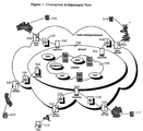
- FIG. 3 shows an architectural view of enterprise internet protocol telephony according to an embodiment of the present invention;
- FIG. 4 presents the components for a Public Switched Telephone Network (PSTN) initiated call according to the method and system of an embodiment of the present invention;
- FIG. 5 describes the call flow process of FIG. 4, according to an embodiment of the present invention;
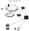
- FIG. 6 is an overview diagram of the components for internet initiated calls according to an embodiment of the present invention; and
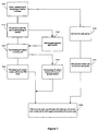
- FIG. 7 describes the call flow process of FIG. 6, according to an embodiment of the present invention.
-
- The present invention comprises a method and system for providing services and executing business transactions for customers using the internet or private data networks, rather than solely over regular current long distance networks. The internet is defined in this invention as any public data network. The internet serves, in this invention, as the medium over which long distance voice traffic is moved from the customer's premise to the corporate premise or call center for the purpose of executing business transactions and services; similarly, private data networks are usable wholly or partially for this purpose.
- The invention substantially reduces long distance telephone charges that are incurred by corporations in servicing toll free numbers. As a result, these corporations achieve low long distance communication rates, which likewise result in lower costs for customers. Another benefit of the present invention is that it provides the capability to allow businesses to offer international services identical to those currently offered within the United States, at about the same cost internationally as nationally. Provisioning of these services both nationally and internationally at greatly reduced rates provides tremendous cost savings opportunities for U.S. businesses and corporations because it provides the capability to put the world, financially and economically, into a single forum.
- Thus, an embodiment of the present invention allows customers in places such as China to access, for example, call centers worldwide pertaining to a corporation, regardless of the location of the corporation. For example, if the customer is in China, the customer can access a financial institution, such as Citibank, at a single call cost rate, whether the access location is Tokyo, Japan, Sydney, Australia, or Austin of Texas. One aspect of this architecture is that, once implemented, services, such as financial services may be provided and used without regard to the cost of long distance charges, which in many cases in the prior art was prohibitive for businesses.
- FIG. 1 shows an example of a prior art network for voice transport that has traditionally resulted in high rates for long distance telephone charges to businesses. Typically, a customer would contact a business, such as a financial institution, by dialing a toll free number such as an 800, 888, or 887 number, or some other toll free numbering scheme designated by the institution; the 800 number is used here as an example. The customer is subsequently connected, for example, to a call center maintained by the financial institution as follows.
- The number the customer dials is first received and analyzed by a
Class 5 local switch at one of the manycentral offices 10 belonging to a local exchange carrier (LEC), which is typically a local telephone company. The number includes 1-800 and additional numbers. Once the 800 portion of the number is received, thelocal switch 10 determines that the number is a special kind of number, and additional processing is needed. Usually, thelocal switch 10 further determines the carrier identification (carrier I.D.). Thus, for example, the local switch identifies MCI Worldcom by the next three numbers after the 800 number, which are 999, AT&T by the numbers 542, etc. - From the carrier ID number, the
local switch 10 first determines the carrier that is servicing the 800 number by accessing a local switch database. The 800-number carrier is typically an Interexchange Carrier (IXC or IEC), which is typically a long distance carrier, such as AT&T, MCI Worldcom, or Sprint; however, local telephone companies also provide limited 800 service. Associated with the IXC are trunk groups, which can include coaxial cables or other telecommunications connections, connected to thelocal switch 10. The call is then transferred to atoll office 20, typically aClass 4 switch at atandem office 20. Once the call is received by thetoll switch 20, the toll switch receives the 800 number from the local office. Thetoll switch 20 also recognizes that the 800 number is atypical, and the toll switch refers to an adjunct database for information regarding the IXC identified by the local switch database. - The
toll switch 20 uses the 800 number as a key, and the adjunct database provides an actual destination number (described further below), so that the database basically provides the switch with indication of whether the 800 number that was dialed by the customer should be dialed and the call transmitted to a destination number, which has the following form: NPA-NXX-XXXX, assuming the North American Numbering Plan (NANP) is followed. NPA is the area code, NXX is basically an exchange number, and XXXX is the four-digit line number. The destination number provides the number of the destination location and number where that call should terminate, such as a call center private branch exchange (PBX). - The
toll switch 20 then switches the call to a similardestination toll switch 50, which can be located thousands of miles away, via IXCcentral offices central offices destination toll switch 50 then determines from the destination number which terminatinglocal switch 60 services the exchange indicated by the number, and thetoll switch 50 then sends the call to that local switch, which dials the destination. In this case, the destination is a call center maintained by the financial institution and designated with the exchange being called. The call is then connected, for example, to a call center PBX. - With the advent of 800 portability, customers no longer have to stay with a particular long distance carrier in order to retain their 800 numbers. Before, for example, a customer with a toll free number starting with 800-999 must have MCI Worldcom as the long distance carrier for the number. Now, with the creation of an 800 data base service as required by the Federal Communication Commission (FCC), customers own their 800 numbers, and they are able to pick their long distance carriers, the same way that individuals pick carriers for home phone numbers. Thus, businesses can each have its own 800 number(s), and these businesses can have their calls transported by, for example, MCI today and by AT&T tomorrow, and by Sprint the next day.
- FIG. 2 provides a telephone network view as an example of the current state of the art in network architectures supporting commercial systems, such as call centers, and providing 800 portability. The present network architecture operates as follows. A communication request, such as a phone call, is initiated at an input terminal, such as a telephone. The call is then connected to the network via a network interface device (NID) 110 or a local loop 120, which are parts of the
local network 100 of a LEC. Depending on its nature, the call from theNID 110 can either be routed to an interoffice facility within theLEC network 100 or directly to a switchedaccess 210 within thenetwork 200 of an IEC. The call from the local loop 120 is also routed to an interoffice-facility of theLEC network 100. The interoffice facility comprises alocal switch 130 and atandem switch 140. Thelocal switch 130 functions similarly to theClass 5 local switch mentioned earlier and provides direct connections with the local loop 120 and theNID 110. Thetandem switch 140 functions similarly to theClass 4 switch mentioned earlier and acts as an intermediate switch connecting one trunk to another and to the switchedaccess 210, which is another intermediate switch belonging to theIEC network 200. Thelocal switch 130 then connects the call from either theNID 110 or the local loop 120 to a trunk group to be switched by thetandem switch 140. - When needed, the interoffice facility, which includes the
local switch 130 and thetandem switch 140, requests and receives information and/or instructions to route the call from an operator services center (OSC) 150 and a signal transfer point (STP) 160 within theLEC 100. TheOSC 150 handles a variety of telephone services which need the assistance of an operator, such as collect calls, calling card calls, third-party billing calls, and person-to-person calls. TheSTP 160 is a packet switch within a network that converts dialed digits to data messages. It requests and receives call routing information and instructions from an appropriate database indicated by the service control point (SCP) 170. The database supplies the translation and routing data needed to deliver advanced network services, such as toll free number, calling card, collect and third-party billing telephone calls, and it is made available to thelocal SCP 170 by a national service management system (SMS) 180, which also updates information on callers, subscribers, and services for billing and administrative purposes. TheSTP 160 then channels the received information and instructions to thelocal switch 130, thetandem switch 140, thelocal OSC 150, and/or the STP 260 andOSC 250 of theIEC 200 to facilitate routing of the call. Additional information and instructions may also be available from the SCP 270 of theIEC 200. The database of the SCP 270 is also made possible by the national SMS 180 (not shown connected). - The call is now transferred from the switched
access 210 of theIEC 200 that is associated with theoriginating LEC 100 to the switchedaccess 310 of theIEC 300 that is associated with thedestination LEC 400 via digital signal, level zero (DS0) communication protocol. It should be noted that theIEC 300 and theIEC 400 may be parts of the same telecommunication company or of different ones. Concurrently, the data needed to route the call and deliver advanced network services associated with the call are also transferred from the originatingIEC 200 to thedestination IEC 300 via signaling system 7 (SS7) networking protocol. Thedestination IEC 300 andLEC 400 function similarly to the originatingIEC 200 andLEC 100, but in a reverse manner, to route the call to theappropriate destination NID 410 or local loop 420. - When a customer accesses a business, such as a financial institution, at one of its call centers being managed by the network structure of FIG. 2, the customer begins, for example, by dialing a toll free number provided by the financial institution. The toll free number can be an 800 number, an 888 number, an 887 number, or some other toll free numbering scheme; the 800 number is used here as an example. The number the customer dials is sent from the local loop 120 or the NID 120, and received and analyzed by the
local switch 130. The number includes 1-800 and additional numbers. Once the 800 portion of the number is received, thelocal switch 130 determines that the number is a special kind of number, and additional processing is needed. It then processes the call according to routing instructions it receives from anappropriate SCP 170 via theSTP 160. The routing instructions include the identification of the carrier of the 800 number, which can be an LEC or an IEC, and the 10-digit destination number mentioned earlier. Thus, if the 800 number is managed by either theIEC 300 orIEC 400, additional routing instructions will be given by therespective STPs 260, 360 andSCPs 270, 370. The routing instructions enable the call to be directed to adestination tandem switch 440 servicing the destination number. Thetandem switch 440 then determines from the destination number which terminating local switch services the exchange indicated in the destination number, and thetandem switch 440 then sends the call to the appropriatelocal switch 430, which dials the destination at the appropriatelocal loop 410 or local loop 420 corresponding to, for example, a call center PBX. The call is then connected. - The networking processes shown in FIGs. 1 and 2 are entirely regulated by the Federal Communications Commission (FCC). Regulations include strict quality requirements, strict post dialing delay requirements, and charge levy restrictions, particularly relating to the distance covered by the call. These figures are intended to be representatives only, in order to explain typical existing configurations, and also in order to show the high level of complexity into which existing networks are typically bootstrapped, which is a fundamental contributor to the current high rates for calls and high cost of voice transport. For example, for each toll free call received by a business, the business has to pay both the local connection to an LEC and a long distance charge to an IEC, not to mention the service charges from the carrier of the toll free number.
- An embodiment of the present invention involves a different approach to long distance calling and other voice communications. As shown in the architectural view presented in FIG. 3, in an embodiment of the present invention, the call procedure differs from the prior art as follows. After a toll free number, such as an 800 number, is dialed by a customer from any one of the illustrated
locations local office 520 corresponding to that originating location. Thelocal office 520 is typically aClass 5 local switch, and it determines the carrier I.D. by comparison to a database for carrier I.D on the internet protocol (IP)access server 530 associated with each of thelocal offices 520. In an embodiment of the present invention, this carrier I.D. is not the normal carrier I.D., but a special carrier I.D. designated for use with the present invention. This new carrier I.D. has its own outgoing trunk groups from thelocal switch 520, which terminate at anIP router switch 540. In contrast to typical telephone switches of the prior art, theIP router switch 540 used by the present invention at its receiving end is connected to trunk groups for calls connected to thelocal office 520 and other offices. Thus, this end of theIP router switch 540 functions similarly to a toll switch or a tandem switch of the prior art, as far as protocol is concerned. At its other end, theIP router switch 540 sends the call across a packet network instead of a traditional circuit network. This allows theIP router switch 540 to send the call as a data stream usable over, for example, theinternet 700 or aprivate data network 750. Thus, for example, an embodiment of the present invention uses anIP router switch 540 that is an Internet Protocol Exchange (IPX) machine router switch having an IP address known to the internet like any other server. ThisIP router switch 540 thus receives and sends data over the network. - Thus, according to an embodiment of the present invention, a call is received, the call information is inputted into a database or an
adjunct database 530, the call is mapped, the 800 number is mapped similarly to the way the switches of the prior art map numbers, but the database includes another field that maps the call to an IP address of theIP router switch 540 servicing that number. In an embodiment of the present invention, the voice data from the customer is converted in theIP router switch 540 into packet data, using a method that is known in the art. The packet data is thus transmitted as data streams, which may be communicated, for example, over the internet using a method that is a lot cheaper than the prior art and equally as fast. Thus, the present invention incorporates the use of information about the call that allows the system to determine that the call terminates, for example, in Los Angeles, but also that the call is addressed to the IP address of anIP router switch 540 located in Los Angeles. Once the information regarding the IP address is determined, the call is routed through, for example, theinternet 700. - Another advantage of the present invention is that it eliminates the need for an international numbering agreement and code because the present invention bypasses all of the current telecommunication regulations and allows use of international 800 numbering. The fundamental reason for this is that the present invention functions as an international transport and relies upon a local connection to a national telecommunication company or post telephone and telegraph administration (PTT). Although the long distance/international carrier may still have to pay long distance (LD) charges to the local PTT, for instance, when the IP router switch is physically located at some long distance away from the caller's initiated calling point, the overall resulting cost can be at least an order of magnitude lower than what is currently paid for long-distance charges. The main other charges that the carrier is expected to charge as a fair cost per line may include the following: 1) administrative work such as billing; 2) cost of a connection, such as a T1 or T3 line, from the local office to the toll offices; and 3) cost of equipment or cost of lease.
- In the future, customers are expected to continue to utilize present network capabilities, and with the continued evolution of products in the market, including the present invention, much of the network capabilities continue to be available. The following list encompasses some of the more critical capabilities and services that are incorporable into a PSTN/IP network solution in accordance with an embodiment of the present invention: 1) very low per port costs (capital); 2) enhanced services such as multiple call handling, hold, retrieve, and selective drop; operator assistance; routing rules for inbound calls; Dual Tone Multiple Frequency (DTMF) generation for interaction with IVR and voice mail systems; corporate/personal directory lookup and dial; and speed dials and voice mail shortcuts; 3) reliable local and long distance voice and data service over IP networks; 4) managed bandwidth and quality of service mechanisms based on type of service, source/destination, protocol, and originating/terminating location; 5) central office switch routing for IP access (essentially a network element); 6) availability of billing/directory services; 7) transparent access to caller (no special equipment required); and 8) utilization of a corporate "intranet" for added security and cost savings.
- In an embodiment of the present invention, for call center applications using the network architectural framework of FIG. 3, calls initiated through the Public Switched Telephone Network (PSTN) continue to be handled by the Network Integrated Voice Response system (NIVR) in the same manner as with telephone calls over existing call networks, as described, for example, in the following. The NIVR is includes multiple IVRs at different locations connected together by a network that can route incoming calls to any one of the IVRs. The NIVR first receives a request via the present mechanisms as they are proposed and implemented in accordance with the network architecture in FIG. 3. The call flow changes are reflected in the NIVR to PSTN handoff. In this case, the NIVR returns the respective PSTN toll free number as it presently does. The call is then terminated to the IP access/IP switch, which performs address translation and routes the call to the appropriate terminating IP access/IP switch and onto the terminating call center.
- FIGs. 4 and 5 illustrate the call flow of a PSTN initiated call over the network shown in FIG. 3, as described above, in accordance with an embodiment of the present invention. The call flow uses and interacts with applications and existing systems of a business, such as a financial institution, as follows. In S1, the
customer 810 begins by dialing a toll free number given by the financial institution. In S2, a local switch (not shown) performs digit analysis of the number and routes the call to atelephone network 828, such as that of an IXC (e.g., MCI), chosen by the financial institution as the carrier of the toll free number. In S3, the call enters the telephone network through atoll switch 820, which then routes the call through the IP backbone intra/inter network 832 (either the financial institution's private data network or the internet is usable for transport) using anIP switch system 826 as a network router. A PSTN-to-IP, i.e., voice-to-IP, conversion is first performed on the call by anIP access switch 827 upon its entrance into the IP network 832. In S4, the call is then routed by theIP switch system 826 to a terminating IP access switch, also represented byblock 827, where the call is re-converted from IP back to PSTN. In S5, the reconverted call is routed from the IP access switch to a terminatingtoll switch 830. Subsequently in S6, the terminatingtoll switch 830 routes the call to a terminatingNIVR 836 of the financial institution. Since the call traverses both the PSTN and IP network in an embodiment of the present invention, the caller's initiated terminal 810 must have DTMF tone, i.e., touch tone, capability. - Consequently, the
NIVR 836 receives and begins processing the call. TheNIVR 836 manages services such as multiple call handling, hold, retrieve, routing rules for inbound calls, etc. In S7, theNIVR 836 informs a Voice Enhanced Service Processor (VESP) 846 of the call request as follows. TheNIVR 836 processes the call and sends customer or call contact information to a comprehensive central database, e.g., a Global Customer Information Facility (GCIF) 840, for validation. TheGCIF 840 is a system that accesses customer account information. In S7, theGCIF 840 sends call contact information to a Voice Operated Exchanger (VOX) server on theVESP 846. The call contact information include, for example, account number of the caller, originating Automatic Number Identification (ANI) (i.e., caller ID), place of exit from the NIVR, and/or call-ID provided by the NIVR (pseudo-ANI). The originating ANI is, for example, the 10-digit telephone number assigned to the input terminal at which the caller initiates the call, assuming again that the NANP is being used. The place of exit from the NIVR information is needed to route the customer account information to a proper call center. The NIVR determination of a proper call center depends on a number of parameters set out by the financial institution; for example, the least busy call center in the overall network of the institution will the get the call. The pseudo-ANI identifies the destination call center to which the call is routed. It is an internal ANI, recognized only by the financial institution network, that has been convened from the original ANI by theNIVR 836. This is done, for example, by having theNIVR 836 replacing the last 5 digits of the original ANI with 5 pseudo ANI digits. - The VOX server is typically a software residing on the
VESP 846 that provides voice activation of theVESP 846 to coordinate and track incoming call information. A record of such information is kept for administrative purposes, such as when the call center wants to gather statistical information about the number of incoming calls, duration of the calls, etc.; or in case the call gets disconnected, the customer service agent (CSA) at the call center can call back the customer. After receiving and processing the call contact information from theGCIF 840, theVESP 846 forwards the information to a Voice Data Unit (VDU) server (not show). The VDU server creates a VDU record containing, for example, VDU-ID, Pseudo-ANI, and Customer Identification Number (CIN) (from GCIF). Together, the VOX server, the VESP, and the VDU server form a Computer Telecity Interface (CTI) that enables customer information relating to the calling customer to be downloaded to the proper call center and displayed on the desktop computer of the proper CSA handling the call from the customer. This so called screen pop at theCSA desktop 850 presents the CSA with information such as the customer's name and account number, and other information as desired by the financial institution, so that the CSA can better serve the customer. - In S8, while the
NIVR 836 processes the call to provide the screen pop as described above, it also converts the toll-free number of the call into a regular number and dials the latter to connect the call to a call center via thetelephone network 828. In S9, the call arrives back at thetoll switch 830 and alternately can trigger an adjunct dip to another level of call routing, such as the Network Interactive Call Response (NICR) 824, for future upgrades. The NICR, for example, provides more capability in terms of holding, redirecting, and rerouting calls in various situations. The route is then returned from the NICR, or if there is not another level of call routing, the route remains at thetoll switch 830, and the call is routed by thetelephone network 828 to a terminating local PBX Automatic Call Distributor (ACD) 860, which acts as the call center PBX. ThePBX ACD 860 is a switch located at each call center of the financial institution, and it takes incoming calls and route them to available CSAs. Finally in S10, thePBX ACD 860 receives the call, matches the call record with the VESP information, and routes the call to theparticular CSA 870 that is presented with thescreen pop 850 of the customer information of the caller, as mentioned earlier. The call is now connected. Voice transport from theCSA 870 back to thecaller 810 during the call is done in reverse through the same route as described above, i.e., through thePBX ACD 860 to theNIVR 836 and thetoll switch 830, through the IP network 832 with PSTN-to-IP-to-PSTN conversions, to thetoll switch 820, and back to thecaller 810. - In another embodiment of the present invention, the customer can initiate the call directly through the internet rather than via the PSTN as described above. Figs. 6 and 7 illustrate the call flow of an internet initiated call over the network shown in FIG. 3, in accordance to an embodiment of the present invention. In S100, the customer begins by accessing a computer and
internet telephone 910 and calling to an IP address provided by the financial institution. PSTN-to-IP conversion of the call is typically done at thecustomer location 910. In S101, anIP switch 920 routes the call, via an IP backbone intra/inter network (again, either the financial institution's private data network or the public internet is usable for transport), to a terminating IP switch 930. In S102, once again, the call may also trigger an adjunct dip to another level of call routing, such as theNICR 924, for future upgrades. In that case, the call is subsequently returned from theNICR 924 back to the terminating IP switch 930. In S103, the IP switch 930 receives the call and performs the IP-to-voice conversion as requested. In S104, it routes the call to thelocal PBX ACD 960 maintained by the banking institution. Alternatively in S105, the IP switch 930 can route the call to anIP access switch 927 for a different connection protocol with thePBX ACD 960 using, for example, Integrated Services Digital Network Primary Rate Interface (ISDN PRI), which is a well known communication protocol in the art. In this instance, either theIP access switch 927 or the IP switch 930 can perform the IP-to-voice conversion as requested. - In S106, the internet initiated call from the
computer 910 is also sent to an IPaccess web server 936 maintained by the financial institution, based on the accessed internet address. In S107, theserver 936 routes the call to aninternet call center 940 for processing. Thecall center 940 functions similarly to the CTI of FIG. 4 in that it coordinates with thePBX ACD 960 to download customer information relating to the particular calling customer to the proper call center and display such information on thedesktop computer 950 of aCSA 970. This screen pop at the CSA'sdesktop 950 presents theCSA 970 with information such as the customer's name and account number, and other information as desired by the financial institution, so that the CSA can better serve the customer. - Finally in S108, the
PBX ACD 960 receives the call from either theIP access switch 927 or the IP switch 930, coordinates with theinternet call center 940, and routes the call to theparticular CSA 970 that is presented with the screen pop of customer information as mentioned earlier. The call is now connected. Voice transport from theCSA 970 back to thecaller 910 during the call is done in reverse through the same route as described above, i.e., through thePBX ACD 960 to theIP access switch 927 or IP switch 930 with PSTN-to-IP conversion, through theIP network 928 to theIP switch 920, and with IP-to-PSTN conversion back to thecaller 910. - PSTN initiated calls and internet initiated calls provide substantial savings to businesses. Long distance charges relating to toll free numbers maintained by the businesses for customer services are practically eliminated. Furthermore, with internet initiated calls, local phone charges are also eliminated. The result is lower overheads and substantial savings to the businesses, which can be passed on to the consumers.
- Embodiments of the present invention have now been described in fulfillment of the above objects. It will be appreciated that these examples are merely illustrative of the invention. Many variations and modifications will be apparent to those skilled in the art.
Claims (41)
- A method for providing voice transport over an internet protocol (IP) network between a host and an access location, comprising:receiving a voice call from a caller at the access location;routing the call to the IP network;routing the call from the IP network to a local switching network of the host; androuting the call from the local switching network to a destination maintained by the host.
- The method of claim 1, wherein the destination is a call center of the host.
- The method of claim 1, wherein the host is a financial institution.
- The method of claim 1, wherein routing the call from the local switch network to the destination comprises routing the call to one of a plurality of customer service agents of the host located at the destination.
- The method of claim 1, wherein the local switch network comprises a private branch exchange (PBX) maintained by the host.
- The method of claim 1, wherein routing the call to the IP network comprises:routing the call to a first IP switch of the IP network;converting the call from voice format to IP format;routing the call in IP format from the first IP switch to a second IP switch of the IP network; andre-converting the IP-formatted call received at the second IP switch to voice format.
- The method of claim 1, further comprising routing the call from the access location to a server system maintained by the host.
- The method of claim 7, further comprising:the server system accessing information about the call upon receipt of the call; anddownloading the accessed information to the destination maintained by the host.
- The method of claim 1, further comprising routing the call from the access location to a server system maintained by the host.
- The method of claim 9, further comprising:the server system accessing information about the call upon receipt of the call;transferring the accessed information to a call processing center of the host; andthe call processing center coordinating with the PBX to download the accessed information to the destination in concurrence with routing the call from the local switching network to the destination.
- The method of claim 10, wherein the destination is staffed by an agent of the host.
- The method of claim 1, wherein routing the call to the IP network comprises:routing the call to a first IP switch of the IP network;routing the call from the first IP switch to a separate level of call routing; andreturning the call from the separate level of call routing to a second IP switch of the IP network.
- The method of claim 12, wherein routing the call from the IP network to the local switching network comprises routing the call from the second IP switch of the IP network to the local switching network.
- The method of claim 1, wherein routing the call to the IP network comprises:routing the call from the access location to a telephone network; androuting the call from the telephone network to the IP network.
- The method of claim 14, wherein routing the call to the telephone network comprises:routing the call from the access location to a first toll switch of the telephone network.
- The method of claim 15, wherein routing the call from the telephone network to the IP network comprises:routing the call from the first toll switch of the telephone network to a first IP switch of the IP network;sending the call through the IP network from the first IP switch of the IP network to a second IP switch of the IP network;routing the call from the second IP switch of the IP network to a second toll switch of the telephone network;routing the call from the second toll switch of the telephone network to a call response system;accessing information of the caller from the call response system;validating the caller information; andsending the validated caller information to the destination maintained by the host.
- The method of claim 16, wherein the host is a financial institution.
- The method of claim 17, wherein sending the validated caller information to the destination comprises:sending the validated caller information to a computer staffed by an agent of the financial institution.
- The method of claim 17, wherein routing the call from the local switching network to the destination comprises routing the call from the local switching network to a voice terminal staffed by the agent of the financial institution.
- The method of claim 16, wherein routing the call from the telephone network to the IP network further comprises:routing the call from the call response system to the IP network.
- The method of claim 16, wherein routing the call from the telephone network to the IP network further comprises:routing the call from the call response system back to the second toll switch of the telephone network;sending the call from the second toll switch to another call response system;returning the sent call from the another call response system; androuting the returned call to the IP network.
- A method for providing voice-to-voice communication over an internet protocol (IP) network between a host and an access location, comprising:receiving a telephone call from a caller at the access location;routing the call to a telephone network;providing a first transferring of the call from the telephone network to the IP network;re-routing the call from the IP network back to the telephone network;providing a second transferring of the call from the telephone network to a network integrated voice response system (NIVR);accessing information about the caller from the NIVR based on the call;downloading the accessed information to a call center maintained by the host;re-routing the call from the NIVR to the IP network; andtransferring the call from the IP network to the call center maintained by the host.
- The method of claim 22, wherein the host is a financial institution.
- The method of claim 22, wherein the telephone network is a public switched telephone network (PSTN).
- The method of claim 22, wherein the IP network is an internet.
- The method of claim 22, wherein the IP network is a private data network maintained by the host.
- The method of claim 22, wherein:transferring the call from the IP network to the call center comprises transferring the call to a voice transport terminal at the call center; anddownloading the accessed information to the call center comprises downloading the accessed information to a computer at the call center associated with the voice transport terminal.
- The method of claim 27, wherein the voice transport terminal is a telephone staffed by a customer service agent (CSA) of the host.
- The method of claim 28, wherein the computer at the call center is serviced by the same CSA of the host.
- The method of claim 29, wherein the CSA is able to concurrently answer the call and view the accessed information on the computer.
- A system for providing voice-to-voice communication with an access location over an internet protocol (IP) network, comprising:a first network system coupled to the IP network;a telephone network coupled to the IP network and the host system;an access location coupled to the telephone network; anda second network system coupled to the telephone network;
wherein the access location is capable of voice-to-voice communication with a host via a coordination between the telephone network and the IP network. - The system of claim 31, wherein the voice-to-voice communication between the access location and the host comprises:a telephone call sent from the access location to a telephone number provided by the host.
- The system of claim 32, wherein the telephone network comprises:a first toll switch for routing the telephone call through the telephone network; anda second toll switch for routing the telephone call from the telephone network to the second network system of the host.
- The system of claim 33, wherein the IP network comprises:an IP switch system for receiving and sending the telephone call to the second toll switch of the telephone network; anda terminating IP access switch associated with the first network system.
- The system of claim 34, wherein the IP switch system comprises:a first IP switch for receiving the telephone call from the first toll switch via the telephone network and converting the telephone call from a voice format to an IP format; anda second IP switch associated with the second network system for receiving the IP format of the telephone call and re-converting the IP format back to the voice format.
- The system of claim 34, wherein the IP access switch system comprises:a first IP access switch for receiving the telephone call from the first toll switch of the telephone network, converting the telephone call from voice format to IP format, and routing the IP-formatted call through the IP network; anda second IP access switch for receiving the IP-formatted call from the first IP access switch via the IP network, re-converting the IP format of the telephone call back to voice format, and sending the re-converted telephone call to the second toll switch of the telephone network.
- The system of claim 33, wherein the second network system comprises:a voice response system for accessing information about the telephone call and dialing the telephone number upon receipt of the telephone call from the second toll switch system of the telephone network;a database for receiving the accessed information from the voice response system and validating the accessed information; anda processor for receiving the validated information and, in conjunction with the database, downloading the validated information to a computer staffed by an agent of the host.
- The system of claim 37, wherein the processor is a voice enhanced service processor (VESP).
- The system of claim 37, wherein the database is a global customer information facility (GCIF).
- The system of claim 37, wherein the voice response system is a network integrated voice response system (NIVR).
- The system of claim 33, wherein the first network system comprises:a private branch exchange (PBX) maintained by the host and coupled to the IP network for receiving the telephone call and routing the telephone call to an agent of the host.
Applications Claiming Priority (2)
| Application Number | Priority Date | Filing Date | Title |
|---|---|---|---|
| US10136898P | 1998-09-22 | 1998-09-22 | |
| US101368P | 1998-09-22 |
Publications (2)
| Publication Number | Publication Date |
|---|---|
| EP0989723A2 true EP0989723A2 (en) | 2000-03-29 |
| EP0989723A3 EP0989723A3 (en) | 2003-05-28 |
Family
ID=22284293
Family Applications (1)
| Application Number | Title | Priority Date | Filing Date |
|---|---|---|---|
| EP99203086A Withdrawn EP0989723A3 (en) | 1998-09-22 | 1999-09-21 | Method and system for enterprise internet protocol telephony |
Country Status (2)
| Country | Link |
|---|---|
| EP (1) | EP0989723A3 (en) |
| SG (1) | SG99288A1 (en) |
Cited By (1)
| Publication number | Priority date | Publication date | Assignee | Title |
|---|---|---|---|---|
| EP1109389A1 (en) * | 1999-12-17 | 2001-06-20 | Siemens Aktiengesellschaft | Signaling and routing of calls to a call-center via IP network |
Citations (3)
| Publication number | Priority date | Publication date | Assignee | Title |
|---|---|---|---|---|
| WO1997016916A1 (en) * | 1995-11-01 | 1997-05-09 | Telecom Internet Ltd. | Method and apparatus for implementing a computer network/internet telephone system |
| WO1997028635A1 (en) * | 1996-02-02 | 1997-08-07 | Genesys Telecommunications Laboratories | Apparatus and methods for coordinating telephone and data communications |
| WO1998037665A1 (en) * | 1997-02-02 | 1998-08-27 | Fonefriend Systems, Inc. | Internet switch box, system and method for internet telephony |
Family Cites Families (3)
| Publication number | Priority date | Publication date | Assignee | Title |
|---|---|---|---|---|
| JP3777638B2 (en) * | 1995-12-18 | 2006-05-24 | ソニー株式会社 | Call system terminal device and call method |
| WO1997033412A1 (en) * | 1996-03-06 | 1997-09-12 | Bear Creek Technologies, Inc. | System for interconnecting standard telephony communications equipment to internet protocol networks |
| US5790548A (en) * | 1996-04-18 | 1998-08-04 | Bell Atlantic Network Services, Inc. | Universal access multimedia data network |
-
1999
- 1999-09-21 EP EP99203086A patent/EP0989723A3/en not_active Withdrawn
- 1999-09-21 SG SG9904677A patent/SG99288A1/en unknown
Patent Citations (3)
| Publication number | Priority date | Publication date | Assignee | Title |
|---|---|---|---|---|
| WO1997016916A1 (en) * | 1995-11-01 | 1997-05-09 | Telecom Internet Ltd. | Method and apparatus for implementing a computer network/internet telephone system |
| WO1997028635A1 (en) * | 1996-02-02 | 1997-08-07 | Genesys Telecommunications Laboratories | Apparatus and methods for coordinating telephone and data communications |
| WO1998037665A1 (en) * | 1997-02-02 | 1998-08-27 | Fonefriend Systems, Inc. | Internet switch box, system and method for internet telephony |
Non-Patent Citations (1)
| Title |
|---|
| KAUFMAN H: "CALL CENTERS IN CYBERSPACE" COMMUNICATIONS NEWS, XX, XX, vol. 34, no. 7, 1 July 1997 (1997-07-01), pages 20-21, XP002054723 * |
Cited By (1)
| Publication number | Priority date | Publication date | Assignee | Title |
|---|---|---|---|---|
| EP1109389A1 (en) * | 1999-12-17 | 2001-06-20 | Siemens Aktiengesellschaft | Signaling and routing of calls to a call-center via IP network |
Also Published As
| Publication number | Publication date |
|---|---|
| SG99288A1 (en) | 2003-10-27 |
| EP0989723A3 (en) | 2003-05-28 |
Similar Documents
| Publication | Publication Date | Title |
|---|---|---|
| US5917899A (en) | Method of connecting a plurality of virtual networks | |
| US5163087A (en) | Delivery of customer data base key using automatic number identification | |
| US6865266B1 (en) | Methods and apparatus for transferring from a PSTN to a VOIP telephone network | |
| US8982876B2 (en) | Method and system for customer selected direct dialed voice-over-internet protocol (VOIP) | |
| US6647108B1 (en) | Internet call manager | |
| US5499289A (en) | Systems, methods and articles of manufacture for performing distributed telecommunications | |
| US7447304B2 (en) | System and method for routing both toll-free and caller-paid telephone calls to call service centers | |
| US6947540B2 (en) | Method and network for providing access to an information network | |
| MXPA96004538A (en) | Method for obtaining billing validation directory account differences from basis of line identification data in a detelecommunication network | |
| US6327358B1 (en) | System and method for rerouting data calls to internet service provider via lowest access point in a telephone network | |
| US7277421B1 (en) | Telephone call processing using SIP and/or ENUM | |
| US7929674B1 (en) | Method and system for providing billing capability for a service node in an advanced intelligent network environment | |
| US7042999B2 (en) | Method and system for providing direct routing of local number portability (LNP) calls to alternate terminations | |
| US20080014950A1 (en) | Methods of routing interlata network traffic | |
| US20030156697A1 (en) | System and method to establish an on-demand expanded conference call for participants in an active two-party or three-way call | |
| US6671361B2 (en) | Telecommunications system and method relating to telecommunications services with number translation | |
| US6954455B1 (en) | Technique for providing intelligent features for calls in a communications network independent of network architecture | |
| US5987111A (en) | Method of aggregating a plurality of network traffic | |
| EP0924919A2 (en) | System and method for centrex translation | |
| US20060246951A1 (en) | Wireless intelligent network custom call routing for integrating enterprise networks with mobility networks | |
| US5905791A (en) | Method and apparatus for providing combined communication services including local service and toll service | |
| EP0989723A2 (en) | Method and system for enterprise internet protocol telephony | |
| US6813348B1 (en) | Method and system of call origination using a service circuit node in an advanced intelligent network | |
| AU9707101A (en) | Method and system for enterprise internet protocol telephony | |
| AU5008099A (en) | Method and system for enterprise internet protocol telephony |
Legal Events
| Date | Code | Title | Description |
|---|---|---|---|
| PUAI | Public reference made under article 153(3) epc to a published international application that has entered the european phase |
Free format text: ORIGINAL CODE: 0009012 |
|
| AK | Designated contracting states |
Kind code of ref document: A2 Designated state(s): AT BE CH CY DE DK ES FI FR GB GR IE IT LI LU MC NL PT SE |
|
| AX | Request for extension of the european patent |
Free format text: AL;LT;LV;MK;RO;SI |
|
| PUAL | Search report despatched |
Free format text: ORIGINAL CODE: 0009013 |
|
| AK | Designated contracting states |
Designated state(s): AT BE CH CY DE DK ES FI FR GB GR IE IT LI LU MC NL PT SE |
|
| AX | Request for extension of the european patent |
Extension state: AL LT LV MK RO SI |
|
| RIC1 | Information provided on ipc code assigned before grant |
Ipc: 7H 04M 3/523 B Ipc: 7H 04M 3/493 B Ipc: 7H 04M 7/00 A |
|
| AKX | Designation fees paid | ||
| REG | Reference to a national code |
Ref country code: DE Ref legal event code: 8566 |
|
| STAA | Information on the status of an ep patent application or granted ep patent |
Free format text: STATUS: THE APPLICATION IS DEEMED TO BE WITHDRAWN |
|
| 18D | Application deemed to be withdrawn |
Effective date: 20031201 |
|
| REG | Reference to a national code |
Ref country code: HK Ref legal event code: WD Ref document number: 1028310 Country of ref document: HK |