EP0989655A2 - Electric motor linear drive - Google Patents
Electric motor linear drive Download PDFInfo
- Publication number
- EP0989655A2 EP0989655A2 EP99117790A EP99117790A EP0989655A2 EP 0989655 A2 EP0989655 A2 EP 0989655A2 EP 99117790 A EP99117790 A EP 99117790A EP 99117790 A EP99117790 A EP 99117790A EP 0989655 A2 EP0989655 A2 EP 0989655A2
- Authority
- EP
- European Patent Office
- Prior art keywords
- worm
- linear drive
- drive according
- electromotive linear
- rotation
- Prior art date
- Legal status (The legal status is an assumption and is not a legal conclusion. Google has not performed a legal analysis and makes no representation as to the accuracy of the status listed.)
- Ceased
Links
Images

Classifications
-
- A—HUMAN NECESSITIES
- A47—FURNITURE; DOMESTIC ARTICLES OR APPLIANCES; COFFEE MILLS; SPICE MILLS; SUCTION CLEANERS IN GENERAL
- A47C—CHAIRS; SOFAS; BEDS
- A47C20/00—Head -, foot -, or like rests for beds, sofas or the like
- A47C20/04—Head -, foot -, or like rests for beds, sofas or the like with adjustable inclination
- A47C20/041—Head -, foot -, or like rests for beds, sofas or the like with adjustable inclination by electric motors
-
- F—MECHANICAL ENGINEERING; LIGHTING; HEATING; WEAPONS; BLASTING
- F16—ENGINEERING ELEMENTS AND UNITS; GENERAL MEASURES FOR PRODUCING AND MAINTAINING EFFECTIVE FUNCTIONING OF MACHINES OR INSTALLATIONS; THERMAL INSULATION IN GENERAL
- F16H—GEARING
- F16H1/00—Toothed gearings for conveying rotary motion
- F16H1/02—Toothed gearings for conveying rotary motion without gears having orbital motion
- F16H1/20—Toothed gearings for conveying rotary motion without gears having orbital motion involving more than two intermeshing members
- F16H1/22—Toothed gearings for conveying rotary motion without gears having orbital motion involving more than two intermeshing members with a plurality of driving or driven shafts; with arrangements for dividing torque between two or more intermediate shafts
- F16H1/222—Toothed gearings for conveying rotary motion without gears having orbital motion involving more than two intermeshing members with a plurality of driving or driven shafts; with arrangements for dividing torque between two or more intermediate shafts with non-parallel axes
- F16H1/225—Toothed gearings for conveying rotary motion without gears having orbital motion involving more than two intermeshing members with a plurality of driving or driven shafts; with arrangements for dividing torque between two or more intermediate shafts with non-parallel axes with two or more worm and worm-wheel gearings
-
- H—ELECTRICITY
- H02—GENERATION; CONVERSION OR DISTRIBUTION OF ELECTRIC POWER
- H02K—DYNAMO-ELECTRIC MACHINES
- H02K7/00—Arrangements for handling mechanical energy structurally associated with dynamo-electric machines, e.g. structural association with mechanical driving motors or auxiliary dynamo-electric machines
- H02K7/06—Means for converting reciprocating motion into rotary motion or vice versa
-
- H—ELECTRICITY
- H02—GENERATION; CONVERSION OR DISTRIBUTION OF ELECTRIC POWER
- H02K—DYNAMO-ELECTRIC MACHINES
- H02K7/00—Arrangements for handling mechanical energy structurally associated with dynamo-electric machines, e.g. structural association with mechanical driving motors or auxiliary dynamo-electric machines
- H02K7/10—Structural association with clutches, brakes, gears, pulleys or mechanical starters
- H02K7/116—Structural association with clutches, brakes, gears, pulleys or mechanical starters with gears
- H02K7/1163—Structural association with clutches, brakes, gears, pulleys or mechanical starters with gears where at least two gears have non-parallel axes without having orbital motion
- H02K7/1166—Structural association with clutches, brakes, gears, pulleys or mechanical starters with gears where at least two gears have non-parallel axes without having orbital motion comprising worm and worm-wheel
-
- Y—GENERAL TAGGING OF NEW TECHNOLOGICAL DEVELOPMENTS; GENERAL TAGGING OF CROSS-SECTIONAL TECHNOLOGIES SPANNING OVER SEVERAL SECTIONS OF THE IPC; TECHNICAL SUBJECTS COVERED BY FORMER USPC CROSS-REFERENCE ART COLLECTIONS [XRACs] AND DIGESTS
- Y10—TECHNICAL SUBJECTS COVERED BY FORMER USPC
- Y10T—TECHNICAL SUBJECTS COVERED BY FORMER US CLASSIFICATION
- Y10T74/00—Machine element or mechanism
- Y10T74/19—Gearing
- Y10T74/19219—Interchangeably locked
- Y10T74/19358—Laterally slidable gears
- Y10T74/19363—Rotary carriage
Definitions
- the present invention relates to an electromotive linear drive, in particular Furniture drive with a rotating drivable spindle on one of the output link forming and secured against rotation spindle nut, and with a worm gear, the worm on the motor pin of an electric motor is wedged.
- the linear actuator in question is available in many versions for the various uses known.
- the linear drive can be a simple drive be equipped with an electric motor and with a spindle and a spindle nut be, or also be a double drive with two electric motors and two Threaded spindles and two spindle nuts are equipped in a common Housing are arranged. They are also small drives with performance less than 1 KW.
- the worm of the worm drive is present made of steel, while the worm wheel meshing with it is made of plastic.
- the Motor pin of the worm placed on it under load, even if slightly, bends. This leads to the overlap between the snail and the The worm wheel decreases and the surface pressure increases. They are analogous Flanks of the worm wheel rubbed or crushed. This effect will still be there thereby favored that the motor pin of the Electric motor warmed.
- the present invention has for its object an electromotive To design the linear drive of the type described in more detail so that the through Forces and possibly heat caused wear of the screw in Engaging worm wheel is reduced or higher forces transmitted can be.
- the task is solved in that the worm of the worm gear with at least two axially parallel worm wheels in one to the axis of rotation of the worm symmetrical arrangement is engaged.
- the configuration of the worm drive according to the invention means that the forces occurring in engagement with the screw are largely eliminated. Thereby the motor journal, which has previously been subjected to bending, is only replaced by the one to be transmitted Torque loaded, but not by forces perpendicular to its axis of rotation.
- the invention can be implemented constructively if the Worm engages with two worm wheels, the axis of rotation of which is at an angle are offset from each other by 180 °.
- the worm wheels are then in one Level.
- the number of components is kept low in this embodiment.
- the electromotive linear drive is self-locking in one direction of rotation of the drive spindle. This can for example, be necessary if a component connected to the spindle nut is raised by means of the linear drive and the connected component in the respective Position should remain after switching off the electric motor.
- each worm gear is connected to a spur gear which is in engagement with the spur gear of the other worm gear.
- each worm gear with the associated spur gear as one piece Molded part is formed.
- the toothing of the spur gears can be straight or Be helical gears.
- a on each worm wheel and the associated spur gear protruding bearing pin is formed, on each of which a rolling bearing or a plain bearing is put on. The entire wheel arrangement is then stored in four places, so that a stable arrangement is created.
- the linear drive 10 is driven by a threaded spindle, either with a spur gear 15, 16 and possibly also with the associated worm wheel 13 or 14 is rotatably connected.
- the invention is not limited to the illustrated embodiment since it is essential is that the worm 12 has at least two worm gears in a symmetrical manner Arrangement are assigned to neutralize the bending force.
Landscapes
- Engineering & Computer Science (AREA)
- General Engineering & Computer Science (AREA)
- Power Engineering (AREA)
- Mechanical Engineering (AREA)
- Health & Medical Sciences (AREA)
- General Health & Medical Sciences (AREA)
- Nursing (AREA)
- Gear Transmission (AREA)
- Gears, Cams (AREA)
Abstract
Description
Die vorliegende Erfindung betrifft einen elektromotorischen Linearantrieb, insbesondere Möbelantrieb mit einer rotierend antreibbaren Spindel auf die eine das Abtriebsglied bildende und gegen Verdrehung gesicherte Spindelmutter aufgesetzt ist, und mit einem Schneckentrieb, dessen Schnecke auf den Motorzapfen eines Elektromotors aufgekeilt ist. Der in Frage kommende Linearantrieb ist in vielen Ausführungen für die verschiedensten Einsatzzwecke bekannt. Der Linearantrieb kann ein einfacher Antrieb sein, d.h., mit einem Elektromotor und mit einer Spindel und einer Spindelmutter ausgerüstet sein, oder auch ein Doppelantrieb sein, der mit zwei Elektromotoren und zwei Gewindespindeln und zwei Spindelmuttern ausgerüstet ist, die in einem gemeinsamen Gehäuse angeordnet sind. Es handelt sich außerdem um Kleinantriebe mit Leistungen unter 1 KW.The present invention relates to an electromotive linear drive, in particular Furniture drive with a rotating drivable spindle on one of the output link forming and secured against rotation spindle nut, and with a worm gear, the worm on the motor pin of an electric motor is wedged. The linear actuator in question is available in many versions for the various uses known. The linear drive can be a simple drive be equipped with an electric motor and with a spindle and a spindle nut be, or also be a double drive with two electric motors and two Threaded spindles and two spindle nuts are equipped in a common Housing are arranged. They are also small drives with performance less than 1 KW.
Bei den bisher bekannten Ausführungen besteht die Schnecke des Schneckentriebes aus Stahl, während das damit in Eingriff stehende Schneckenrad aus Kunststoff besteht. Bei diesen an sich bewährten Ausführungen hat sich herausgestellt, daß sich der Motorzapfen der darauf aufgesetzten Schnecke unter Belastung, wenn auch geringfügig, verbiegt. Dies führt dazu, daß die Überdeckung zwischen Schnecke und dem Schneckenrad abnimmt und die Flächenpressung zunimmt. Sinngemäß werden die Flanken des Schneckenrades abgerieben bzw. zerquetscht. Dieser Effekt wird noch dadurch begünstigt, daß sich im Betrieb des Linearantriebes der Motorzapfen des Elektromotors erwärmt.In the previously known designs, the worm of the worm drive is present made of steel, while the worm wheel meshing with it is made of plastic. In these proven designs it has been found that the Motor pin of the worm placed on it under load, even if slightly, bends. This leads to the overlap between the snail and the The worm wheel decreases and the surface pressure increases. They are analogous Flanks of the worm wheel rubbed or crushed. This effect will still be there thereby favored that the motor pin of the Electric motor warmed.
Der vorliegenden Erfindung liegt die Aufgabe zugrunde, einen elektromotorischen Linearantrieb der eingangs näher beschriebenen Art so zu gestalten, daß der durch Kräfte und gegebenenfalls Wärme hervorgerufene Verschleiß des mit der Schnecke in Eingriff stehenden Schneckenrades vermindert wird bzw. höhere Kräfte übertragen werden können.The present invention has for its object an electromotive To design the linear drive of the type described in more detail so that the through Forces and possibly heat caused wear of the screw in Engaging worm wheel is reduced or higher forces transmitted can be.
Die gestellte Aufgabe wird gelöst, in dem die Schnecke des Schneckentriebes mit wenigstens zwei achsparallelen Schneckenrädern in einer zur Drehachse der Schnecke symmetrischen Anordnung in Eingriff steht.The task is solved in that the worm of the worm gear with at least two axially parallel worm wheels in one to the axis of rotation of the worm symmetrical arrangement is engaged.
Durch die erfindungsgemäße Konfiguration des Schneckentriebes werden die durch die in Eingriff mit der Schnecke auftretenden Kräfte weitgehend aufgehoben. Dadurch wird der bislang auf Biegung beanspruchte Motorzapfen nur noch durch das zu übertragende Drehmoment belastet, nicht jedoch durch Kräfte senkrecht zu seiner Drehachse.The configuration of the worm drive according to the invention means that the forces occurring in engagement with the screw are largely eliminated. Thereby the motor journal, which has previously been subjected to bending, is only replaced by the one to be transmitted Torque loaded, but not by forces perpendicular to its axis of rotation.
In einfachster Ausführung läßt sich die Erfindung konstruktiv umsetzen, wenn die Schnecke mit zwei Schneckenrädern in Eingriff steht, deren Drehachse um einen Winkel von 180° Grad zueinander versetzt sind. Die Schneckenräder liegen dann in einer Ebene. Außerdem wird bei dieser Ausführung die Anzahlt der Bauteile gering gehalten. Je nach Einsatzzweck kann es erforderlich werden, daß der elektromotorische Linearantrieb in einer Drehrichtung der Antriebsspindel selbsthemmend ist. Dies kann beispielsweise notwendig sein, wenn ein an die Spindelmutter angeschlossenes Bauteil mittels des Linearantriebes angehoben wird und das angeschlossene Bauteil in der jeweiligen Stellung nach Abschalten des Elektromotors verbleiben soll. Um diese Forderung zu erfüllen, ist vorgesehen, daß jedes Schneckenrad mit einem Stirnrad verbunden ist, welches mit dem Stirnrad des anderen Schneckenrades in Eingriff steht. Durch diese Anordnung wird ein Doppelschneckenstirnradgetriebe geschaffen, welches selbsthemmend ist, da der Gesamtwirkungsgrad durch die beiden Stirnräder herabgesetzt wird. Die Teilkreise der beiden Stirnräder sind größer als die Außendurchmesser der Schneckenräder und berühren sich in der Ebene der Drehachse der Schnecke. Darüber hinaus wird durch eine derartige Gestaltung erreicht, daß sich das Gesamtdrehmoment, welches durch die Schnecke eingeleitet wird, auf zwei oder mehr Schneckenräder verteilt. Dadurch kann ein solches Getriebe ein deutlich größeres maximales Drehmoment übertragen als ein herkömmliches Schneckengetriebe. In the simplest version, the invention can be implemented constructively if the Worm engages with two worm wheels, the axis of rotation of which is at an angle are offset from each other by 180 °. The worm wheels are then in one Level. In addition, the number of components is kept low in this embodiment. Depending on the application, it may be necessary that the electromotive linear drive is self-locking in one direction of rotation of the drive spindle. This can for example, be necessary if a component connected to the spindle nut is raised by means of the linear drive and the connected component in the respective Position should remain after switching off the electric motor. To this demand to meet, it is provided that each worm gear is connected to a spur gear which is in engagement with the spur gear of the other worm gear. By this arrangement creates a twin worm gear, which is self-locking because the overall efficiency is reduced by the two spur gears becomes. The pitch circles of the two spur gears are larger than the outside diameter of the worm wheels and touch in the plane of the axis of rotation of the worm. About that is also achieved by such a design that the total torque, which is introduced by the snail to two or more Worm wheels distributed. As a result, such a transmission can have a significantly larger maximum Torque transmitted as a conventional worm gear.
Um die Montage zu vereinfachen und die Anzahl der Teile gering zu halten, ist es zweckmäßig, wenn jedes Schneckenrad mit dem zugehörigen Stirnrad als einstückiges Formteil ausgebildet ist. Die Verzahnungen der Stirnräder können Gerad- oder Schrägverzahnungen sein. Zur optimalen Lagerung der Schneckenräder und der Stirnräder ist vorgesehen, daß an jedem Schneckenrad und dem zugehörigen Stirnrad ein vorstehender Lagerzapfen angeformt ist, auf den jeweils ein Wälzlager oder ein Gleitlager aufgesetzt ist. Die gesamte Räderanordnung wird dann an vier Stellen gelagert, so daß eine in sich stabile Anordnung geschaffen ist.To simplify assembly and keep the number of parts low, it is useful if each worm gear with the associated spur gear as one piece Molded part is formed. The toothing of the spur gears can be straight or Be helical gears. For optimal storage of worm gears and spur gears it is provided that a on each worm wheel and the associated spur gear protruding bearing pin is formed, on each of which a rolling bearing or a plain bearing is put on. The entire wheel arrangement is then stored in four places, so that a stable arrangement is created.
Anhand der beiliegenden Zeichnungen wird die Erfindung noch näher erläutert.The invention is explained in more detail with reference to the accompanying drawings.
Es zeigen:
- Figur 1
- Den erfindungsgemäßen elektromotorischen Linearantrieb in einer Daraufsicht, rein schematisch und
- Figur 2
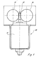
- den Linearantrieb nach der Figur 1 in einer Schnittdarstellung, quer zur
Längsachse der Schnecke. Der in der Figur 1 dargestellte
elektromotorische Linearantrieb 10 besteht aus einem nicht nähererläuterten Elektromotor 11, dessen Abtriebszapfen alsSchnecke 12 ausgebildet ist, zwei mit derSchnecke 12 in Eingriffstehenden Schneckenrädern Schneckenrädern verbundenen Stirnrädern Schnecke 12 auch drehfest auf den Abtriebszapfen aufgekeilt sein. DieSchnecke 12 ist aus Stahl gefertigt, während dieSchneckenräder Stirnräder Schneckenrad 13 mit demStirnrad 15 und dasSchneckenrad 14 mit demStirnrad 16 ein einstückiges Formteil. Dadurch wird außerdem eine kompakte Bauweise erreicht. Wie die Figur 2 zeigt, ist der Teilkreisdurchmesser jedesStirnrades Schneckenrades Stirnräder Stirnrades Schnecke 12. JedesSchneckenrad Elektromotor 11 zugewandten Seite mit einemZapfen Stirnrad Elektromotor 11 abgewandten Seite ebenfalls mit einem Zapfen versehen. Auf diese Zapfen sind insgesamt vierWälzlager 17 aufgeschoben. DieZapfen Schneckenräder Stirnräder
- Figure 1
- The electromotive linear drive according to the invention in a plan view, purely schematically and
- Figure 2
- the linear drive of Figure 1 in a sectional view, transverse to the longitudinal axis of the screw. The electromotive
linear drive 10 shown in FIG. 1 consists of an electric motor 11 (not explained in more detail), the output pin of which is designed as aworm 12, twoworm gears worm 12 and twospur gears 15 connected to theworm gears worm 12 could also be wedged onto the driven pin in a rotationally fixed manner. Theworm 12 is made of steel, while theworm gears spur gears worm wheel 13 with thespur gear 15 and theworm wheel 14 with thespur gear 16 form an integral molded part. This also results in a compact design. As FIG. 2 shows, the pitch circle diameter of eachspur gear worm gear spur gears spur gear worm 12. Eachworm gear pin electric motor 11. Eachspur gear electric motor 11. A total of fourroller bearings 17 are pushed onto these pins. Thepins worm gears spur gears
In nicht dargestellter Weise erfolgt der Antrieb des Linearantriebes 10 durch eine Gewindespindel,
die entweder mit einem Stirnrad 15, 16 sowie gegebenenfalls auch mit
dem zugehörigen Schneckenrad 13 oder 14 drehfest verbunden ist.In a manner not shown, the
Die Erfindung ist nicht aufdas dargestellte Ausführungsbeispiel beschränkt, da es wesentlich
ist, daß der Schnecke 12 wenigstens zwei Schneckenräder in einer symmetrischen
Anordnung zugeordnet sind, um die Biegekraft zu neutralisieren. Im dargestellten
Ausführungsbeispiel sind die Drehachsen der Schneckenräder 13, 14 um einen
Winkel von 180° Grad zueinander versetzt. Bei mehr als zwei Schneckenrädern ändern
sich diese Winkel entsprechend.The invention is not limited to the illustrated embodiment since it is essential
is that the
Claims (8)
Applications Claiming Priority (2)
| Application Number | Priority Date | Filing Date | Title |
|---|---|---|---|
| DE29816884U DE29816884U1 (en) | 1998-09-21 | 1998-09-21 | Electromotive linear drive |
| DE29816884U | 1998-09-21 |
Publications (2)
| Publication Number | Publication Date |
|---|---|
| EP0989655A2 true EP0989655A2 (en) | 2000-03-29 |
| EP0989655A3 EP0989655A3 (en) | 2002-04-17 |
Family
ID=8062915
Family Applications (1)
| Application Number | Title | Priority Date | Filing Date |
|---|---|---|---|
| EP99117790A Ceased EP0989655A3 (en) | 1998-09-21 | 1999-09-09 | Electric motor linear drive |
Country Status (4)
| Country | Link |
|---|---|
| US (1) | US6246191B1 (en) |
| EP (1) | EP0989655A3 (en) |
| JP (1) | JP4440382B2 (en) |
| DE (1) | DE29816884U1 (en) |
Cited By (4)
| Publication number | Priority date | Publication date | Assignee | Title |
|---|---|---|---|---|
| EP1300925A2 (en) * | 2001-10-08 | 2003-04-09 | Siemens Aktiengesellschaft | Torque motor for automotive functional parts with an auxiliary interlocking mechanism |
| DE10254129B4 (en) * | 2002-11-20 | 2014-10-30 | Cimosys Ag | Electromotive furniture drive for adjusting parts of a furniture relative to each other |
| DE10254125B4 (en) * | 2002-11-20 | 2014-11-06 | Cimosys Ag | Electromotive furniture drive for adjusting parts of a furniture relative to each other |
| DE202017106875U1 (en) | 2017-11-13 | 2019-02-14 | Dewertokin Gmbh | Electromotive linear drive |
Families Citing this family (4)
| Publication number | Priority date | Publication date | Assignee | Title |
|---|---|---|---|---|
| DE20005050U1 (en) * | 2000-03-20 | 2000-05-18 | Dewert Antriebs Systemtech | Electromotive linear drive |
| DE10157650C1 (en) * | 2001-11-26 | 2003-04-24 | Cimosys Ltd | Electric motor setting drive for adjustable furniture item has separate drive units at opposite ends of support strut |
| DE102018211443A1 (en) * | 2018-07-10 | 2020-01-16 | Robert Bosch Gmbh | Pressure generating device for a brake system of a vehicle |
| TWI803397B (en) * | 2022-07-21 | 2023-05-21 | 施權航 | electric bed |
Citations (6)
| Publication number | Priority date | Publication date | Assignee | Title |
|---|---|---|---|---|
| DE2446839A1 (en) * | 1974-10-01 | 1976-04-15 | Bosch Gmbh Robert | Worm gear drive for windscreen wiper - with identical gears on opposite sides of motor shaft for torque balance |
| JPS5674060A (en) * | 1979-11-22 | 1981-06-19 | Mitsuba Denki Seisakusho:Kk | Decelerator for motor |
| DE8131026U1 (en) * | 1981-10-23 | 1982-02-11 | Siemens AG, 1000 Berlin und 8000 München | TRANSMISSION ARRANGEMENT FOR AN ELECTROQUIRL |
| US4369387A (en) * | 1979-02-16 | 1983-01-18 | Itt Industries, Inc. | Electric drive unit |
| US4615230A (en) * | 1983-05-16 | 1986-10-07 | Roland Guichard | Gear transmission comprising two worms |
| DE4201206A1 (en) * | 1992-01-18 | 1993-08-12 | Koch Dietmar | Linear spindle drive for parallel-guided pivotable elements - has tubular space in lower shell of housing for paraxial retention of motor driving worm gear for rotation of spindle |
Family Cites Families (14)
| Publication number | Priority date | Publication date | Assignee | Title |
|---|---|---|---|---|
| US3821902A (en) * | 1965-06-16 | 1974-07-02 | Sunbeam Corp | Electric kitchen appliance |
| US3595093A (en) * | 1968-09-23 | 1971-07-27 | Sunbeam Corp | Electric kitchen appliance |
| US3865430A (en) * | 1973-04-24 | 1975-02-11 | Antonio Tanus | Theater chair automatically movable by remote control |
| US3923300A (en) * | 1973-04-24 | 1975-12-02 | Antonio Tanus | Theater chair automatically movable by remote control |
| DE2901208C2 (en) * | 1979-01-13 | 1984-08-09 | Keiper Automobiltechnik Gmbh & Co Kg, 5630 Remscheid | Adjustable seat, especially vehicle seat |
| DE3176619D1 (en) * | 1981-06-19 | 1988-02-25 | Keiper Recaro Gmbh Co | Seat for use in vehicles, especially automotive vehicles |
| US4718291A (en) * | 1982-05-28 | 1988-01-12 | Rhp Group Plc | Devices for converting rotary movement into linear movement |
| JPS6061890U (en) * | 1983-10-03 | 1985-04-30 | パイオニア株式会社 | Car stereo speaker system |
| DE3634020C1 (en) * | 1986-10-06 | 1988-05-19 | Brose Fahrzeugteile | Variable speed gear in a motor vehicle |
| JPS63195038A (en) * | 1987-02-06 | 1988-08-12 | Mazda Motor Corp | Seat slide device of automobile |
| EP0373245B1 (en) * | 1988-12-14 | 1993-02-17 | Siemens Aktiengesellschaft | Dental chair |
| DE29604293U1 (en) * | 1996-03-08 | 1997-07-03 | Dewert Antriebs Systemtech | Electromotive furniture drive |
| US5884970A (en) * | 1997-06-09 | 1999-03-23 | Counterbalance Corporation | Recliner apparatus |
| US5924666A (en) * | 1998-02-27 | 1999-07-20 | Liu; Clement | Carrier device |
-
1998
- 1998-09-21 DE DE29816884U patent/DE29816884U1/en not_active Expired - Lifetime
-
1999
- 1999-09-09 EP EP99117790A patent/EP0989655A3/en not_active Ceased
- 1999-09-15 US US09/396,012 patent/US6246191B1/en not_active Expired - Lifetime
- 1999-09-20 JP JP26597799A patent/JP4440382B2/en not_active Expired - Fee Related
Patent Citations (6)
| Publication number | Priority date | Publication date | Assignee | Title |
|---|---|---|---|---|
| DE2446839A1 (en) * | 1974-10-01 | 1976-04-15 | Bosch Gmbh Robert | Worm gear drive for windscreen wiper - with identical gears on opposite sides of motor shaft for torque balance |
| US4369387A (en) * | 1979-02-16 | 1983-01-18 | Itt Industries, Inc. | Electric drive unit |
| JPS5674060A (en) * | 1979-11-22 | 1981-06-19 | Mitsuba Denki Seisakusho:Kk | Decelerator for motor |
| DE8131026U1 (en) * | 1981-10-23 | 1982-02-11 | Siemens AG, 1000 Berlin und 8000 München | TRANSMISSION ARRANGEMENT FOR AN ELECTROQUIRL |
| US4615230A (en) * | 1983-05-16 | 1986-10-07 | Roland Guichard | Gear transmission comprising two worms |
| DE4201206A1 (en) * | 1992-01-18 | 1993-08-12 | Koch Dietmar | Linear spindle drive for parallel-guided pivotable elements - has tubular space in lower shell of housing for paraxial retention of motor driving worm gear for rotation of spindle |
Non-Patent Citations (1)
| Title |
|---|
| PATENT ABSTRACTS OF JAPAN vol. 005, no. 141 (E-073), 5. September 1981 (1981-09-05) & JP 56 074060 A (MITSUBA DENKI SEISAKUSHO:KK), 19. Juni 1981 (1981-06-19) * |
Cited By (5)
| Publication number | Priority date | Publication date | Assignee | Title |
|---|---|---|---|---|
| EP1300925A2 (en) * | 2001-10-08 | 2003-04-09 | Siemens Aktiengesellschaft | Torque motor for automotive functional parts with an auxiliary interlocking mechanism |
| DE10254129B4 (en) * | 2002-11-20 | 2014-10-30 | Cimosys Ag | Electromotive furniture drive for adjusting parts of a furniture relative to each other |
| DE10254125B4 (en) * | 2002-11-20 | 2014-11-06 | Cimosys Ag | Electromotive furniture drive for adjusting parts of a furniture relative to each other |
| DE202017106875U1 (en) | 2017-11-13 | 2019-02-14 | Dewertokin Gmbh | Electromotive linear drive |
| WO2019092268A1 (en) | 2017-11-13 | 2019-05-16 | Dewertokin Gmbh | Electromotive linear drive |
Also Published As
| Publication number | Publication date |
|---|---|
| DE29816884U1 (en) | 1998-12-03 |
| JP4440382B2 (en) | 2010-03-24 |
| EP0989655A3 (en) | 2002-04-17 |
| US6246191B1 (en) | 2001-06-12 |
| JP2000097292A (en) | 2000-04-04 |
Similar Documents
| Publication | Publication Date | Title |
|---|---|---|
| DE3510605C2 (en) | ||
| EP1989096B1 (en) | Helical bevel gear for a rack-and-pinion steering system | |
| DE19725414A1 (en) | Electromotive actuator for use in technical facilities, especially in motor vehicles | |
| EP1233690A1 (en) | Electromotive actuator | |
| DE3019524A1 (en) | COMPACT GEARBOX FOR ONE WINDOW OPERATOR | |
| EP1967761A2 (en) | Planetary gear unit | |
| EP3426541B1 (en) | Steering gear | |
| EP0989655A2 (en) | Electric motor linear drive | |
| EP0802348A2 (en) | Transmission unit | |
| DE2409149B2 (en) | Helical gear | |
| EP0802084A1 (en) | Transmission unit | |
| DE19914556A1 (en) | Multi-purpose planetary gear drive for electric motor has fixed ring gear, rotating ring gear, flexible gear wheel, two planetary wheels and sun wheel powered input shaft | |
| DE112006000712T5 (en) | Ball speed reduction device | |
| DE102011012311A1 (en) | Electromechanical steering-unit for motor car, has handle bar operatively connected with steering pinion of steering column, where engaging portion of steering pinion is adjustable to handle bar by thrust piece | |
| WO2022083982A1 (en) | Eccentric gear unit for a braking force generator, and braking force generator | |
| EP1097657A1 (en) | Telescopic driving unit | |
| EP3688339B1 (en) | Gearing assembly for an adjusting unit | |
| DE102020214844A1 (en) | Steering system for a motor vehicle | |
| EP1226372B1 (en) | Furniture drive | |
| DE10254129B4 (en) | Electromotive furniture drive for adjusting parts of a furniture relative to each other | |
| DE19906693C1 (en) | Actuator, in particular for heating, ventilation or air conditioning flaps in a motor vehicle | |
| DE10239968A1 (en) | Backlash-free planetary gear | |
| DE102019207614A1 (en) | Steering gear for a motor vehicle | |
| WO2019233642A1 (en) | Gearwheel made of plastic, and steering gear | |
| EP3691957B1 (en) | Electromechanical power steering system having a helical gear mechanism and having a compensation device for supporting a floating bearing on the gear housing |
Legal Events
| Date | Code | Title | Description |
|---|---|---|---|
| PUAI | Public reference made under article 153(3) epc to a published international application that has entered the european phase |
Free format text: ORIGINAL CODE: 0009012 |
|
| AK | Designated contracting states |
Kind code of ref document: A2 Designated state(s): AT BE CH CY DE DK ES FI FR GB GR IE IT LI LU MC NL PT SE |
|
| AX | Request for extension of the european patent |
Free format text: AL;LT;LV;MK;RO;SI |
|
| PUAL | Search report despatched |
Free format text: ORIGINAL CODE: 0009013 |
|
| AK | Designated contracting states |
Kind code of ref document: A3 Designated state(s): AT BE CH CY DE DK ES FI FR GB GR IE IT LI LU MC NL PT SE |
|
| AX | Request for extension of the european patent |
Free format text: AL;LT;LV;MK;RO;SI |
|
| RIC1 | Information provided on ipc code assigned before grant |
Free format text: 7H 02K 7/06 A, 7H 02K 7/116 B, 7H 02K 7/08 B, 7F 16H 1/16 B, 7F 16H 25/20 B |
|
| 17P | Request for examination filed |
Effective date: 20021011 |
|
| AKX | Designation fees paid |
Free format text: AT BE CH CY DE DK ES FI FR GB GR IE IT LI LU MC NL PT SE |
|
| 17Q | First examination report despatched |
Effective date: 20030423 |
|
| APBN | Date of receipt of notice of appeal recorded |
Free format text: ORIGINAL CODE: EPIDOSNNOA2E |
|
| APBR | Date of receipt of statement of grounds of appeal recorded |
Free format text: ORIGINAL CODE: EPIDOSNNOA3E |
|
| APAF | Appeal reference modified |
Free format text: ORIGINAL CODE: EPIDOSCREFNE |
|
| APBT | Appeal procedure closed |
Free format text: ORIGINAL CODE: EPIDOSNNOA9E |
|
| STAA | Information on the status of an ep patent application or granted ep patent |
Free format text: STATUS: THE APPLICATION HAS BEEN REFUSED |
|
| 18R | Application refused |
Effective date: 20090115 |