EP0989423A2 - Optical fiber mach-zehnder interferometer fabricated with asymmetric couplers - Google Patents
Optical fiber mach-zehnder interferometer fabricated with asymmetric couplers Download PDFInfo
- Publication number
- EP0989423A2 EP0989423A2 EP99307547A EP99307547A EP0989423A2 EP 0989423 A2 EP0989423 A2 EP 0989423A2 EP 99307547 A EP99307547 A EP 99307547A EP 99307547 A EP99307547 A EP 99307547A EP 0989423 A2 EP0989423 A2 EP 0989423A2
- Authority
- EP
- European Patent Office
- Prior art keywords
- optical fiber
- zehnder interferometer
- mach
- coupling region
- propagation constant
- Prior art date
- Legal status (The legal status is an assumption and is not a legal conclusion. Google has not performed a legal analysis and makes no representation as to the accuracy of the status listed.)
- Withdrawn
Links
Images


Classifications
-
- G—PHYSICS
- G01—MEASURING; TESTING
- G01B—MEASURING LENGTH, THICKNESS OR SIMILAR LINEAR DIMENSIONS; MEASURING ANGLES; MEASURING AREAS; MEASURING IRREGULARITIES OF SURFACES OR CONTOURS
- G01B9/00—Measuring instruments characterised by the use of optical techniques
- G01B9/02—Interferometers
-
- G—PHYSICS
- G02—OPTICS
- G02B—OPTICAL ELEMENTS, SYSTEMS OR APPARATUS
- G02B6/00—Light guides; Structural details of arrangements comprising light guides and other optical elements, e.g. couplings
- G02B6/24—Coupling light guides
- G02B6/26—Optical coupling means
- G02B6/28—Optical coupling means having data bus means, i.e. plural waveguides interconnected and providing an inherently bidirectional system by mixing and splitting signals
- G02B6/293—Optical coupling means having data bus means, i.e. plural waveguides interconnected and providing an inherently bidirectional system by mixing and splitting signals with wavelength selective means
- G02B6/29346—Optical coupling means having data bus means, i.e. plural waveguides interconnected and providing an inherently bidirectional system by mixing and splitting signals with wavelength selective means operating by wave or beam interference
- G02B6/2935—Mach-Zehnder configuration, i.e. comprising separate splitting and combining means
- G02B6/29352—Mach-Zehnder configuration, i.e. comprising separate splitting and combining means in a light guide
- G02B6/29353—Mach-Zehnder configuration, i.e. comprising separate splitting and combining means in a light guide with a wavelength selective element in at least one light guide interferometer arm, e.g. grating, interference filter, resonator
-
- G—PHYSICS
- G02—OPTICS
- G02B—OPTICAL ELEMENTS, SYSTEMS OR APPARATUS
- G02B6/00—Light guides; Structural details of arrangements comprising light guides and other optical elements, e.g. couplings
- G02B6/24—Coupling light guides
- G02B6/26—Optical coupling means
- G02B6/28—Optical coupling means having data bus means, i.e. plural waveguides interconnected and providing an inherently bidirectional system by mixing and splitting signals
- G02B6/2804—Optical coupling means having data bus means, i.e. plural waveguides interconnected and providing an inherently bidirectional system by mixing and splitting signals forming multipart couplers without wavelength selective elements, e.g. "T" couplers, star couplers
- G02B6/2821—Optical coupling means having data bus means, i.e. plural waveguides interconnected and providing an inherently bidirectional system by mixing and splitting signals forming multipart couplers without wavelength selective elements, e.g. "T" couplers, star couplers using lateral coupling between contiguous fibres to split or combine optical signals
- G02B6/2835—Optical coupling means having data bus means, i.e. plural waveguides interconnected and providing an inherently bidirectional system by mixing and splitting signals forming multipart couplers without wavelength selective elements, e.g. "T" couplers, star couplers using lateral coupling between contiguous fibres to split or combine optical signals formed or shaped by thermal treatment, e.g. couplers
-
- G—PHYSICS
- G02—OPTICS
- G02B—OPTICAL ELEMENTS, SYSTEMS OR APPARATUS
- G02B6/00—Light guides; Structural details of arrangements comprising light guides and other optical elements, e.g. couplings
- G02B6/24—Coupling light guides
- G02B6/26—Optical coupling means
- G02B6/28—Optical coupling means having data bus means, i.e. plural waveguides interconnected and providing an inherently bidirectional system by mixing and splitting signals
- G02B6/293—Optical coupling means having data bus means, i.e. plural waveguides interconnected and providing an inherently bidirectional system by mixing and splitting signals with wavelength selective means
- G02B6/29304—Optical coupling means having data bus means, i.e. plural waveguides interconnected and providing an inherently bidirectional system by mixing and splitting signals with wavelength selective means operating by diffraction, e.g. grating
- G02B6/29316—Light guides comprising a diffractive element, e.g. grating in or on the light guide such that diffracted light is confined in the light guide
- G02B6/29317—Light guides of the optical fibre type
-
- G—PHYSICS
- G02—OPTICS
- G02B—OPTICAL ELEMENTS, SYSTEMS OR APPARATUS
- G02B6/00—Light guides; Structural details of arrangements comprising light guides and other optical elements, e.g. couplings
- G02B6/24—Coupling light guides
- G02B6/26—Optical coupling means
- G02B6/28—Optical coupling means having data bus means, i.e. plural waveguides interconnected and providing an inherently bidirectional system by mixing and splitting signals
- G02B6/293—Optical coupling means having data bus means, i.e. plural waveguides interconnected and providing an inherently bidirectional system by mixing and splitting signals with wavelength selective means
- G02B6/29331—Optical coupling means having data bus means, i.e. plural waveguides interconnected and providing an inherently bidirectional system by mixing and splitting signals with wavelength selective means operating by evanescent wave coupling
- G02B6/29332—Wavelength selective couplers, i.e. based on evanescent coupling between light guides, e.g. fused fibre couplers with transverse coupling between fibres having different propagation constant wavelength dependency
-
- G—PHYSICS
- G02—OPTICS
- G02B—OPTICAL ELEMENTS, SYSTEMS OR APPARATUS
- G02B6/00—Light guides; Structural details of arrangements comprising light guides and other optical elements, e.g. couplings
- G02B6/24—Coupling light guides
- G02B6/26—Optical coupling means
- G02B6/28—Optical coupling means having data bus means, i.e. plural waveguides interconnected and providing an inherently bidirectional system by mixing and splitting signals
- G02B6/293—Optical coupling means having data bus means, i.e. plural waveguides interconnected and providing an inherently bidirectional system by mixing and splitting signals with wavelength selective means
- G02B6/29346—Optical coupling means having data bus means, i.e. plural waveguides interconnected and providing an inherently bidirectional system by mixing and splitting signals with wavelength selective means operating by wave or beam interference
- G02B6/2935—Mach-Zehnder configuration, i.e. comprising separate splitting and combining means
- G02B6/29352—Mach-Zehnder configuration, i.e. comprising separate splitting and combining means in a light guide
- G02B6/29355—Cascade arrangement of interferometers
Definitions
- a wavelength division multiplexer/demultiplexer can be fabricated from a fiber optic Mach-Zehnder interferometer (MZI).
- MZI Mach-Zehnder interferometer
- the MZI is fabricated from a pair of symmetric couplers. Identical fiber Bragg gratings are written in the interfering arms between the couplers.
- a fiber Bragg grating (FBG) is a change in the refractive index in the fiber core that reflects a selective wavelength on the fiber.
- a signal carrying several channels or wavelengths ⁇ 1, ⁇ 2, ⁇ 3, ⁇ 4, and ⁇ 5 is input into the first fiber of the first coupler.
- Other numbers of channels for example, 4 or 8 channels, may be input into the coupler.
- the signal is split at the coupler to pass along both arms.
- the FBGs which are identical, are resonant at a selected frequency, for example, ⁇ 4.
- ⁇ 4 is reflected, passes back through the first coupler, and is extracted or the second fiber of the first coupler.
- the remaining wavelengths, ⁇ 1, ⁇ 2, ⁇ 3, and ⁇ 5, pass through the second coupler and are output on the second fiber of the second coupler.
- a signal having the wavelength ⁇ 4 is inserted on the first fiber at the second coupler.
- a signal of various wavelengths ⁇ 1, ⁇ 2, ⁇ 3, and ⁇ 5 is input into the first fiber of the first coupler.
- ⁇ 4 is reflected at the FBGs.
- ⁇ 4 is then output on the second fiber of the second coupler.
- the output of the second coupler includes all the wavelengths, ⁇ 1, ⁇ 2, ⁇ 3, ⁇ 4, and ⁇ 5.
- the present invention provides an optical fiber Mach-Zehnder interferometer fabricated from asymmetrical couplers, which allow 30 dB isolation over a wider wavelength range about a desired wavelength.
- the asymmetric optical fiber Mach-Zehnder interferometer of the present invention comprises first and second optical fibers connected at a first coupling region and a second coupling region.
- the first and second optical fibers form two interfering arms between the first and second coupling regions.
- the propagation constant in a portion of the first optical fiber in one of the coupling regions for example, the first coupling region, differs from the propagation constant in a portion of the second optical fiber in that coupling region.
- the propagation constant in the first optical fiber and the propagation constant in the second optical fiber are chosen to provide 30 dB isolation in a through port of the Mach-Zehnder interferometer over a span of more than ⁇ 20 nm, and preferably more than ⁇ 60 nm, about a desired wavelength.
- the splitting ratio of the first coupling region is controlled to split the power 50 percent at a desired wavelength.
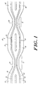
- Fig. 1 illustrates an asymmetric Mach-Zehnder interferometer (MZI) 10 according to the present invention.
- the MZI comprises two coupling regions 12, 14 separated by interfering arms 16, 18. More particularly in the embodiment illustrated, the MZI is formed from first and second optical fibers 20, 22 that are coupled at first and second asymmetric couplers 24, 26.
- a coupler is a device that splits the incoming optical energy between two output fibers.
- the first and second fibers 20, 22 form the interfering arms 16, 18 that connect the couplers 24, 26.
- a fiber Bragg grating (FBG) 25, 27 is written in the core 28, 30 of each of the interfering arms 16, 18 between the two couplers 24, 26.
- FBG fiber Bragg grating
- one fiber such as fiber 20
- the other fiber constitutes a drop or extract port 34
- the fiber 20 constitutes an add or insert port 36
- the fiber 22 constitutes an output or through port 38.
- the asymmetric couplers as well as the location of the fibers improves the spectral performance of the MZI.
- the electric field in the coupled port lags the electric field in the input port by a phase of ⁇ /2.
- the same phase relationship does not hold for the asymmetric coupler.
- the phase difference between the fields depends on the coupling strength and the degree of asymmetry.
- the constituent fibers have substantially identical propagation constants in the coupling region so that the coupling ratio can be 100%.
- the splitting ratio of the constituent couplers is substantially 50%.
- the splitting ratio of a symmetric coupler goes as the sine of the wavelength. The 50% point occurs at the quadrate of the wavelength response and hence is sensitive to small changes in wavelength.
- Fig. 2 illustrates a graph of measured spectral response of a typical symmetric coupler.
- the excess loss of the coupler was approximately 0.07 dB.
- the spikes are measurement artifacts from mode movement in the FP laser. From the graph, it can be seen that the wavelength variation in the region of interest (around the quadrate) is approximately 0.125%/nm. It is this large wavelength variation that reduces the isolation of the MZI to under 30 dB for spans greater than ⁇ 20 nm about the center wavelength.
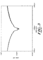
- Fig. 3 shows the measured spectral response of the add fiber in an MZI fabricated from typical symmetric couplers. From the graph, it can be seen that 30 dB isolation can be achieved in the add fiber over a wavelength range of 40 nm, which is a narrow wavelength range. The limited span of the 30 dB isolation region arises from the wavelength sensitivity of the couplers used to fabricate the MZI.
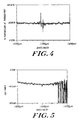
- Fig. 4 is a graph of measured spectral response of a typical asymmetric coupler. The excess loss of the coupler was approximately 0.09 dB. The spikes are measurement artifacts from mode movement in the FP laser. From the graph it can be seen that the wavelength variation in the region of interest is approximately 0.03%/nm. It is this reduced wavelength variation that allows 30 dB isolation in the through fiber to be achieved over spans greater than ⁇ 60 nm about the center wavelength. This is substantially greater than the span of ⁇ 20 nm achievable with the symmetric coupler discussed above.
- the most common method of fabricating the coupler is the fused taper method. For example, jackets of the two fibers are stripped for an appropriate length. The fibers are held together with the regions to be coupled maintained substantially parallel to each other and in contact. The coupling region is heated to a temperature of approximately 1700°C until they fuse together.
- the fibers may be heated with any suitable heat source, such as an electric arc, oxygen butane flame, or laser. As they are heated, the fibers are also drawn or stretched to create a narrowed or necked down or waist region. The tapering brings the fiber cores closer together, increasing the interaction between the signals.
- the asymmetry can be achieved by pre-tapering, etching or polishing one of the coupled fibers in the coupling region, or by bending the coupling region in the fiber plane.
- the asymmetry can also be achieved by fusing one of the fibers to a third glass rod or tube in the coupling region. The glass rod or tube raises the propagation constant of the fiber it is attached to in the coupling region. A combination of these techniques may also be used.
- Fig. 5 is a measured response of the add fiber of a MZI fabricated using asymmetric couplers. The spikes are measurement artifacts. From the graph, it can be seen that 30 dB isolation can be achieved in the add, or drop, fiber over a wavelength range of 120 nm, which is substantially larger than the 40 nm range achievable with the prior art symmetric MZI described above.
- the fiber Bragg gratings are written in the fiber cores in the two interfering arms.
- the fiber Bragg gratings may be written in any known manner. For example, using a photosensitive fiber, a silica phase mask having grooves etched thereon in the desired periodicity is placed close to the fiber. The fiber and mask are illuminated with an ultraviolet (UV) light source, such as a laser beam. The phase mask diffracts the light from the UV light source, creating multiple interfering beams. The UV light passes through the photo-sensitive fiber, altering the refractive index distribution therein and forming an FBG. In another technique to form an FBG, a UV laser beam is moved along the length of the fiber and turned on and off as it travels. Other techniques for writing the FBG may be used, such as interference holograms, interfering laser beams, or amplitude masks.
- UV ultraviolet
- Two embodiments are preferred in the present invention, a point symmetric MZI and a line symmetric MZI. Both embodiments may be used to fabricate the MZI and both may be used in conjunction with fiber Bragg gratings.
- a point symmetric MZI is one that is substantially symmetric about a point 40 in the middle of the interferometer arms.
- the fiber 20 in the coupling region 12 has a first propagation constant, preferably, the propagation constant of a standard fiber.
- the fiber 22 in the coupling region 12 is modified to have a different propagation constant.
- the fiber 22 in the coupling region 14 has the first or standard propagation constant.
- the fiber 20 in the coupling region 14 is modified to have a different propagation constant.
- a line symmetric MZI is one that is substantially symmetric about a line 42 through the interfering arms.
- One fiber, such as the fiber 20 has a first propagation constant, preferably the propagation constant of a standard fiber, at both the coupling region 12 and the coupling region 14.
- the other fiber, fiber 22, is modified to have a different propagation constant at both the coupling region 12 and the coupling region 14.
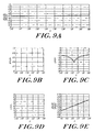
- the operation of the line symmetric MZI is described as follows, with reference to Figs. 9A-9E (the couplers are described in terms of transfer matrices and all the variables are given typical values):
- the coupler may be fabricated using polished or D-shaped fiber couplers.
- the asymmetry may be achieved by pretapering, etching or polishing one of the coupled fibers in the coupled region, or by bending the coupling region in the fiber plane.
- a combination of the techniques may also be used.
- the fibers used to fabricate the coupler need not necessarily be fused together as in the case of a polished block coupler.
- the interferometer may be fabricated from one or more photo-sensitive fibers.
- the coupler may be composed of more than two fibers.
- a 1x3 coupler may be fabricated wherein one or more of the fibers is photo-sensitive and the remaining fibers are photo-insensitive.
- the splitting ratio may be other than 50%.
- the maximum splitting ratio of the asymmetric couplers may be 40%.
- the MZI may be composed of a symmetric and an asymmetric coupler.
- the splitting ratio and the maximum splitting ratio of both couplers need not necessarily be the same.
- the interfering arms of the MZI need not necessarily be balanced.
- the structure may be used to make wavelength division multiplexers, with or without fiber Bragg gratings.
- the MZI may be constructed from three or more couplers, in which one or more of the couplers are asymmetric.
- the interfering arms of the MZI are different. By controlling the difference, the wavelength response of the output can be controlled.
Abstract
Description
- This application claims the benefit under 35 U.S C. § 119(e) of U.S. Application No. 60/101,592, filed on September 24, 1998, the disclosure of which is incorporated herein by reference.
- A wavelength division multiplexer/demultiplexer can be fabricated from a fiber optic Mach-Zehnder interferometer (MZI). The MZI is fabricated from a pair of symmetric couplers. Identical fiber Bragg gratings are written in the interfering arms between the couplers. A fiber Bragg grating (FBG) is a change in the refractive index in the fiber core that reflects a selective wavelength on the fiber.
- In operation of the MZI to drop or extract a wavelength, for example, as a demultiplexer, a signal carrying several channels or wavelengths λ1, λ2, λ3, λ4, and λ5 is input into the first fiber of the first coupler. Other numbers of channels, for example, 4 or 8 channels, may be input into the coupler. The signal is split at the coupler to pass along both arms. The FBGs, which are identical, are resonant at a selected frequency, for example, λ4. Thus, at the FBGs, λ4 is reflected, passes back through the first coupler, and is extracted or the second fiber of the first coupler. The remaining wavelengths, λ1, λ2, λ3, and λ5, pass through the second coupler and are output on the second fiber of the second coupler.
- In operation to add or insert a wavelength, for example, as a multiplexer, a signal having the wavelength λ4 is inserted on the first fiber at the second coupler. A signal of various wavelengths λ1, λ2, λ3, and λ5, is input into the first fiber of the first coupler. As described above with respect to the demultiplexer, λ4 is reflected at the FBGs. λ4 is then output on the second fiber of the second coupler. Thus, the output of the second coupler includes all the wavelengths, λ1, λ2, λ3, λ4, and λ5.
- In typical Mach-Zehnder interferometers fabricated from symmetric couplers, 30 dB isolation is limited to spans of ±20 nm about the desired wavelength.
- The present invention provides an optical fiber Mach-Zehnder interferometer fabricated from asymmetrical couplers, which allow 30 dB isolation over a wider wavelength range about a desired wavelength.
- More particularly, the asymmetric optical fiber Mach-Zehnder interferometer of the present invention comprises first and second optical fibers connected at a first coupling region and a second coupling region. The first and second optical fibers form two interfering arms between the first and second coupling regions. To form the asymmetry, the propagation constant in a portion of the first optical fiber in one of the coupling regions, for example, the first coupling region, differs from the propagation constant in a portion of the second optical fiber in that coupling region. The propagation constant in the first optical fiber and the propagation constant in the second optical fiber are chosen to provide 30 dB isolation in a through port of the Mach-Zehnder interferometer over a span of more than ±20 nm, and preferably more than ±60 nm, about a desired wavelength. The splitting ratio of the first coupling region is controlled to split the
power 50 percent at a desired wavelength. - The invention will be more fully understood from the following detailed description taken in conjunction with the accompanying drawings in which:
- Fig. 1 is a schematic illustration of an asymmetric Mach-Zehnder interferometer according to the present invention;
- Fig. 2 is a graph of the measured spectral response of a prior art symmetric coupler;
- Fig. 3 is a graph of the measured spectral response of the add fiber in a prior art Mach-Zehnder interferometer fabricated from symmetric couplers;
- Fig. 4 is a graph of the measured spectral response of an asymmetric coupler used in the present invention;
- Fig. 5 is a graph of the measured spectral response of a Mach-Zehnder interferometer according to the present invention;
- Fig. 6 is a schematic illustration of a point symmetric-Mach-Zehnder interferometer according to the present invention;
- Figs. 7A-7E are graphs illustrating operation of a point symmetric Mach-Zehnder interferometer according to the present invention;
- Fig. 8 is a schematic illustration of a line symmetric Mach-Zehnder interferometer according to the present invention; and
- Fig. 9A-9E are graphs illustrating operation of a line symmetric Mach-Zehnder interferometer according to the present invention.
-
- Fig. 1 illustrates an asymmetric Mach-Zehnder interferometer (MZI) 10 according to the present invention. The MZI comprises two
coupling regions arms optical fibers asymmetric couplers second fibers arms couplers core arms couplers fiber 20, constitutes an input orinsert port 32, and the other fiber,fiber 22, constitutes a drop orextract port 34. At the other side of the MZI, thefiber 20 constitutes an add orinsert port 36, and thefiber 22 constitutes an output or throughport 38. - In the present invention, the asymmetric couplers as well as the location of the fibers improves the spectral performance of the MZI. In a symmetric coupler, the electric field in the coupled port lags the electric field in the input port by a phase of π/2. The same phase relationship, however, does not hold for the asymmetric coupler. In an asymmetric coupler, the phase difference between the fields depends on the coupling strength and the degree of asymmetry.
- In a symmetric coupler, the constituent fibers have substantially identical propagation constants in the coupling region so that the coupling ratio can be 100%. In the fabrication of Mach-Zehnder interferometers, the splitting ratio of the constituent couplers is substantially 50%. The splitting ratio of a symmetric coupler goes as the sine of the wavelength. The 50% point occurs at the quadrate of the wavelength response and hence is sensitive to small changes in wavelength.
- Fig. 2 illustrates a graph of measured spectral response of a typical symmetric coupler. The excess loss of the coupler was approximately 0.07 dB. The spikes are measurement artifacts from mode movement in the FP laser. From the graph, it can be seen that the wavelength variation in the region of interest (around the quadrate) is approximately 0.125%/nm. It is this large wavelength variation that reduces the isolation of the MZI to under 30 dB for spans greater than ±20 nm about the center wavelength.
- Fig. 3 shows the measured spectral response of the add fiber in an MZI fabricated from typical symmetric couplers. From the graph, it can be seen that 30 dB isolation can be achieved in the add fiber over a wavelength range of 40 nm, which is a narrow wavelength range. The limited span of the 30 dB isolation region arises from the wavelength sensitivity of the couplers used to fabricate the MZI.
- In an asymmetric coupler, the propagation constants of the fibers are not identical in the coupling region. Thus, the maximum coupling ratio achievable is less than 100%. The splitting ratio of an asymmetric coupler also goes as the sine of the wavelength. However, the maximum splitting ratio call be controlled. Hence, in an asymmetric coupler, the 50% point can substantially occur at the maximum of the wavelength response and is thus less sensitive to changes in wavelength. Fig. 4 is a graph of measured spectral response of a typical asymmetric coupler. The excess loss of the coupler was approximately 0.09 dB. The spikes are measurement artifacts from mode movement in the FP laser. From the graph it can be seen that the wavelength variation in the region of interest is approximately 0.03%/nm. It is this reduced wavelength variation that allows 30 dB isolation in the through fiber to be achieved over spans greater than ±60 nm about the center wavelength. This is substantially greater than the span of ±20 nm achievable with the symmetric coupler discussed above.
- The most common method of fabricating the coupler is the fused taper method. For example, jackets of the two fibers are stripped for an appropriate length. The fibers are held together with the regions to be coupled maintained substantially parallel to each other and in contact. The coupling region is heated to a temperature of approximately 1700°C until they fuse together. The fibers may be heated with any suitable heat source, such as an electric arc, oxygen butane flame, or laser. As they are heated, the fibers are also drawn or stretched to create a narrowed or necked down or waist region. The tapering brings the fiber cores closer together, increasing the interaction between the signals.
- The asymmetry can be achieved by pre-tapering, etching or polishing one of the coupled fibers in the coupling region, or by bending the coupling region in the fiber plane. The asymmetry can also be achieved by fusing one of the fibers to a third glass rod or tube in the coupling region. The glass rod or tube raises the propagation constant of the fiber it is attached to in the coupling region. A combination of these techniques may also be used.
- The degree of asymmetry and coupling strength is controlled so that the maximum splitting ratio of the coupler is substantially 50%. Fig. 5 is a measured response of the add fiber of a MZI fabricated using asymmetric couplers. The spikes are measurement artifacts. From the graph, it can be seen that 30 dB isolation can be achieved in the add, or drop, fiber over a wavelength range of 120 nm, which is substantially larger than the 40 nm range achievable with the prior art symmetric MZI described above.
- After the two couplers are formed, the fiber Bragg gratings are written in the fiber cores in the two interfering arms. The fiber Bragg gratings may be written in any known manner. For example, using a photosensitive fiber, a silica phase mask having grooves etched thereon in the desired periodicity is placed close to the fiber. The fiber and mask are illuminated with an ultraviolet (UV) light source, such as a laser beam. The phase mask diffracts the light from the UV light source, creating multiple interfering beams. The UV light passes through the photo-sensitive fiber, altering the refractive index distribution therein and forming an FBG. In another technique to form an FBG, a UV laser beam is moved along the length of the fiber and turned on and off as it travels. Other techniques for writing the FBG may be used, such as interference holograms, interfering laser beams, or amplitude masks.
- Two embodiments are preferred in the present invention, a point symmetric MZI and a line symmetric MZI. Both embodiments may be used to fabricate the MZI and both may be used in conjunction with fiber Bragg gratings.
- Referring to Fig. 6, a point symmetric MZI is one that is substantially symmetric about a
point 40 in the middle of the interferometer arms. Thefiber 20 in thecoupling region 12 has a first propagation constant, preferably, the propagation constant of a standard fiber. Thefiber 22 in thecoupling region 12 is modified to have a different propagation constant. Thefiber 22 in thecoupling region 14 has the first or standard propagation constant. Thefiber 20 in thecoupling region 14 is modified to have a different propagation constant. - The operation of the point symmetric MZI is described as follows, with reference to Figs. 7A-7E (the couplers are described in terms of transfer matrices and all the variables are given typical values):

- Referring to Fig. 8, a line symmetric MZI is one that is substantially symmetric about a
line 42 through the interfering arms. One fiber, such as thefiber 20, has a first propagation constant, preferably the propagation constant of a standard fiber, at both thecoupling region 12 and thecoupling region 14. The other fiber,fiber 22, is modified to have a different propagation constant at both thecoupling region 12 and thecoupling region 14. The operation of the line symmetric MZI is described as follows, with reference to Figs. 9A-9E (the couplers are described in terms of transfer matrices and all the variables are given typical values):
- In the above equations and in Figs. 7A-7E and Figs. 9A-9E, the notation follows that of A.W. Snyder and J.D. Dove in Optical Waveguide Theory, published by Chapman and Hall. Note that in the line symmetric embodiment, the path lengths are not equal, indicated by 12:=10000.32265 and Δl=-0.323.
- As mentioned above, a number of alternate embodiments may be assembled for the present invention. For example, the coupler may be fabricated using polished or D-shaped fiber couplers. Once again, the asymmetry may be achieved by pretapering, etching or polishing one of the coupled fibers in the coupled region, or by bending the coupling region in the fiber plane. A combination of the techniques may also be used.
- The fibers used to fabricate the coupler need not necessarily be fused together as in the case of a polished block coupler. For instance, the interferometer may be fabricated from one or more photo-sensitive fibers. In addition, the coupler may be composed of more than two fibers. For example, a 1x3 coupler may be fabricated wherein one or more of the fibers is photo-sensitive and the remaining fibers are photo-insensitive. Moreover, the splitting ratio may be other than 50%. For example, the maximum splitting ratio of the asymmetric couplers may be 40%.
- The MZI may be composed of a symmetric and an asymmetric coupler. The splitting ratio and the maximum splitting ratio of both couplers need not necessarily be the same. Furthermore, the interfering arms of the MZI need not necessarily be balanced. Hence, the structure may be used to make wavelength division multiplexers, with or without fiber Bragg gratings. The MZI may be constructed from three or more couplers, in which one or more of the couplers are asymmetric. In another embodiment, the interfering arms of the MZI are different. By controlling the difference, the wavelength response of the output can be controlled.
- The invention is not to be limited by what has been particularly shown and described, except as indicated by the appended claims.
Claims (20)
- An asymmetric optical fiber Mach-Zehnder interferometer comprising:first and second optical fibers connected at a first coupling region and a second coupling region, the first and second optical fibers further forming two interfering arms between the first coupling region and the second coupling region;wherein a propagation constant in a portion of the first optical fiber in the first coupling region is different from a propagation constant in a portion of the second optical fiber in the first coupling region.
- The asymmetric optical fiber Mach-Zehnder interferometer of claim 1, wherein the first and second coupling regions comprise first and second fused taper couplers.
- The asymmetric optical fiber Mach-Zehnder interferometer of claim 1, wherein a splitting ratio of the first coupling region is controlled to split the power 50 percent at a desired wavelength.
- The asymmetric optical fiber Mach-Zehnder interferometer of claim 1, wherein the propagation constant in the first optical fiber and the propagation constant in the second optical fiber are chosen to provide 30 dB isolation in a through port of the Mach-Zehnder interferometer over a span of more than ±20 nm about a desired wavelength.
- The asymmetric optical fiber Mach-Zehnder interferometer of claim 4, wherein the propagation constant in the first optical fiber and the propagation constant in the second optical fiber are chosen to provide 30 dB isolation in a through port of the Mach-Zehnder interferometer over a span of more than ±60 nm about the desired wavelength.
- The asymmetric optical fiber Mach-Zehnder interferometer of claim 1, wherein a propagation constant in the first optical fiber in the second coupling region is different from a propagation constant in a portion of the second optical fiber in the second coupling region.
- The asymmetric optical fiber Mach-Zehnder interferometer of claim 1, wherein:the portion of the first optical fiber in the first coupling region has a first propagation constant; andthe portion of the second optical fiber in the first coupling region has a different propagation constant from the first propagation constant.
- The asymmetric optical fiber Mach-Zehnder interferometer of claim 7, wherein:a further portion of the first optical fiber in the second coupling region has the first propagation constant; anda further portion of the second optical fiber in the second coupling region has a different propagation constant from the first propagation constant.
- The asymmetric optical fiber Mach-Zehnder interferometer of claim 7, wherein:a further portion of the first optical fiber in the second coupling region has a different propagation constant from the first propagation constant; anda further portion of the second optical fiber in the second coupling region has the first propagation constant.
- The asymmetric optical fiber Mach-Zehnder interferometer of claim 1, wherein the propagation constant in the portion of the second optical fiber is provided by a pretapered, etched, or polished section of the second optical fiber.
- The asymmetric optical fiber Mach-Zehnder interferometer of claim 1, wherein the first and second fibers in the first coupling region are bent in a fiber plane to provide differing propagation constants.
- The asymmetric optical fiber Mach-Zehnder interferometer of claim 1, wherein a fiber Bragg grating is written in each of the two interfering arms.
- The asymmetric optical fiber Mach-Zehnder interferometer of claim 1, wherein the first and second optical fibers comprise polished optical fibers.
- The asymmetric optical fiber Mach-Zehnder interferometer of claim 1, wherein the first and second optical fibers comprise optical fibers having a D-shaped cross-section.
- The asymmetric optical fiber Mach-Zehnder interferometer of claim 1, further comprising a third optical fiber coupled to the first and second optical fibers at one of the first and second coupling regions.
- The asymmetric optical fiber Mach-Zehnder interferometer of claim 1, wherein at least one of the first and second optical fibers comprises a photo-sensitive fiber.
- The asymmetric optical fiber Mach-Zehnder interferometer of claim 1, wherein the first and second optical fibers are coupled at a third coupling region.
- The asymmetric optical fiber Mach-Zehnder interferometer of claim 1, wherein the two interfering arms are balanced.
- The asymmetric optical fiber Mach-Zehnder interferometer of claim 1, wherein the two interfering arms are unbalanced.
- A multiplexer/demultiplexer comprising the asymmetric optical fiber Mach-Zehnder interferometer of claim 1.
Applications Claiming Priority (2)
| Application Number | Priority Date | Filing Date | Title |
|---|---|---|---|
| US10159298P | 1998-09-24 | 1998-09-24 | |
| US101592P | 1998-09-24 |
Publications (2)
| Publication Number | Publication Date |
|---|---|
| EP0989423A2 true EP0989423A2 (en) | 2000-03-29 |
| EP0989423A3 EP0989423A3 (en) | 2001-11-07 |
Family
ID=22285449
Family Applications (1)
| Application Number | Title | Priority Date | Filing Date |
|---|---|---|---|
| EP99307547A Withdrawn EP0989423A3 (en) | 1998-09-24 | 1999-09-24 | Optical fiber mach-zehnder interferometer fabricated with asymmetric couplers |
Country Status (8)
| Country | Link |
|---|---|
| US (1) | US6226091B1 (en) |
| EP (1) | EP0989423A3 (en) |
| JP (1) | JP2000161910A (en) |
| KR (1) | KR20000023464A (en) |
| CN (1) | CN1251906A (en) |
| AR (1) | AR023905A1 (en) |
| BR (1) | BR9913820A (en) |
| CA (1) | CA2283361C (en) |
Cited By (3)
| Publication number | Priority date | Publication date | Assignee | Title |
|---|---|---|---|---|
| EP1202089A1 (en) * | 2000-10-31 | 2002-05-02 | PIRELLI CAVI E SISTEMI S.p.A. | Optical fibre filter |
| WO2009002255A1 (en) * | 2007-06-27 | 2008-12-31 | Syntune Ab | Mach zehnder modulator |
| EP3223049A1 (en) * | 2016-03-22 | 2017-09-27 | Huawei Technologies Co., Ltd. | Point-symmetric mach-zehnder-interferometer device |
Families Citing this family (11)
| Publication number | Priority date | Publication date | Assignee | Title |
|---|---|---|---|---|
| US6563971B1 (en) * | 1998-12-16 | 2003-05-13 | Alcoa Fujikura Limited | Optical fiber Mach-Zehnder interferometer employing miniature bends |
| CA2363806A1 (en) * | 2001-11-27 | 2003-05-27 | David R. Rolston | All fiber dynamic optical wavelength switch/filter device |
| CN1307404C (en) * | 2003-01-28 | 2007-03-28 | 电子科技大学 | Interference type optical fiber gyroscope based on MZ interference principle |
| WO2005003852A1 (en) * | 2003-07-04 | 2005-01-13 | Nippon Telegraph And Telephone Corporation | Interference optical switch and variable optical attenuator |
| KR100772557B1 (en) * | 2006-06-15 | 2007-11-02 | 경북대학교 산학협력단 | Apparatus for measurement based on micro-optic mach-zehnder interferometer |
| KR100863523B1 (en) * | 2007-04-16 | 2008-10-15 | 주식회사 피피아이 | Waveguide type optical splitter having the asymmetrical mach zhender structure of multimode type |
| US8643929B2 (en) * | 2010-01-12 | 2014-02-04 | Alcatel Lucent | Nested Mach-Zehnder modulator |
| JP2011253015A (en) * | 2010-06-01 | 2011-12-15 | Olympus Corp | Optical coupling device and mounting method thereof |
| WO2013052932A1 (en) * | 2011-10-06 | 2013-04-11 | Ofs Fitel, Llc | Broadband fiber sensor array |
| CN103267999B (en) * | 2013-06-01 | 2018-02-06 | 青岛农业大学 | Mach-Zehnder interferometer based on dumb-bell shape optical fiber structure |
| CN111998172A (en) * | 2019-05-27 | 2020-11-27 | 北京中创为南京量子通信技术有限公司 | Vibration-damping and heat-insulating device and vibration-damping and heat-insulating optical fiber interferometer equipment |
Citations (1)
| Publication number | Priority date | Publication date | Assignee | Title |
|---|---|---|---|---|
| US5048909A (en) * | 1990-07-27 | 1991-09-17 | At&T Bell Laboratories | Adiabatic reflection apparatus |
Family Cites Families (2)
| Publication number | Priority date | Publication date | Assignee | Title |
|---|---|---|---|---|
| US5875272A (en) * | 1995-10-27 | 1999-02-23 | Arroyo Optics, Inc. | Wavelength selective optical devices |
| US5841920A (en) | 1997-03-18 | 1998-11-24 | Lucent Technologies Inc. | Fiber grating package |
-
1999
- 1999-09-23 US US09/404,083 patent/US6226091B1/en not_active Expired - Lifetime
- 1999-09-24 AR ARP990104813A patent/AR023905A1/en not_active Application Discontinuation
- 1999-09-24 CA CA002283361A patent/CA2283361C/en not_active Expired - Fee Related
- 1999-09-24 BR BR9913820-4A patent/BR9913820A/en not_active IP Right Cessation
- 1999-09-24 JP JP11271131A patent/JP2000161910A/en active Pending
- 1999-09-24 EP EP99307547A patent/EP0989423A3/en not_active Withdrawn
- 1999-09-24 CN CN99123929A patent/CN1251906A/en active Pending
- 1999-09-27 KR KR1019990041322A patent/KR20000023464A/en not_active IP Right Cessation
Patent Citations (1)
| Publication number | Priority date | Publication date | Assignee | Title |
|---|---|---|---|---|
| US5048909A (en) * | 1990-07-27 | 1991-09-17 | At&T Bell Laboratories | Adiabatic reflection apparatus |
Non-Patent Citations (8)
| Title |
|---|
| CULLEN T J ET AL: "COMPACT ALL-FIBRE WAVELENGHT DROP AND INSERT FILTER" ELECTRONICS LETTERS, IEE STEVENAGE, GB, vol. 30, no. 25, 8 December 1994 (1994-12-08), pages 2160-2162, XP000502111 ISSN: 0013-5194 * |
| D.B. MORTIMORE: "WAVELENGTH-FLATTENED FUSED COUPLERS" ELECTRONICS LETTERS, vol. 21, no. 17, 15 August 1985 (1985-08-15), pages 74272-743, XP000997033 * |
| JOUANNO J-M ET AL: "LOW CROSSTALK PLANAR OPTICAL ADD-DROP MULTIPLEXER FABRICATED WITH UV-INDUCED BRAGG GRATINGS" ELECTRONICS LETTERS, IEE STEVENAGE, GB, vol. 33, no. 25, 4 December 1997 (1997-12-04), pages 2120-2121, XP000773570 ISSN: 0013-5194 * |
| JUMA S K ET AL: "IMPACT OF PHASE MASK TECHNIQUE IN GUIDED WAVE DEVICE PRODUCTION" PROCEEDINGS OF THE SPIE, SPIE, BELLINGHAM, VA, US, vol. 2997, 12 February 1997 (1997-02-12), pages 284-295, XP000199081 * |
| MALO B ET AL: "UNBALANCED DISSIMILAR-FIBRE MACH-ZEHNDER INTERFEROMETER: APPLICATION AS FILTER" ELECTRONICS LETTERS, IEE STEVENAGE, GB, vol. 25, no. 21, 12 October 1989 (1989-10-12), pages 1416-1417, XP000080100 ISSN: 0013-5194 * |
| MIZUOCHI T ET AL: "INTERFEROMETRIC CROSSTALK-FREE OPTICAL ADD/DROP MULTIPLEXER USING MACH-ZEHNDER-BASED FIBER GRATINGS" JOURNAL OF LIGHTWAVE TECHNOLOGY, IEEE. NEW YORK, US, vol. 16, no. 2, 1 February 1998 (1998-02-01), pages 265-276, XP000750668 ISSN: 0733-8724 * |
| MORISHITA K ET AL: "WAVELENGTH-INSENSITIVE COUPLERS IN FORM OF ALL-FIBRE MACH-ZEHNDER INTERFEROMETER" ELECTRONICS LETTERS, IEE STEVENAGE, GB, vol. 27, no. 13, 20 June 1991 (1991-06-20), pages 1200-1202, XP000238764 ISSN: 0013-5194 * |
| S. BETHUYS ET AL.: "Optical add/drop multiplexer based on UV-written Bragg gratings in twincore fibre Mach-Zehnder interferometer" ELECTRONICS LETTERS, vol. 34, no. 12, 11 June 1998 (1998-06-11), pages 1250-1252, XP002176191 * |
Cited By (6)
| Publication number | Priority date | Publication date | Assignee | Title |
|---|---|---|---|---|
| EP1202089A1 (en) * | 2000-10-31 | 2002-05-02 | PIRELLI CAVI E SISTEMI S.p.A. | Optical fibre filter |
| WO2002037150A1 (en) * | 2000-10-31 | 2002-05-10 | Pirelli S.P.A. | Optical fibre filter |
| US7177511B2 (en) | 2000-10-31 | 2007-02-13 | Pirelli S.P.A. | Optical fiber, optical fiber filter, and optical amplifier |
| WO2009002255A1 (en) * | 2007-06-27 | 2008-12-31 | Syntune Ab | Mach zehnder modulator |
| US8306370B2 (en) | 2007-06-27 | 2012-11-06 | Syntune Ab | Mach zehnder modulator |
| EP3223049A1 (en) * | 2016-03-22 | 2017-09-27 | Huawei Technologies Co., Ltd. | Point-symmetric mach-zehnder-interferometer device |
Also Published As
| Publication number | Publication date |
|---|---|
| CN1251906A (en) | 2000-05-03 |
| AR023905A1 (en) | 2002-09-04 |
| CA2283361C (en) | 2002-12-24 |
| CA2283361A1 (en) | 2000-03-24 |
| BR9913820A (en) | 2001-11-20 |
| KR20000023464A (en) | 2000-04-25 |
| US6226091B1 (en) | 2001-05-01 |
| EP0989423A3 (en) | 2001-11-07 |
| JP2000161910A (en) | 2000-06-16 |
Similar Documents
| Publication | Publication Date | Title |
|---|---|---|
| JP3022181B2 (en) | Waveguide type optical multiplexer / demultiplexer | |
| Bilodeau et al. | An all-fiber dense wavelength-division multiplexer/demultiplexer using photoimprinted Bragg gratings | |
| EP0791842B1 (en) | Article comprising a planar optical waveguide mach-zehnder interferometer device, and method of making same | |
| US5940556A (en) | Fiber-optic mode-routed add-drop filter | |
| US6091870A (en) | Wavelength division multiplexer/demultiplexer optical device | |
| EP0989423A2 (en) | Optical fiber mach-zehnder interferometer fabricated with asymmetric couplers | |
| JP3377729B2 (en) | Optical waveguide system | |
| JPH10206663A (en) | Light wave length uniter-brancher | |
| US5818987A (en) | Filter obtained by writing a Bragg grating into an optical fiber | |
| US20030048991A1 (en) | All-fiber mach-zehnder interferometer and method of making the same | |
| AU739755B2 (en) | Multi-band-pass filter | |
| JP4477260B2 (en) | Waveguide-type optical coupler and optical multiplexer / demultiplexer using the waveguide-type optical coupler | |
| KR100311281B1 (en) | Add-drop wavelength filter using mode discrimination couplers and tilted Bragg gratings | |
| US6212318B1 (en) | Add/drop filters and multiplexers fabricated from cladding mode couplers and fiber bragg gratings | |
| CA2231530C (en) | Grating-assisted fused fiber filter | |
| US6453094B1 (en) | All fiber DWDM multiplexer and demultiplexer | |
| Aslund et al. | Add-drop multiplexing by dispersion inverted interference coupling | |
| US6763155B2 (en) | Mach-zehnder interferomter (MZI) filter devices | |
| WO2003036352A2 (en) | Optical filter consisting of self-imaging multimode waveguide with apertures | |
| MXPA99008781A (en) | Mach-zehnder optical fiber interferometer manufactured with asimetri couplers | |
| Bures et al. | All-fiber dense wavelength division multiplexers | |
| Lacroix | Fused bitapered fiber devices for telecommunication and sensing systems | |
| Astharini et al. | Wavelength Shift in Single MZI as a Function of Arm Length Differences | |
| KR100633463B1 (en) | Optical add/drop multiplexer | |
| KR20000040493A (en) | Coupler type adding/detracting filter of optical communication system |
Legal Events
| Date | Code | Title | Description |
|---|---|---|---|
| PUAI | Public reference made under article 153(3) epc to a published international application that has entered the european phase |
Free format text: ORIGINAL CODE: 0009012 |
|
| AK | Designated contracting states |
Kind code of ref document: A2 Designated state(s): AT BE CH CY DE DK ES FI FR GB GR IE IT LI LU MC NL PT SE Kind code of ref document: A2 Designated state(s): DE FR GB IT |
|
| AX | Request for extension of the european patent |
Free format text: AL;LT;LV;MK;RO;SI |
|
| PUAL | Search report despatched |
Free format text: ORIGINAL CODE: 0009013 |
|
| RIC1 | Information provided on ipc code assigned before grant |
Free format text: 7G 02B 6/28 A, 7G 02F 1/313 B, 7G 02B 6/293 B |
|
| AK | Designated contracting states |
Kind code of ref document: A3 Designated state(s): AT BE CH CY DE DK ES FI FR GB GR IE IT LI LU MC NL PT SE |
|
| AX | Request for extension of the european patent |
Free format text: AL;LT;LV;MK;RO;SI |
|
| RAP1 | Party data changed (applicant data changed or rights of an application transferred) |
Owner name: THOMAS & BETTS INTERNATIONAL, INC. |
|
| AKX | Designation fees paid | ||
| RBV | Designated contracting states (corrected) |
Designated state(s): DE FR GB IT |
|
| REG | Reference to a national code |
Ref country code: DE Ref legal event code: 8566 |
|
| RAP1 | Party data changed (applicant data changed or rights of an application transferred) |
Owner name: ALCOA FUJIKURA LIMITED, (A DELAWARE CORPORATION) |
|
| 17P | Request for examination filed |
Effective date: 20020507 |
|
| RBV | Designated contracting states (corrected) |
Designated state(s): DE FR GB IT |
|
| 17Q | First examination report despatched |
Effective date: 20040921 |
|
| STAA | Information on the status of an ep patent application or granted ep patent |
Free format text: STATUS: THE APPLICATION IS DEEMED TO BE WITHDRAWN |
|
| 18D | Application deemed to be withdrawn |
Effective date: 20050202 |