EP0989351B1 - Support structure and display apparatus equipped therewith - Google Patents
Support structure and display apparatus equipped therewith Download PDFInfo
- Publication number
- EP0989351B1 EP0989351B1 EP99204303A EP99204303A EP0989351B1 EP 0989351 B1 EP0989351 B1 EP 0989351B1 EP 99204303 A EP99204303 A EP 99204303A EP 99204303 A EP99204303 A EP 99204303A EP 0989351 B1 EP0989351 B1 EP 0989351B1
- Authority
- EP
- European Patent Office
- Prior art keywords
- display unit
- support structure
- tilting
- torque
- downward
- Prior art date
- Legal status (The legal status is an assumption and is not a legal conclusion. Google has not performed a legal analysis and makes no representation as to the accuracy of the status listed.)
- Expired - Lifetime
Links
Images


Classifications
-
- F—MECHANICAL ENGINEERING; LIGHTING; HEATING; WEAPONS; BLASTING
- F16—ENGINEERING ELEMENTS AND UNITS; GENERAL MEASURES FOR PRODUCING AND MAINTAINING EFFECTIVE FUNCTIONING OF MACHINES OR INSTALLATIONS; THERMAL INSULATION IN GENERAL
- F16M—FRAMES, CASINGS OR BEDS OF ENGINES, MACHINES OR APPARATUS, NOT SPECIFIC TO ENGINES, MACHINES OR APPARATUS PROVIDED FOR ELSEWHERE; STANDS; SUPPORTS
- F16M11/00—Stands or trestles as supports for apparatus or articles placed thereon Stands for scientific apparatus such as gravitational force meters
- F16M11/02—Heads
- F16M11/04—Means for attachment of apparatus; Means allowing adjustment of the apparatus relatively to the stand
- F16M11/06—Means for attachment of apparatus; Means allowing adjustment of the apparatus relatively to the stand allowing pivoting
- F16M11/10—Means for attachment of apparatus; Means allowing adjustment of the apparatus relatively to the stand allowing pivoting around a horizontal axis
-
- F—MECHANICAL ENGINEERING; LIGHTING; HEATING; WEAPONS; BLASTING
- F16—ENGINEERING ELEMENTS AND UNITS; GENERAL MEASURES FOR PRODUCING AND MAINTAINING EFFECTIVE FUNCTIONING OF MACHINES OR INSTALLATIONS; THERMAL INSULATION IN GENERAL
- F16M—FRAMES, CASINGS OR BEDS OF ENGINES, MACHINES OR APPARATUS, NOT SPECIFIC TO ENGINES, MACHINES OR APPARATUS PROVIDED FOR ELSEWHERE; STANDS; SUPPORTS
- F16M11/00—Stands or trestles as supports for apparatus or articles placed thereon Stands for scientific apparatus such as gravitational force meters
- F16M11/20—Undercarriages with or without wheels
- F16M11/2007—Undercarriages with or without wheels comprising means allowing pivoting adjustment
- F16M11/2014—Undercarriages with or without wheels comprising means allowing pivoting adjustment around a vertical axis
-
- G—PHYSICS
- G06—COMPUTING; CALCULATING OR COUNTING
- G06F—ELECTRIC DIGITAL DATA PROCESSING
- G06F1/00—Details not covered by groups G06F3/00 - G06F13/00 and G06F21/00
- G06F1/16—Constructional details or arrangements
- G06F1/1601—Constructional details related to the housing of computer displays, e.g. of CRT monitors, of flat displays
-
- F—MECHANICAL ENGINEERING; LIGHTING; HEATING; WEAPONS; BLASTING
- F16—ENGINEERING ELEMENTS AND UNITS; GENERAL MEASURES FOR PRODUCING AND MAINTAINING EFFECTIVE FUNCTIONING OF MACHINES OR INSTALLATIONS; THERMAL INSULATION IN GENERAL
- F16M—FRAMES, CASINGS OR BEDS OF ENGINES, MACHINES OR APPARATUS, NOT SPECIFIC TO ENGINES, MACHINES OR APPARATUS PROVIDED FOR ELSEWHERE; STANDS; SUPPORTS
- F16M2200/00—Details of stands or supports
- F16M2200/04—Balancing means
- F16M2200/041—Balancing means for balancing rotational movement of the head
-
- G—PHYSICS
- G06—COMPUTING; CALCULATING OR COUNTING
- G06F—ELECTRIC DIGITAL DATA PROCESSING
- G06F2200/00—Indexing scheme relating to G06F1/04 - G06F1/32
- G06F2200/16—Indexing scheme relating to G06F1/16 - G06F1/18
- G06F2200/161—Indexing scheme relating to constructional details of the monitor
- G06F2200/1612—Flat panel monitor
-
- Y—GENERAL TAGGING OF NEW TECHNOLOGICAL DEVELOPMENTS; GENERAL TAGGING OF CROSS-SECTIONAL TECHNOLOGIES SPANNING OVER SEVERAL SECTIONS OF THE IPC; TECHNICAL SUBJECTS COVERED BY FORMER USPC CROSS-REFERENCE ART COLLECTIONS [XRACs] AND DIGESTS
- Y10—TECHNICAL SUBJECTS COVERED BY FORMER USPC
- Y10S—TECHNICAL SUBJECTS COVERED BY FORMER USPC CROSS-REFERENCE ART COLLECTIONS [XRACs] AND DIGESTS
- Y10S248/00—Supports
- Y10S248/917—Video display screen support
Definitions
- the present invention relates to a support structure including a tilting mechanism for tiltably supporting a body to be supported, such as a display unit; and also a display apparatus including the support structure such that a display unit can be vertically tilted without losing stability.
- a type including a tilting mechanism for adjusting a vertical inclination angle of a display unit whereby a display screen or surface of a display unit such as a CRT or a liquid crystal panel can assume not only an upright position but also a vertically inclined (tilted) position.
- a tilting mechanism namely an angle adjusting device, is described in United States Patent No. 5,354,028, which incorporates pairs of coil springs.
- the number of coil windings and/or winding directions can be selected so that the locking torques in both directions, forward and reverse, shall be the same. Alternatively, in a different design, they may be selected so that a larger locking torque is obtained in one direction and a smaller locking torque is obtained in another.
- a display apparatus is generally composed of a display unit having a display screen or surface and a support structure supporting the display unit. Tilting mechanisms are generally disposed between the display unit and the support structure and at positions in a manner of projecting laterally (i.e., leftward and rightward) out of the display unit to be recognizable from an operator side.
- the left and right tilting mechanisms are disposed to have an imaginary tilting axis which couples them and pierces the display unit laterally. An operator can tilt the display unit about the tilting axis and stably hold the display unit at a desired tilted angle.
- an operator can set the display screen at an arbitrary angle easy for recognition to have a better recognizability of characters or images on the display screen, e.g., by lightly pushing or pulling an upper end portion on the front face of the display unit.
- the display screen is given by a liquid crystal panel
- the recognizability of the display can be remarkably affected by an angle for viewing the display screen, so that such a tilting mechanism is important.
- the tilting axis is moved rearward along with the tilting mechanism, a large distance occurs between the gravity center and the tilting axis to provide a different or uneasy touch during the tilting operation. That is, in the operation for tilting the display unit, the tilting operation in the direction of the display unit weight is easy or light but the tilting in the opposite direction is heavy.
- the tilting is performed easily, i.e., at a light force, by pulling an upper front position of the display unit toward the operator side to direct the display screen downward, but a heavy force is required in the opposite tilting operation of pushing the upper front position away from the operator to direct the display screen upward.
- the upward and downward tilting operations require too large a difference in operation force, the operator can assume it as a trouble or failure.
- the uneasy touch during the tilting operation can be a serious problem in a trend of requiring a larger display unit.
- Such display apparatus there are some apparatus wherein the tilting or turning center of the display unit and the gravity center of the display apparatus are horizontally deviated from each other.
- the gravity center is moved forward and backward and also up and down.
- some display apparatus include a support structure allowing leftward and rightward lateral turning of the display unit. Further, some display apparatus include a display unit having a weight and a size exceeding those of the stand and post member of the support structure. In this case, when the display unit is laterally turned particularly in combination with a vertical tilting, the gravity center of the display apparatus is liable to be moved. Also, in this case, when the gravity center of the display unit is moved out of an effective supporting region formed by a setting surface on which the support base is disposed, the display apparatus is caused to fall down.
- a support structure capable of always stably supporting a display unit even if the display unit is vertically tilted or/and laterally turned within a maximum tolerable angle, and a display apparatus including such a support structure is also desired.
- a display apparatus including the support structure and a display unit supported by the support structure as a body to be supported.
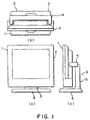
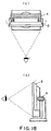
- FIGS 1A, 1B and 1C are a front view, a plan view and a side view, respectively, of a first embodiment of the display apparatus according to the present invention.
- a flat display apparatus 1 includes a flat display unit 2 (as a body to be supported), such as a plasma display, an electroluminescence display or a liquid crystal display (inclusive of those using a ferroelectric liquid crystal and a nematic liquid crystal), and a stand-type support structure 3 for supporting the display unit from its back.
- a flat display unit 2 as a body to be supported
- a plasma display such as a plasma display, an electroluminescence display or a liquid crystal display (inclusive of those using a ferroelectric liquid crystal and a nematic liquid crystal)
- a stand-type support structure 3 for supporting the display unit from its back.
- a support structure 3 according to the first embodiment will now be described.
- the support structure 3 is formed in the shape or roughly a laterally fallen character "H" as view from its back side, and its rotation or tilting center (pivot) is positioned behind the gravity center of a combination of the support structure 3 and the display unit 2 mounted thereon.
- the support structure 3 supports the display unit 2 so that the display unit 2 can assume an arbitrary angular position (i.e., a face direction) within prescribed vertical and lateral angular ranges.
- the support structure 3 includes a support base 6 and a stand support 5 turnably secured to the support base 6 so as to be turnable laterally at an arbitrary angle within a prescribed range.
- a display attachment member 4 for supporting the display unit 2 thereon is laterally mounted.
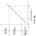
- the support structure 3 is designed to have a gravity center 33 which is deviated backward in a horizontal direction than the rotation or tilting center (pivot) 34 in a state not mounted with the display unit 2 as shown in Figure 45 and have a gravity center shifted and deviated horizontally forward than the pivot 34 when mounted with the display apparatus 2. Further, as will be described later, the support structure 3 is designed to obviate unnecessary electromagnetic radiation from the display unit.
- the support structure 3 in this embodiment is effective for avoiding the electromagnetic wave resonance, because the stand support 5 is formed by using an insulating material.
- the performance thereof may be evaluated in the following manner.
- a color ferroelectric liquid crystal display unit 2 driven at a maximum,clock pulse frequency of 20 MHz is mounted on such a support structure 3 provided with an anti-resonance measure regarding radiation interference wave (specific embodiments 1 - 3 described later) and a support structure provided with no anti-resonance measure (comparative example) and driven in an open site while the level of radiation interference wave is measured by an antenna standing at a point 10 m distant from the display apparatus.
- the measurement apparatus may have an organization as shown in Figure 49 including an antenna 41 for receiving radiation interference wave from the display unit 2, an amplifier 42 for amplifying the received signal, a spectrum analyzer 43 for indicating amplitudes of respective frequency components so as to effectively observe harmonic distortion, a recorder 44 for recording the overall frequency distribution of the radiation interference wave swept by the spectrum analyzer 43, and a receiver 45 disposed in parallel with the spectrum analyzer 43 and the recorder 44 for measuring the level of the radiation interference wave at a specific frequency.
- the antenna 41 may include a biconical antenna for a region of 30 MHz - 300 MHz and a logperiodic antenna for a higher frequency.
- the measurement may be performed as follows.
- the radiation interference wave received by the antenna 41 is swept for the entire wavelength region by the spectrum analyzer 42 to record the entire state of the radiation interference wave by the recorder. Then, for a specific frequency component, the level of the radiation interference wave is again accurately measured by the receiver 44 to examine whether the level is within a specified limit or not.
- the apparatus using the support structure with no anti-resonance measure provided an electromagnetic intensity distribution of vertical polarized plane wave as shown in Figure 47, whereas the apparatus using the support structure of the embodiment provided with the anti-resonance measure provided a result shown in Figure 48 (specific embodiment 1).
- the support structure with no anti-resonance measure caused radiation interference wave exceeding the VCCI level at some frequencies ( Figure 47), but the support structure 3 of this embodiment resulted in no radiation interference wave exceeding the level of the VCCI standard at any frequencies ( Figure 48).
- a support structure 3 as shown in Figure 3 was formed by supporting an insulating stand support 5 by a support base 6 and laterally mounting a display attachment member 4 at the upper end of the standard support.
- the support structure provided a result satisfying the VCCI standard as shown in Figure 48 while having satisfactory mechanical strength and production cost.
- the support arm 8 of the lateral attachment member was formed of an insulating synthetic resin. This type of support structure was satisfactory in respect of the VCCI standard, but the support arm showed a lower mechanical strength.
- the display attachment member 4 and the stand support 5 were connected via an electrically insulating member.
- the radiation interference wave showed a somewhat higher level than in the above embodiments 1 and 2 but satisfied the VCCI standard over the entire frequency region.
- the support stand 5 and the lateral attachment member 4 were both formed of metal.
- the support structure provided satisfactory mechanical strength and production cost, but the radiation interference wave exceeded the VCCI level.
- the above-described measurement was performed in an environment of 23 °C,by using a drive voltage of 20 volts and a frame frequency of ca. 15 Hz for repetitively displaying an "H" pattern as ordinarily used in radiation interference measurement.
- a support structure composed of a metal material may generally cause induced radiation with radiation interference wave, and a support structure having an antenna structure may amplify the radiation interference wave and electromagnetic wave of a particular frequency entering the support structure.
- a support structure 3 by using a member comprising an insulating material as in the above-described specific embodiments 1 - 3, it is possible to obviate the amplification of radiation interference wave or electromagnetic wave at a specific frequency, thus obtaining a result below the VCCI level.
- the display attachment member 4 in Figure 1 includes a tilting member (display holder) 7 having a planar shape of "U", a support body disposed outside and parallely with the display holder 7, and a resistance force-adjusting mechanism (tilting mechanism) 10r and 10 1 for tilting the display holder 7 with respect to the support body.
- the display attachment member 4 is designed to have a lateral width B2 which is narrower than a lateral width B1 of the display unit 2 ( Figure 19A) and a vertical length smaller than that of the display unit 2, so that the attachment member 4 is not observable when the display picture is viewed from the front of the display unit 2 ( Figures 18A and 18B). In other words, the display attachment member 4 is disposed within a whole projection area of the display unit 2.
- the display holder 7 comprises a metal member of, e.g., stainless steel for supporting the display unit ( Figures 1A - 1C). As shown in Figure 3, the display holder 7 is formed by leaving an intermediate portion 7a thereof so as to be disposed along the back of the display unit 2 and bending both side end portions to be opposite to the sides of the display unit 2 to form axis supporting parts 7r and 71. At upper edge portions of the intermediate portion 7a, engagement recesses 7b for engagement with projecting pins 202g projecting out of the back of the display unit 2 ( Figure 27) are formed. At lower portions of the intermediate member 7a, screw holes 7c for screwing the display holder 7 to the back of the display unit 2 are provided.
- a metal member of, e.g., stainless steel for supporting the display unit ( Figures 1A - 1C).
- the display holder 7 is formed by leaving an intermediate portion 7a thereof so as to be disposed along the back of the display unit 2 and bending both side end portions to be opposite to the sides of
- the above-mentioned support body is formed by a support arm 8 and upper and lower arm covers 9a and 9b for covering the support arm 8 from above and below the arm 8.
- the upper and lower arm covers 9a and 9b may be formed of a synthetic resin material, such as an acrylonitrile-styrene-butadiene copolymer (ABS).
- ABS acrylonitrile-styrene-butadiene copolymer
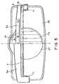
- the support arm 8 is formed to have a coupling portion or member 8a longer than the intermediate portion 7a of the display holder 7 and, at both lateral ends thereof, brackets 8r and 8 l are formed integrally so as to be opposite to the axis supporting parts 7r and 7 l as shown in Figure 5.
- the tilting mechanisms 10r and 10 l are fitted between the axis supporting parts 7r, 7 l of the display holder 7 and the brackets 8r, 8 l of the support arm 8.
- the right and left tilting mechanisms 10r and 10 l respectively include a laterally disposed axis member 12, a locked spring 13, and a bearing 14 holding one end of the locked spring 13 and also functioning as a rotation stopper, so that the locked springs 13 at both ends are disposed to have an identical winding direction.
- the rotation or tilting center (pivot) of the axis member 12 is designed to be at a position shifted horizontally backward from the gravity center of the display apparatus when the display unit 2 is mounted.
- the home position (normal position) of the display unit may be arbitrarily set to a position with an inclination at an arbitrary angle within a prescribed angle range or a vertical position.
- the locked spring 13 is formed to have an inner diameter smaller than the outer diameter of the axis member 12, and one end thereof extends through the stopper and bearing 14 to be engaged with the bracket 8r or 8 l .
- the other end of the locked spring 13 is made free whereas the elongation of the spring 13 is suppressed by a spring holder 15 through which the axis member 12 is inserted.
- the inner end of the axis member 12 is integrally screwed to the axis supporting port 7r (or 7 l ) via a washer 16, and the outer end thereof is rotatably supported by the stopper bearing 14 and the bracket 8r (or 8 l ).
- the locked spring 13 is wound about the axis member 12 so that its inner diameter is enlarged when the display holder 7 is turned upward (in an arrow A direction in Figure 26B) and the inner diameter is decreased when the display holder is turned downward (in an arrow B direction in Figure 26B).
- the turning or tilting direction of the tilting mechanisms is downward in case where the movement of the display unit 2 coincides with the direction of a torque WX about the axis member 12 caused by a weight W of the display unit and a bias X between the gravity center of the display unit 2 and the rotation center, and upward in the opposite direction.
- the tilting mechanisms 10r and 10 l are designed to generate a resisting downward torque Tr 1 which is exerted by the tilting mechanisms in resistance to an operation for turning the display unit upward by an arbitrary angle within a prescribed range, which torque Tr 1 is smaller than an upward torque Tr 2 which is exerted by the tilting mechanisms in response to an operation for turning the display unit downward by an arbitrary angle within a prescribed range.
- the difference in operation force between the upward tilting and downward tilting of the display unit is reduced to alleviate an uneasy touch in the tilting operation.
- the torque difference ⁇ T may be given by a combination of the right and left tilting mechanisms.
- the torque difference ⁇ T may be generated by a difference in direction of rotation of the axis member relative to the winding direction of the locked spring in the tilting mechanism as a resistance force-adjusting mechanism.
- a locked spring is fitted about the outer periphery of an axis member so as to lock its one end at the axis member.
- the diameter of the locked spring is reduced to provide an increased frictional force between the members.
- the diameter of the locked spring is enlarged to reduce the frictional force acting between the members.
- such a resistance force adjusting mechanism comprising a combination of a locked spring and an axis member is provided to the left and right ends of the tilting member while adjusting the winding directions of the locked springs at both ends.
- Each of the left and right resistance-force adjusting mechanisms can generate a torque difference ⁇ T so that the load of one mechanism can be reduced, and the tilting operation of the body to be supported can be smoothly performed.
- the display unit can be easily mounted on and detached from the support structure. Further, as the tilting mechanism is provided to the support structure side, the display unit need not be provided with a special mechanism for realizing a tilting operation but can be tilted by simply mounting it on the support structure.
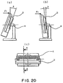
- the display unit 2 is designed to be tiltable by a prescribed angle ⁇ in the upward direction ( Figure 20A) and by a prescribed angle ⁇ in the downward direction ( Figure 20B).
- the coupling member 8a (or 8b) may be disposed at a position determined by the following formulae (1) and (2).
- Figure 21 which is a sectional view taken along a line A-A in Figure 20C
- the position of the axis member 12 is taken as the origin
- the forward-backward direction is taken on a Y-axis
- the vertical direction is taken on a Z-axis to define a Y-Z coordinate system.
- the upward and downward tiltable angles of the display panel of the display unit 2 are denoted by ⁇ and ⁇ , respectively
- the distance between the rear surface of the display unit 2 and the axis member 12 in the horizontal direction is denoted by t .
- the upward tiltable angle ⁇ is given by: Z ⁇ ⁇ (Y-t ⁇ cos ⁇ )/tan ⁇ - t ⁇ sin ⁇ and the downward tiltable angle ⁇ is given by: Z ⁇ ⁇ (t ⁇ cos ⁇ -Y)/tan ⁇ + t ⁇ sin ⁇ More specifically, the upward tiltable angle ⁇ may be set at 20 deg., and the downward tiltable angle ⁇ may be set at 5 deg. Based on the above formulae (1) and (2), it is possible to determine the allowable maximum size and strength of the support arm 8 and the upper and lower arm covers 9a and 9b for storing the tilting mechanisms 10r and 10 l .
- the tilting mechanisms 10r and 10 l are designed so that the own weight W of the display unit 2 causes a torque about the axis member 12 due to a forward bias of the gravity center acting in a direction of tightly winding the locked spring 13 to reduce the inner diameter of the spring 13, thereby tightly holding the axis member 12.
- the display unit 2 is not necessarily in a vertical position.
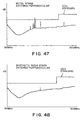
- the operational force F 1 for turning or tilting the display unit 2 may preferably be set within the range of 10 ⁇ F 1 ⁇ 40.
- the display unit can be tilted at a moderate operation force while obviating an unintentional movement at a small force.
- the display unit 2 is not necessarily in a vertical position.
- the axis member 12 is at a backwardly deviated position relative to the gravity center at any tilting state of the display unit 2
- the stand support 5 includes a post member 17 having a turnable base 17a at its root and a front post cover 18f and a rear post cover 18b covering the post member 17.
- the post member 17 may be formed from an unsaturated polyester resin compound of bulk-molding type, and the front and rear post covers 18f and 18b are formed from acrylonitrile-styrene-butadiene copolymer (ABS).
- an arm support plate 19 is attached and, at a lower part of the front post cover 18f, a stopper 20 is attached so as to be abutted by the lower end of the display unit 2 when the body is tilted downward.
- the lower surface of the turnable base 17a is provided with an axial projection 17b at its center and, along the periphery of the lower surface of the turnable base 17a, a fixed ring 21 of a metal, such as stainless steel, and a horizontal turn-assist ring 22 of polyacetal resin (assisting the turning of a post member-fixed plate combination) are arranged in this order. These members are pierced by the axial projection 17b.
- the fixed ring 21 is fixed surrounding the lower surface of the turnable base 17a.
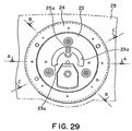
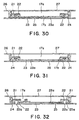
- a post member stopper plate 23 shown in Figure 29 having an outer diameter slightly larger than the inner diameter of the horizontal turn-assist ring 22 as shown in Figures 30 - 32 is attached, and the horizontal turn-assist ring 22 is inserted between the post member stopper plate 23 and the fixed ring 21.
- the horizontal turn-assist ring 22 is fixed to an assist ring support plate 24 as shown in Figure 31, and the horizontal turn-assist ring 22 and the ring support plate 24 are fixed to the stand base 25 as shown in Figure 30.
- the lower surface of the turn-assist ring 22 is provided with a plurality of bosses 22a as shown in Figure 32 so as to facilitate the assemblage of the turn-assist ring 22 and the stand base 25, so that the bosses 22a are fitted into fitting holes 25b formed in the stand base 25 through the turn-assist ring support plate 24.
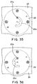
- the post member stopper 23 is provided with a crescent-shaped aperture 23a as shown in Figure 29.
- a turnable combination of the post member 17 and a disk-like member including the fixed ring 21 and the post member stopper plate 23, and a combination of the horizontal turn-assist ring 22, the assist ring support plate 24 and the stand base 25, are respectively integrated and separately turnable relative to the other. More specifically, a sliding surface is given between the fixed ring 21 and the horizontal turn-assist ring 22.
- the horizontally turn-assist ring 22 may be composed of polyacetal showing good self-lubricity to exhibit good slidability relative to the fixed ring 21 which is actually turnable together with the post member 17.
- the support structure 3 is formed by securing the stand support 5 horizontally or laterally turnable within prescribed angle range relative to the support base 6 and attaching the display attachment-member 4 so as to be tiltable up-and down-wardly to the stand support 5, whereby the display unit 2 is mounted securely onto the display attachment member 4.
- display unit 2 is supplied with electricity for displaying information or data inputted, e.g., from a key board of a main electronic apparatus.
- a cable 31 including a power cable and an interface cable has to be connected to the display unit 2.
- a character C-shaped clamp 32 as a cable clamping member is projectively attached to a lower part of the rear post cover 18b of the stand support 5 so as to prevent difficulties accompanying the provision of the cable 31, including the disorder of surrounding materials, such as cup and vases, on a place (such as a desk), and the insertion of the cable below the support stand 6.
- the plug 31a of the cable 31 may be connected to a socket disposed on the back of the display unit 2 while forming a loop with an intermediate portion of the cable 31 to clamp a part of the cable 31, whereby the connection from the other appliances to the display unit 2 is ensured without causing disorder by the cable.
- the cable neatly affixed to the stand support 5 is not moved vigorously to cause disorder or impair the stability of the support structure 3.
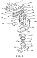
- the support base 6 is formed by covering the stand base 25 to which the horizontal turn-assist ring 22 and the assist ring support 24 are fixed as shown in Figure 33 with a base cover 26.
- the stand base 25 is provided with a projection 25a to be engaged with the aperture 23a of the post member stopper plate 23 shown in Figure 29 ( Figure 34).
- Figure 34 Figure 34
- the base cover 26 is provided with turnable base-accommodable aperture 26a ( Figure 2) through which the turnable base 17a is inserted, and a turning member cover 27 is fitted into the aperture 26a to close the aperture 26a.
- the stand base 25 is further provided with a slippage prevention seat 28 of, e.g., rubber or sponge, attached at its four corners so as to prevent the movement of the stand base 25 accompanying the lateral turning of the stand support 5.
- a slippage prevention seat 28 of, e.g., rubber or sponge, attached at its four corners so as to prevent the movement of the stand base 25 accompanying the lateral turning of the stand support 5.
- a relatively heavy display unit 2 may be attached, it is necessary to take care of ensuring the stability of the display apparatus 1 set on a surface inclined within an allowable extent even when the display unit 2 thereof is tilted vertically.
- a plurality of the slippage prevention seats (contacts) 28 are disposed to ensure the stability of the display apparatus 1. More specifically, the seats 28 placed on an inclined setting surface are projected onto a horizontal reference plane and the projected seats are connected successively to form an imaginary horizontal region defining an effective support region. Then, the display apparatus 1 is placed on a setting surface having a maximum tolerable slope angle ⁇ , and a vertical line is drawn from the gravity center of the display apparatus 1 to the horizontal reference plane.
- the slippage prevention seats 28 are disposed so that the vertical line drawn in the above-described manner always falls within the effective support region at any tilted position of the display unit 2.
- h 1 is taken as a height of the gravity center from the setting surface when the gravity center is at the frontmost position
- h 2 is taken as the high of the gravity center at the rearmost position
- X 4 is taken as a horizontal distance between the frontmost position and the rearmost position
- H is taken as an intersection of a vertical line from the gravity center and the effective support region.
- D X 4 + (h 1 +h 2 )tan ⁇
- the angles ⁇ , ⁇ 2 and ⁇ 2 may preferably have a value of ca. 10 deg. and may be set to ca. 15 deg. as design values including a margin.
- the support structure 3 includes a stand support 5 turnable about a vertical axis standing upright relative to the support base 6, and the stand support 5 includes a disk-shaped unit having a peripheral portion turnable relative to the support 6.
- the disk-shaped unit has a diameter d which is set to be smaller than the width of the effective supporting region D.
- the angles ⁇ , ⁇ 3 and ⁇ 4 may preferably have a value of ca. 10 deg. and may be set to ca. 15 deg. as design values including a margin.
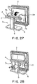
- the display unit 2 may be mounted on the display holder 7 by engaging the pins 27 with the recesses 7b of the display holder 7 ( Figure 27), and then screwing the display unit 2 and the display holder 7 to each other ( Figure 28).
- the torque occurring about the axis member 12 due to the forward deviation X of the gravity center from the axis member 12 and the own weight W of the display unit 2 acts in a direction of tightly winding the locked spring 13 to decrease the inner diameter of the locked spring 13 and tighten the axis member 12, whereby the display unit is held in position due to the frictional force acting between the locked spring 31 and the axis member 12.
- an application point U 1 at the upper end of the display unit 2 may be pushed at an operation force F 1 exceeding a prescribed value.
- the operation force F 1 acting on the point U 1 turns the axis member 12 via the display holder 7 in a direction of enlarging the inner diameter of the locked spring 13.
- the pressure contact force acting onto the axis member 12 is reduced to reduce the resisting downward torque Tr 1 occurring in resistance to upward tilting of the display unit 2, so that the upward turning operation force F 1 becomes larger than the downward torque Tr 1 and the torque WX based on the own weight of the display unit 2 to allow an upward tilting of the display unit 2.
- the display unit 2 During the pushing of the display unit 2 at an operating force F 1 exceeding the prescribed value, the display unit 2 is turned upward. Thereafter, when the operation force F 1 is released, the internal diameter of the locked spring 13 is reduced to restore the original pressure contact force against the axis member 12, whereby the display unit 2 is stopped at a position where the operation force F 1 is released.
- an application point D 1 at the lower end of the display unit 2 may also be pushed at an operation force F 1 exceeding a prescribed value.
- the operation force F 1 acting on the point D 1 turns the axis member 12 via the display holder 7 in a direction of enlarging the inner diameter of the locked spring 13.
- the pressure contact force acting onto the axis member 12 is reduced to reduce the resisting downward torque Tr 1 occurring in resistance to upward tilting of the display apparatus main body 2, so that the upward turning operation force F 1 becomes larger than the downward torque Tr 1 and the torque WX based on the own weight of the display unit 2 to allow an upward tilting of the display unit 2.
- the display unit 2 During the pushing of the display unit 2 at an operating force F 1 exceeding the prescribed value, the display unit 2 is turned upward. Thereafter, when the operation force F 1 is released, the internal diameter of the locked spring 13 is reduced to restore the original pressure contact force against the axis member 12, whereby the display unit 2 is stopped at a position where the operation force F 1 is released.
- the display unit 2 can be tilted upward to an arbitrary position by applying an operation force F 1 exceeding a prescribed resisting force including a downward resisting torque Tr 1 . Further, by abutment of the back surface of the display unit 2 against the,coupling member 8a of the support arm 8, a further upward turning of the display unit 2 is regulated.
- an application point U 2 at the upper end of the display unit 2 may be pushed at an operation force F 2 exceeding a prescribed value.
- the operation force F 2 acting on the point U 2 turns the axis member 12 via the display holder 7 in a direction of decreasing the inner diameter of the locked spring 13.
- the pressure contact force and frictional force acting onto the axis member 12 are increased to increase the resisting upward torque Tr 2 .
- the torque WX based on the own weight of the display unit 2 is added to the downward turning operation force F 2 to exceed the upward torque Tr 2 , thereby allowing a downward tilting of the display unit 2.
- the display unit 2 During the pushing of the display unit 2 at an operating force F 2 exceeding the prescribed value, the display unit 2 is turned downward. Thereafter, when the operation force F 2 is released, the internal diameter of the locked spring 13 is restored to the original value, and the display unit 2 is stopped at a position where the operation force F 2 is released.
- an application point D 2 at the lower end of the display unit 2 may also be pushed at an operation force F 2 exceeding a prescribed value.
- the operation force F 2 acting on the point D 2 turns the axis member 12 via the display holder 7 in a direction of decreasing the inner diameter of the locked spring 13.
- the pressure contact force and frictional force acting onto the axis member 12 are increased to increase the resisting upward torque Tr 2 .
- the torque WX based on the own weight of the display unit 2 is added to the downward turning operation force F 2 to exceed the upward torque Tr 2 , thereby allowing a downward tilting of the display unit 2.
- the display unit 2 During the pushing of the display unit 2 at an operating force F 2 exceeding the prescribed value, the display unit 2 is turned downward. Thereafter, when the operation force F 2 is released, the internal diameter of the locked spring 13 is restored to the original value, and the display unit 2 is stopped at a position where the operation force F 2 is released.
- the display unit 2 can be tilted downward to an arbitrary position by applying an operation force F 2 exceeding a prescribed resisting force including an upward resisting torque Tr 2 . Further, by abutment of the back surface of the display unit 2 against the stopper 20 of the stand support 5, a further downward turning of the display unit 2 is regulated.
- the display unit 2 can be tilted upward and downward at almost equal operation forces.
- the tilting may be performed smoothly, and the display unit 2 can be placed in an arbitrary tilted position within a prescribed angle.
- an operation force may be applied to an application point on a side of the display unit 2 to turn the body 2 relative to the support structure 3.
- the horizontal turn-assist ring 22 is inserted between the post member stopper plate 23 and the fixed ring 21 affixed to the post member 17, and the horizontal turn-assist ring 22 and the assist ring support plate 24 are fixed to the stand base 25. Further, the projection 25a of the stand base 25 is inserted into the aperture 23a in the post member stopper plate 23.
- the display panel of the display unit 2 may be turned leftwards, for example, by turning the crescent-shaped post member stopper plate 23 so a to slide its aperture 23a along the projection 25 (which is initially positioned at the center of the crescent aperture 23a) as shown in Figure 35 whereby the display unit 2 can be turned clockwise by nearly 90 deg.
- the display unit 2 may be turned rightwards by turning the stopper plate 23 so as to slide its aperture along the projection 25a of the stand base 25, whereby the display unit 2 can be turned counterclockwise by nearly 90 deg.
- the gravity center of the display apparatus can be retained within the effective support region of the support base even if the display unit is turned by 90 deg. either leftwards or rightwards provided that the support 6 is placed on a setting surface within a tolerable slope angle range. As a result, a stable turning in lateral directions of the display unit is ensured.
- the second embodiment is directed to a display apparatus having a tilt axis (axis member) deviated forward from its gravity center.
- the display apparatus includes a stand support 30 of which an upper end provides a bearing and, between the bearing and the lateral sides (left side and right side) of the display unit 2, tilting mechanisms 10 (10r and 10 l ) identical to those used in the above first embodiment are installed.
- the tilting mechanisms 10 are installed on the lateral sides of the housing of the display unit 2, and the left and right locked springs are wound about left and axis members in an identical winding direction.
- the display unit 2 includes relatively heavy components, such as a drive circuit and a control circuit in its rear side projecting rearward from the axis member, so that the gravity center of the display unit 2 is deviated rather backward than the axis member.
- each tilting mechanism is so designed that the own weight of the display unit 2 causes a torque WX about the axis member due to a rearward bias of the gravity center acting in a direction of tightly winding the locked spring to reduce the inner diameter of the locked spring, thereby tightly holding the axis member. Accordingly, the display unit 2 is stopped in its home position due to a frictional force of the locked spring acting on the axis member.
- the tilting mechanisms 10 are so designed that the axis member is turned relative to the locked spring, thereby enlarging the inner diameter of the locked spring to reduce the pressure contact force acting onto the axis member.
- the upward resisting torque Tr 1 is reduced, so that the torque caused by the downward tilting operation force F 1 becomes larger than the upward generated torque Tr 1 and the torque WX caused by the own weight of the display unit 2, whereby the display unit 2 is tilted downward.
- the tilting mechanisms 10 are so designed that the axis member is turned relative to the locked spring in a direction opposite to the winding direction of the locked spring, thereby reducing the inner diameter of the locked spring to increase the pressure contact force acting onto the axis member.
- the moment WX based on the own weight of the display unit 2 is added to the operation force F 2 to exceed the generated downward resisting torque Tr 2 , the display unit 2 can be tilted upward by the operation force F 2 .
- the torque occurring about the axis member due to the rearward deviation of the gravity center from the axis member and the own weight of the display unit 2 acts in a direction of tightly winding the locked spring to decrease the inner diameter of the spring and tighten the axis member, whereby the display unit 2 is held in position due to the frictional force acting between the locked spring and the axis member.
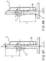
- an application point U 1 at the upper end of the display unit 2 may be pushed at an operation force F 1 exceeding a prescribed value.
- the operation force F 1 acting on the point U 1 turns the axis member in a direction of enlarging the inner diameter of the locked spring.
- the pressure contact force acting on the axis member is reduced to reduce the resisting upward torque Tr 1 occurring in resistance to downward tilting of the display unit 2, so that the downward tilting operation force F 1 exceeds the resisting upward torque Tr 1 and the torque based on the own weight W of the display unit 2 to allow a downward tilting of the display unit 2.
- the display unit is turned downward. Thereafter, when the operation force F 1 is released, the internal diameter of the locked spring is reduced to restore the original pressure contact force acting on the axis member, whereby the display unit 2 is stopped at a position when the operation force F 1 is released.
- an application point D 1 at the lower end of the display unit 2 may be pushed at an operation force F 1 exceeding a prescribed value.
- the operation force F 1 acting on the point D 1 turns the axis member in a direction of enlarging the inner diameter of the locked spring.
- the pressure contact force acting on the axis member is reduced to reduce the resisting upward torque Tr 1 occurring in resistance to downward tilting of the display unit 2, so that the downward tilting operation force F 1 exceeds the resisting upward torque Tr 1 and the torque based on the own weight W of the display unit 2 to allow a downward tilting of the display unit 2.
- the display unit is turned downward. Thereafter, when the operation force F 1 is released, the internal diameter of the locked spring is reduced to restore the original pressure contact force acting on the axis member, whereby the display unit 2 is stopped at a position when the operation force F 1 is released.
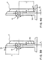
- an application point U 2 at the upper end of the display unit 2 may be pushed at an operation force F 2 exceeding a prescribed value.
- the operation force F 2 acting on the point U 2 turns the axis member in a direction of reducing the inner diameter of the locked spring.
- the pressure contact force acting on the axis member is increased to increase the resisting downward torque Tr 2 .
- the torque based on the own weight W of the display unit 2 is added to the operation force F 2 to exceed the resisting downward torque Tr 2 thereby allowing an upward tilting of the display unit 2 by the operation force F 2 .
- the display unit is turned downward. Thereafter, when the operation force F 2 is released, the internal diameter of the locked spring is reduced to restore the original pressure contact force acting on the axis member, whereby the display unit 2 is stopped at a position when the operation force F 2 is released.
- an application point D 2 at the upper end of the display unit 2 may be pushed at an operation force F 2 exceeding a prescribed value.
- the operation force F 2 acting on the point D 2 turns the axis member in a direction of reducing the inner diameter of the locked spring.
- the pressure contact force acting on the axis member is increased to increase the resisting downward torque Tr 2 .
- the torque based on the own weight W of the display unit 2 is added to the operation force F 2 to exceed the resisting downward torque Tr 2 thereby allowing an upward tilting of the display unit 2 by the operation force F 2 .
- the display unit is turned downward. Thereafter, when the operation force F 2 is released, the internal diameter of the locked spring is reduced to restore the original pressure contact force acting on the axis member, whereby the display unit 2 is stopped at a position when the operation force F 2 is released.
- the support structure has been described with reference to a stand type wherein the support structure body (display attachment) member is supported by a stand support 5 and a support base 6.
- the support structure according to the present invention can be composed as a type wherein the support structure is hanged on a wall or hanged down from a higher point.
- the support structure as described in detail above, is suitable for supporting a display unit as a body to be supported as in the above embodiments but can be also applicable to other types of bodies to be supported.
- the support structure is composed by a stand support held upright by a support base and an attachment member for attaching a body to be supported laterally mounted on the stand support, it is possible to provide a sufficient mechanical strength by a simple structure.
- the support structure is constituted to generate a downward resisting torque generated in resistance to an operation force for upwardly tilting a body to be supported in a direction opposite to a torque caused by an own weight of the body, and an upward resisting torque generated in resistance to an operation force for downwardly tilting the body to be supported, such that the downward resisting torque is smaller than the upward resisting torque.
- the difference in operation force between upward tilting and downward tilting is decreased to alleviate an uneasy touch during the tilting operation.
- the torque difference ⁇ T is set depending on WX to further reduce the difference in operation between the upward and downward tilting.
- the support structure stands upright even when it does not support a body to be supported, so that it is easy to mount or install the body thereon.
- the laterally pairing tilting mechanisms are so constituted that the locked springs thereat are wound in an identical direction, whereby each tilting mechanism is required to generate a smaller torque and can be reduced in size, thereby reducing the entire support structure in size.
- the operation force is set within a range of 10 ⁇ F ⁇ 40 (N), it is possible to obviate a difficulty that the supported body is tilted unintentionally at a small force, or too large an operation force is required for tilting the supported body.
- the attachment member can be disposed within a projection area of the body to be supported, so that the attachment member is free from providing an uneasy appearance even when the body to be supported is a display unit.
Description
- The present invention relates to a support structure including a tilting mechanism for tiltably supporting a body to be supported, such as a display unit; and also a display apparatus including the support structure such that a display unit can be vertically tilted without losing stability.
- As a support structure for display apparatus for personal computer or word processors, there has been known a type including a tilting mechanism for adjusting a vertical inclination angle of a display unit, whereby a display screen or surface of a display unit such as a CRT or a liquid crystal panel can assume not only an upright position but also a vertically inclined (tilted) position.
- A tilting mechanism, namely an angle adjusting device, is described in United States Patent No. 5,354,028, which incorporates pairs of coil springs. The number of coil windings and/or winding directions can be selected so that the locking torques in both directions, forward and reverse, shall be the same. Alternatively, in a different design, they may be selected so that a larger locking torque is obtained in one direction and a smaller locking torque is obtained in another.
- A display apparatus is generally composed of a display unit having a display screen or surface and a support structure supporting the display unit. Tilting mechanisms are generally disposed between the display unit and the support structure and at positions in a manner of projecting laterally (i.e., leftward and rightward) out of the display unit to be recognizable from an operator side. The left and right tilting mechanisms are disposed to have an imaginary tilting axis which couples them and pierces the display unit laterally. An operator can tilt the display unit about the tilting axis and stably hold the display unit at a desired tilted angle. Thus, an operator can set the display screen at an arbitrary angle easy for recognition to have a better recognizability of characters or images on the display screen, e.g., by lightly pushing or pulling an upper end portion on the front face of the display unit. For example, in case where the display screen is given by a liquid crystal panel, the recognizability of the display can be remarkably affected by an angle for viewing the display screen, so that such a tilting mechanism is important.
- In recent years there is a trend of requiring a larger area display unit, whereas a support structure as an accessory device for the display unit is required to be further smaller in size. This means that the necessary unit is large enough, but the other member is minimized within a possible extent, e.g., so as to reduce an area on a desk occupied by the display apparatus.
- In the above-mentioned display apparatus, however, as the tilting mechanisms disposed at the left and right sides project leftward and outward, respectively, out of the sides of the display unit, it is difficult to further reduce the lateral width of the support structure alone and also of the whole display apparatus.
- As a solution to the above-difficulty, it may be conceived of to move the left and right tilting mechanisms from the lateral sides to the back of the display unit. By this measure, it is possible to hide the tilting mechanisms from the viewing field of a display apparatus operator and provide a better design appearance. As a result of the above measure, however, the tilting axis is moved rearward along with the tilting mechanism, a large distance occurs between the gravity center and the tilting axis to provide a different or uneasy touch during the tilting operation. That is, in the operation for tilting the display unit, the tilting operation in the direction of the display unit weight is easy or light but the tilting in the opposite direction is heavy. More specifically, in the case where the tilting axis is shifted rearward from the gravity center of the display unit, the tilting is performed easily, i.e., at a light force, by pulling an upper front position of the display unit toward the operator side to direct the display screen downward, but a heavy force is required in the opposite tilting operation of pushing the upper front position away from the operator to direct the display screen upward. In case where the upward and downward tilting operations require too large a difference in operation force, the operator can assume it as a trouble or failure. The uneasy touch during the tilting operation can be a serious problem in a trend of requiring a larger display unit.
- Among such display apparatus, there are some apparatus wherein the tilting or turning center of the display unit and the gravity center of the display apparatus are horizontally deviated from each other. In such display apparatus, when the display unit is vertically tilted up and down, the gravity center is moved forward and backward and also up and down.
- In such display apparatus, when the gravity center goes out of an effective support region formed by a setting surface on which the support base is disposed, the display apparatus is caused to fall down. This difficulty becomes more serious in view of the above-mentioned requirement for a smaller support structure.
- On the other hand, some display apparatus include a support structure allowing leftward and rightward lateral turning of the display unit. Further, some display apparatus include a display unit having a weight and a size exceeding those of the stand and post member of the support structure. In this case, when the display unit is laterally turned particularly in combination with a vertical tilting, the gravity center of the display apparatus is liable to be moved. Also, in this case, when the gravity center of the display unit is moved out of an effective supporting region formed by a setting surface on which the support base is disposed, the display apparatus is caused to fall down.
- Accordingly, there has been desired a support structure capable of always stably supporting a display unit even if the display unit is vertically tilted or/and laterally turned within a maximum tolerable angle, and a display apparatus including such a support structure is also desired.
- It is intended to provide a support structure allowing a further reduction in lateral size of an apparatus including the support structure and also reducing or eliminating an uneasy touch during a tilting operation of a display unit, and also a display apparatus having good observability including such a support structure.
- It is also intended to provide a display apparatus including a display unit supported in an upright position wherein the display unit can be stably held even when it is vertically tilted within maximum tolerable angles.
- According to the present invention, there is provided a support structure as defined in claim 1.
- As a result, it is possible to reduce a difference in tilting operation force between upward and downward tilting operations, thus reducing an uneasy touch during the tilting operation of the body to be supported.
- According to the present invention, there is also provided a display apparatus including the support structure and a display unit supported by the support structure as a body to be supported.
- These and other advantages of the present invention will become more apparent upon a consideration of the following description of the preferred embodiments of the present invention taken in conjunction with the accompanying drawings of which:
- Figures 1A, 1B and 1C are a front view, a top plan view and a side view, respectively, of a first embodiment of the display apparatus including a support structure according to the invention;
- Figure 2 is an exploded perspective view of the support structure;
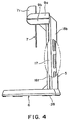
- Figures 3, 4 and 5 are a front view, a side view and a plan view, respectively, of the support structure;
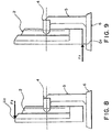
- Figures 6 and 7 are schematic side views showing points of application at an upper end and a lower end, respectively, of a display unit mounted on a support structure according to the first embodiment;
- Figures 8 and 9 are schematic side views showing points of application at an upper end and a lower end, respectively, of a display unit mounted on a support structure;
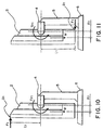
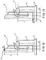
- Figures 10 - 13 are respectively a schematic side view of a display apparatus for illustrating an operation when an operation force is applied to an indicated application point (corresponding to those shown in Figures 6 - 9, respectively).
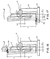
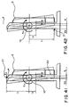
- Figures 14 - 17 are respectively an operational illustration for illustrating an operation force, a torque occurring on an axial member and moment occurring based on its own weight (corresponding to Figures 6 - 9, respectively).
- Figures 18A and 18B are a schematic plan view and a schematic side view, respectively, of a combination of a display unit and a support structure for illustrating a positional relationship.
- Figures 19A and 19B are a schematic plan view and a schematic side view, respectively, of a combination of a display unit and a support structure for illustrating a size relationship.
- Figures 20A - 20C are illustrations of a display apparatus due to an up-and-down movement including Figure 20A showing an upwardly inclinable range, Figure 20B showing a downwardly inclinable range and Figure 20C showing a home position, respectively, of a display unit.
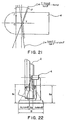
- Figure 21 is an illustration of an inclinable range of a section taken along a line A-A in Figure 20C.
- Figure 22 is an illustration for defining a depth D of a support stand.
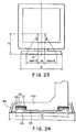
- Figure 23 is an illustration for giving a definition of width B of a support stand.
- Figure 24 is a partial side view for illustrating a turning base diameter and a support stand depth.
- Figure 25 is a rear perspective view of a display apparatus.
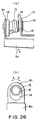
- Figure 26A is a partial plan view showing a tilting mechanism, and Figure 26B is a sectional view taken along a line b-b in Figure 26A.
- Figure 27 is a perspective view for illustrating a manner of mounting and detaching of a display unit on and from a tilting member of a support structure.
- Figure 28 is a perspective view showing a display unit mounted on a tilting member.
- Figure 29 is a plan view showing a post member-stopper plate.
- Figures 30 - 32 are sectional views taken along line A-A, line B-B and line C-C, respectively, shown in Figure 29.
- Figure 33 is a bottom plan view of a support stand base.
- Figure 34 is a sectional view taken along line D-D in Figure 33.
- Figures 35 and 36 show states where a post member-stopper plate is turned clockwise and counterclockwise, respectively, with respect to a support stand base.
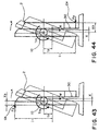
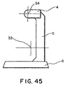
- Figures 37 and 38 are schematic side views for illustrating downward tilting by application of operation forces at an upper end and a lower end, respectively, of a display unit in a display apparatus including a support structure according to a second embodiment.
- Figures 39 and 40 are schematic side views for illustrating upward tilting by application of operation forces at an upper end and a lower end, respectively, of the display unit.
- Figures 41 - 44 are respectively an operational illustration for illustrating an operation force, a torque occurring on an axial member and a moment occurring based on an own weight of the display unit (corresponding to Figures 37 - 40, respectively).
- Figure 45 is a side view of a support structure alone.
- Figure 46 is a view for illustrating a set range for operation force.
- Figures 47 and 48 show measured electromagnetic intensity distributions in cases where a counter-measure for preventing resonance with obstructing radiation is not taken and is taken, respectively.
- Figure 49 is a block diagram of an instrument for measuring an electromagnetic field intensity.
-
- Incidentally, some reference numerals representing major components or members shown in the accompanying drawings are remarked hereinbelow.
- 2
- body to be supported (display unit),
- 3
- support structure,
- 4
- support structure body (display attachment member),
- 6
- support base,
- 7
- tilting member (display holder),
- 8
- support arm,
- 10, 10r, 10l
- tilting mechanism (resistance force adjusting mechanism),
- 12
- axis member (tilt axis, pivot),
- 13
- locked spring,
- W
- weight of display unit,
- X, X1, X2
- deviation,
- Tr1
- downward torque,
- Tr2
- upward torque,
- ΔT
- torque difference,
- F1, F2
- operation force,
- l 1
- vertical distance from a tilt axis to an application point,
- l 2
- vertical distance from a tilt axis to a gravity center.
- Figures 1A, 1B and 1C are a front view, a plan view and a side view, respectively, of a first embodiment of the display apparatus according to the present invention. Referring to Figures 1A - 1C, a flat display apparatus 1 includes a flat display unit 2 (as a body to be supported), such as a plasma display, an electroluminescence display or a liquid crystal display (inclusive of those using a ferroelectric liquid crystal and a nematic liquid crystal), and a stand-type support structure 3 for supporting the display unit from its back.
- A support structure 3 according to the first embodiment will now be described.
- As shown in Figures 27 and 28, the support structure 3 is formed in the shape or roughly a laterally fallen character "H" as view from its back side, and its rotation or tilting center (pivot) is positioned behind the gravity center of a combination of the support structure 3 and the display unit 2 mounted thereon. The support structure 3 supports the display unit 2 so that the display unit 2 can assume an arbitrary angular position (i.e., a face direction) within prescribed vertical and lateral angular ranges.
- The support structure 3 includes a support base 6 and a stand support 5 turnably secured to the support base 6 so as to be turnable laterally at an arbitrary angle within a prescribed range. At an upper end of the stand support 5, a display attachment member 4 for supporting the display unit 2 thereon is laterally mounted. The support structure 3 is designed to have a gravity center 33 which is deviated backward in a horizontal direction than the rotation or tilting center (pivot) 34 in a state not mounted with the display unit 2 as shown in Figure 45 and have a gravity center shifted and deviated horizontally forward than the pivot 34 when mounted with the display apparatus 2. Further, as will be described later, the support structure 3 is designed to obviate unnecessary electromagnetic radiation from the display unit.
- The support structure 3 in this embodiment is effective for avoiding the electromagnetic wave resonance, because the stand support 5 is formed by using an insulating material. The performance thereof may be evaluated in the following manner.
- A color ferroelectric liquid crystal display unit 2 driven at a maximum,clock pulse frequency of 20 MHz is mounted on such a support structure 3 provided with an anti-resonance measure regarding radiation interference wave (specific embodiments 1 - 3 described later) and a support structure provided with no anti-resonance measure (comparative example) and driven in an open site while the level of radiation interference wave is measured by an antenna standing at a point 10 m distant from the display apparatus.
- The measurement apparatus may have an organization as shown in Figure 49 including an antenna 41 for receiving radiation interference wave from the display unit 2, an amplifier 42 for amplifying the received signal, a spectrum analyzer 43 for indicating amplitudes of respective frequency components so as to effectively observe harmonic distortion, a recorder 44 for recording the overall frequency distribution of the radiation interference wave swept by the spectrum analyzer 43, and a receiver 45 disposed in parallel with the spectrum analyzer 43 and the recorder 44 for measuring the level of the radiation interference wave at a specific frequency.
- The antenna 41 may include a biconical antenna for a region of 30 MHz - 300 MHz and a logperiodic antenna for a higher frequency.
- The measurement may be performed as follows. The radiation interference wave received by the antenna 41 is swept for the entire wavelength region by the spectrum analyzer 42 to record the entire state of the radiation interference wave by the recorder. Then, for a specific frequency component, the level of the radiation interference wave is again accurately measured by the receiver 44 to examine whether the level is within a specified limit or not.
- As a result of an actual comparative measurement in the above-described manner, the apparatus using the support structure with no anti-resonance measure (comparative example) provided an electromagnetic intensity distribution of vertical polarized plane wave as shown in Figure 47, whereas the apparatus using the support structure of the embodiment provided with the anti-resonance measure provided a result shown in Figure 48 (specific embodiment 1).
- As shown in Figures 47 and 48, the support structure with no anti-resonance measure caused radiation interference wave exceeding the VCCI level at some frequencies (Figure 47), but the support structure 3 of this embodiment resulted in no radiation interference wave exceeding the level of the VCCI standard at any frequencies (Figure 48).
- In a specific embodiment 1, a support structure 3 as shown in Figure 3 was formed by supporting an insulating stand support 5 by a support base 6 and laterally mounting a display attachment member 4 at the upper end of the standard support. As a result of measurement by mounting a ferroelectric liquid crystal display apparatus, the support structure provided a result satisfying the VCCI standard as shown in Figure 48 while having satisfactory mechanical strength and production cost.
- In a specific embodiment 2, the support arm 8 of the lateral attachment member was formed of an insulating synthetic resin. This type of support structure was satisfactory in respect of the VCCI standard, but the support arm showed a lower mechanical strength.
- In a specific embodiment 3, the display attachment member 4 and the stand support 5 were connected via an electrically insulating member. As a result, the radiation interference wave showed a somewhat higher level than in the above embodiments 1 and 2 but satisfied the VCCI standard over the entire frequency region.
- In a comparative example giving the result of Figure 47, the support stand 5 and the lateral attachment member 4 were both formed of metal. The support structure provided satisfactory mechanical strength and production cost, but the radiation interference wave exceeded the VCCI level.
- The above-described measurement was performed in an environment of 23 °C,by using a drive voltage of 20 volts and a frame frequency of ca. 15 Hz for repetitively displaying an "H" pattern as ordinarily used in radiation interference measurement.
- As shown above, when the support structure 3 is constituted by selecting component materials therefor, it has become possible to obviate a resonance of the support structure 3 with radiation interference wave issued from a liquid crystal display drive circuit in a display unit 2 (or with an electromagnetic wave of a particular frequency entering from outside). A support structure composed of a metal material may generally cause induced radiation with radiation interference wave, and a support structure having an antenna structure may amplify the radiation interference wave and electromagnetic wave of a particular frequency entering the support structure.
- In contrast thereto, by constituting a support structure 3 by using a member comprising an insulating material as in the above-described specific embodiments 1 - 3, it is possible to obviate the amplification of radiation interference wave or electromagnetic wave at a specific frequency, thus obtaining a result below the VCCI level.
- Next, the display attachment member 4 in the support structure will be described.
- As shown in Figures 2 to 5, the display attachment member 4 in Figure 1 includes a tilting member (display holder) 7 having a planar shape of "U", a support body disposed outside and parallely with the display holder 7, and a resistance force-adjusting mechanism (tilting mechanism) 10r and 101 for tilting the display holder 7 with respect to the support body. The display attachment member 4 is designed to have a lateral width B2 which is narrower than a lateral width B1 of the display unit 2 (Figure 19A) and a vertical length smaller than that of the display unit 2, so that the attachment member 4 is not observable when the display picture is viewed from the front of the display unit 2 (Figures 18A and 18B). In other words, the display attachment member 4 is disposed within a whole projection area of the display unit 2.
- The display holder 7 comprises a metal member of, e.g., stainless steel for supporting the display unit (Figures 1A - 1C). As shown in Figure 3, the display holder 7 is formed by leaving an intermediate portion 7a thereof so as to be disposed along the back of the display unit 2 and bending both side end portions to be opposite to the sides of the display unit 2 to form axis supporting parts 7r and 71. At upper edge portions of the intermediate portion 7a, engagement recesses 7b for engagement with projecting pins 202g projecting out of the back of the display unit 2 (Figure 27) are formed. At lower portions of the intermediate member 7a, screw holes 7c for screwing the display holder 7 to the back of the display unit 2 are provided.
- The above-mentioned support body is formed by a support arm 8 and upper and lower arm covers 9a and 9b for covering the support arm 8 from above and below the arm 8. The upper and lower arm covers 9a and 9b may be formed of a synthetic resin material, such as an acrylonitrile-styrene-butadiene copolymer (ABS). The support arm 8 is formed to have a coupling portion or member 8a longer than the intermediate portion 7a of the display holder 7 and, at both lateral ends thereof, brackets 8r and 8l are formed integrally so as to be opposite to the axis supporting parts 7r and 7l as shown in Figure 5.
- As shown in Figure 2, at the left and right ends respectively, the tilting mechanisms 10r and 10l are fitted between the axis supporting parts 7r, 7l of the display holder 7 and the brackets 8r, 8l of the support arm 8.
- As shown in Figure 26A, the right and left tilting mechanisms 10r and 10l respectively include a laterally disposed axis member 12, a locked spring 13, and a bearing 14 holding one end of the locked spring 13 and also functioning as a rotation stopper, so that the locked springs 13 at both ends are disposed to have an identical winding direction. Further, as shown in Figures 10 - 17, the rotation or tilting center (pivot) of the axis member 12 is designed to be at a position shifted horizontally backward from the gravity center of the display apparatus when the display unit 2 is mounted. The home position (normal position) of the display unit may be arbitrarily set to a position with an inclination at an arbitrary angle within a prescribed angle range or a vertical position.
- The locked spring 13 is formed to have an inner diameter smaller than the outer diameter of the axis member 12, and one end thereof extends through the stopper and bearing 14 to be engaged with the bracket 8r or 8l. The other end of the locked spring 13 is made free whereas the elongation of the spring 13 is suppressed by a spring holder 15 through which the axis member 12 is inserted. The inner end of the axis member 12 is integrally screwed to the axis supporting port 7r (or 7l) via a washer 16, and the outer end thereof is rotatably supported by the stopper bearing 14 and the bracket 8r (or 8l). The locked spring 13 is wound about the axis member 12 so that its inner diameter is enlarged when the display holder 7 is turned upward (in an arrow A direction in Figure 26B) and the inner diameter is decreased when the display holder is turned downward (in an arrow B direction in Figure 26B).
- Accordingly, the turning or tilting direction of the tilting mechanisms is downward in case where the movement of the display unit 2 coincides with the direction of a torque WX about the axis member 12 caused by a weight W of the display unit and a bias X between the gravity center of the display unit 2 and the rotation center, and upward in the opposite direction. According to this definition, the tilting mechanisms 10r and 10l are designed to generate a resisting downward torque Tr1 which is exerted by the tilting mechanisms in resistance to an operation for turning the display unit upward by an arbitrary angle within a prescribed range, which torque Tr1 is smaller than an upward torque Tr2 which is exerted by the tilting mechanisms in response to an operation for turning the display unit downward by an arbitrary angle within a prescribed range. As a result, the difference in operation force between the upward tilting and downward tilting of the display unit is reduced to alleviate an uneasy touch in the tilting operation. Moreover, the difference ΔT (= Tr2 - Tr1) between the upward torque Tr2 and the downward torque Tr1 may be set depending on the torque WX caused by the own weight of the display unit 2. As a result, it is possible to make substantially equal the operation forces for the upward tilting and the downward tilting operation. The torque difference ΔT may be given by a combination of the right and left tilting mechanisms.
- More specifically, the torque difference ΔT may be generated by a difference in direction of rotation of the axis member relative to the winding direction of the locked spring in the tilting mechanism as a resistance force-adjusting mechanism. As a specific structure, a locked spring is fitted about the outer periphery of an axis member so as to lock its one end at the axis member. When the axis member is relatively rotated or turned in a direction identical to the winding direction of the locked spring, the diameter of the locked spring is reduced to provide an increased frictional force between the members. On the other hand, when the axis member is relatively rotated in a direction opposite to the winding direction of the locked spring, the diameter of the locked spring is enlarged to reduce the frictional force acting between the members.
- Based on this principle, such a resistance force adjusting mechanism comprising a combination of a locked spring and an axis member is provided to the left and right ends of the tilting member while adjusting the winding directions of the locked springs at both ends. Each of the left and right resistance-force adjusting mechanisms can generate a torque difference ΔT so that the load of one mechanism can be reduced, and the tilting operation of the body to be supported can be smoothly performed.
- Incidentally, by providing an engageable member onto a back of a display unit as a body to be supported and an engaging member to a tilting member as a display holder on the support structure side, the display unit can be easily mounted on and detached from the support structure. Further, as the tilting mechanism is provided to the support structure side, the display unit need not be provided with a special mechanism for realizing a tilting operation but can be tilted by simply mounting it on the support structure.
- The display unit 2 is designed to be tiltable by a prescribed angle β in the upward direction (Figure 20A) and by a prescribed angle γ in the downward direction (Figure 20B). In order to allow the upward tilt of angle β and the downward tilt of angle γ as described above, the coupling member 8a (or 8b) may be disposed at a position determined by the following formulae (1) and (2).
- More specifically, as shown in Figure 21 which is a sectional view taken along a line A-A in Figure 20C, the position of the axis member 12 is taken as the origin, the forward-backward direction is taken on a Y-axis and the vertical direction is taken on a Z-axis to define a Y-Z coordinate system. Then, the upward and downward tiltable angles of the display panel of the display unit 2 are denoted by β and γ, respectively, and the distance between the rear surface of the display unit 2 and the axis member 12 in the horizontal direction is denoted by t. Then, the upward tiltable angle β is given by:
- In order to regulate the upward tilt angle β and the downward tilt angle γ respectively, it is also possible to provide a stopper to the support structure body. The formulae (1) and (2) further define a tilted state and provide Y > t when β = 0 or γ = 0.
- In the state where no operational force for changing the tilt angle is applied to the display unit 2 and the display unit 2 is in its home position, the tilting mechanisms 10r and 10l are designed so that the own weight W of the display unit 2 causes a torque about the axis member 12 due to a forward bias of the gravity center acting in a direction of tightly winding the locked spring 13 to reduce the inner diameter of the spring 13, thereby tightly holding the axis member 12.
- Referring to Figure 6, when an upper application point U1 of the display unit 2 placed in its vertical home position is pushed at an operation force F1 exceeding a prescribed value to tilt the display unit 2 upwards, the tilting mechanisms 10r and 10l are so designed that the axis member 12 is turned via the display holder 7 relative to the locked spring 13, thereby enlarging the inner diameter of the locked spring 13 to reduce the pressure contact force acting onto the axis member 12. As a result, when the display unit 2 is tilted or turned upward, the downward resisting torque Tr1 is reduced to relatively increase the upward tilting operational force F1 than the downward resisting torque Tr1 and the downward torque WX due to the own weight of the display unit 2, thereby facilitating the upward turning or tilting of the display holder 7 (Figure 10).
- Similarly, referring to Figure 7, when a lower application point D1 of the display unit 2 placed in its vertical home position is pushed at an operation force F1 exceeding a prescribed value to tilt the display unit 2 upwards, the tilting mechanisms 10r and 10l are so designed that the axis member 12 is turned via the display holder 7 relative to the locked spring 13, thereby enlarging the inner diameter of the locked spring 13 to reduce the pressure contact force acting onto the axis member 12. As a result, when the display unit 2 is tilted or turned upward, the downward resisting torque Tr1 is reduced to relatively increase the upward tilting operational force F1 than the downward resisting torque Tr1 and the downward torque WX due to the own weight of the display unit 2, thereby facilitating the upward turning or tilting of the display holder 7 (Figure 11).
- In this instance, if too large an operational force F1 is required as shown in Figure 46, the upward turning of the display unit 2 becomes difficult by a human force, so that the upper limit of F1 may be set, e.g., to 40 N (Newton) as a range of force readily exertable as a human force. On the other hand, if operational force F1 is too small, the display unit 2 is turnable at an unintentionally applied force, so that the lower limit of F1 may be set, e.g., to 10 N.
- On the other hand, the downward torque Tr1 occurring at the time of enlarging the locked spring 13 and the vertical length l 1 from the axis member 12 to the action point U1 (D1) are determined values, and the operational force F1 is set within a prescribed range, so that the bias length (deviation) X1 from the axis member 12 to the gravity center of the display unit 2 may be determined by the following equation (3):
- As a more general consideration, the display unit 2 is not necessarily in a vertical position. In case where the axis member 12 is at a backwardly deviated position relative to the gravity center at any tilting state of the display unit 2, the following equation (4) is given:
X3 denotes a deviation between the axis member 12 and the application point U1 (or D1); and
α: a turning angle of the display unit 2 in upward and downward directions (the sign is taken as positive for an upward turning). - In this instance, the operational force F1 for turning or tilting the display unit 2 may preferably be set within the range of 10 ≦ F1 ≦ 40. Thus, the display unit can be tilted at a moderate operation force while obviating an unintentional movement at a small force.
- As a further consideration, referring to Figure 8, when an upper application point U2 of the display unit 2 placed in its vertical home position is pushed at an operation force F2 exceeding a prescribed value to tilt the display unit 2 downwards, the tilting mechanisms 10r and 10l are so designed that the axis member 12 is turned via the display holder 7 relative to the locked spring 13, thereby reducing the inner diameter of the locked spring 13 to increase the pressure contact force and frictional force acting onto the axis member 12. However, as the moment based on the own weight of the display unit 2 is added to the operation force F2 to exceed the upward resisting torque Tr2, the display unit 2 can be turned downward (Figure 12).
- Similarly, referring to Figure 9, when a lower application point D2 of the display unit 2 placed in its vertical home position is pushed at an operation force F2 exceeding a prescribed value to tilt the display unit 2 downwards, the tilting mechanisms 10r and 10l are so designed that the axis member 12 is turned via the display holder 7 relative to the locked spring 13, thereby reducing the inner diameter of the locked spring 13 to increase the pressure contact force and frictional force acting onto the axis member 12. However, as the moment based on the own weight of the display unit 2 is added to the operation F2 to exceed the upward resisting torque Tr2, the display unit 2 can be turned downward (Figure 13).
- In this instance, if too large an operational force F2 is required as shown in Figure 46, the downward turning of the display unit 2 becomes difficult by a human force, so that the upper limit of F2 may be set to 40 N (Newton) as a range of force readily exertable as a human force. On the other hand, if operational force F2 is too small, the display unit 2 is turnable at an unintentionally applied force, so that the lower limit of F2 may be set to 10 N.
- On the other hand, the upward torque Tr1 occurring at the time of reducing the diameter of the locked spring 13 and the vertical length l 1 from the axis member 12 to the application point U1 (D1) are determined values, and the operational force F2 is set within a prescribed range, so that the bias length (deviation) X1 from the axis member 12 to the gravity center of the display unit 2 may be determined by the following equation (5):
- By setting the bias length X to a smaller one of X1 and X2, it is possible to prevent an unnecessarily large increase of torque WX due to the own weight.
- As a more general consideration, the display unit 2 is not necessarily in a vertical position. In case where the axis member 12 is at a backwardly deviated position relative to the gravity center at any tilting state of the display unit 2, the following equation (6) is given:
- By setting the dimensions of the associated members so as to satisfy 10≦ F1 and F2 ≦ 40 based on the equations (4) and (6), it is possible to ensure a smooth tilting operation from any (tilting) position of the display unit 2 while avoiding an unintentional movement at a small force.
- As shown in Figures 2 - 5, the stand support 5 includes a post member 17 having a turnable base 17a at its root and a front post cover 18f and a rear post cover 18b covering the post member 17. The post member 17 may be formed from an unsaturated polyester resin compound of bulk-molding type, and the front and rear post covers 18f and 18b are formed from acrylonitrile-styrene-butadiene copolymer (ABS).
- At the upper end of the post member 17, an arm support plate 19 is attached and, at a lower part of the front post cover 18f, a stopper 20 is attached so as to be abutted by the lower end of the display unit 2 when the body is tilted downward.
- As shown in Figures 30 - 32, the lower surface of the turnable base 17a is provided with an axial projection 17b at its center and, along the periphery of the lower surface of the turnable base 17a, a fixed ring 21 of a metal, such as stainless steel, and a horizontal turn-assist ring 22 of polyacetal resin (assisting the turning of a post member-fixed plate combination) are arranged in this order. These members are pierced by the axial projection 17b. The fixed ring 21 is fixed surrounding the lower surface of the turnable base 17a. At the center of the lower surface of the turnable base 17a, a post member stopper plate 23 shown in Figure 29 having an outer diameter slightly larger than the inner diameter of the horizontal turn-assist ring 22 as shown in Figures 30 - 32 is attached, and the horizontal turn-assist ring 22 is inserted between the post member stopper plate 23 and the fixed ring 21. The horizontal turn-assist ring 22 is fixed to an assist ring support plate 24 as shown in Figure 31, and the horizontal turn-assist ring 22 and the ring support plate 24 are fixed to the stand base 25 as shown in Figure 30.
- The lower surface of the turn-assist ring 22 is provided with a plurality of bosses 22a as shown in Figure 32 so as to facilitate the assemblage of the turn-assist ring 22 and the stand base 25, so that the bosses 22a are fitted into fitting holes 25b formed in the stand base 25 through the turn-assist ring support plate 24. Further, the post member stopper 23 is provided with a crescent-shaped aperture 23a as shown in Figure 29.
- In the above-described stand support 5, a turnable combination of the post member 17 and a disk-like member including the fixed ring 21 and the post member stopper plate 23, and a combination of the horizontal turn-assist ring 22, the assist ring support plate 24 and the stand base 25, are respectively integrated and separately turnable relative to the other. More specifically, a sliding surface is given between the fixed ring 21 and the horizontal turn-assist ring 22. For this reason, the horizontally turn-assist ring 22 may be composed of polyacetal showing good self-lubricity to exhibit good slidability relative to the fixed ring 21 which is actually turnable together with the post member 17.
- As described above, the support structure 3 is formed by securing the stand support 5 horizontally or laterally turnable within prescribed angle range relative to the support base 6 and attaching the display attachment-member 4 so as to be tiltable up-and down-wardly to the stand support 5, whereby the display unit 2 is mounted securely onto the display attachment member 4. On the other hand, display unit 2 is supplied with electricity for displaying information or data inputted, e.g., from a key board of a main electronic apparatus. For this purpose, a cable 31 including a power cable and an interface cable has to be connected to the display unit 2.
- Accordingly, in the display apparatus 1 equipped with the support structure 3 according to this embodiment shown in Figure 25, a character C-shaped clamp 32 as a cable clamping member is projectively attached to a lower part of the rear post cover 18b of the stand support 5 so as to prevent difficulties accompanying the provision of the cable 31, including the disorder of surrounding materials, such as cup and vases, on a place (such as a desk), and the insertion of the cable below the support stand 6.
- As a result, as shown in Figure 25, the plug 31a of the cable 31 may be connected to a socket disposed on the back of the display unit 2 while forming a loop with an intermediate portion of the cable 31 to clamp a part of the cable 31, whereby the connection from the other appliances to the display unit 2 is ensured without causing disorder by the cable. For example, as the display unit 2 is laterally turned integrally with the stand support 5, the cable neatly affixed to the stand support 5 is not moved vigorously to cause disorder or impair the stability of the support structure 3.
- The support base 6 is formed by covering the stand base 25 to which the horizontal turn-assist ring 22 and the assist ring support 24 are fixed as shown in Figure 33 with a base cover 26. The stand base 25 is provided with a projection 25a to be engaged with the aperture 23a of the post member stopper plate 23 shown in Figure 29 (Figure 34). As a result of an association between the projection 25a and the aperture 23a, the laterally turnable range of the stand support 5 is regulated.
- The base cover 26 is provided with turnable base-accommodable aperture 26a (Figure 2) through which the turnable base 17a is inserted, and a turning member cover 27 is fitted into the aperture 26a to close the aperture 26a.
- The stand base 25 is further provided with a slippage prevention seat 28 of, e.g., rubber or sponge, attached at its four corners so as to prevent the movement of the stand base 25 accompanying the lateral turning of the stand support 5.
- To the support structure 3 of this embodiment, a relatively heavy display unit 2 may be attached, it is necessary to take care of ensuring the stability of the display apparatus 1 set on a surface inclined within an allowable extent even when the display unit 2 thereof is tilted vertically.
- For this purpose, a plurality of the slippage prevention seats (contacts) 28 are disposed to ensure the stability of the display apparatus 1. More specifically, the seats 28 placed on an inclined setting surface are projected onto a horizontal reference plane and the projected seats are connected successively to form an imaginary horizontal region defining an effective support region. Then, the display apparatus 1 is placed on a setting surface having a maximum tolerable slope angle , and a vertical line is drawn from the gravity center of the display apparatus 1 to the horizontal reference plane. The slippage prevention seats 28 are disposed so that the vertical line drawn in the above-described manner always falls within the effective support region at any tilted position of the display unit 2.
- The relationship may be defined by the following equation (7) with reference to Figure 22. Thus, in case where the gravity center of the display apparatus 1 is moved in front and rear directions, h1 is taken as a height of the gravity center from the setting surface when the gravity center is at the frontmost position, h2 is taken as the high of the gravity center at the rearmost position, X4 is taken as a horizontal distance between the frontmost position and the rearmost position and H is taken as an intersection of a vertical line from the gravity center and the effective support region. At this time, the width of the effective support region, i.e., the distance between the seats D, encompassing the movable range of H in the front and rear direction is given by the following equation (7).
- Incidentally, the above equation (7) has been derived based on a premise that the maximum tolerable slope angle is identical for both the forward and rearward slopes. In case where the tolerable angle is different between the front and rear directions, the following equation (7') is given:
- If the seats 28 are disposed to provide a distance exceeding D given by the equation (7) or (7'), the stability of the display apparatus 1 can be ensured. The angles , 2 and 2 may preferably have a value of ca. 10 deg. and may be set to ca. 15 deg. as design values including a margin.
- More specifically, the support structure 3 includes a stand support 5 turnable about a vertical axis standing upright relative to the support base 6, and the stand support 5 includes a disk-shaped unit having a peripheral portion turnable relative to the support 6. The disk-shaped unit has a diameter d which is set to be smaller than the width of the effective supporting region D.
- The same consideration has to be made in leftward and rightward turnings as shown in Figure 23 wherein h denotes a height of the gravity center from the setting surface on which the whole surface of the stand base 25 is assured to be placed, denotes a maximum tolerable slope angle of the setting surface, and X5 denotes a deviation in horizontal direction of the gravity center between the leftward and rightward turnings. A required minimum width B in lateral direction of the effective support region (or lateral distance B between the seats 28) may be given by the following equation (8):
- The above equation (b) has been described based on a premise that the maximum tolerable slope angle is identical for both leftward and rightward slopes. In case where the tolerable slope angle is different for the two directions, the following equation (8') is given:
- Thus, by setting the lateral width of the effective support region to exceed the value B givenly equation (8) or (8'), the stability of the display apparatus 1 against the lateral turning is ensured. The angles , 3 and 4 may preferably have a value of ca. 10 deg. and may be set to ca. 15 deg. as design values including a margin.
- Hereinbelow, the operation of the support structure according to the first embodiment of the present invention will be described.
- The display unit 2 may be mounted on the display holder 7 by engaging the pins 27 with the recesses 7b of the display holder 7 (Figure 27), and then screwing the display unit 2 and the display holder 7 to each other (Figure 28).
- The tilting (turning) in vertical directions of the display unit will now be supplemented.
- When the display unit is at an arbitrary home position without application of any operation force F, the torque occurring about the axis member 12 due to the forward deviation X of the gravity center from the axis member 12 and the own weight W of the display unit 2 acts in a direction of tightly winding the locked spring 13 to decrease the inner diameter of the locked spring 13 and tighten the axis member 12, whereby the display unit is held in position due to the frictional force acting between the locked spring 31 and the axis member 12.
- Then, in order to tilt the display unit 2 in a home position as shown in Figure 14 upward, an application point U1 at the upper end of the display unit 2 may be pushed at an operation force F1 exceeding a prescribed value. As a result, the operation force F1 acting on the point U1 turns the axis member 12 via the display holder 7 in a direction of enlarging the inner diameter of the locked spring 13. As a result, the pressure contact force acting onto the axis member 12 is reduced to reduce the resisting downward torque Tr1 occurring in resistance to upward tilting of the display unit 2, so that the upward turning operation force F1 becomes larger than the downward torque Tr1 and the torque WX based on the own weight of the display unit 2 to allow an upward tilting of the display unit 2. During the pushing of the display unit 2 at an operating force F1 exceeding the prescribed value, the display unit 2 is turned upward. Thereafter, when the operation force F1 is released, the internal diameter of the locked spring 13 is reduced to restore the original pressure contact force against the axis member 12, whereby the display unit 2 is stopped at a position where the operation force F1 is released.
- Further, in order to tilt the display unit 2 in a home position as shown in Figure 15 upward, an application point D1 at the lower end of the display unit 2 may also be pushed at an operation force F1 exceeding a prescribed value. As a result, the operation force F1 acting on the point D1 turns the axis member 12 via the display holder 7 in a direction of enlarging the inner diameter of the locked spring 13. As a result, the pressure contact force acting onto the axis member 12 is reduced to reduce the resisting downward torque Tr1 occurring in resistance to upward tilting of the display apparatus main body 2, so that the upward turning operation force F1 becomes larger than the downward torque Tr1 and the torque WX based on the own weight of the display unit 2 to allow an upward tilting of the display unit 2. During the pushing of the display unit 2 at an operating force F1 exceeding the prescribed value, the display unit 2 is turned upward. Thereafter, when the operation force F1 is released, the internal diameter of the locked spring 13 is reduced to restore the original pressure contact force against the axis member 12, whereby the display unit 2 is stopped at a position where the operation force F1 is released.
- As described above, the display unit 2 can be tilted upward to an arbitrary position by applying an operation force F1 exceeding a prescribed resisting force including a downward resisting torque Tr1. Further, by abutment of the back surface of the display unit 2 against the,coupling member 8a of the support arm 8, a further upward turning of the display unit 2 is regulated.
- Then, in order to tilt the display unit 2 in a home position as shown in Figure 16 downward, an application point U2 at the upper end of the display unit 2 may be pushed at an operation force F2 exceeding a prescribed value. As a result, the operation force F2 acting on the point U2 turns the axis member 12 via the display holder 7 in a direction of decreasing the inner diameter of the locked spring 13. As a result, the pressure contact force and frictional force acting onto the axis member 12 are increased to increase the resisting upward torque Tr2. However, as the torque WX based on the own weight of the display unit 2 is added to the downward turning operation force F2 to exceed the upward torque Tr2, thereby allowing a downward tilting of the display unit 2. During the pushing of the display unit 2 at an operating force F2 exceeding the prescribed value, the display unit 2 is turned downward. Thereafter, when the operation force F2 is released, the internal diameter of the locked spring 13 is restored to the original value, and the display unit 2 is stopped at a position where the operation force F2 is released.
- Further, in order to tilt the display unit 2 in a home position as shown in Figure 17 downward, an application point D2 at the lower end of the display unit 2 may also be pushed at an operation force F2 exceeding a prescribed value. As a result, the operation force F2 acting on the point D2 turns the axis member 12 via the display holder 7 in a direction of decreasing the inner diameter of the locked spring 13. As a result, the pressure contact force and frictional force acting onto the axis member 12 are increased to increase the resisting upward torque Tr2. However, as the torque WX based on the own weight of the display unit 2 is added to the downward turning operation force F2 to exceed the upward torque Tr2, thereby allowing a downward tilting of the display unit 2. During the pushing of the display unit 2 at an operating force F2 exceeding the prescribed value, the display unit 2 is turned downward. Thereafter, when the operation force F2 is released, the internal diameter of the locked spring 13 is restored to the original value, and the display unit 2 is stopped at a position where the operation force F2 is released.
- As described above, the display unit 2 can be tilted downward to an arbitrary position by applying an operation force F2 exceeding a prescribed resisting force including an upward resisting torque Tr2. Further, by abutment of the back surface of the display unit 2 against the stopper 20 of the stand support 5, a further downward turning of the display unit 2 is regulated.
- As an overall effect of the above-described operation mechanism, the display unit 2 can be tilted upward and downward at almost equal operation forces. The tilting may be performed smoothly, and the display unit 2 can be placed in an arbitrary tilted position within a prescribed angle.
- On the other hand, in order to turn the display unit 2 in lateral directions (i.e., leftwards and rightwards), an operation force may be applied to an application point on a side of the display unit 2 to turn the body 2 relative to the support structure 3. As described above, the horizontal turn-assist ring 22 is inserted between the post member stopper plate 23 and the fixed ring 21 affixed to the post member 17, and the horizontal turn-assist ring 22 and the assist ring support plate 24 are fixed to the stand base 25. Further, the projection 25a of the stand base 25 is inserted into the aperture 23a in the post member stopper plate 23. As a result, the display panel of the display unit 2 may be turned leftwards, for example, by turning the crescent-shaped post member stopper plate 23 so a to slide its aperture 23a along the projection 25 (which is initially positioned at the center of the crescent aperture 23a) as shown in Figure 35 whereby the display unit 2 can be turned clockwise by nearly 90 deg. Similarly, the display unit 2 may be turned rightwards by turning the stopper plate 23 so as to slide its aperture along the projection 25a of the stand base 25, whereby the display unit 2 can be turned counterclockwise by nearly 90 deg.
- Further, by defining the minimum depth D and the minimum width B of the support base 6 by the equations (7) and (8), the gravity center of the display apparatus can be retained within the effective support region of the support base even if the display unit is turned by 90 deg. either leftwards or rightwards provided that the support 6 is placed on a setting surface within a tolerable slope angle range. As a result, a stable turning in lateral directions of the display unit is ensured.
- Next, a second embodiment of the present invention will be described with reference to the drawings.
- As shown in Figures 37 - 44, the second embodiment is directed to a display apparatus having a tilt axis (axis member) deviated forward from its gravity center. The display apparatus includes a stand support 30 of which an upper end provides a bearing and, between the bearing and the lateral sides (left side and right side) of the display unit 2, tilting mechanisms 10 (10r and 10l) identical to those used in the above first embodiment are installed. The tilting mechanisms 10 are installed on the lateral sides of the housing of the display unit 2, and the left and right locked springs are wound about left and axis members in an identical winding direction. The display unit 2 includes relatively heavy components, such as a drive circuit and a control circuit in its rear side projecting rearward from the axis member, so that the gravity center of the display unit 2 is deviated rather backward than the axis member.
- In the state where no operation force for changing the tilt angle is applied to the display unit 2 and the display unit 2 is in its home position, each tilting mechanism is so designed that the own weight of the display unit 2 causes a torque WX about the axis member due to a rearward bias of the gravity center acting in a direction of tightly winding the locked spring to reduce the inner diameter of the locked spring, thereby tightly holding the axis member. Accordingly, the display unit 2 is stopped in its home position due to a frictional force of the locked spring acting on the axis member.
- Referring to Figure 37, when an upper application point U1 of the display unit 2 placed in its home position is pushed at an operation force F1 exceeding a prescribed value to tilt the display unit 2 downwards, the tilting mechanisms 10 are so designed that the axis member is turned relative to the locked spring, thereby enlarging the inner diameter of the locked spring to reduce the pressure contact force acting onto the axis member. As a result, when the display unit 2 is tilted downward, the upward resisting torque Tr1 is reduced, so that the torque caused by the downward tilting operation force F1 becomes larger than the upward generated torque Tr1 and the torque WX caused by the own weight of the display unit 2, whereby the display unit 2 is tilted downward.
- Similarly, referring to Figure 38, when a lower application point D1 of the display unit 2 placed in its home position is pushed at an operation force F1 exceeding a prescribed value to tilt the display unit 2 downwards, the tilting mechanisms 10 are so designed that the axis member is turned relative to the locked spring, thereby enlarging the inner diameter of the locked spring to reduce the pressure contact force acting onto the axis member. As a result, when the display unit 2 is tilted downward, the upward resisting torque Tr1 is reduced, so that the torque caused by the downward tilting operation force F1 becomes larger than the upward generated torque Tr1 and the torque WX caused by the own weight of the display unit 2, whereby the display unit 2 is tilted downward.
- Further, referring to Figure 39, when an upper application point U2 of the display unit 2 placed in its home position is pushed at an operation force F2 exceeding a prescribed value to tilt the display unit 2 upwards, the tilting mechanisms 10 are so designed that the axis member is turned relative to the locked spring in a direction opposite to the winding direction of the locked spring, thereby reducing the inner diameter of the locked spring to increase the pressure contact force acting onto the axis member. However, as the moment WX based on the own weight of the display unit 2 is added to the operation force F2 to exceed the generated downward resisting torque Tr2, the display unit 2 can be tilted upward by the operation force F2.
- Similarly, referring to Figure 40, when a lower application point D2 of the display unit 2 placed in its home position is pushed at an operation force F2 exceeding a prescribed value to tilt the display unit 2 upwards, the tilting mechanisms 10 are so designed that the axis member is turned relative to the locked spring in a direction opposite to the winding direction of the locked spring, thereby reducing the inner diameter of the locked spring to increase the pressure contact force acting onto the axis member. However, as the moment WX based on the own weight of the display unit 2 is added to the operation force F2 to exceed the generated downward resisting torque Tr2, the display unit 2 can be tilted upward by the operation force F2.
- Next, the tilting operation for tilting the display unit 2 from a prescribed position to an arbitrary vertical position will now be described.
- When the display unit 2 is at an arbitrary home position receiving no operation force for tilting, the torque occurring about the axis member due to the rearward deviation of the gravity center from the axis member and the own weight of the display unit 2 acts in a direction of tightly winding the locked spring to decrease the inner diameter of the spring and tighten the axis member, whereby the display unit 2 is held in position due to the frictional force acting between the locked spring and the axis member.
- Then, in order to tilt the display unit 2, e.g., in its home position as shown in Figure 41 downward, an application point U1 at the upper end of the display unit 2 may be pushed at an operation force F1 exceeding a prescribed value. As a result, the operation force F1 acting on the point U1 turns the axis member in a direction of enlarging the inner diameter of the locked spring. As a result, the pressure contact force acting on the axis member is reduced to reduce the resisting upward torque Tr1 occurring in resistance to downward tilting of the display unit 2, so that the downward tilting operation force F1 exceeds the resisting upward torque Tr1 and the torque based on the own weight W of the display unit 2 to allow a downward tilting of the display unit 2. During the application of the operation force F1 exceeding the prescribed value, the display unit is turned downward. Thereafter, when the operation force F1 is released, the internal diameter of the locked spring is reduced to restore the original pressure contact force acting on the axis member, whereby the display unit 2 is stopped at a position when the operation force F1 is released.
- Then, in order to tilt the display unit 2, e.g., in its home position as shown in Figure 42 downward, an application point D1 at the lower end of the display unit 2 may be pushed at an operation force F1 exceeding a prescribed value. As a result, the operation force F1 acting on the point D1 turns the axis member in a direction of enlarging the inner diameter of the locked spring. As a result, the pressure contact force acting on the axis member is reduced to reduce the resisting upward torque Tr1 occurring in resistance to downward tilting of the display unit 2, so that the downward tilting operation force F1 exceeds the resisting upward torque Tr1 and the torque based on the own weight W of the display unit 2 to allow a downward tilting of the display unit 2. During the application of the operation force F1 exceeding the prescribed value, the display unit is turned downward. Thereafter, when the operation force F1 is released, the internal diameter of the locked spring is reduced to restore the original pressure contact force acting on the axis member, whereby the display unit 2 is stopped at a position when the operation force F1 is released.
- Then, in order to tilt the display unit 2, e.g., in its home position as shown in Figure 43 upward, an application point U2 at the upper end of the display unit 2 may be pushed at an operation force F2 exceeding a prescribed value. As a result, the operation force F2 acting on the point U2 turns the axis member in a direction of reducing the inner diameter of the locked spring. As a result, the pressure contact force acting on the axis member is increased to increase the resisting downward torque Tr2. However, the torque based on the own weight W of the display unit 2 is added to the operation force F2 to exceed the resisting downward torque Tr2 thereby allowing an upward tilting of the display unit 2 by the operation force F2. During the application of the operation force F2 exceeding the prescribed value, the display unit is turned downward. Thereafter, when the operation force F2 is released, the internal diameter of the locked spring is reduced to restore the original pressure contact force acting on the axis member, whereby the display unit 2 is stopped at a position when the operation force F2 is released.
- Then, in order to tilt the display unit 2, e.g., in its home position as shown in Figure 44 upward, an application point D2 at the upper end of the display unit 2 may be pushed at an operation force F2 exceeding a prescribed value. As a result, the operation force F2 acting on the point D2 turns the axis member in a direction of reducing the inner diameter of the locked spring. As a result, the pressure contact force acting on the axis member is increased to increase the resisting downward torque Tr2. However, the torque based on the own weight W of the display unit 2 is added to the operation force F2 to exceed the resisting downward torque Tr2 thereby allowing an upward tilting of the display unit 2 by the operation force F2. During the application of the operation force F2 exceeding the prescribed value, the display unit is turned downward. Thereafter, when the operation force F2 is released, the internal diameter of the locked spring is reduced to restore the original pressure contact force acting on the axis member, whereby the display unit 2 is stopped at a position when the operation force F2 is released.
- In the above, the support structure has been described with reference to a stand type wherein the support structure body (display attachment) member is supported by a stand support 5 and a support base 6. However, the support structure according to the present invention can be composed as a type wherein the support structure is hanged on a wall or hanged down from a higher point.
- The support structure, as described in detail above, is suitable for supporting a display unit as a body to be supported as in the above embodiments but can be also applicable to other types of bodies to be supported.
- As the support structure is composed by a stand support held upright by a support base and an attachment member for attaching a body to be supported laterally mounted on the stand support, it is possible to provide a sufficient mechanical strength by a simple structure.
- The support structure is constituted to generate a downward resisting torque generated in resistance to an operation force for upwardly tilting a body to be supported in a direction opposite to a torque caused by an own weight of the body, and an upward resisting torque generated in resistance to an operation force for downwardly tilting the body to be supported, such that the downward resisting torque is smaller than the upward resisting torque. As a result, the difference in operation force between upward tilting and downward tilting is decreased to alleviate an uneasy touch during the tilting operation.
- The torque difference ΔT is set depending on WX to further reduce the difference in operation between the upward and downward tilting.
- By setting the torque difference ΔT to compensate for 2WX, i.e., to be substantially identical to 2WX, it is possible to substantially equalize the upward and downward tilting operation forces, thereby providing a further improved operation touch in vertical tilting.
- The support structure stands upright even when it does not support a body to be supported, so that it is easy to mount or install the body thereon.
- The laterally pairing tilting mechanisms are so constituted that the locked springs thereat are wound in an identical direction, whereby each tilting mechanism is required to generate a smaller torque and can be reduced in size, thereby reducing the entire support structure in size.
- As the operation force is set within a range of 10 ≦ F ≦ 40 (N), it is possible to obviate a difficulty that the supported body is tilted unintentionally at a small force, or too large an operation force is required for tilting the supported body.
- As the attachment member can be disposed within a projection area of the body to be supported, so that the attachment member is free from providing an uneasy appearance even when the body to be supported is a display unit.
- Based on factors, such as a horizontal distance between the back surface of a body to be supported and upward and downward tiltable angles, it is possible to set the size and strength of an upper arm cover and a lower arm cover as large as possible.
Claims (14)
- A support structure (3) for supporting a body (2) to be supported tiltably vertically from a prescribed position about a laterally extending tilt axis (12), comprising:wherein said tilting mechanism (10) includes a resistance force-adjusting mechanism (10r, 10l) which generates a downward torque Tr1 and an upward torque Tr2 larger than Tr1, wherein the downward torque Tr1 is a torque exerted by the tilting mechanism in resistance to an operation force for upwardly tilting the body to be supported, and the upward torque Tr2 is a torque exerted by the tilting mechanism (10) in resistance to an operation force for downwardly tilting the body (2) to be supported,a tilting mechanism (10) having said tilt axis (12) at a position shifted by a deviation X in a horizontal direction from a gravity centre of the body (2) to be supported for stably holding the body to be supported at an arbitrary tilt angle within a prescribed tiltable angle range about the tilt axis, anda support structure body (4) for supporting the body (2) to be supported via the tilting mechanism (10),
the downward direction coinciding with a direction of the torque WX caused by an own weight W of the body (2) to be supported acting at the deviation X, and the upward direction being opposite thereto,
all the torques being taken about the tilt axis (12), wherein said resistance force adjusting mechanism (10r, 10l) is set to generate said upwardly torque Tr2 and downward torque Tr1 giving a torque difference ΔT = Tr2 - Tr1 depending on said torque WX caused by the own weight of the body to be supported, characterized in that it compensates for two times said torque WX. - A support structure according to claim 1, wherein said tilting mechanism (10) includes a tilting member (7) tiltably supported by said support structure body via said resistance force-adjusting mechanism (10r, 10l), and said resistance force-adjusting mechanism (10r, 10l) includes an axis member (12) and a locked spring (13) which are integrally disposed with one and the other, respectively, of said support structure body (4) and said tilting member (7); said axis member (12) being turnable in mutually opposite directions relative to the locked spring (13) to generate different torques during turning in the mutually opposite directions.
- A support structure according to claim 2, wherein said axis member (12) is disposed coaxially with said tilt axis and affixed to one of said support structure body (4) and said tilting member (7),
said locked spring (13) has a first end locked with the other of said support structure body (4) and said tilting member (7) and a second free end, and
said resistance force-adjusting mechanism (10r, 10l) is so composed that the locked spring (13) has an inner diameter which is decreased to generate a larger frictional force with an outer surface of the axis member (12) corresponding to said upward torque Tr2 when the axis member (12) is turned relative to the locked spring (13) in a direction of winding from the first end to the second end of the locked spring (13), and is enlarged to generate a smaller frictional force with the outer surface of the axis member (12) corresponding to said downward torque Tr1 when the axis member (12) is turned in a direction opposite to said direction of winding of the locked spring (13). - A support structure according to claim 1, having a gravity centre providing a self-standing characteristic.
- A support structure according to any preceding claim, including a support base (6), and a stand support (5) held upright by the support base (6), with said support structure body (4) mounted on said stand support (5),
wherein said stand support (5) and said support structure body (4) are coupled to each other in an electrically insulated state. - A support structure according to claim 5, wherein said support base (6), said stand support (5) and said support structure body (4) are disposed in combination to form a shape of a laterally fallen "H".
- A display apparatus (1), comprising: a support structure (3) according to any one of claims 1 to 4, and a box-shaped display unit as the body (2) to be supported by the support structure.
- A display apparatus according to claim 7, wherein said tilt axis is disposed to provide a deviation X from the gravity centre of the display unit so that the display unit (2) can be tilted upward and downward respectively at an operation force giving a horizontal component in the range of 10 to 40 N (Newton).
- A display apparatus according to claim 8, wherein said deviation is set based on deviations X1 and X2 determined according to the following equations:
- A display apparatus according to claim 9, wherein said deviation X is set to a smaller one of X1 and X2.
- A display apparatus according to claim 7, wherein said tilt axis is disposed to provide F1 and F2 respectively in the range of 10 - 40 N determined by the following equations when the display unit is held at an upward tilted angle α:
- A display apparatus according to claim 7, wherein said support structure body (4) includes a support arm (8) supporting an axis member (12) providing said tilt axis, and the support arm (8) is disposed within a region defined by the following formulae based on a Y-Z coordinate system including an origin taken at the tilt axis, a Y-axis in the front-to-rear direction and a Z-axis in a vertical direction:
- A display apparatus according to claim 12, wherein said support arm (8) has a stopper for regulating the maximum upward tiltable angle β.
- A display apparatus according to claim 12, wherein said support structure body (4) has a stopper for regulating the maximum downward tiltable angle γ.
Applications Claiming Priority (9)
| Application Number | Priority Date | Filing Date | Title |
|---|---|---|---|
| JP6321295 | 1995-03-22 | ||
| JP6321295 | 1995-03-22 | ||
| JP6322195 | 1995-03-22 | ||
| JP6322195 | 1995-03-22 | ||
| JP6299295 | 1995-03-22 | ||
| JP6299195 | 1995-03-22 | ||
| JP6299295 | 1995-03-22 | ||
| JP6299195 | 1995-03-22 | ||
| EP96301957A EP0738853A2 (en) | 1995-03-22 | 1996-03-21 | Support structure and display apparatus equipped with the support structure |
Related Parent Applications (1)
| Application Number | Title | Priority Date | Filing Date |
|---|---|---|---|
| EP96301957A Division EP0738853A2 (en) | 1995-03-22 | 1996-03-21 | Support structure and display apparatus equipped with the support structure |
Publications (3)
| Publication Number | Publication Date |
|---|---|
| EP0989351A2 EP0989351A2 (en) | 2000-03-29 |
| EP0989351A3 EP0989351A3 (en) | 2000-05-17 |
| EP0989351B1 true EP0989351B1 (en) | 2004-02-25 |
Family
ID=27464248
Family Applications (2)
| Application Number | Title | Priority Date | Filing Date |
|---|---|---|---|
| EP96301957A Withdrawn EP0738853A2 (en) | 1995-03-22 | 1996-03-21 | Support structure and display apparatus equipped with the support structure |
| EP99204303A Expired - Lifetime EP0989351B1 (en) | 1995-03-22 | 1996-03-21 | Support structure and display apparatus equipped therewith |
Family Applications Before (1)
| Application Number | Title | Priority Date | Filing Date |
|---|---|---|---|
| EP96301957A Withdrawn EP0738853A2 (en) | 1995-03-22 | 1996-03-21 | Support structure and display apparatus equipped with the support structure |
Country Status (3)
| Country | Link |
|---|---|
| US (1) | US6216989B1 (en) |
| EP (2) | EP0738853A2 (en) |
| DE (1) | DE69631699T2 (en) |
Families Citing this family (39)
| Publication number | Priority date | Publication date | Assignee | Title |
|---|---|---|---|---|
| US5899421A (en) * | 1996-03-15 | 1999-05-04 | Fujitsu Limited | Stand for a portable computer |
| DE29713720U1 (en) * | 1997-08-01 | 1997-10-09 | Mustek Corp | Device for allowing left or right rotation of a liquid crystal display |
| US7612999B2 (en) * | 1998-09-18 | 2009-11-03 | Flo Healthcare Solutions, Llc | Mobile clinical workstation |
| US6501641B1 (en) | 1998-10-23 | 2002-12-31 | Lg. Philips Lcd Co. Ltd. | Portable computer having a flat panel display device |
| FI19992510A (en) * | 1999-11-24 | 2001-05-25 | Nokia Mobile Phones Ltd | Electronic device and method in the electronic device |
| US7006077B1 (en) * | 1999-11-30 | 2006-02-28 | Nokia Mobile Phones, Ltd. | Electronic device having touch sensitive slide |
| US6633276B1 (en) * | 1999-12-09 | 2003-10-14 | Sony Corporation | Adjustable viewing angle flat panel display unit and method of implementing same |
| JP4330764B2 (en) * | 2000-06-09 | 2009-09-16 | シャープ株式会社 | Liquid crystal display |
| JP3511506B2 (en) * | 2000-11-08 | 2004-03-29 | 富士通株式会社 | Display support device |
| US20030064784A1 (en) | 2001-09-28 | 2003-04-03 | William Wells | Wide screen gaming apparatus |
| US7142415B2 (en) * | 2001-11-08 | 2006-11-28 | Apple Computer, Inc. | Computer controlled display device |
| US7035092B2 (en) * | 2001-11-08 | 2006-04-25 | Apple Computer, Inc. | Computer controlled display device |
| US6819550B2 (en) * | 2001-11-08 | 2004-11-16 | Apple Computer, Inc. | Computer controlled display device |
| US7289315B2 (en) * | 2001-11-08 | 2007-10-30 | Apple Inc. | Computer controlled display device |
| US7209344B2 (en) * | 2001-11-08 | 2007-04-24 | Apple Inc. | Computer controlled display device |
| US7218510B2 (en) * | 2001-11-08 | 2007-05-15 | Apple Computer, Inc. | Computer controlled display device |
| KR100461178B1 (en) * | 2002-03-26 | 2004-12-13 | 삼성전자주식회사 | Monitor |
| AUPS285202A0 (en) * | 2002-06-07 | 2002-06-27 | Claiteal Pty Ltd | Stand for flat panel display |
| KR100461185B1 (en) * | 2002-06-07 | 2004-12-13 | 삼성전자주식회사 | Monitor |
| US6919678B2 (en) * | 2002-09-03 | 2005-07-19 | Bloomberg Lp | Bezel-less electric display |
| USD500037S1 (en) | 2002-09-03 | 2004-12-21 | Bloomberg Lp | Bezel-less flat panel display |
| CA2497536C (en) | 2002-09-03 | 2011-05-10 | Bloomberg Lp | Bezel-less electronic display |
| US7607620B2 (en) * | 2002-09-03 | 2009-10-27 | Bloomberg Finance L.P. | Support for one or more flat panel displays |
| KR100534115B1 (en) * | 2003-08-01 | 2005-12-08 | 삼성전자주식회사 | Display apparatus |
| TWI259986B (en) * | 2004-08-05 | 2006-08-11 | Benq Corp | Electronic device and image configuration thereof |
| US7559520B2 (en) * | 2004-08-06 | 2009-07-14 | Hewlett-Packard Development Company, L.P. | Apparatuses and methods for supporting peripheral devices |
| KR100565686B1 (en) * | 2004-08-12 | 2006-03-30 | 엘지전자 주식회사 | Stand Assembly for Display Device |
| WO2006132938A2 (en) | 2005-06-03 | 2006-12-14 | Steel Case Development Corporation | Support arm assembly |
| US7611118B2 (en) * | 2006-02-09 | 2009-11-03 | Lucasey Manufacturing Co., | Vertical flat panel security mounting device |
| EP2171338B1 (en) * | 2007-06-29 | 2016-08-10 | Draeger Medical Systems, Inc. | Tilt and swivel mounting for monitors and other devices |
| JP2009210882A (en) * | 2008-03-05 | 2009-09-17 | Canon Inc | Image display device |
| US9316346B2 (en) | 2010-06-09 | 2016-04-19 | Colebrook Bosson Saunders (Products) Limited | Support system |
| US9074721B2 (en) | 2010-06-09 | 2015-07-07 | Alex Lau | Support system |
| USD684982S1 (en) | 2010-08-11 | 2013-06-25 | Colebrook Bosson Saunders (Products) Limited | Display support with indicator window |
| JP5811737B2 (en) | 2011-09-26 | 2015-11-11 | 富士通株式会社 | Electronic equipment |
| TWM544751U (en) * | 2017-03-01 | 2017-07-01 | 信錦企業股份有限公司 | Supporting device |
| KR102279333B1 (en) * | 2017-03-07 | 2021-07-20 | 주식회사 만도 | Display System Of Vehicle And Method of Driving Thereof |
| JP7358963B2 (en) * | 2019-02-20 | 2023-10-11 | 株式会社リコー | Display stands and display stand systems |
| US11500426B2 (en) * | 2021-03-23 | 2022-11-15 | Lenovo (Singapore) Pte. Ltd. | Display system |
Family Cites Families (26)
| Publication number | Priority date | Publication date | Assignee | Title |
|---|---|---|---|---|
| DE3105601A1 (en) * | 1981-02-16 | 1982-09-02 | Siemens AG, 1000 Berlin und 8000 München | DATA VISION DEVICE |
| US4453689A (en) * | 1981-07-10 | 1984-06-12 | Northern Telecom Limited | Adjustable mounting |
| DE3148934C1 (en) * | 1981-12-10 | 1983-06-01 | Triumph-Adler Aktiengesellschaft für Büro- und Informationstechnik, 8500 Nürnberg | Screen swivel device |
| JPS5999111A (en) | 1982-11-29 | 1984-06-07 | Nhk Spring Co Ltd | Locking device for shaft |
| US4561726A (en) | 1983-07-29 | 1985-12-31 | At&T Bell Laboratories | Alignment of ferroelectric LCDs |
| JPS6054341A (en) | 1983-09-05 | 1985-03-28 | Chisso Corp | Carbonic acid ester of liquid crystal |
| JPS60218358A (en) | 1984-04-13 | 1985-11-01 | Ajinomoto Co Inc | Liquid crystal |
| EP0163788B1 (en) * | 1984-06-08 | 1990-01-03 | International Business Machines Corporation | Adjustable support for display monitor |
| US4621782A (en) * | 1984-07-26 | 1986-11-11 | At&T Bell Laboratories | Arrangement for mounting apparatus |
| US4669694A (en) * | 1985-12-23 | 1987-06-02 | American Telephone And Telegraph Company, At&T Bell Laboratories | Tilt adjusting mechanism |
| DE3610151C1 (en) * | 1986-03-26 | 1987-08-27 | Loh Kg Rittal Werk | Stand for a control panel or the like. |
| US4834329A (en) * | 1987-05-29 | 1989-05-30 | Michael Delapp | Monitor support for a terminal |
| US4944481A (en) * | 1988-06-30 | 1990-07-31 | Next, Inc. | Balanced monitor stand |
| FR2641390B1 (en) * | 1989-01-05 | 1993-08-13 | Telemecanique Electrique | PORTABLE COMPUTER TERMINAL WITH PIVOTING SCREEN |
| FR2645325B1 (en) * | 1989-03-31 | 1991-06-21 | Telemecanique Electrique | PORTABLE INFORMATION PROCESSING APPARATUS WITH ORIENTABLE SCREEN |
| US5043846A (en) * | 1989-04-10 | 1991-08-27 | Seiko Epson Corporation | Pivotable display unit support structure for electronic apparatus |
| US5028913A (en) * | 1989-06-01 | 1991-07-02 | Nhk Spring Co., Ltd. | Angle adjusting device in display device |
| US5229757A (en) * | 1989-10-18 | 1993-07-20 | Sharp Kabushiki Kaisha | Computer device having detachable keyboard mounted on a rotatable display |
| JP2852675B2 (en) * | 1989-12-28 | 1999-02-03 | 日本発条株式会社 | Shaft locking device |
| DE9012218U1 (en) * | 1990-08-24 | 1990-10-25 | Siemens Ag, 8000 Muenchen, De | |
| US5108062A (en) * | 1990-09-28 | 1992-04-28 | Ncr Corporation | Pivot apparatus |
| DE9103412U1 (en) * | 1991-03-20 | 1991-06-13 | Lu, Sheng Nan, Shun Lin Chen, Taipei, Tw | |
| US5329289A (en) * | 1991-04-26 | 1994-07-12 | Sharp Kabushiki Kaisha | Data processor with rotatable display |
| US5335142A (en) * | 1992-12-21 | 1994-08-02 | Ast Research, Inc. | Portable computer display tilt/swivel mechanism |
| JPH06230344A (en) | 1993-02-03 | 1994-08-19 | Canon Inc | Liquid crystal device |
| US5566048A (en) * | 1994-06-02 | 1996-10-15 | Hewlett-Packard Company | Hinge assembly for a device having a display |
-
1996
- 1996-03-21 EP EP96301957A patent/EP0738853A2/en not_active Withdrawn
- 1996-03-21 DE DE1996631699 patent/DE69631699T2/en not_active Expired - Lifetime
- 1996-03-21 EP EP99204303A patent/EP0989351B1/en not_active Expired - Lifetime
- 1996-03-22 US US08/620,608 patent/US6216989B1/en not_active Expired - Fee Related
Also Published As
| Publication number | Publication date |
|---|---|
| DE69631699T2 (en) | 2005-01-13 |
| EP0989351A3 (en) | 2000-05-17 |
| DE69631699D1 (en) | 2004-04-01 |
| EP0738853A2 (en) | 1996-10-23 |
| EP0989351A2 (en) | 2000-03-29 |
| EP0738853A3 (en) | 1996-11-27 |
| US6216989B1 (en) | 2001-04-17 |
Similar Documents
| Publication | Publication Date | Title |
|---|---|---|
| EP0989351B1 (en) | Support structure and display apparatus equipped therewith | |
| US5854735A (en) | Device for tiltably supporting a LCD | |
| US6233139B1 (en) | Display apparatus | |
| US7345870B2 (en) | Display and display mounting apparatus | |
| US7287729B2 (en) | Display apparatus | |
| US8348212B2 (en) | Movable extension assembly for a mounting system | |
| US6822857B2 (en) | Monitor improved in a tilting structure | |
| US6145797A (en) | Lock device, display apparatus and liquid crystal apparatus | |
| US4575033A (en) | Tilt-swivel base for a CRT display terminal | |
| US7267312B2 (en) | Display apparatus | |
| US7099148B2 (en) | Display apparatus | |
| US20070097608A1 (en) | LCD apparatus | |
| US20070217134A1 (en) | Display apparatus | |
| WO2000034848A1 (en) | Computer system having thin-profile display with removeable connector assembly | |
| US7382419B2 (en) | Liquid crystal television and liquid crystal display apparatus | |
| JP2006173846A (en) | Stand for liquid crystal television and stand for display device | |
| WO1997015213A1 (en) | Computer table system | |
| JP3413009B2 (en) | Support device and display device provided with the support device | |
| JPH08261392A (en) | Display device having support device | |
| JPH05126134A (en) | Tilting device | |
| KR19980064004U (en) | Flat Panel Display | |
| JP3236707B2 (en) | Freestanding display device | |
| JPH0544852Y2 (en) | ||
| JPH06318289A (en) | Display device | |
| JP4572021B2 (en) | Tilt stand |
Legal Events
| Date | Code | Title | Description |
|---|---|---|---|
| PUAI | Public reference made under article 153(3) epc to a published international application that has entered the european phase |
Free format text: ORIGINAL CODE: 0009012 |
|
| AC | Divisional application: reference to earlier application |
Ref document number: 738853 Country of ref document: EP |
|
| AK | Designated contracting states |
Kind code of ref document: A2 Designated state(s): DE FR GB IT NL |
|
| PUAL | Search report despatched |
Free format text: ORIGINAL CODE: 0009013 |
|
| AK | Designated contracting states |
Kind code of ref document: A3 Designated state(s): DE FR GB IT NL |
|
| RIC1 | Information provided on ipc code assigned before grant |
Free format text: 7F 16M 11/10 A |
|
| 17P | Request for examination filed |
Effective date: 20001009 |
|
| AKX | Designation fees paid |
Free format text: DE FR GB IT NL |
|
| 17Q | First examination report despatched |
Effective date: 20021028 |
|
| GRAP | Despatch of communication of intention to grant a patent |
Free format text: ORIGINAL CODE: EPIDOSNIGR1 |
|
| GRAS | Grant fee paid |
Free format text: ORIGINAL CODE: EPIDOSNIGR3 |
|
| GRAA | (expected) grant |
Free format text: ORIGINAL CODE: 0009210 |
|
| RIN1 | Information on inventor provided before grant (corrected) |
Inventor name: YAMAMOTO, TAKASHI,C/O CANON KABUSHIKI KAISHA Inventor name: MIYAZAKI, TOYOHIDE,C/O CANON KABUSHIKI KAISHA Inventor name: YOSHIDA, AKIO,C/O CANON KABUSHIKI KAISHA Inventor name: HOSHINO, OSAMU,C/O CANON KABUSHIKI KAISHA Inventor name: ITAZAWA, TOSHIAKI,C/O CANON KABUSHIKI KAISHA Inventor name: TAKABAYASHI, HIROSHI,C/O CANON KABUSHIKI KAISHA Inventor name: MIYAMOTO, TAKAO,C/O CANON KABUSHIKI KAISHA Inventor name: SHIOYA, YASUSHI,C/O CANON KABUSHIKI KAISHA |
|
| AC | Divisional application: reference to earlier application |
Ref document number: 0738853 Country of ref document: EP Kind code of ref document: P |
|
| AK | Designated contracting states |
Kind code of ref document: B1 Designated state(s): DE FR GB IT NL |
|
| REG | Reference to a national code |
Ref country code: GB Ref legal event code: FG4D |
|
| REF | Corresponds to: |
Ref document number: 69631699 Country of ref document: DE Date of ref document: 20040401 Kind code of ref document: P |
|
| ET | Fr: translation filed | ||
| PLBE | No opposition filed within time limit |
Free format text: ORIGINAL CODE: 0009261 |
|
| STAA | Information on the status of an ep patent application or granted ep patent |
Free format text: STATUS: NO OPPOSITION FILED WITHIN TIME LIMIT |
|
| 26N | No opposition filed |
Effective date: 20041126 |
|
| PGFP | Annual fee paid to national office [announced via postgrant information from national office to epo] |
Ref country code: NL Payment date: 20080318 Year of fee payment: 13 Ref country code: IT Payment date: 20080319 Year of fee payment: 13 Ref country code: GB Payment date: 20080326 Year of fee payment: 13 |
|
| PGFP | Annual fee paid to national office [announced via postgrant information from national office to epo] |
Ref country code: FR Payment date: 20080321 Year of fee payment: 13 |
|
| GBPC | Gb: european patent ceased through non-payment of renewal fee |
Effective date: 20090321 |
|
| NLV4 | Nl: lapsed or anulled due to non-payment of the annual fee |
Effective date: 20091001 |
|
| REG | Reference to a national code |
Ref country code: FR Ref legal event code: ST Effective date: 20091130 |
|
| PG25 | Lapsed in a contracting state [announced via postgrant information from national office to epo] |
Ref country code: NL Free format text: LAPSE BECAUSE OF NON-PAYMENT OF DUE FEES Effective date: 20091001 |
|
| PG25 | Lapsed in a contracting state [announced via postgrant information from national office to epo] |
Ref country code: GB Free format text: LAPSE BECAUSE OF NON-PAYMENT OF DUE FEES Effective date: 20090321 Ref country code: FR Free format text: LAPSE BECAUSE OF NON-PAYMENT OF DUE FEES Effective date: 20091123 |
|
| PG25 | Lapsed in a contracting state [announced via postgrant information from national office to epo] |
Ref country code: IT Free format text: LAPSE BECAUSE OF NON-PAYMENT OF DUE FEES Effective date: 20090321 |
|
| PGFP | Annual fee paid to national office [announced via postgrant information from national office to epo] |
Ref country code: DE Payment date: 20140331 Year of fee payment: 19 |
|
| REG | Reference to a national code |
Ref country code: DE Ref legal event code: R119 Ref document number: 69631699 Country of ref document: DE |
|
| PG25 | Lapsed in a contracting state [announced via postgrant information from national office to epo] |
Ref country code: DE Free format text: LAPSE BECAUSE OF NON-PAYMENT OF DUE FEES Effective date: 20151001 |