EP0988976A2 - Adjustable vane used in cleaning orifices in inkjet printing apparatus - Google Patents
Adjustable vane used in cleaning orifices in inkjet printing apparatus Download PDFInfo
- Publication number
- EP0988976A2 EP0988976A2 EP99202977A EP99202977A EP0988976A2 EP 0988976 A2 EP0988976 A2 EP 0988976A2 EP 99202977 A EP99202977 A EP 99202977A EP 99202977 A EP99202977 A EP 99202977A EP 0988976 A2 EP0988976 A2 EP 0988976A2
- Authority
- EP
- European Patent Office
- Prior art keywords
- cleaning
- inkjet
- print head
- cleaning liquid
- vane
- Prior art date
- Legal status (The legal status is an assumption and is not a legal conclusion. Google has not performed a legal analysis and makes no representation as to the accuracy of the status listed.)
- Withdrawn
Links
Images

Classifications
-
- B—PERFORMING OPERATIONS; TRANSPORTING
- B41—PRINTING; LINING MACHINES; TYPEWRITERS; STAMPS
- B41J—TYPEWRITERS; SELECTIVE PRINTING MECHANISMS, i.e. MECHANISMS PRINTING OTHERWISE THAN FROM A FORME; CORRECTION OF TYPOGRAPHICAL ERRORS
- B41J2/00—Typewriters or selective printing mechanisms characterised by the printing or marking process for which they are designed
- B41J2/005—Typewriters or selective printing mechanisms characterised by the printing or marking process for which they are designed characterised by bringing liquid or particles selectively into contact with a printing material
- B41J2/01—Ink jet
- B41J2/135—Nozzles
- B41J2/165—Preventing or detecting of nozzle clogging, e.g. cleaning, capping or moistening for nozzles
- B41J2/16517—Cleaning of print head nozzles
- B41J2/16552—Cleaning of print head nozzles using cleaning fluids
-
- B—PERFORMING OPERATIONS; TRANSPORTING
- B41—PRINTING; LINING MACHINES; TYPEWRITERS; STAMPS
- B41J—TYPEWRITERS; SELECTIVE PRINTING MECHANISMS, i.e. MECHANISMS PRINTING OTHERWISE THAN FROM A FORME; CORRECTION OF TYPOGRAPHICAL ERRORS
- B41J2/00—Typewriters or selective printing mechanisms characterised by the printing or marking process for which they are designed
- B41J2/005—Typewriters or selective printing mechanisms characterised by the printing or marking process for which they are designed characterised by bringing liquid or particles selectively into contact with a printing material
- B41J2/01—Ink jet
- B41J2/135—Nozzles
- B41J2/165—Preventing or detecting of nozzle clogging, e.g. cleaning, capping or moistening for nozzles
- B41J2/16585—Preventing or detecting of nozzle clogging, e.g. cleaning, capping or moistening for nozzles for paper-width or non-reciprocating print heads
-
- B—PERFORMING OPERATIONS; TRANSPORTING
- B41—PRINTING; LINING MACHINES; TYPEWRITERS; STAMPS
- B41J—TYPEWRITERS; SELECTIVE PRINTING MECHANISMS, i.e. MECHANISMS PRINTING OTHERWISE THAN FROM A FORME; CORRECTION OF TYPOGRAPHICAL ERRORS
- B41J2/00—Typewriters or selective printing mechanisms characterised by the printing or marking process for which they are designed
- B41J2/005—Typewriters or selective printing mechanisms characterised by the printing or marking process for which they are designed characterised by bringing liquid or particles selectively into contact with a printing material
- B41J2/01—Ink jet
- B41J2/17—Ink jet characterised by ink handling
- B41J2/18—Ink recirculation systems
- B41J2/185—Ink-collectors; Ink-catchers
Definitions
- This invention generally relates to inkjet print head cleaning apparatus and more particularly relates to apparatus for cleaning orifices belonging to the inkjet print head.
- inkjet printing apparatus Many different types of digitally controlled printing systems of inkjet printing apparatus are presently being used. These inkjet printers use a variety of actuation mechanisms, a variety of marking materials, and a variety of recording media. For home applications, digital inkjet printing apparatus is the printing system of choice because low hardware cost make the printer affordable to every one. Another application for digital inkjet printing uses large format printers. It is a further requirement that these large format printers provide low cost copies with an ever improving quality. Inkjet printing technology is the first choice in today's art. Thus, there is a need for improved ways to make digitally controlled graphic arts media, such as billboards, large displays, and home photos for example, so that quality color images may be made at a high-speed and low cost, using standard or special paper.
- digitally controlled graphic arts media such as billboards, large displays, and home photos for example
- Inkjet printing has become recognized as a prominent contender in the digitally controlled, electronic printing arena because of its nonimpact, low-noise characteristics, its use of papers from plain paper to specialized high gloss papers and its avoidance of toner transfers and fixing.
- Inkjet printing mechanisms can be categorized as either continuous inkjet or droplet on demand inkjet. Continuous inkjet printing dates back to at least 1929. See U.S. Patent 1,941,001 to Hansell.
- U.S. Patent 3,416,153 issued to Hertz et al. in 1966, discloses a method of achieving variable optical density of printed spots in continuous inkjet printing using the electrostatic dispersion of a charged droplet stream to modulate the number of droplets which pass trough a small orifice. This technique is used in inkjet printers manufactured by Iris.
- US Patent 4,346,387 issued to Hertz in 1982 discloses a method and apparatus for controlling the electric charge on droplets formed by the breaking up of a pressurized liquid stream at a droplet formation point located within the electric field having an electric potential gradient. Droplet formation is effected at a point in the field corresponding to the desired predetermined charge to be placed on the droplets at the point of their formation. In addition to charging tunnels, deflection plates are used to actually deflect droplets.
- Conventional continuous inkjet utilizes electrostatic charging tunnels that are placed close to the point where the droplets are formed in a stream. In this manner individual droplets may be charged. The charged droplets may be deflected downstream by the presence of deflector plates that have a large potential difference between them. A gutter (sometimes referred to as a "catcher") may be used to intercept the charged droplets, while the uncharged droplets are free to strike the recording medium. If there is no electric field present or if the break off point from the droplet is sufficiently far from the electric field (even if a portion of the stream before droplets break off is in the presence of an electric field), then charging will not occur.
- the on demand type inkjet printers are covered by hundreds of patents and describe two techniques for droplet formation.
- a pressurization actuator is used to produce the inkjet droplet.
- the two types of actuators are heat and piezo materials.
- the heater at a convenient location heats ink and a quantity will phase change into a gaseous steam bubble and raise the internal ink pressure sufficiently for an ink droplet to be expelled to a suitable receiver.
- the piezo ink actuator incorporates a piezo material. It is said to possess piezo electric properties if an electric charge is produced when a mechanical stress is applied.
- piezoelectric ceramics are: lead zirconate titanate, barium titanate, lead titanate, and lead metaniobate.
- a ferroelectric ceramic is machined to produce ink chambers.
- the chamber is water proofed by gold plating and becomes a conductor to apply the charge and cause the piezo "motor effect". This "motor effect" causes the ink cavity to shrink, raise the internal pressure, and generate an ink droplet.
- Inks for high speed jet droplet printers must have a number of special characteristics. Typically, water-based inks have been used because of their conductivity and viscosity range. Thus, for use in a jet droplet printer the ink must be electrically conductive, having a resistivity below about 5000 ohm-cm and preferably below about 500 ohm-cm. For good flow through small orifices water-based inks generally have a viscosity in the range between about 1 to 15 centipoise at 25 degree C.
- the ink must be stable over a long period of time, compatible with the materials comprising the orifice plate and ink manifold, free of living organisms, and functional after printing.
- the required functional characteristics after printing are: smear resistance after printing, fast drying on paper, and waterproof when dry. Examples of different types of water-based jet droplet printing inks are found in U.S. Patents 3,903,034; 3,889,269; 3,870,528; 3,846,141; 3,776,642; and 3,705,043.
- the ink also has to incorporate a nondrying characteristic in the jet cavity so that the drying of ink in the cavity is hindered or slowed to such a degree that through occasional spitting of ink droplets the cavities can be kept open.
- the addition of glycol will facilitate the free flow of ink through the inkjet.
- Inkjet printing apparatus typically includes an inkjet print head that is exposed to the various environment where inkjet printing is utilized.
- the orifices are exposed to all kinds of air born particles. Particulate debris accumulates on the surfaces, forming around the orifices.
- the ink will combine with such particulate debris to form an interference burr to block the orifice or cause through an altered surface wetting to inhibit a proper formation of the ink droplet. That particulate debris has to be cleaned from the orifice to restore proper droplet formation. This cleaning commonly is achieved by wiping, spraying, vacuum suction, and/or spitting of ink through the orifice.
- the wiping is the most common application.
- Inks used in inkjet printers can be said to have the following problems:
- An object of the present invention to provide apparatus for cleaning orifices belonging to an inkjet print head.
- an inkjet print head cleaning apparatus comprising:
- An advantage of the present invention is that rapid cleaning of print head orifices can be accomplished in a short time.
- Another advantage of the present invention is that as cleaning liquid is pumped over the surfaces of the adjustable vane is filtered and is replenished at a predetermined rate the cleaning liquid removes waste ink and particulate debris permanently from the inkjet print head.
- Yet another advantage of this invention is that the cleaning liquid flowing over the adjustable vane can have a substantial thickness thereby minimizing the requirements for mechanical tolerances.
- Still another advantage of this invention is that with no mechanical rubbing, wear of the delicate orifice plate is eliminated or greatly reduced.
- the replacement of the inkjet head will be less frequent and more of the orifices will stay functional to result in a higher image quality.
- Another advantage of this invention is that individual inks can be cleaned by selecting the pumping rate of fluid and angle of vane to change the laminar flow, and speed rate. In this way, the speed, quantity and direction of the fluid can be selected to match the cleaning needs of a particular ink. In other words, red , green, and blue inks in the same cartridge can have different roller speeds.
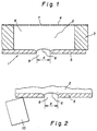
- FIG.. 1 shows a prior art cross sectional view of an inkjet print head 1.
- Orifices defining structures such as the depicted outlet plate 5 includes orifice 9 having a diameter "d" and can be manufactured by electro-forming or sheet metal fabrication methods. It will be understood that the outlet plate 5 actually includes a plurality of orifices for forming multiple ink droplets.
- the outlet plate 5 is glued to the piezo walls 3.
- Ink 2 is included in a pumping cavity 8.
- An inlet orifice 7 formed in a inlet plate 4 permits ink to be delivered to the pumping cavity 8.
- a meniscus 6 of ink is formed in the orifice 9.
- FIG. 2 shows the outlet plate 5 with the ink outlet meniscus 6 and a elastomeric wiper blade 10 in contact with the outlet orifice plate.
- the blade is in position to wipe across the diameter "d" of the orifice 9 to clean any ink or other particulate debris that could interfere with the proper functioning of the inkjet print head 1.
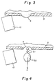
- FIG. 3 shows the meniscus 6 as it changes from an inward curve to an outward curve during the early stages before an actual ink droplet is manufactured.
- the elastomeric wiper blade 10 and the outlet orifice plate 5 are also shown.
- FIG. 4 shows the completed ink droplet 30, and its droplet direction is indicated by the arrow "X". Also shown are (as often is the case when an ink droplet is formed) two ink droplet satellites 31.
- the formation of satellites 31 is chaotic and can incorporate any number of ink droplet satellites 31 from 0 up to 10. These numbers of satellites 31 have been observed. Note that the outlet meniscus 6 has returned to the original state.
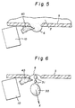
- FIG. 5 shows how debris40 can interfere with the meniscus 6 during the ink droplet formation.
- the droplet formation can be completely stopped by the ink surface condition change, due to the presence of the debris 40.
- outlet orifice plate 5 and elastomeric wiper blade 10 are shown for clarity.
- FIG.. 6 shows another defect caused by the presence of a debris 40.
- the direction of the droplet 30 with satellites 31 shown as "X" is changed and will result in a degradation of the image.
- outlet orifice plate 5 and elastomeric wiper blade 10 are shown for clarity. Note that the outlet meniscus 6 has returned to the original state but debris 40 can also interfere with that process.
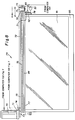
- FIG.. 7 shows an inkjet printing apparatus 79 in accordance with the present invention, an inkjet head 75, a drive motor 70 linked with a gearbox 71, an inkjet head belt drive wheel 74, and the inkjet head drive belt 72 to drive the inkjet head 75 back and for across the print paper 85.
- the inkjet droplets are controlled by the position of the inkjet head 75. This position is monitored by a position encoder strip 76 and the image input from computer 100.
- the same computer controls the inkjet print head 75, drive motor 70, the cleaning liquid 95, and the cleaning liquid pump 83.
- the cleaning liquid pump 83 pumps the cleaning liquid at a desired velocity towards the adjustable vane so that the vane creates a flow of cleaning liquid 95 past the outlet orifice plate 5.
- the inkjet generates an image 81(shown in FIG. 8) on the print paper 85.
- the print paper 85 is supported by the platen roller 78 and registration of the paper is controlled by the capstan roller 88. Both rollers, platen 78 and capstan 88 are driven by a motor not shown and are controlled by the computer 100.
- a cleaning station 89 which receives cleaning liquid 95.
- the cleaning station 89 has liquid pump 83 with inlet and outlet connections 50 and 51 to the cleaning liquid pump 83 .
- a mounting structure 87 supports all the associated mechanism for the inkjet printer 79.
- FIG. 8 shows the same printer as FIG. 7 but in a 90 degree rotated position. It can now be visualized how the inkjet head 75 with ink droplets 77 move across the paper 85 driven by the inkjet print head drive motor 70, a gearbox 71 to match motor speed with print speed.
- An inkjet head drive belt 72 driven by the belt drive wheel 74 drives the inkjet print head 75 across the total width of the print paper 85.
- the position of the print head 75 is metered by the position encoder strip 76.
- the encoder strip 76 At the right location determined by the computer 100 (shown in FIG. 7) and the encoder strip 76 a ink droplet 77 is deposited to form the image 81.
- the cleaning station 89 is mounted at the far right side end of the inkjet printer 79.
- the cleaning station 89 has a cleaning fluid tank 92, a cleaning liquid pump 83, with inlet connection 50 and an outlet connection 51.
- the adjustable vane 73 deflects the cleaning liquid 95 into a wave 52 is as shown. This wave 52 is used to clean the orifice plate 5.
- a number of different cleaning liquids can be used in accordance with the present invention.
- such fluids can include plain water, distilled water, and alcohol or detergent mixtures.
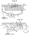
- FIG. 9 shows the cleaning liquid pump 83 with adjustable vane 73 mounted to a shaft 93 to rotate the adjustable vane 73.
- the vane is submerged in the cleaning liquid 95 and spaced from the outlet plate defining the orifices 9.
- the cleaning liquid 83 is pumped to flow across the adjustable vane 73, and occupies the cavity space 80 between the adjustable vane 73 and the outlet plate 5 so that a high enough fluid velocity is created to clean the orifices 9 and the outlet plate 5 from all debris 40.
- the adjustable vane 73 or the adjustable vane surface 53 is made from a material which conducive to laminar or turbulent flow of the cleaning liquid 95 through the cavity space 80.
- This adjustable vane 73 or vane surface material 53 can be selected from the group of materials consisting of aluminum, teflon, polyvinyl chlorine, stainless steel, glass, ceramic, and titanium.
- the friction of the cleaning liquid 95 on the on the outlet orifice plate 5 will cause a great amount of liquid shearing to remove dirt and ink from the outlet orifice plate 5.
- Arrows 101 indicates one of the possible two flow directions of the cleaning fluid.
- FIG. 10 shows in an enlarged form how the fluid friction shown by arrows 101 causes the flow of the cleaning liquid pump 83 to shear dirt and other debris 40 permanently from the outlet orifice plate 5.
- the arrows 101 indicate a laminar flow of fluid in the cleaning cavity space 80 but if desired a turbulent flow can be incorporated to enhance cleaning as desired.
- the adjustable vane 73 can be adjusted to squeeze the cavity dimension which will increases the flow at either end of the adjustable vane 73 to further help the cleaning effort. Also it is understood that the adjustable vane 73 can have many possible geometric shapes to facilitate the desired effects. Possible shapes are: cylinders, plates, foils, wedges, and ellipsoids.
Abstract
Description
- This invention generally relates to inkjet print head cleaning apparatus and more particularly relates to apparatus for cleaning orifices belonging to the inkjet print head.
- Many different types of digitally controlled printing systems of inkjet printing apparatus are presently being used. These inkjet printers use a variety of actuation mechanisms, a variety of marking materials, and a variety of recording media. For home applications, digital inkjet printing apparatus is the printing system of choice because low hardware cost make the printer affordable to every one. Another application for digital inkjet printing uses large format printers. It is a further requirement that these large format printers provide low cost copies with an ever improving quality. Inkjet printing technology is the first choice in today's art. Thus, there is a need for improved ways to make digitally controlled graphic arts media, such as billboards, large displays, and home photos for example, so that quality color images may be made at a high-speed and low cost, using standard or special paper.
- Inkjet printing has become recognized as a prominent contender in the digitally controlled, electronic printing arena because of its nonimpact, low-noise characteristics, its use of papers from plain paper to specialized high gloss papers and its avoidance of toner transfers and fixing. Inkjet printing mechanisms can be categorized as either continuous inkjet or droplet on demand inkjet. Continuous inkjet printing dates back to at least 1929. See U.S. Patent 1,941,001 to Hansell.
- U.S. Patent 3,373,437, issued to Sweet et al. in 1967, discloses an array of continuous inkjet orifices wherein ink droplets to be printed are selectively charged and deflected towards the recording medium. This technique is known as binary deflection continuous inkjet, and is used by several manufacturers, including Elmjet and Scitex.
- U.S. Patent 3,416,153, issued to Hertz et al. in 1966, discloses a method of achieving variable optical density of printed spots in continuous inkjet printing using the electrostatic dispersion of a charged droplet stream to modulate the number of droplets which pass trough a small orifice. This technique is used in inkjet printers manufactured by Iris.
- U.S. Patent 3,878,519, h issued to Eaton in 1974, discloses a method and apparatus for synchronizing droplet formation in a liquid stream using electrostatic deflection by a charging tunnel and deflection plates.
- US Patent 4,346,387, issued to Hertz in 1982 discloses a method and apparatus for controlling the electric charge on droplets formed by the breaking up of a pressurized liquid stream at a droplet formation point located within the electric field having an electric potential gradient. Droplet formation is effected at a point in the field corresponding to the desired predetermined charge to be placed on the droplets at the point of their formation. In addition to charging tunnels, deflection plates are used to actually deflect droplets.
- Conventional continuous inkjet utilizes electrostatic charging tunnels that are placed close to the point where the droplets are formed in a stream. In this manner individual droplets may be charged. The charged droplets may be deflected downstream by the presence of deflector plates that have a large potential difference between them. A gutter (sometimes referred to as a "catcher") may be used to intercept the charged droplets, while the uncharged droplets are free to strike the recording medium. If there is no electric field present or if the break off point from the droplet is sufficiently far from the electric field (even if a portion of the stream before droplets break off is in the presence of an electric field), then charging will not occur.
- The on demand type inkjet printers are covered by hundreds of patents and describe two techniques for droplet formation. At every orifice, (about 30 to 200 are used for a consumer type printer) a pressurization actuator is used to produce the inkjet droplet. The two types of actuators are heat and piezo materials. The heater at a convenient location heats ink and a quantity will phase change into a gaseous steam bubble and raise the internal ink pressure sufficiently for an ink droplet to be expelled to a suitable receiver. The piezo ink actuator incorporates a piezo material. It is said to possess piezo electric properties if an electric charge is produced when a mechanical stress is applied. This is commonly referred to as the "generator effect" "The converse also holds true; an applied electric field will produce a mechanical stress in the material. This is commonly referred to as the "motor effect". Some naturally occurring materials possessing this characteristics are: quartz and tourmaline. Some artificially produced piezoelectric crystals are: Rochelle salt, ammonium dihydrogen phosphate (ADP) and lithium sulphate (LH). The class of materials used for piezo actuators in an inkjet print head possessing those properties includes polarized piezoelectric ceramics. They are typically referred to as ferroelectric materials. In contrast to the naturally occurring piezoelectric crystals, ferroelectric ceramics are of the "polycrystalline" structure. The most commonly produced piezoelectric ceramics are: lead zirconate titanate, barium titanate, lead titanate, and lead metaniobate. For the inkjet print head a ferroelectric ceramic is machined to produce ink chambers. The chamber is water proofed by gold plating and becomes a conductor to apply the charge and cause the piezo "motor effect". This "motor effect" causes the ink cavity to shrink, raise the internal pressure, and generate an ink droplet.
- Inks for high speed jet droplet printers must have a number of special characteristics. Typically, water-based inks have been used because of their conductivity and viscosity range. Thus, for use in a jet droplet printer the ink must be electrically conductive, having a resistivity below about 5000 ohm-cm and preferably below about 500 ohm-cm. For good flow through small orifices water-based inks generally have a viscosity in the range between about 1 to 15 centipoise at 25 degree C.
- Over and above this, the ink must be stable over a long period of time, compatible with the materials comprising the orifice plate and ink manifold, free of living organisms, and functional after printing. The required functional characteristics after printing are: smear resistance after printing, fast drying on paper, and waterproof when dry. Examples of different types of water-based jet droplet printing inks are found in U.S. Patents 3,903,034; 3,889,269; 3,870,528; 3,846,141; 3,776,642; and 3,705,043.
- The ink also has to incorporate a nondrying characteristic in the jet cavity so that the drying of ink in the cavity is hindered or slowed to such a degree that through occasional spitting of ink droplets the cavities can be kept open. The addition of glycol will facilitate the free flow of ink through the inkjet. Inkjet printing apparatus typically includes an inkjet print head that is exposed to the various environment where inkjet printing is utilized. The orifices are exposed to all kinds of air born particles. Particulate debris accumulates on the surfaces, forming around the orifices. The ink will combine with such particulate debris to form an interference burr to block the orifice or cause through an altered surface wetting to inhibit a proper formation of the ink droplet. That particulate debris has to be cleaned from the orifice to restore proper droplet formation. This cleaning commonly is achieved by wiping, spraying, vacuum suction, and/or spitting of ink through the orifice. The wiping is the most common application.
- Inks used in inkjet printers can be said to have the following problems:
- 1) they require a large amount of energy to dry after printing;
- 2) large printed areas on paper usually cockle because of the amount of water present;
- 3) the printed images are sensitive to wet and dry rub;
- 4) the compositions of the ink usually require an anti-bacterial preservative to minimize the growth of bacteria in the ink;
- 5) the inks tend to dry out in and around the orifices resulting in clogging;
- 6) the wiping of the orifice plate causes wear on plate and wiper;
- 7) the wiper itself generates particles that clog the orifice;
- 8) cleaning cycles are time consuming and slow the productivity of inkjet printers. It is especially of concern in large format printers where frequent cleaning cycles interrupt the printing of an image; and
- 9) when a special printing pattern is initiated to compensate for plugged or badly performing orifices, the printing rate declines.
-
- Some of these problems may be overcome by the use of polar, conductive organic solvent based ink formulations. However, the use of non-polar organic solvents is generally precluded by their lack of electrical conductivity. The addition of solvent soluble salts can make such inks conductive, but such salts are often toxic, corrosive, and unstable.
- An object of the present invention to provide apparatus for cleaning orifices belonging to an inkjet print head.
- For use in an inkjet printer having an inkjet head and defining a structure having means including a structure defining a plurality of orifices for ejecting ink droplets, the invention resides in an inkjet print head cleaning apparatus, comprising:
- a) means defining an ink cleaning cavity spaced from the printing position for receiving cleaning fluid;
- b) an adjustable vane partially submerged in the cleaning fluid and spaced from the structure; and
- c) pumping means for delivering the cleaning liquid at a desired velocity towards the adjustable vane so that the vane creates a flow of cleaning liquid past the structure in the cleaning cavity space; and
- d) means for positioning the vane so as to create a desired flow of cleaning liquid which engages the structure such that the orifices are cleaned by the cleaning liquid.
-
- An advantage of the present invention is that rapid cleaning of print head orifices can be accomplished in a short time.
- Another advantage of the present invention is that as cleaning liquid is pumped over the surfaces of the adjustable vane is filtered and is replenished at a predetermined rate the cleaning liquid removes waste ink and particulate debris permanently from the inkjet print head.
- Yet another advantage of this invention is that the cleaning liquid flowing over the adjustable vane can have a substantial thickness thereby minimizing the requirements for mechanical tolerances.
- Still another advantage of this invention is that with no mechanical rubbing, wear of the delicate orifice plate is eliminated or greatly reduced. The replacement of the inkjet head will be less frequent and more of the orifices will stay functional to result in a higher image quality.
- Another advantage of this invention is that individual inks can be cleaned by selecting the pumping rate of fluid and angle of vane to change the laminar flow, and speed rate. In this way, the speed, quantity and direction of the fluid can be selected to match the cleaning needs of a particular ink. In other words, red , green, and blue inks in the same cartridge can have different roller speeds.
-
- FIG. 1 is a prior art cross sectional schematic view of a typical piezo electric inkjet print head;
- FIG. 2 is a schematic showing an ink droplet exit orifice in the FIG. 1 structure and an elastomeric wiper blade commonly used for cleaning the orifice plate;
- FIG. 3 the ink droplet as it begins to form in the orifice of FIG. 1;
- FIG. 4 shows the ink droplet after formation with the orifice of FIG.. 1;
- FIG. 5 shows the interference of the particulate debris with the formation of an ink droplet;
- FIG. 6 shows that a particulate material can cause a change of direction of ink droplets;
- FIG. 7 shows a schematic of inkjet printing apparatus in accordance with the present invention which shows a print head and a cleaning station;
- FIG. 8 shows the same as FIG. 7 but a different perspective for clarification of illustration;
- FIG. 9 shows the cleaning mechanism in accordance with the present invention; and
- FIG. 10 shows an enlargement of the cleaning liquid flowing across the adjustable vane surface.
-
- FIG.. 1 shows a prior art cross sectional view of an inkjet print head 1. Orifices defining structures such as the depicted
outlet plate 5 includesorifice 9 having a diameter "d" and can be manufactured by electro-forming or sheet metal fabrication methods. It will be understood that theoutlet plate 5 actually includes a plurality of orifices for forming multiple ink droplets. Theoutlet plate 5 is glued to thepiezo walls 3.Ink 2 is included in apumping cavity 8. Aninlet orifice 7 formed in a inlet plate 4 permits ink to be delivered to thepumping cavity 8. Ameniscus 6 of ink is formed in theorifice 9. - FIG. 2 shows the
outlet plate 5 with theink outlet meniscus 6 and aelastomeric wiper blade 10 in contact with the outlet orifice plate. The blade is in position to wipe across the diameter "d" of theorifice 9 to clean any ink or other particulate debris that could interfere with the proper functioning of the inkjet print head 1. - FIG. 3 shows the
meniscus 6 as it changes from an inward curve to an outward curve during the early stages before an actual ink droplet is manufactured. For reference and clarity theelastomeric wiper blade 10 and theoutlet orifice plate 5 are also shown. - FIG. 4 shows the completed
ink droplet 30, and its droplet direction is indicated by the arrow "X". Also shown are (as often is the case when an ink droplet is formed) twoink droplet satellites 31. The formation ofsatellites 31 is chaotic and can incorporate any number ofink droplet satellites 31 from 0 up to 10. These numbers ofsatellites 31 have been observed. Note that theoutlet meniscus 6 has returned to the original state. - FIG. 5 shows how debris40 can interfere with the
meniscus 6 during the ink droplet formation. As theink 2 touches thedebris 40, the droplet formation can be completely stopped by the ink surface condition change, due to the presence of thedebris 40. Againoutlet orifice plate 5 andelastomeric wiper blade 10 are shown for clarity. - FIG.. 6 shows another defect caused by the presence of a
debris 40. The direction of thedroplet 30 withsatellites 31 shown as "X" is changed and will result in a degradation of the image. Againoutlet orifice plate 5 andelastomeric wiper blade 10 are shown for clarity. Note that theoutlet meniscus 6 has returned to the original state butdebris 40 can also interfere with that process. - FIG.. 7 shows an
inkjet printing apparatus 79 in accordance with the present invention, aninkjet head 75, adrive motor 70 linked with agearbox 71, an inkjet headbelt drive wheel 74, and the inkjethead drive belt 72 to drive theinkjet head 75 back and for across theprint paper 85. The inkjet droplets are controlled by the position of theinkjet head 75. This position is monitored by aposition encoder strip 76 and the image input fromcomputer 100. The same computer controls theinkjet print head 75, drivemotor 70, the cleaningliquid 95, and the cleaningliquid pump 83. The cleaningliquid pump 83 pumps the cleaning liquid at a desired velocity towards the adjustable vane so that the vane creates a flow of cleaningliquid 95 past theoutlet orifice plate 5. Also shown are theguide 84 for straight line back and forth motion of theinkjet head 75. The inkjet generates an image 81(shown in FIG. 8) on theprint paper 85. Theprint paper 85 is supported by theplaten roller 78 and registration of the paper is controlled by thecapstan roller 88. Both rollers,platen 78 andcapstan 88 are driven by a motor not shown and are controlled by thecomputer 100. Also shown is a cleaningstation 89 which receives cleaningliquid 95. The cleaningstation 89 hasliquid pump 83 with inlet andoutlet connections liquid pump 83 . A mountingstructure 87 supports all the associated mechanism for theinkjet printer 79. - FIG. 8 shows the same printer as FIG. 7 but in a 90 degree rotated position. It can now be visualized how the
inkjet head 75 withink droplets 77 move across thepaper 85 driven by the inkjet printhead drive motor 70, agearbox 71 to match motor speed with print speed. An inkjethead drive belt 72 driven by thebelt drive wheel 74 drives theinkjet print head 75 across the total width of theprint paper 85. The position of theprint head 75 is metered by theposition encoder strip 76. At the right location determined by the computer 100 (shown in FIG. 7) and the encoder strip 76 aink droplet 77 is deposited to form theimage 81. When theinkjet print head 75 reaches the far end of theprint paper 85 it decelerates in the indicated direction and distance of arrow "d". When reversing' indicated by the direction and distance of arrow "a", theprint head 75 reaccelerates to the correct print speed. This turn around deceleration ("d") and re acceleration ("a") time is used to accomplish the cleaning without added time for theinkjet print head 75. The cleaningstation 89 is mounted at the far right side end of theinkjet printer 79. The cleaningstation 89 has a cleaningfluid tank 92, a cleaningliquid pump 83, withinlet connection 50 and anoutlet connection 51. Theadjustable vane 73 deflects the cleaningliquid 95 into awave 52 is as shown. Thiswave 52 is used to clean theorifice plate 5. A number of different cleaning liquids can be used in accordance with the present invention. For example, such fluids can include plain water, distilled water, and alcohol or detergent mixtures. - FIG. 9 shows the cleaning
liquid pump 83 withadjustable vane 73 mounted to ashaft 93 to rotate theadjustable vane 73. The vane is submerged in the cleaningliquid 95 and spaced from the outlet plate defining theorifices 9. The cleaningliquid 83 is pumped to flow across theadjustable vane 73, and occupies thecavity space 80 between theadjustable vane 73 and theoutlet plate 5 so that a high enough fluid velocity is created to clean theorifices 9 and theoutlet plate 5 from alldebris 40. Theadjustable vane 73 or theadjustable vane surface 53 is made from a material which conducive to laminar or turbulent flow of the cleaningliquid 95 through thecavity space 80. Thisadjustable vane 73 orvane surface material 53 can be selected from the group of materials consisting of aluminum, teflon, polyvinyl chlorine, stainless steel, glass, ceramic, and titanium. The friction of the cleaningliquid 95 on the on theoutlet orifice plate 5 will cause a great amount of liquid shearing to remove dirt and ink from theoutlet orifice plate 5.Arrows 101 indicates one of the possible two flow directions of the cleaning fluid. - FIG. 10 shows in an enlarged form how the fluid friction shown by
arrows 101 causes the flow of the cleaningliquid pump 83 to shear dirt andother debris 40 permanently from theoutlet orifice plate 5. Thearrows 101 indicate a laminar flow of fluid in thecleaning cavity space 80 but if desired a turbulent flow can be incorporated to enhance cleaning as desired. Theadjustable vane 73 can be adjusted to squeeze the cavity dimension which will increases the flow at either end of theadjustable vane 73 to further help the cleaning effort. Also it is understood that theadjustable vane 73 can have many possible geometric shapes to facilitate the desired effects. Possible shapes are: cylinders, plates, foils, wedges, and ellipsoids. When theoutlet plate 5 of the inkjet print head 75( see FIG. 8) moves across thecavity space 80 all parts of the outlet plate are exposed to low pressure and a high pressure caused by the angle of the adjustable vane. By positioning theadjustable vane 73, a laminar flow of cleaning liquid can be provided between theplate 5 and the surface of the vane. When in its counterclockwise position (angle "d" see FIG. 9 ), the flow rate is increased, creating a low pressure side as shown by the high concentration ofarrows 101. A high pressure side is shown by the low concentration ofarrows 101.
Claims (3)
- For use in an inkjet printer having an inkjet print head (1) defining a plurality of orifices (9) for ejecting ink droplets (30), an inkjet print head cleaning apparatus, comprising:a) a body defining an ink cleaning cavity (8) spaced from a printing position for receiving cleaning fluid;b) an adjustable vane (53) partially submerged in the cleaning fluid and spaced from the print head; andc) a pump (83) associated with the body for delivering the cleaning liquid at a predetermined velocity towards the adjustable vane so that the vane creates a flow of cleaning liquid past the structure in the cleaning cavity; andd) means for positioning the vane so as to create a desired flow of cleaning liquid which engages the print head such that the orifices are cleaned by the cleaning liquid.
- The inkjet printer of claim 1 wherein the vane is capable of being positioned so as to produce a high pressure side and a low pressure side with respect to the cleaning cavity.
- The inkjet printer of claim 2 wherein the vane is made from a material wetable by the cleaning liquid to enhance lamina flow of the cleaning liquid in the cleaning cavity.
Applications Claiming Priority (2)
| Application Number | Priority Date | Filing Date | Title |
|---|---|---|---|
| US159979 | 1998-09-24 | ||
| US09/159,979 US5997127A (en) | 1998-09-24 | 1998-09-24 | Adjustable vane used in cleaning orifices in inkjet printing apparatus |
Publications (2)
| Publication Number | Publication Date |
|---|---|
| EP0988976A2 true EP0988976A2 (en) | 2000-03-29 |
| EP0988976A3 EP0988976A3 (en) | 2000-05-24 |
Family
ID=22574951
Family Applications (1)
| Application Number | Title | Priority Date | Filing Date |
|---|---|---|---|
| EP99202977A Withdrawn EP0988976A3 (en) | 1998-09-24 | 1999-09-13 | Adjustable vane used in cleaning orifices in inkjet printing apparatus |
Country Status (3)
| Country | Link |
|---|---|
| US (1) | US5997127A (en) |
| EP (1) | EP0988976A3 (en) |
| JP (1) | JP2000094704A (en) |
Families Citing this family (15)
| Publication number | Priority date | Publication date | Assignee | Title |
|---|---|---|---|---|
| US6281909B1 (en) | 1998-09-24 | 2001-08-28 | Eastman Kodak Company | Cleaning orifices in ink jet printing apparatus |
| US6224185B1 (en) * | 1998-10-09 | 2001-05-01 | Eastman Kodak Company | Cleaning fluid for inkjet printers |
| US6350007B1 (en) | 1998-10-19 | 2002-02-26 | Eastman Kodak Company | Self-cleaning ink jet printer using ultrasonics and method of assembling same |
| US6145952A (en) * | 1998-10-19 | 2000-11-14 | Eastman Kodak Company | Self-cleaning ink jet printer and method of assembling same |
| US6286929B1 (en) * | 1998-12-29 | 2001-09-11 | Eastman Kodak Company | Self-cleaning ink jet printer with oscillating septum and ultrasonics and method of assembling the printer |
| US6183058B1 (en) * | 1999-09-28 | 2001-02-06 | Eastman Kodak Company | Self-cleaning ink jet printer system with reverse fluid flow and method of assembling the printer system |
| JP2002019132A (en) * | 2000-07-07 | 2002-01-23 | Mimaki Engineering Co Ltd | Mechanism and method for cleaning ink jet head of plotter |
| US6513903B2 (en) | 2000-12-29 | 2003-02-04 | Eastman Kodak Company | Ink jet print head with capillary flow cleaning |
| US6572215B2 (en) | 2001-05-30 | 2003-06-03 | Eastman Kodak Company | Ink jet print head with cross-flow cleaning |
| US6905552B2 (en) * | 2001-12-26 | 2005-06-14 | Xerox Corporation | Contactless cleaning of vertical ink jet printheads |
| JP5150129B2 (en) | 2007-04-20 | 2013-02-20 | 株式会社ミマキエンジニアリング | Printer device |
| US9260973B2 (en) | 2012-12-31 | 2016-02-16 | United Technologies Corporation | Fan blade adjustment piezoelectric actuator |
| DE102017109020B3 (en) | 2017-04-27 | 2018-10-18 | Océ Holding B.V. | Cleaning unit and method for cleaning a printhead |
| JP7206653B2 (en) * | 2018-07-05 | 2023-01-18 | コニカミノルタ株式会社 | Head cleaning device, image forming apparatus, and head cleaning method for image forming apparatus |
| CN110126479A (en) * | 2019-05-29 | 2019-08-16 | 王改 | A kind of drum-type ink jet numbering machine |
Citations (2)
| Publication number | Priority date | Publication date | Assignee | Title |
|---|---|---|---|---|
| US5412411A (en) * | 1993-11-26 | 1995-05-02 | Xerox Corporation | Capping station for an ink-jet printer with immersion of printhead in ink |
| US5559536A (en) * | 1987-03-31 | 1996-09-24 | Canon Kabushiki Kaisha | Recovery device having a protruding portion providing reduced pressure for improved recovery and method using same |
Family Cites Families (16)
| Publication number | Priority date | Publication date | Assignee | Title |
|---|---|---|---|---|
| US3373437A (en) * | 1964-03-25 | 1968-03-12 | Richard G. Sweet | Fluid droplet recorder with a plurality of jets |
| GB1143079A (en) * | 1965-10-08 | 1969-02-19 | Hertz Carl H | Improvements in or relating to recording devices for converting electrical signals |
| US3846141A (en) * | 1970-12-07 | 1974-11-05 | Dick Co Ab | Jet printing ink composition |
| US3903034A (en) * | 1970-12-07 | 1975-09-02 | Dick Co Ab | Offset jet printing ink |
| US3705043A (en) * | 1970-12-07 | 1972-12-05 | Dick Co Ab | Infrared absorptive jet printing ink composition |
| US3776642A (en) * | 1972-08-01 | 1973-12-04 | Dickey John Corp | Grain analysis computer |
| DE2258835A1 (en) * | 1972-12-01 | 1974-06-12 | Agfa Gevaert Ag | Aqueous INK FOR THE INK JET PROCESS |
| US3870528A (en) * | 1973-12-17 | 1975-03-11 | Ibm | Infrared and visible dual dye jet printer ink |
| US3878519A (en) * | 1974-01-31 | 1975-04-15 | Ibm | Method and apparatus for synchronizing droplet formation in a liquid stream |
| CA1158706A (en) * | 1979-12-07 | 1983-12-13 | Carl H. Hertz | Method and apparatus for controlling the electric charge on droplets and ink jet recorder incorporating the same |
| US5305015A (en) * | 1990-08-16 | 1994-04-19 | Hewlett-Packard Company | Laser ablated nozzle member for inkjet printhead |
| JP3175366B2 (en) * | 1992-12-01 | 2001-06-11 | 富士ゼロックス株式会社 | Inkjet recording ink |
| US5350616A (en) * | 1993-06-16 | 1994-09-27 | Hewlett-Packard Company | Composite orifice plate for ink jet printer and method for the manufacture thereof |
| US5426458A (en) * | 1993-08-09 | 1995-06-20 | Hewlett-Packard Corporation | Poly-p-xylylene films as an orifice plate coating |
| US5738716A (en) * | 1996-08-20 | 1998-04-14 | Eastman Kodak Company | Color pigmented ink jet ink set |
| US5725647A (en) * | 1996-11-27 | 1998-03-10 | Minnesota Mining And Manufacturing Company | Pigmented inks and humectants used therewith |
-
1998
- 1998-09-24 US US09/159,979 patent/US5997127A/en not_active Expired - Fee Related
-
1999
- 1999-09-13 EP EP99202977A patent/EP0988976A3/en not_active Withdrawn
- 1999-09-24 JP JP11270253A patent/JP2000094704A/en active Pending
Patent Citations (2)
| Publication number | Priority date | Publication date | Assignee | Title |
|---|---|---|---|---|
| US5559536A (en) * | 1987-03-31 | 1996-09-24 | Canon Kabushiki Kaisha | Recovery device having a protruding portion providing reduced pressure for improved recovery and method using same |
| US5412411A (en) * | 1993-11-26 | 1995-05-02 | Xerox Corporation | Capping station for an ink-jet printer with immersion of printhead in ink |
Also Published As
| Publication number | Publication date |
|---|---|
| JP2000094704A (en) | 2000-04-04 |
| EP0988976A3 (en) | 2000-05-24 |
| US5997127A (en) | 1999-12-07 |
Similar Documents
| Publication | Publication Date | Title |
|---|---|---|
| EP0988978B1 (en) | Cleaning of orifices in an ink jet printing apparatus | |
| US5997127A (en) | Adjustable vane used in cleaning orifices in inkjet printing apparatus | |
| EP1060894B1 (en) | Multi-fluidic cleaning for ink jet print heads | |
| US6513903B2 (en) | Ink jet print head with capillary flow cleaning | |
| US6350007B1 (en) | Self-cleaning ink jet printer using ultrasonics and method of assembling same | |
| EP1005997B1 (en) | A self-cleaning ink jet printer with reverse flow and method of assembling the printer | |
| EP1088664B1 (en) | A self-cleaning ink jet printer system with a reversible fluid flow and a method of assembling the printer system | |
| EP1052099A1 (en) | Self-cleaning ink printing printer with gutter cleaning structure and method of assembling the printer | |
| EP1016529A1 (en) | An ink jet printer with cleaning mechanism having a wiper blade and transducer and method of assembling the printer | |
| EP0992355A2 (en) | Cleaning and repairing fluid for printhead cleaning | |
| US10730305B2 (en) | Inkjet printing system with non-contact cleaning station | |
| EP0995602B1 (en) | A self-cleaning ink jet printer and method of assembling same | |
| US6497472B2 (en) | Self-cleaning ink jet printer and print head with cleaning fluid flow system | |
| EP1016531B1 (en) | A self-cleaning ink jet printer with oscillating septum and method of operating the printer | |
| EP1016530B1 (en) | A self-cleaning ink jet printer with oscillating septum and method of assembling the printer | |
| US6511155B1 (en) | Cleaning ink jet printheads and orifices | |
| CN101585261B (en) | Liquid-drop ejecting head, liquid-drop ejecting apparatus and image forming apparatus | |
| EP1170130A1 (en) | Method and cleaning assembly for cleaning an ink jet print head in a self-cleaning ink jet printer system | |
| US6047715A (en) | Turbulent cleaning action for ink jet print heads and orifices | |
| US6367905B1 (en) | Print head cleaning assembly with roller and method for an ink jet print head with fixed gutter | |
| US6905552B2 (en) | Contactless cleaning of vertical ink jet printheads | |
| EP0992354A2 (en) | Cleaning fluid for inkjet printers | |
| JP2004066571A (en) | Liquid drop ejecting head, ink cartridge, and image recorder | |
| JP3048022B2 (en) | Ink jet recording device | |
| JPH04176652A (en) | Ink jet recording device |
Legal Events
| Date | Code | Title | Description |
|---|---|---|---|
| PUAI | Public reference made under article 153(3) epc to a published international application that has entered the european phase |
Free format text: ORIGINAL CODE: 0009012 |
|
| AK | Designated contracting states |
Kind code of ref document: A2 Designated state(s): DE FR GB |
|
| AX | Request for extension of the european patent |
Free format text: AL;LT;LV;MK;RO;SI |
|
| PUAL | Search report despatched |
Free format text: ORIGINAL CODE: 0009013 |
|
| AK | Designated contracting states |
Kind code of ref document: A3 Designated state(s): AT BE CH CY DE DK ES FI FR GB GR IE IT LI LU MC NL PT SE |
|
| AX | Request for extension of the european patent |
Free format text: AL;LT;LV;MK;RO;SI |
|
| 17P | Request for examination filed |
Effective date: 20001109 |
|
| AKX | Designation fees paid |
Free format text: DE FR GB |
|
| STAA | Information on the status of an ep patent application or granted ep patent |
Free format text: STATUS: THE APPLICATION HAS BEEN WITHDRAWN |
|
| 18W | Application withdrawn |
Effective date: 20051024 |