EP0987986B1 - Surgical instrument - Google Patents
Surgical instrument Download PDFInfo
- Publication number
- EP0987986B1 EP0987986B1 EP98919816A EP98919816A EP0987986B1 EP 0987986 B1 EP0987986 B1 EP 0987986B1 EP 98919816 A EP98919816 A EP 98919816A EP 98919816 A EP98919816 A EP 98919816A EP 0987986 B1 EP0987986 B1 EP 0987986B1
- Authority
- EP
- European Patent Office
- Prior art keywords
- stem section
- extension spring
- vertebrae
- surgical tool
- spring
- Prior art date
- Legal status (The legal status is an assumption and is not a legal conclusion. Google has not performed a legal analysis and makes no representation as to the accuracy of the status listed.)
- Expired - Lifetime
Links
- 238000005452 bending Methods 0.000 claims description 9
- 239000002184 metal Substances 0.000 description 3
- 230000000712 assembly Effects 0.000 description 2
- 238000000429 assembly Methods 0.000 description 2
- 239000000463 material Substances 0.000 description 2
- 238000010276 construction Methods 0.000 description 1
- 230000000694 effects Effects 0.000 description 1
- 230000002093 peripheral effect Effects 0.000 description 1
- 229910001220 stainless steel Inorganic materials 0.000 description 1
- 239000010935 stainless steel Substances 0.000 description 1
Images

Classifications
-
- A—HUMAN NECESSITIES
- A61—MEDICAL OR VETERINARY SCIENCE; HYGIENE
- A61B—DIAGNOSIS; SURGERY; IDENTIFICATION
- A61B17/00—Surgical instruments, devices or methods, e.g. tourniquets
- A61B17/28—Surgical forceps
- A61B17/29—Forceps for use in minimally invasive surgery
-
- A—HUMAN NECESSITIES
- A61—MEDICAL OR VETERINARY SCIENCE; HYGIENE
- A61B—DIAGNOSIS; SURGERY; IDENTIFICATION
- A61B17/00—Surgical instruments, devices or methods, e.g. tourniquets
- A61B17/00234—Surgical instruments, devices or methods, e.g. tourniquets for minimally invasive surgery
- A61B2017/00292—Surgical instruments, devices or methods, e.g. tourniquets for minimally invasive surgery mounted on or guided by flexible, e.g. catheter-like, means
- A61B2017/003—Steerable
- A61B2017/00305—Constructional details of the flexible means
- A61B2017/00314—Separate linked members
-
- A—HUMAN NECESSITIES
- A61—MEDICAL OR VETERINARY SCIENCE; HYGIENE
- A61B—DIAGNOSIS; SURGERY; IDENTIFICATION
- A61B17/00—Surgical instruments, devices or methods, e.g. tourniquets
- A61B17/00234—Surgical instruments, devices or methods, e.g. tourniquets for minimally invasive surgery
- A61B2017/00292—Surgical instruments, devices or methods, e.g. tourniquets for minimally invasive surgery mounted on or guided by flexible, e.g. catheter-like, means
- A61B2017/003—Steerable
- A61B2017/00318—Steering mechanisms
- A61B2017/00323—Cables or rods
- A61B2017/00327—Cables or rods with actuating members moving in opposite directions
-
- A—HUMAN NECESSITIES
- A61—MEDICAL OR VETERINARY SCIENCE; HYGIENE
- A61B—DIAGNOSIS; SURGERY; IDENTIFICATION
- A61B17/00—Surgical instruments, devices or methods, e.g. tourniquets
- A61B17/28—Surgical forceps
- A61B17/29—Forceps for use in minimally invasive surgery
- A61B2017/2901—Details of shaft
- A61B2017/2905—Details of shaft flexible
-
- A—HUMAN NECESSITIES
- A61—MEDICAL OR VETERINARY SCIENCE; HYGIENE
- A61B—DIAGNOSIS; SURGERY; IDENTIFICATION
- A61B17/00—Surgical instruments, devices or methods, e.g. tourniquets
- A61B17/28—Surgical forceps
- A61B17/29—Forceps for use in minimally invasive surgery
- A61B2017/2901—Details of shaft
- A61B2017/2908—Multiple segments connected by articulations
Definitions
- the present invention relates to a surgical instrument and, more particularly, to an endoscopic surgical instrument which may be used for cutting and/or removal of tissue.
- the present invention is a surgical instrument according to claims 1 to 9 including a handle, a rigid stem section extending from the handle, and a flexible stem section extending from the rigid stem section.
- a surgical tool connected with a distal end of the flexible stem section includes a movable part.
- the flexible stem section comprises a plurality of relatively pivotable vertebrae extending along the flexible stem section, and an extension spring extending axially through the plurality of vertebrae for transmitting axial load between the surgical tool and the rigid stem section.
- An actuator cable extends through the extension spring and is connected with the movable tool part for applying force to the movable tool part to move the movable tool part relative to the flexible stem section.
- a surgical instrument comprising a handle, a rigid stem section, extending from said handle, a flexible stem section extending form said rigid stem section, a surgical tool connected with a distal end of said flexible stem section, said tool including a movable part, said stem section comprising a plurality of relatively pivotable vertebrae extending along said flexible stem section and an extension spring extending axially through said plurality of vertebrae, said spring extending from said rigid stem section to said surgical tool, whereby the proximal most vertebrae is pivotally connected with the rigid stem section and the distal most vertebrae is pivotally connected with the fixed part of the surgical tool and an actuation cable extends through the central passage in the movable stem section, the vertebrae being supported on each other.
- the present invention relates to a surgical instrument according to claims 1 to 9 and it particular to an endoscopic surgical instrument which may be used for cutting and/or removal of tissue.
- the present invention is applicable to various surgical instrument constructions.
- Fig. 1 illustrates a surgical instrument 10.
- the surgical instrument 10 includes generally a handle 12 with an actuator assembly 14 and a deflection control assembly 16.
- a proximal end portion 18 of a first stem section or rigid stem section 20 is fixed to the handle 12.
- a proximal end portion 22 of a second stem section or flexible stem section 24 is connected with a distal end portion 26 of the rigid stem section 20.
- the handle 12 ( Fig. 1 ) of the surgical instrument 10 has a pistol grip configuration which is configured to be manually gripped by a person's hand.
- the handle 12 includes a first handle part 40 and a second handle part 42 which in overall configuration are substantially mirror images of each other and which are joined together to form the handle.
- the second handle part 42 is, for clarity, shown only fragmentarily.
- the second handle part 42 overlies the first handle part 40 and covers the other parts of the surgical instrument 10 which are mounted on the first handle part.
- the first handle part 40 has an outer peripheral rim 44 extending around a main wall 46.
- a trigger pivot pin 48 projects from the inner side surface 50 of the main wall 46 of the first handle part 40.
- the trigger pivot pin 48 defines a trigger pivot axis 52.
- a deflection control lever pivot pin 54 projects from the inner side surface 50 of the main wall 46 of the first handle part 40, at a location spaced apart from the trigger pivot pin 48.
- the actuator assembly 14 includes a trigger 60.
- the trigger 60 is supported on the trigger pivot pin 48 for pivotal movement relative to the handle 12 about the pivot axis 52.
- the trigger 60 extends out of the handle 12 and is manually engageable to effect pivotal movement of the trigger relative to the handle.
- a generally V-shaped spring 64 formed as one piece with the trigger 60 engages a spring support pin 66 on the first handle part 40. The spring 64 biases the trigger 60 to an unactuated position, as shown in Fig. 1 , relative to the handle 12.
- the deflection control assembly 16 includes a deflection control lever 70.
- the deflection control lever 70 is supported on the deflection control lever pivot pin 54 for pivotal movement relative to the handle 12.
- a manually engageable portion 72 of the deflection control lever 70 projects from the handle 12.
- a tensioner 74 is disposed between the deflection control lever 70 and the first handle part 12.
- the tensioner 74 is supported for limited rotation about the pivot pin 54.
- deflection control assembly 16 is illustrated only schematically. Other types of deflection control assemblies can be substituted. Thus, the deflection control assembly 16 is illustrative of the various types of deflection control assemblies which can be used to provide the force for bending the flexible stem section 24 of the surgical instrument 10 in the manner illustrated.
- the rigid stem section 20 of the surgical instrument 10 includes a rigid main tube 80 which extends between and interconnects the handle 12 and the flexible stem section 24.
- the main tube 80 may be made from a suitable metal or plastic, as desired.
- the main tube 80 has a longitudinal central axis 82 ( Figs. 3 and 5 ) which forms a longitudinal central axis of the surgical instrument 10.
- a central passage 84 extends axially along the length of the main tube 80.
- a proximal end portion 86 ( Fig. 1 ) of the main tube 80 is fixed to the handle 12.
- the rigid stem section 20 includes an interface element 90 ( Fig. 5 ) fixed to a distal end portion 92 of the main tube 80.
- the interface element 90 has a disc-shaped main body portion 94.
- Upper and lower pairs of deflection control wire passages 100 and 102 extend axially through a radially outer section of the main body portion 94 of the interface element 90.
- a spring pocket 106 is formed in the main body portion 94 of the interface element 90.
- the spring pocket 106 has a cylindrical configuration centered on the axis 82.
- the spring pocket 106 faces distally, that is, in a direction away form the handle 12.
- a rib 108 is located on the distal end face 110 of the main body portion 94 of the interface element 90.
- the rib 108 is located between the two pairs of control wire passages 100 and 102.
- the rib 108 has a convex, semi-cylindrical cross sectional configuration extending into and out of the plane of the paper as viewed in Fig. 3 .
- the semi-cylindrical configuration of the rib 108 provides for bending or pivotal movement of the flexible stem section 24 relative to the rigid stem section 20, only in an upward or downward direction as viewed in Fig. 1-3 .
- a hollow tubular stem portion 112 of the interface element 90 extends proximally from the main body portion 94 of the interface element.
- the stem portion 112 of the interface element 90 extends inside the central passage 84 in the main tube 80.
- the flexible stem section 24 of the surgical instrument 10 includes a plurality of relatively pivotable vertebrae or links 120-129 arranged between the interface element 90 and the surgical tool 30.
- ten identical vertebrae 120-129 are provided.
- the number of vertebrae can differ, depending on the desired length and amount of bending movement of the flexible stem section 24.
- Each one of the vertebrae 120-129 has an annular, disc-shaped main body portion 130 ( Fig. 5 ) generally similar in configuration to the main body portion 94 of the interface element 90.
- a cylindrical spring passage 132 centered on the axis 82, extends axially through each one of the vertebrae 120-129.
- Upper and lower pairs of deflection control wire passages 134 and 136 extend axially through a radially outer section of the main body portion 94 of each vertebrae 120-129.
- each one of the links 120-129 has a convex, semi-cylindrical rib 138.
- the ribs 138 on the links 120-129 are identical in configuration and orientation to the rib 108 on the interface element 90.
- the spring passage 132 extends axially through the rib 138.
- the spring passage 132 widens as it extends distally from the main body portion 130 through the rib 138.
- each one of the links 120-129 has a concave, semi-cylindrical socket 140.
- Each one of the sockets 140 has a concave configuration adapted to pivotally receive one of the ribs 138.
- the links 120-129 are arranged relative to the rigid stem section 20 so that the socket 140 on the most proximal link 120 receives the rib 108 on the interface element 90.
- the rib 138 on the most proximal link 120 is received in the socket 140 on the next most proximal link 122.
- the ribs 138 on each one of the links 122-128 are received in the sockets 140 on the links 123-129, respectively.
- the rib 138 on the most distal link 129 is received in a socket 142 ( Fig. 5 ) on the fixed part 32 of the surgical tool 30.
- All the links 120-129 of the flexible stem section 24 are thus supported on the rigid stem section 20 for pivotal movement relative to the rigid stem section.
- the surgical tool 30 is supported on the flexible stem section 24 for pivotal movement relative to the flexible stem section and to the rigid stem section 20.
- the surgical tool 30, as viewed in Figs. 1-3 and 5 is movable in the plane of the paper.
- the fixed jaw 32 ( Fig. 3 ) of the surgical tool 30 has a support portion 160 and a cutting edge 162.
- a proximally facing spring pocket 154 is formed in the support portion 160 of the fixed jaw 32.
- a pivot pin 164 is mounted in the support portion 160 of the fixed jaw 32.
- the movable jaw 34 of the surgical tool 30 is supported on the pivot pin 164 for pivotal movement relative to the fixed jaw 32 about the pivot pin.
- the movable jaw 34 has a cutting edge 166 which is engageable with the cutting edge 162 of the fixed jaw 32 upon pivotal movement of the movable jaw from the open position shown in Fig. 5 to the closed position shown in Fig. 3 .
- the flexible stem section 24 includes an extension spring 150 for transmitting axial load between the surgical tool 30 and the rigid stem section 20 of the surgical instrument 10.
- the extension spring 150 is made from a suitable material, preferably stainless steel.
- the extension spring 150 is a coiled spring, specifically, a cylindrical helical spring, made from metal wire having a circular cross section. The extension spring 150 is in a free or unstressed condition when the flexible stem section 24 is in a linear condition as shown in Fig. 2 .
- the extension spring 150 When the extension spring 150 is in a free or unstressed condition, the coils of the spring are in abutting engagement along the length of the spring, and the spring is not compressible axially.
- a first end portion 152 ( Fig. 5 ) of the extension spring 150 is located in the spring pocket 154 in the fixed jaw 32 of the surgical tool 30.
- the extension spring 150 extends through the respective spring passages 132 in the stacked vertebrae 120-129, along the entire length of the flexible stem section 24.
- a second end portion 156 of the extension spring 150 is located in the spring pocket 106 in the interface element 90 of the rigid stem section 20.
- the surgical instrument 10 includes upper and lower deflection control wires 170 and 172 for controlling bending movement of the flexible stem section 24.
- Each one of the wires 170 and 172 is formed as a U-shaped loop having its ends connected to the deflection control lever 70 and its center looped around the fixed jaw 32 of the surgical tool 30.
- the proximal ends of the deflection control wires 170 and 172 are connected for movement with the deflection control lever 70.
- the deflection control wires 170 and 172 extend from the deflection control lever 70 over the tensioner 74 ( Fig. 1 ) and into the central passage 84 in the main tube 80.
- the tensioner 74 maintains an appropriate amount of tension on the deflection control wires 170 and 172.
- the deflection control wires 170 and 172 pass through the rigid stem section 20 into the interface element 90.
- the deflection control wires 170 and 172 extend through the control wire passages 100 and 102 in the interface element 90, and into the control wire passages 134 and 136 in the links 120-129 of the flexible stem section 24.
- Central portions 174 and 176 ( Fig. 3 ) of the deflection control wires 170 and 172 are looped around the support portion 160 of the fixed jaw 32 of the surgical tool 30.
- the surgical instrument 10 includes an actuator cable 180 for effecting pivotal movement of the movable jaw 34 relative to the fixed jaw 32.
- the actuator cable 180 is a flexible metal cable having a first end portion 182 ( Fig. 3 ) fixed to the movable jaw 34.
- the actuator cable 180 extends from the movable jaw 34 into the first end portion 152 of the extension spring 150.
- the actuator cable 180 extends for the entire length of the extension spring 150 and then into the stem portion 112 of the interface element 90.
- the dimensions of the extension spring 150 and the actuator cable 180 are selected so that the actuator cable is freely slidable axially within the extension spring but is constrained from radial movement within the extension spring. (The inner diameter of the extension spring 150 is exaggerated for clarity, in some of the Figures.)
- An actuator cable guide tube 184 is received in a recess 186 in the proximal end of the stem portion 112 of the interface element 90.
- the actuator cable guide tube 184 has a hollow, tubular configuration centered on the axis 82 and defining a cable passage 188.
- the actuator cable 180 extends from the extension spring 150 into the actuator cable guide tube 184.
- the inner diameter of the guide tube 184 is selected so that the actuator cable 180 is freely slidable axially within the passage 188 in the guide tube but is constrained from radial movement within the guide tube.
- a proximal end portion 190 ( Fig. 1 ) of the actuator cable guide tube 184 extends out of the proximal end portion 86 of the main tube 80 and is secured in the handle 12.
- the actuator cable 180 extends from the guide tube 184 and is secured to the trigger 60 in a manner not shown.
- the flexible stem section 24 of the surgical instrument 10 can be bent to a plurality of different orientations relative to the longitudinal axis 82.
- the rib 108 on the interface element 90 acts as a fulcrum about which the flexible stem section 24 of the surgical instrument 10 is bendable.
- the surgical instrument 10 bends because of tension on one or the other of the deflection control wires 170 and 172, when the deflection control lever 70 is moved.
- the end portions 174 and 176 of the deflection control wires 170 and 172 are connected with the deflection control lever 70 in a manner so that pivotal movement of the control lever in a first direction relative to the handle tensions the upper wire 170 and releases tension on the lower wire 172. Pivotal movement of the control lever 70 in a second direction, opposite to the first direction, releases tension on the upper wire 170 but tensions the lower wire 172.
- the amount of bending of the flexible stem section 24 of the surgical instrument 10 is controlled by the amount of tension on the deflection control wires 170 and 172. This is controlled by the amount of movement of the deflection control lever 70 relative to the handle 12. It should be understood that the present invention is not limited to bending movement of, for example, 90? or more. Thus, the flexible stem section 24 might be independently bendable at, say, 18° at each of ten different locations along its length, thus providing a total of 180° of bending movement.
- the surgical instrument 10 may be used in association with a cannula or other tubular member (not shown) which is used, in a known manner, to provide an open path through body tissue to an operating site. Once the cannula is properly positioned, the surgical instrument 10 is inserted axially through the cannula until at least the surgical tool 30 protrudes from the distal end of the cannula. A predetermined amount of the flexible stem section 24 of the surgical instrument 10 may also protrude from the distal end of the cannula.
- the flexible stem section 24 of the surgical instrument is bendable at about the location of the distal end of the cannula, to position the surgical tool 30 in the desired location.
- the distal end of the cannula acts as a fulcrum about which the flexible stem section 24 of the surgical instrument 10 bends.
- the surgical instrument bends through different arcuate paths of different lengths, at different locations along the length of the movable stem section 24.
- the actuator cable 180 When the trigger 60 is pulled, the actuator cable 180 is tensioned. The tensile force on the actuator cable 180 is transmitted into the movable jaw 34 and causes the movable jaw to pivot from the open position shown in Fig. 2 to the closed position shown in Fig. 3 .
- the movable jaw 34 moves relative to the fixed jaw 32 and relative to the flexible stem section 24.
- the force transmitted by the actuator cable 180 places an axial load on the fixed jaw 32 of the surgical tool 30.
- the fixed jaw 32 and thus the surgical tool 30 as a whole, is urged in a direction toward the rigid stem section 20.
- This pulling force on the surgical tool 30 is transmitted through the fixed jaw 32 to the first end portion 152 of the extension spring 150.
- the axial force on the extension spring 150 holds the first end portion 152 of the extension spring in the spring pocket 154 in the fixed jaw 32.
- the first end portion 152 of the extension spring 150 is, effectively, fixed for movement with the fixed jaw 32.
- the axial compressive force on the extension spring 150 is transmitted through the second end portion 156 of the extension spring into the rigid stem section 20.
- the compressive force on the extension spring 150 holds the second end portion 156 of the extension spring in the spring pocket 158 in the interface element 90.
- the second end portion 156 of the extension spring 150 is, effectively, fixed for movement with the rigid stem section 20.
- the length of the extension spring 150 is selected so that the extension spring carries substantially all axial load between the surgical tool 30 and the rigid stem section 20.
- the only significant axial load on the vertebrae 120-129 comes from the force of the deflection control wires 170 and 172.
- the vertebrae 120-129 are supported on each other, but only lightly, so as to enable free banding movement of the flexible stem section 24 even when there is a large axial load being directed from the tool through the flexible stem section to the handle 12.
- the flexible stem section 24 can bend relatively freely.
- the links 120-129 can be made from a lighter and/or less expensive material.
Description
- The present invention relates to a surgical instrument and, more particularly, to an endoscopic surgical instrument which may be used for cutting and/or removal of tissue.
- The present invention is a surgical instrument according to claims 1 to 9 including a handle, a rigid stem section extending from the handle, and a flexible stem section extending from the rigid stem section. A surgical tool connected with a distal end of the flexible stem section includes a movable part. The flexible stem section comprises a plurality of relatively pivotable vertebrae extending along the flexible stem section, and an extension spring extending axially through the plurality of vertebrae for transmitting axial load between the surgical tool and the rigid stem section. An actuator cable extends through the extension spring and is connected with the movable tool part for applying force to the movable tool part to move the movable tool part relative to the flexible stem section.
- From the
US-Patent No. 5 618 294 a surgical instrument is known comprising a handle, a rigid stem section, extending from said handle, a flexible stem section extending form said rigid stem section, a surgical tool connected with a distal end of said flexible stem section, said tool including a movable part, said stem section comprising a plurality of relatively pivotable vertebrae extending along said flexible stem section and an extension spring extending axially through said plurality of vertebrae, said spring extending from said rigid stem section to said surgical tool, whereby the proximal most vertebrae is pivotally connected with the rigid stem section and the distal most vertebrae is pivotally connected with the fixed part of the surgical tool and an actuation cable extends through the central passage in the movable stem section, the vertebrae being supported on each other. - Further features of the present invention will become apparent to those skilled in the art to which the present invention relates from reading the following specification with reference to the accompanying drawings, in which:
-
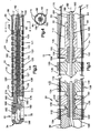
Fig. 1 is a side elevational view, with parts removed, of a surgical instrument constructed in accordance with a first embodiment of the present invention; -
Fig. 2 is an enlarged view of a flexible stem section of the surgical instrument ofFig. 1 , shown in a bent condition; -
Fig. 3 is an enlarged sectional view of the flexible stem section, shown in a linear condition; -
Fig. 4 is a view taken along line 4-4 ofFig. 3 ;
and -
Fig. 5 is a further enlarged view of portions ofFig. 3 . - The present invention relates to a surgical instrument according to claims 1 to 9 and it particular to an endoscopic surgical instrument which may be used for cutting and/or removal of tissue. The present invention is applicable to various surgical instrument constructions. As representative of the present invention,
Fig. 1 illustrates asurgical instrument 10. - The
surgical instrument 10 includes generally ahandle 12 with anactuator assembly 14 and adeflection control assembly 16. Aproximal end portion 18 of a first stem section orrigid stem section 20 is fixed to thehandle 12. Aproximal end portion 22 of a second stem section orflexible stem section 24 is connected with adistal end portion 26 of therigid stem section 20. Asurgical tool 30, including a fixed tool part 32 (Fig. 2 ) and amovable tool part 34, is located on a distal end portion ortip portion 36 of theflexible stem section 24. - The handle 12 (
Fig. 1 ) of thesurgical instrument 10 has a pistol grip configuration which is configured to be manually gripped by a person's hand. Thehandle 12 includes afirst handle part 40 and asecond handle part 42 which in overall configuration are substantially mirror images of each other and which are joined together to form the handle. Thesecond handle part 42 is, for clarity, shown only fragmentarily. Thesecond handle part 42, overlies thefirst handle part 40 and covers the other parts of thesurgical instrument 10 which are mounted on the first handle part. - The
first handle part 40 has an outerperipheral rim 44 extending around amain wall 46. A trigger pivot pin 48 projects from theinner side surface 50 of themain wall 46 of thefirst handle part 40. The trigger pivot pin 48 defines a trigger pivot axis 52. A deflection controllever pivot pin 54 projects from theinner side surface 50 of themain wall 46 of thefirst handle part 40, at a location spaced apart from the trigger pivot pin 48. - The
actuator assembly 14 includes atrigger 60. Thetrigger 60 is supported on the trigger pivot pin 48 for pivotal movement relative to thehandle 12 about the pivot axis 52. Thetrigger 60 extends out of thehandle 12 and is manually engageable to effect pivotal movement of the trigger relative to the handle. A generally V-shaped spring 64 formed as one piece with thetrigger 60 engages aspring support pin 66 on thefirst handle part 40. Thespring 64 biases thetrigger 60 to an unactuated position, as shown inFig. 1 , relative to thehandle 12. - The
deflection control assembly 16 includes adeflection control lever 70. Thedeflection control lever 70 is supported on the deflection controllever pivot pin 54 for pivotal movement relative to thehandle 12. A manuallyengageable portion 72 of the deflection control lever 70 projects from thehandle 12. - A
tensioner 74 is disposed between thedeflection control lever 70 and thefirst handle part 12. Thetensioner 74 is supported for limited rotation about thepivot pin 54. - It should be understood that the
deflection control assembly 16 is illustrated only schematically. Other types of deflection control assemblies can be substituted. Thus, thedeflection control assembly 16 is illustrative of the various types of deflection control assemblies which can be used to provide the force for bending theflexible stem section 24 of thesurgical instrument 10 in the manner illustrated. - The
rigid stem section 20 of thesurgical instrument 10 includes a rigidmain tube 80 which extends between and interconnects thehandle 12 and theflexible stem section 24. Themain tube 80 may be made from a suitable metal or plastic, as desired. Themain tube 80 has a longitudinal central axis 82 (Figs. 3 and 5 ) which forms a longitudinal central axis of thesurgical instrument 10. Acentral passage 84 extends axially along the length of themain tube 80. A proximal end portion 86 (Fig. 1 ) of themain tube 80 is fixed to thehandle 12. - The
rigid stem section 20 includes an interface element 90 (Fig. 5 ) fixed to adistal end portion 92 of themain tube 80. Theinterface element 90 has a disc-shapedmain body portion 94. Upper and lower pairs of deflectioncontrol wire passages 100 and 102 (only one of each pair is shown) extend axially through a radially outer section of themain body portion 94 of theinterface element 90. - A
spring pocket 106 is formed in themain body portion 94 of theinterface element 90. Thespring pocket 106 has a cylindrical configuration centered on theaxis 82. Thespring pocket 106 faces distally, that is, in a direction away form thehandle 12. - A
rib 108 is located on the distal end face 110 of themain body portion 94 of theinterface element 90. Therib 108 is located between the two pairs ofcontrol wire passages rib 108 has a convex, semi-cylindrical cross sectional configuration extending into and out of the plane of the paper as viewed inFig. 3 . The semi-cylindrical configuration of therib 108 provides for bending or pivotal movement of theflexible stem section 24 relative to therigid stem section 20, only in an upward or downward direction as viewed inFig. 1-3 . - A hollow
tubular stem portion 112 of theinterface element 90 extends proximally from themain body portion 94 of the interface element. Thestem portion 112 of theinterface element 90 extends inside thecentral passage 84 in themain tube 80. - The
flexible stem section 24 of thesurgical instrument 10 includes a plurality of relatively pivotable vertebrae or links 120-129 arranged between theinterface element 90 and thesurgical tool 30. In the illustrated embodiment, ten identical vertebrae 120-129 are provided. The number of vertebrae can differ, depending on the desired length and amount of bending movement of theflexible stem section 24. - Each one of the vertebrae 120-129 has an annular, disc-shaped main body portion 130 (
Fig. 5 ) generally similar in configuration to themain body portion 94 of theinterface element 90. Acylindrical spring passage 132, centered on theaxis 82, extends axially through each one of the vertebrae 120-129. Upper and lower pairs of deflectioncontrol wire passages 134 and 136 (only one of each pair is shown) extend axially through a radially outer section of themain body portion 94 of each vertebrae 120-129. - The distal end face of each one of the links 120-129 has a convex,
semi-cylindrical rib 138. Theribs 138 on the links 120-129 are identical in configuration and orientation to therib 108 on theinterface element 90. In each one of the links 120-129 thespring passage 132 extends axially through therib 138. Thespring passage 132 widens as it extends distally from themain body portion 130 through therib 138. - The proximal end face of each one of the links 120-129 has a concave,
semi-cylindrical socket 140. Each one of thesockets 140 has a concave configuration adapted to pivotally receive one of theribs 138. - The links 120-129 are arranged relative to the
rigid stem section 20 so that thesocket 140 on the mostproximal link 120 receives therib 108 on theinterface element 90. Therib 138 on the mostproximal link 120 is received in thesocket 140 on the next mostproximal link 122. In a similar manner, theribs 138 on each one of the links 122-128 are received in thesockets 140 on the links 123-129, respectively. Therib 138 on the mostdistal link 129 is received in a socket 142 (Fig. 5 ) on the fixedpart 32 of thesurgical tool 30. - All the links 120-129 of the
flexible stem section 24 are thus supported on therigid stem section 20 for pivotal movement relative to the rigid stem section. Thesurgical tool 30 is supported on theflexible stem section 24 for pivotal movement relative to the flexible stem section and to therigid stem section 20. Thesurgical tool 30, as viewed inFigs. 1-3 and5 , is movable in the plane of the paper. - The fixed jaw 32 (
Fig. 3 ) of thesurgical tool 30 has asupport portion 160 and acutting edge 162. A proximally facingspring pocket 154 is formed in thesupport portion 160 of the fixedjaw 32. Apivot pin 164 is mounted in thesupport portion 160 of the fixedjaw 32. - The
movable jaw 34 of thesurgical tool 30 is supported on thepivot pin 164 for pivotal movement relative to the fixedjaw 32 about the pivot pin. Themovable jaw 34 has acutting edge 166 which is engageable with thecutting edge 162 of the fixedjaw 32 upon pivotal movement of the movable jaw from the open position shown inFig. 5 to the closed position shown inFig. 3 . - The
flexible stem section 24 includes anextension spring 150 for transmitting axial load between thesurgical tool 30 and therigid stem section 20 of thesurgical instrument 10. Theextension spring 150 is made from a suitable material, preferably stainless steel. In the illustrated embodiment, theextension spring 150 is a coiled spring, specifically, a cylindrical helical spring, made from metal wire having a circular cross section. Theextension spring 150 is in a free or unstressed condition when theflexible stem section 24 is in a linear condition as shown inFig. 2 . - When the
extension spring 150 is in a free or unstressed condition, the coils of the spring are in abutting engagement along the length of the spring, and the spring is not compressible axially. - A first end portion 152 (
Fig. 5 ) of theextension spring 150 is located in thespring pocket 154 in the fixedjaw 32 of thesurgical tool 30. Theextension spring 150 extends through therespective spring passages 132 in the stacked vertebrae 120-129, along the entire length of theflexible stem section 24. Asecond end portion 156 of theextension spring 150 is located in thespring pocket 106 in theinterface element 90 of therigid stem section 20. - The
surgical instrument 10 includes upper and lowerdeflection control wires flexible stem section 24. Each one of thewires deflection control lever 70 and its center looped around the fixedjaw 32 of thesurgical tool 30. The proximal ends of thedeflection control wires deflection control lever 70. Thedeflection control wires deflection control lever 70 over the tensioner 74 (Fig. 1 ) and into thecentral passage 84 in themain tube 80. - The
tensioner 74 maintains an appropriate amount of tension on thedeflection control wires - The
deflection control wires rigid stem section 20 into theinterface element 90. Thedeflection control wires control wire passages interface element 90, and into thecontrol wire passages flexible stem section 24.Central portions 174 and 176 (Fig. 3 ) of thedeflection control wires support portion 160 of the fixedjaw 32 of thesurgical tool 30. - The
surgical instrument 10 includes anactuator cable 180 for effecting pivotal movement of themovable jaw 34 relative to the fixedjaw 32. Theactuator cable 180 is a flexible metal cable having a first end portion 182 (Fig. 3 ) fixed to themovable jaw 34. Theactuator cable 180 extends from themovable jaw 34 into thefirst end portion 152 of theextension spring 150. Theactuator cable 180 extends for the entire length of theextension spring 150 and then into thestem portion 112 of theinterface element 90. The dimensions of theextension spring 150 and theactuator cable 180 are selected so that the actuator cable is freely slidable axially within the extension spring but is constrained from radial movement within the extension spring. (The inner diameter of theextension spring 150 is exaggerated for clarity, in some of the Figures.) - An actuator
cable guide tube 184 is received in arecess 186 in the proximal end of thestem portion 112 of theinterface element 90. The actuatorcable guide tube 184 has a hollow, tubular configuration centered on theaxis 82 and defining acable passage 188. Theactuator cable 180 extends from theextension spring 150 into the actuatorcable guide tube 184. The inner diameter of theguide tube 184 is selected so that theactuator cable 180 is freely slidable axially within thepassage 188 in the guide tube but is constrained from radial movement within the guide tube. - A proximal end portion 190 (
Fig. 1 ) of the actuatorcable guide tube 184 extends out of theproximal end portion 86 of themain tube 80 and is secured in thehandle 12. Theactuator cable 180 extends from theguide tube 184 and is secured to thetrigger 60 in a manner not shown. - The
flexible stem section 24 of thesurgical instrument 10 can be bent to a plurality of different orientations relative to thelongitudinal axis 82. Therib 108 on theinterface element 90 acts as a fulcrum about which theflexible stem section 24 of thesurgical instrument 10 is bendable. Thesurgical instrument 10 bends because of tension on one or the other of thedeflection control wires deflection control lever 70 is moved. - The
end portions deflection control wires 170 and 172 (Fig. 1 ) are connected with thedeflection control lever 70 in a manner so that pivotal movement of the control lever in a first direction relative to the handle tensions theupper wire 170 and releases tension on thelower wire 172. Pivotal movement of thecontrol lever 70 in a second direction, opposite to the first direction, releases tension on theupper wire 170 but tensions thelower wire 172. - For example, movement of the manually engageable portion of the
deflection control lever 70 in a downward direction as viewed inFig. 1 results in tensioning of the upperdeflection control wire 170 and release of tension on thelower control wire 172. Theflexible stem section 24 of theInstrument 10 bends upward, as shown inFig. 2 . - Conversely, movement of the manually engageable portion of the
deflection control lever 70 in an upward direction (not shown) as viewed inFig. 1 results in tensioning of the lowerdeflection control wire 172 and release of tension on theupper control wire 170. Theflexible stem section 24 of theinstrument 10 bends downward. - The amount of bending of the
flexible stem section 24 of thesurgical instrument 10 is controlled by the amount of tension on thedeflection control wires deflection control lever 70 relative to thehandle 12. It should be understood that the present invention is not limited to bending movement of, for example, 90? or more. Thus, theflexible stem section 24 might be independently bendable at, say, 18° at each of ten different locations along its length, thus providing a total of 180° of bending movement. - The
surgical instrument 10 may be used in association with a cannula or other tubular member (not shown) which is used, in a known manner, to provide an open path through body tissue to an operating site. Once the cannula is properly positioned, thesurgical instrument 10 is inserted axially through the cannula until at least thesurgical tool 30 protrudes from the distal end of the cannula. A predetermined amount of theflexible stem section 24 of thesurgical instrument 10 may also protrude from the distal end of the cannula. - When the
surgical instrument 10 is thus inserted through the cannula, and thedeflection control lever 70 is moved, theflexible stem section 24 of the surgical instrument is bendable at about the location of the distal end of the cannula, to position thesurgical tool 30 in the desired location. The distal end of the cannula acts as a fulcrum about which theflexible stem section 24 of thesurgical instrument 10 bends. Depending on how much of thesurgical instrument 10 protrudes from the distal end of the cannula, the surgical instrument bends through different arcuate paths of different lengths, at different locations along the length of themovable stem section 24. - When the
trigger 60 is pulled, theactuator cable 180 is tensioned. The tensile force on theactuator cable 180 is transmitted into themovable jaw 34 and causes the movable jaw to pivot from the open position shown inFig. 2 to the closed position shown inFig. 3 . - The
movable jaw 34 moves relative to the fixedjaw 32 and relative to theflexible stem section 24. - The force transmitted by the
actuator cable 180 places an axial load on the fixedjaw 32 of thesurgical tool 30. The fixedjaw 32, and thus thesurgical tool 30 as a whole, is urged in a direction toward therigid stem section 20. This pulling force on thesurgical tool 30 is transmitted through the fixedjaw 32 to thefirst end portion 152 of theextension spring 150. The axial force on theextension spring 150 holds thefirst end portion 152 of the extension spring in thespring pocket 154 in the fixedjaw 32. Thefirst end portion 152 of theextension spring 150 is, effectively, fixed for movement with the fixedjaw 32. - The axial compressive force on the
extension spring 150 is transmitted through thesecond end portion 156 of the extension spring into therigid stem section 20. The compressive force on theextension spring 150 holds thesecond end portion 156 of the extension spring in thespring pocket 158 in theinterface element 90. Thesecond end portion 156 of theextension spring 150 is, effectively, fixed for movement with therigid stem section 20. - The length of the
extension spring 150 is selected so that the extension spring carries substantially all axial load between thesurgical tool 30 and therigid stem section 20. Thus, there is no substantial axial load transmitted through any of the vertebrae 120-129. The only significant axial load on the vertebrae 120-129 comes from the force of thedeflection control wires flexible stem section 24 even when there is a large axial load being directed from the tool through the flexible stem section to thehandle 12. As a result, theflexible stem section 24 can bend relatively freely. Also, the links 120-129 can be made from a lighter and/or less expensive material.
Claims (9)
- A surgical instrument comprising:a handle (12);a rigid stem section (20) extending from said handle (12);a flexible stem section (24) extending from said rigid stem section (20);a surgical tool (30) connected with a distal end of said flexible stem section (24), said surgical tool (30) Including a movable part (34) and a fixed part (32);said flexible stem section (24) comprising a plurality of relatively pivotable vertebrae (120-129) extending along said flexible stem section (24) and an extension spring (150) extending axially through said plurality of vertebrae (120-129), said extension spring (150) extending from said rigid stem section (20) to said surgical tool (30), whereby the proximal most (120) and distal most vertebrae (129) are respectively pivotally connected with the rigid stem section (20) and the fixed part (32) of the surgical tool (30), the proximal most vertebrae has a socket that pivotally connects said vertebrae with a rib extending distally from the rigid stem section, similar to the rib of the other vertebrae, Said extension spring (150) having a length which Is selected such that the extension spring (150) is configured for transmitting substantially all axial load between said surgical tool (30) and said rigid stem section (20), said vertebrae (120-129) being supported on each other so as to enable free bending movement of said flexible stem section (24) even when there is a large axial load being transmitted through said flexible stem sections (24) between said surgical tool (30) and said rigid stem section (20); andan actuator cable (180) extending through said extension spring (150) and connected with said movable tool part (34) for applying force to said movable tool part (34) to move said movable part (34) relative to said flexible stem section (24).
- An instrument as set forth in claim 1 wherein the dimensions of said extension spring (150) and said vertebrae (120-129) are selected so that substantially all axial compressive force from said surgical tool (30) to said rigid stem section (20) is transmitted through said extension spring (150) and not through said vertebrae (120-129).
- An instrument as set forth in claim 1 wherein said extension spring (150) is a coil spring having opposite first and second end portions (152, 156), said first end portion (152) of said extension spring (150) engaging said surgical tool (30) and said second end portion (156) of said extension spring (150) engaging said rigid stem section (20).
- An instrument as set forth in claim 3 wherein said first and second end portions (152, 156) of said spring (150) are received in respective spring pockets (154, 106) in said surgical tool (30) and said rigid stem section (20).
- An instrument as set forth in claim 1 comprising at least one deflection control wire (170, 172) for moving said flexible stem section (24) between a plurality of orientations relative to said rigid stem section (20), said wire (170, 172) extending through said vertebrae (120-129), said wire (170, 172) applying an axial load on said surgical tool (30) to urge said fixed tool part (32) toward said rigid stem section (20) thereby placing an axial compressive load on said extension spring (150).
- A surgical instrument as set forth in claim 5 wherein said actuator cable (180) and said extension spring (150) bend during movement of said flexible stem section (24) and said surgical tool (30) between said plurality of orientations.
- An instrument as set forth in claim 1 wherein said rigid stem section (20) has a curved surface for supporting said plurality of vertebrae (120-129) for bending movement relative to said rigid stem section (20).
- An instrument as set forth in claim 1 wherein said extension spring (150) is in a free or unstressed condition in which the coils of said spring (150) are in abutting engagement along the length of said spring (150) and said spring (150) is not compressible axially, when said flexible stem section (24) is in a linear condition.
- An instrument as set forth in claim 1 wherein said actuator cable (180) comprises a flexible member which extends for the entire length of said extension spring (150) and which is connected with a manually engageable member on said handle (12), said manually engageable member on said handle (12) being movable to transmit force through said actuator cable (180) for moving said movable tool part (34) relative to said flexible stem section (24).
Applications Claiming Priority (3)
| Application Number | Priority Date | Filing Date | Title |
|---|---|---|---|
| US08/873,283 US5938678A (en) | 1997-06-11 | 1997-06-11 | Surgical instrument |
| US873283 | 1997-06-11 | ||
| PCT/US1998/007962 WO1998056297A1 (en) | 1997-06-11 | 1998-04-21 | Surgical instrument |
Publications (3)
| Publication Number | Publication Date |
|---|---|
| EP0987986A1 EP0987986A1 (en) | 2000-03-29 |
| EP0987986A4 EP0987986A4 (en) | 2001-01-31 |
| EP0987986B1 true EP0987986B1 (en) | 2012-12-26 |
Family
ID=25361325
Family Applications (1)
| Application Number | Title | Priority Date | Filing Date |
|---|---|---|---|
| EP98919816A Expired - Lifetime EP0987986B1 (en) | 1997-06-11 | 1998-04-21 | Surgical instrument |
Country Status (5)
| Country | Link |
|---|---|
| US (1) | US5938678A (en) |
| EP (1) | EP0987986B1 (en) |
| JP (1) | JP2002503131A (en) |
| AU (1) | AU7252098A (en) |
| WO (1) | WO1998056297A1 (en) |
Families Citing this family (120)
| Publication number | Priority date | Publication date | Assignee | Title |
|---|---|---|---|---|
| US6436107B1 (en) * | 1996-02-20 | 2002-08-20 | Computer Motion, Inc. | Method and apparatus for performing minimally invasive surgical procedures |
| US6132441A (en) | 1996-11-22 | 2000-10-17 | Computer Motion, Inc. | Rigidly-linked articulating wrist with decoupled motion transmission |
| US6852107B2 (en) | 2002-01-16 | 2005-02-08 | Computer Motion, Inc. | Minimally invasive surgical training using robotics and tele-collaboration |
| US6398726B1 (en) | 1998-11-20 | 2002-06-04 | Intuitive Surgical, Inc. | Stabilizer for robotic beating-heart surgery |
| US6659939B2 (en) | 1998-11-20 | 2003-12-09 | Intuitive Surgical, Inc. | Cooperative minimally invasive telesurgical system |
| US8527094B2 (en) | 1998-11-20 | 2013-09-03 | Intuitive Surgical Operations, Inc. | Multi-user medical robotic system for collaboration or training in minimally invasive surgical procedures |
| US6464711B1 (en) | 1999-03-19 | 2002-10-15 | Medtronic Xomed, Inc. | Articulating mechanism for steerable surgical cutting instruments |
| US6424885B1 (en) * | 1999-04-07 | 2002-07-23 | Intuitive Surgical, Inc. | Camera referenced control in a minimally invasive surgical apparatus |
| US8944070B2 (en) | 1999-04-07 | 2015-02-03 | Intuitive Surgical Operations, Inc. | Non-force reflecting method for providing tool force information to a user of a telesurgical system |
| AU2002224519A1 (en) * | 2000-07-21 | 2002-02-05 | Atropos Limited | A surgical instrument |
| US6679886B2 (en) * | 2000-09-01 | 2004-01-20 | Synthes (Usa) | Tools and methods for creating cavities in bone |
| US6656195B2 (en) | 2000-09-22 | 2003-12-02 | Medtronic Xomed, Inc. | Flexible inner tubular members and rotary tissue cutting instruments having flexible inner tubular members |
| ATE495703T1 (en) | 2000-11-28 | 2011-02-15 | Intuitive Surgical Operations | ENDOSCOPIC STABILIZER FOR THE BEATING HEART AND VESSEL OCCLUSION OCCLUSION |
| US20030135204A1 (en) * | 2001-02-15 | 2003-07-17 | Endo Via Medical, Inc. | Robotically controlled medical instrument with a flexible section |
| US6817974B2 (en) | 2001-06-29 | 2004-11-16 | Intuitive Surgical, Inc. | Surgical tool having positively positionable tendon-actuated multi-disk wrist joint |
| US20060178556A1 (en) | 2001-06-29 | 2006-08-10 | Intuitive Surgical, Inc. | Articulate and swapable endoscope for a surgical robot |
| CA2792000C (en) | 2001-06-29 | 2016-08-16 | Intuitive Surgical, Inc. | Platform link wrist mechanism |
| EP2865351B1 (en) * | 2002-12-06 | 2018-11-28 | Intuitive Surgical Operations, Inc. | Flexible wrist for surgical tool |
| US7008375B2 (en) * | 2003-04-03 | 2006-03-07 | Surgical Solutions Llc | Articulating shaft |
| JP4791967B2 (en) | 2003-05-21 | 2011-10-12 | ザ・ジョンズ・ホプキンス・ユニバーシティー | Devices, systems and methods for minimally invasive surgery of mammalian throat and other parts of body |
| US8100824B2 (en) * | 2003-05-23 | 2012-01-24 | Intuitive Surgical Operations, Inc. | Tool with articulation lock |
| US8182417B2 (en) * | 2004-11-24 | 2012-05-22 | Intuitive Surgical Operations, Inc. | Articulating mechanism components and system for easy assembly and disassembly |
| US8562640B2 (en) * | 2007-04-16 | 2013-10-22 | Intuitive Surgical Operations, Inc. | Tool with multi-state ratcheted end effector |
| US7410483B2 (en) * | 2003-05-23 | 2008-08-12 | Novare Surgical Systems, Inc. | Hand-actuated device for remote manipulation of a grasping tool |
| US7090637B2 (en) * | 2003-05-23 | 2006-08-15 | Novare Surgical Systems, Inc. | Articulating mechanism for remote manipulation of a surgical or diagnostic tool |
| US7121781B2 (en) * | 2003-06-11 | 2006-10-17 | Intuitive Surgical | Surgical instrument with a universal wrist |
| US7147650B2 (en) * | 2003-10-30 | 2006-12-12 | Woojin Lee | Surgical instrument |
| US7338513B2 (en) | 2003-10-30 | 2008-03-04 | Cambridge Endoscopic Devices, Inc. | Surgical instrument |
| US7842028B2 (en) | 2005-04-14 | 2010-11-30 | Cambridge Endoscopic Devices, Inc. | Surgical instrument guide device |
| US7686826B2 (en) * | 2003-10-30 | 2010-03-30 | Cambridge Endoscopic Devices, Inc. | Surgical instrument |
| US8221424B2 (en) | 2004-12-20 | 2012-07-17 | Spinascope, Inc. | Surgical instrument for orthopedic surgery |
| US7585300B2 (en) * | 2003-12-19 | 2009-09-08 | Spinascope, Inc. | Dissecting high speed burr for spinal surgery |
| US8123757B2 (en) * | 2003-12-31 | 2012-02-28 | Depuy Spine, Inc. | Inserter instrument and implant clip |
| US7678117B2 (en) * | 2004-06-07 | 2010-03-16 | Novare Surgical Systems, Inc. | Articulating mechanism with flex-hinged links |
| US7828808B2 (en) * | 2004-06-07 | 2010-11-09 | Novare Surgical Systems, Inc. | Link systems and articulation mechanisms for remote manipulation of surgical or diagnostic tools |
| JP4976296B2 (en) * | 2004-08-31 | 2012-07-18 | サージカル ソリューションズ リミテッド ライアビリティ カンパニー | Medical device having a bent shaft |
| US7963976B2 (en) * | 2004-11-04 | 2011-06-21 | Dynamic Surgical Inventions, Llc | Articulated surgical probe and method for use |
| US7785252B2 (en) * | 2004-11-23 | 2010-08-31 | Novare Surgical Systems, Inc. | Articulating sheath for flexible instruments |
| US9700334B2 (en) * | 2004-11-23 | 2017-07-11 | Intuitive Surgical Operations, Inc. | Articulating mechanisms and link systems with torque transmission in remote manipulation of instruments and tools |
| US20060201130A1 (en) * | 2005-01-31 | 2006-09-14 | Danitz David J | Articulating mechanisms with joint assembly and manual handle for remote manipulation of instruments and tools |
| US9789608B2 (en) | 2006-06-29 | 2017-10-17 | Intuitive Surgical Operations, Inc. | Synthetic representation of a surgical robot |
| US8409175B2 (en) * | 2005-07-20 | 2013-04-02 | Woojin Lee | Surgical instrument guide device |
| US9271720B2 (en) * | 2005-08-11 | 2016-03-01 | Biomet Sports Medicine, Llc | Steerable suture passing device |
| US10702285B2 (en) | 2005-12-20 | 2020-07-07 | Quantum Medical Innovations, LLC | Method and apparatus for performing minimally invasive arthroscopic procedures |
| US8679097B2 (en) * | 2005-12-20 | 2014-03-25 | Orthodynamix Llc | Method and devices for minimally invasive arthroscopic procedures |
| EP1962665A4 (en) * | 2005-12-20 | 2010-02-17 | Orthodynamix Llc | Method and devices for minimally invasive arthroscopic procedures |
| US9962168B2 (en) | 2005-12-20 | 2018-05-08 | CroJor, LLC | Method and apparatus for performing minimally invasive arthroscopic procedures |
| US20070185519A1 (en) * | 2006-02-07 | 2007-08-09 | Hassler William L Jr | Articulating surgical instrument |
| US8105350B2 (en) * | 2006-05-23 | 2012-01-31 | Cambridge Endoscopic Devices, Inc. | Surgical instrument |
| US7615067B2 (en) | 2006-06-05 | 2009-11-10 | Cambridge Endoscopic Devices, Inc. | Surgical instrument |
| JP4731606B2 (en) | 2006-06-08 | 2011-07-27 | サージカル・ソルーシヨンズ・エルエルシー | Medical device having articulated shaft |
| US8062211B2 (en) | 2006-06-13 | 2011-11-22 | Intuitive Surgical Operations, Inc. | Retrograde instrument |
| US7862554B2 (en) | 2007-04-16 | 2011-01-04 | Intuitive Surgical Operations, Inc. | Articulating tool with improved tension member system |
| US8409244B2 (en) | 2007-04-16 | 2013-04-02 | Intuitive Surgical Operations, Inc. | Tool with end effector force limiter |
| US9561045B2 (en) * | 2006-06-13 | 2017-02-07 | Intuitive Surgical Operations, Inc. | Tool with rotation lock |
| US10008017B2 (en) | 2006-06-29 | 2018-06-26 | Intuitive Surgical Operations, Inc. | Rendering tool information as graphic overlays on displayed images of tools |
| US9718190B2 (en) | 2006-06-29 | 2017-08-01 | Intuitive Surgical Operations, Inc. | Tool position and identification indicator displayed in a boundary area of a computer display screen |
| US10258425B2 (en) | 2008-06-27 | 2019-04-16 | Intuitive Surgical Operations, Inc. | Medical robotic system providing an auxiliary view of articulatable instruments extending out of a distal end of an entry guide |
| US20090192523A1 (en) | 2006-06-29 | 2009-07-30 | Intuitive Surgical, Inc. | Synthetic representation of a surgical instrument |
| US8029531B2 (en) * | 2006-07-11 | 2011-10-04 | Cambridge Endoscopic Devices, Inc. | Surgical instrument |
| US7708758B2 (en) * | 2006-08-16 | 2010-05-04 | Cambridge Endoscopic Devices, Inc. | Surgical instrument |
| US7648519B2 (en) * | 2006-09-13 | 2010-01-19 | Cambridge Endoscopic Devices, Inc. | Surgical instrument |
| US7992338B2 (en) | 2006-09-25 | 2011-08-09 | Bowman Paul P | Finger alignment devices for triggers and trigger-activated devices incorporating the same |
| US8475453B2 (en) * | 2006-10-06 | 2013-07-02 | Covidien Lp | Endoscopic vessel sealer and divider having a flexible articulating shaft |
| US9237916B2 (en) * | 2006-12-15 | 2016-01-19 | Gmedeleware 2 Llc | Devices and methods for vertebrostenting |
| US20080262492A1 (en) * | 2007-04-11 | 2008-10-23 | Cambridge Endoscopic Devices, Inc. | Surgical Instrument |
| US8579910B2 (en) | 2007-05-18 | 2013-11-12 | DePuy Synthes Products, LLC | Insertion blade assembly and method of use |
| US8409245B2 (en) * | 2007-05-22 | 2013-04-02 | Woojin Lee | Surgical instrument |
| US9469034B2 (en) | 2007-06-13 | 2016-10-18 | Intuitive Surgical Operations, Inc. | Method and system for switching modes of a robotic system |
| US9138129B2 (en) | 2007-06-13 | 2015-09-22 | Intuitive Surgical Operations, Inc. | Method and system for moving a plurality of articulated instruments in tandem back towards an entry guide |
| US8620473B2 (en) | 2007-06-13 | 2013-12-31 | Intuitive Surgical Operations, Inc. | Medical robotic system with coupled control modes |
| US9089256B2 (en) | 2008-06-27 | 2015-07-28 | Intuitive Surgical Operations, Inc. | Medical robotic system providing an auxiliary view including range of motion limitations for articulatable instruments extending out of a distal end of an entry guide |
| US9084623B2 (en) | 2009-08-15 | 2015-07-21 | Intuitive Surgical Operations, Inc. | Controller assisted reconfiguration of an articulated instrument during movement into and out of an entry guide |
| US9005238B2 (en) * | 2007-08-23 | 2015-04-14 | Covidien Lp | Endoscopic surgical devices |
| US8137263B2 (en) * | 2007-08-24 | 2012-03-20 | Karl Storz Endovision, Inc. | Articulating endoscope instrument |
| US8257386B2 (en) * | 2007-09-11 | 2012-09-04 | Cambridge Endoscopic Devices, Inc. | Surgical instrument |
| US20090082788A1 (en) * | 2007-09-25 | 2009-03-26 | Elmaraghy Amr | Suture management method and apparatus |
| JP5364255B2 (en) * | 2007-10-31 | 2013-12-11 | テルモ株式会社 | Medical manipulator |
| US20090171147A1 (en) * | 2007-12-31 | 2009-07-02 | Woojin Lee | Surgical instrument |
| US8864652B2 (en) | 2008-06-27 | 2014-10-21 | Intuitive Surgical Operations, Inc. | Medical robotic system providing computer generated auxiliary views of a camera instrument for controlling the positioning and orienting of its tip |
| US9204923B2 (en) | 2008-07-16 | 2015-12-08 | Intuitive Surgical Operations, Inc. | Medical instrument electronically energized using drive cables |
| US8968355B2 (en) * | 2008-08-04 | 2015-03-03 | Covidien Lp | Articulating surgical device |
| US8801752B2 (en) * | 2008-08-04 | 2014-08-12 | Covidien Lp | Articulating surgical device |
| US8465475B2 (en) | 2008-08-18 | 2013-06-18 | Intuitive Surgical Operations, Inc. | Instrument with multiple articulation locks |
| US20100249497A1 (en) * | 2009-03-30 | 2010-09-30 | Peine William J | Surgical instrument |
| US8906033B2 (en) | 2009-03-30 | 2014-12-09 | DePuy Synthes Products, LLC | Cervical motion disc inserter |
| US20100280526A1 (en) * | 2009-04-29 | 2010-11-04 | Arch Day Design, Llc | Medical Device With Articulating Shaft Mechanism |
| US20110022078A1 (en) | 2009-07-23 | 2011-01-27 | Cameron Dale Hinman | Articulating mechanism |
| US9492927B2 (en) | 2009-08-15 | 2016-11-15 | Intuitive Surgical Operations, Inc. | Application of force feedback on an input device to urge its operator to command an articulated instrument to a preferred pose |
| US8918211B2 (en) | 2010-02-12 | 2014-12-23 | Intuitive Surgical Operations, Inc. | Medical robotic system providing sensory feedback indicating a difference between a commanded state and a preferred pose of an articulated instrument |
| US20110112517A1 (en) * | 2009-11-06 | 2011-05-12 | Peine Willliam J | Surgical instrument |
| US9339341B2 (en) | 2010-02-08 | 2016-05-17 | Intuitive Surgical Operations, Inc. | Direct pull surgical gripper |
| JP5495862B2 (en) * | 2010-03-05 | 2014-05-21 | Ntn株式会社 | Remote control type actuator |
| US20110238108A1 (en) * | 2010-03-23 | 2011-09-29 | Peine William J | Surgical instrument |
| CA2816327A1 (en) * | 2011-01-31 | 2012-08-09 | John Golden | Articulation joints for torque transmission |
| US9168050B1 (en) | 2011-03-24 | 2015-10-27 | Cambridge Endoscopic Devices, Inc. | End effector construction |
| CN103619271B (en) | 2011-04-06 | 2019-07-09 | 美的洛博迪克斯公司 | Radial type Surigical tool and tool sheath and its application method |
| US9161771B2 (en) | 2011-05-13 | 2015-10-20 | Intuitive Surgical Operations Inc. | Medical instrument with snake wrist structure |
| US8940005B2 (en) * | 2011-08-08 | 2015-01-27 | Gyrus Ent L.L.C. | Locking flexible surgical instruments |
| US9119639B2 (en) * | 2011-08-09 | 2015-09-01 | DePuy Synthes Products, Inc. | Articulated cavity creator |
| EP3656317A1 (en) | 2011-09-02 | 2020-05-27 | Stryker Corporation | Surgical system including an instrument and method for using the instrument |
| US9433725B2 (en) | 2011-12-23 | 2016-09-06 | Alcon Research, Ltd. | Combined coaxial and bimanual irrigation/aspiration apparatus |
| US9211134B2 (en) | 2012-04-09 | 2015-12-15 | Carefusion 2200, Inc. | Wrist assembly for articulating laparoscopic surgical instruments |
| KR101364053B1 (en) * | 2012-08-03 | 2014-02-19 | 한국과학기술연구원 | Guide Tube for Microsurgical Instruments |
| WO2014063042A1 (en) * | 2012-10-19 | 2014-04-24 | Milwaukee Electric Tool Corporation | Visual inspection device |
| US9439693B2 (en) | 2013-02-01 | 2016-09-13 | DePuy Synthes Products, Inc. | Steerable needle assembly for use in vertebral body augmentation |
| US10507066B2 (en) | 2013-02-15 | 2019-12-17 | Intuitive Surgical Operations, Inc. | Providing information of tools by filtering image areas adjacent to or on displayed images of the tools |
| DK2986331T3 (en) | 2013-06-06 | 2019-02-18 | Novartis Ag | TRANSFORM IRRIGATION / EXTRACTION DEVICE |
| US9687225B2 (en) | 2013-12-20 | 2017-06-27 | Biomet Sports Medicine, Llc | Suture passer with tissue reinforcement positioner |
| US9937323B2 (en) * | 2014-02-28 | 2018-04-10 | Cook Medical Technologies Llc | Deflectable catheters, systems, and methods for the visualization and treatment of bodily passages |
| WO2015161061A1 (en) | 2014-04-17 | 2015-10-22 | Stryker Corporation | Surgical tool with selectively bendable shaft that resists buckling |
| US10194892B2 (en) | 2014-10-15 | 2019-02-05 | Karl Storz Endovision, Inc. | Detachable articulating endoscopic tool cartridge |
| CN107205738B (en) * | 2015-02-02 | 2020-07-14 | 奥林巴斯株式会社 | Treatment tool |
| US11504104B2 (en) | 2015-10-20 | 2022-11-22 | Lumendi Ltd. | Medical instruments for performing minimally-invasive procedures |
| KR20180072744A (en) | 2015-10-20 | 2018-06-29 | 루멘디 엘티디. | Medical devices for performing minimally invasive procedures |
| US11446081B2 (en) | 2015-10-20 | 2022-09-20 | Lumedi Ltd. | Medical instruments for performing minimally-invasive procedures |
| WO2019118334A1 (en) | 2017-12-14 | 2019-06-20 | Intuitive Surgical Operations, Inc. | Medical tools having tension bands |
| WO2019173267A1 (en) | 2018-03-07 | 2019-09-12 | Intuitive Surgical Operations, Inc. | Low-friction, small profile medical tools having easy-to-assemble components |
| US10925615B2 (en) * | 2019-05-03 | 2021-02-23 | Syntheon 2.0, LLC | Recapturable left atrial appendage clipping device and methods for recapturing a left atrial appendage clip |
| US11864756B2 (en) * | 2020-07-28 | 2024-01-09 | Cilag Gmbh International | Surgical instruments with flexible ball chain drive arrangements |
Family Cites Families (17)
| Publication number | Priority date | Publication date | Assignee | Title |
|---|---|---|---|---|
| US3470876A (en) * | 1966-09-28 | 1969-10-07 | John Barchilon | Dirigible catheter |
| US3605725A (en) * | 1968-08-07 | 1971-09-20 | Medi Tech Inc | Controlled motion devices |
| IT1235460B (en) * | 1987-07-31 | 1992-07-30 | Confida Spa | FLEXIBLE ENDOSCOPE. |
| DE3920706A1 (en) * | 1989-06-24 | 1991-01-10 | Foerster Ernst | Catheter for carrying out a biopsy - has mini-endoscope and a forceps combined with an inner sheath which slides in an outer sheath |
| CH677728A5 (en) * | 1989-10-17 | 1991-06-28 | Bieffe Medital Sa | |
| FR2662778A1 (en) * | 1990-05-31 | 1991-12-06 | Chevallier Rene | Rod for operating an intervention device, controlled in terms of flexion |
| FR2682877B1 (en) * | 1991-06-25 | 1999-02-05 | Sgro Jean C | ADJUSTABLE DEVICE FOR HANDLING SURGICAL INSTRUMENTS, PARTICULARLY IN CÓOELIOSCOPIC SURGERY. |
| US5285795A (en) * | 1991-09-12 | 1994-02-15 | Surgical Dynamics, Inc. | Percutaneous discectomy system having a bendable discectomy probe and a steerable cannula |
| DE4136861C2 (en) * | 1991-11-11 | 1994-12-15 | Kernforschungsz Karlsruhe | Controllable surgical instrument |
| DE4204051C2 (en) * | 1992-02-12 | 1994-12-08 | Karl Von Rauch | Anvil scissors for surgical purposes |
| US5254130A (en) * | 1992-04-13 | 1993-10-19 | Raychem Corporation | Surgical device |
| JP2501030Y2 (en) * | 1993-03-29 | 1996-06-12 | 株式会社アイエル | Flexible position fixing device for equipment |
| US5437630A (en) * | 1993-10-27 | 1995-08-01 | Stryker Corporation | Arthroscopic cutter having curved rotatable drive |
| US5454827A (en) * | 1994-05-24 | 1995-10-03 | Aust; Gilbert M. | Surgical instrument |
| US5522788A (en) * | 1994-10-26 | 1996-06-04 | Kuzmak; Lubomyr I. | Finger-like laparoscopic blunt dissector device |
| US5741286A (en) * | 1996-06-07 | 1998-04-21 | Symbiosis Corporation | Laparoscopic instrument kit including a plurality of rigid tubes |
| US6614695B2 (en) | 2001-08-24 | 2003-09-02 | Micron Technology, Inc. | Non-volatile memory with block erase |
-
1997
- 1997-06-11 US US08/873,283 patent/US5938678A/en not_active Expired - Lifetime
-
1998
- 1998-04-21 EP EP98919816A patent/EP0987986B1/en not_active Expired - Lifetime
- 1998-04-21 JP JP50239399A patent/JP2002503131A/en not_active Ceased
- 1998-04-21 WO PCT/US1998/007962 patent/WO1998056297A1/en active Application Filing
- 1998-04-21 AU AU72520/98A patent/AU7252098A/en not_active Abandoned
Also Published As
| Publication number | Publication date |
|---|---|
| EP0987986A1 (en) | 2000-03-29 |
| JP2002503131A (en) | 2002-01-29 |
| US5938678A (en) | 1999-08-17 |
| WO1998056297A1 (en) | 1998-12-17 |
| AU7252098A (en) | 1998-12-30 |
| EP0987986A4 (en) | 2001-01-31 |
Similar Documents
| Publication | Publication Date | Title |
|---|---|---|
| EP0987986B1 (en) | Surgical instrument | |
| US5899914A (en) | Surgical instrument | |
| USRE38335E1 (en) | Surgical instrument | |
| US5618294A (en) | Surgical instrument | |
| US5669926A (en) | Surgical instrument | |
| US5683412A (en) | Force-limiting control member for endoscopic instruments and endoscopic instruments incorporating same | |
| US7951165B2 (en) | Endoscopic medical instrument and related methods of use | |
| DK176344B1 (en) | Endoscopic grip instrument | |
| US6048339A (en) | Flexible surgical instruments with suction | |
| CA2145314C (en) | Suture grasping device | |
| US5405073A (en) | Flexible support shaft assembly | |
| US5478350A (en) | Rack and pinion actuator handle for endoscopic instruments | |
| US7229456B2 (en) | Medical instrument for dissecting tissue | |
| CA1240581A (en) | Surgical clip and forceps for clamping the same | |
| EP0783272B1 (en) | Flexible surgical instruments incorporating a hollow lumen coil | |
| CA2517468A1 (en) | Surgical device with malleable shaft | |
| US5490861A (en) | Track guided end effector assembly for use with endoscopic instruments | |
| US6589259B1 (en) | Medical instrument, particularly a surgical instrument | |
| EP1870017B1 (en) | Endoscope insertion portion | |
| US20210338046A1 (en) | Endoscope treatment tool and endoscope system | |
| JPH10502848A (en) | Orbitally guided end action means assembly | |
| JPS6219173B2 (en) | ||
| US20200367727A1 (en) | Endoscope treatment tool and endoscope system | |
| JPH08131449A (en) | Suture device | |
| JP4566309B2 (en) | Endoscope operation wire |
Legal Events
| Date | Code | Title | Description |
|---|---|---|---|
| PUAI | Public reference made under article 153(3) epc to a published international application that has entered the european phase |
Free format text: ORIGINAL CODE: 0009012 |
|
| 17P | Request for examination filed |
Effective date: 19991125 |
|
| AK | Designated contracting states |
Kind code of ref document: A1 Designated state(s): DE ES FR GB IT |
|
| A4 | Supplementary search report drawn up and despatched |
Effective date: 20001220 |
|
| AK | Designated contracting states |
Kind code of ref document: A4 Designated state(s): DE ES FR GB IT |
|
| RIC1 | Information provided on ipc code assigned before grant |
Free format text: 7A 61B 17/00 A, 7A 61B 17/28 B |
|
| 17Q | First examination report despatched |
Effective date: 20071106 |
|
| GRAP | Despatch of communication of intention to grant a patent |
Free format text: ORIGINAL CODE: EPIDOSNIGR1 |
|
| GRAS | Grant fee paid |
Free format text: ORIGINAL CODE: EPIDOSNIGR3 |
|
| GRAA | (expected) grant |
Free format text: ORIGINAL CODE: 0009210 |
|
| AK | Designated contracting states |
Kind code of ref document: B1 Designated state(s): DE ES FR GB IT |
|
| REG | Reference to a national code |
Ref country code: GB Ref legal event code: FG4D |
|
| REG | Reference to a national code |
Ref country code: DE Ref legal event code: R096 Ref document number: 69842922 Country of ref document: DE Effective date: 20130228 |
|
| PG25 | Lapsed in a contracting state [announced via postgrant information from national office to epo] |
Ref country code: ES Free format text: LAPSE BECAUSE OF FAILURE TO SUBMIT A TRANSLATION OF THE DESCRIPTION OR TO PAY THE FEE WITHIN THE PRESCRIBED TIME-LIMIT Effective date: 20130406 |
|
| PLBE | No opposition filed within time limit |
Free format text: ORIGINAL CODE: 0009261 |
|
| STAA | Information on the status of an ep patent application or granted ep patent |
Free format text: STATUS: NO OPPOSITION FILED WITHIN TIME LIMIT |
|
| 26N | No opposition filed |
Effective date: 20130927 |
|
| GBPC | Gb: european patent ceased through non-payment of renewal fee |
Effective date: 20130421 |
|
| PG25 | Lapsed in a contracting state [announced via postgrant information from national office to epo] |
Ref country code: IT Free format text: LAPSE BECAUSE OF FAILURE TO SUBMIT A TRANSLATION OF THE DESCRIPTION OR TO PAY THE FEE WITHIN THE PRESCRIBED TIME-LIMIT Effective date: 20121226 |
|
| REG | Reference to a national code |
Ref country code: DE Ref legal event code: R097 Ref document number: 69842922 Country of ref document: DE Effective date: 20130927 |
|
| PG25 | Lapsed in a contracting state [announced via postgrant information from national office to epo] |
Ref country code: GB Free format text: LAPSE BECAUSE OF NON-PAYMENT OF DUE FEES Effective date: 20130421 |
|
| REG | Reference to a national code |
Ref country code: FR Ref legal event code: ST Effective date: 20131231 |
|
| PG25 | Lapsed in a contracting state [announced via postgrant information from national office to epo] |
Ref country code: FR Free format text: LAPSE BECAUSE OF NON-PAYMENT OF DUE FEES Effective date: 20130430 |
|
| PGFP | Annual fee paid to national office [announced via postgrant information from national office to epo] |
Ref country code: DE Payment date: 20170420 Year of fee payment: 20 |
|
| REG | Reference to a national code |
Ref country code: DE Ref legal event code: R071 Ref document number: 69842922 Country of ref document: DE |