EP0977340A2 - Rotor for a dynamoelectric machine - Google Patents
Rotor for a dynamoelectric machine Download PDFInfo
- Publication number
- EP0977340A2 EP0977340A2 EP98250294A EP98250294A EP0977340A2 EP 0977340 A2 EP0977340 A2 EP 0977340A2 EP 98250294 A EP98250294 A EP 98250294A EP 98250294 A EP98250294 A EP 98250294A EP 0977340 A2 EP0977340 A2 EP 0977340A2
- Authority
- EP
- European Patent Office
- Prior art keywords
- rotor
- rotor yoke
- clamping sleeve
- steel
- magnetic field
- Prior art date
- Legal status (The legal status is an assumption and is not a legal conclusion. Google has not performed a legal analysis and makes no representation as to the accuracy of the status listed.)
- Granted
Links
- 229910000831 Steel Inorganic materials 0.000 claims abstract description 14
- 239000010959 steel Substances 0.000 claims abstract description 14
- 239000000463 material Substances 0.000 claims description 6
- 239000011241 protective layer Substances 0.000 claims description 3
- 229910052751 metal Inorganic materials 0.000 claims description 2
- 239000002184 metal Substances 0.000 claims description 2
- 239000004033 plastic Substances 0.000 abstract description 4
- 239000004020 conductor Substances 0.000 description 5
- 238000004804 winding Methods 0.000 description 5
- 238000004519 manufacturing process Methods 0.000 description 3
- 229910052802 copper Inorganic materials 0.000 description 2
- 239000010949 copper Substances 0.000 description 2
- 150000001879 copper Chemical class 0.000 description 2
- 230000036316 preload Effects 0.000 description 2
- 229920000049 Carbon (fiber) Polymers 0.000 description 1
- 206010011416 Croup infectious Diseases 0.000 description 1
- 229910052782 aluminium Inorganic materials 0.000 description 1
- XAGFODPZIPBFFR-UHFFFAOYSA-N aluminium Chemical compound [Al] XAGFODPZIPBFFR-UHFFFAOYSA-N 0.000 description 1
- 239000004917 carbon fiber Substances 0.000 description 1
- 239000000919 ceramic Substances 0.000 description 1
- 238000006073 displacement reaction Methods 0.000 description 1
- 238000005516 engineering process Methods 0.000 description 1
- 239000011152 fibreglass Substances 0.000 description 1
- 239000012530 fluid Substances 0.000 description 1
- 239000010410 layer Substances 0.000 description 1
- 238000009417 prefabrication Methods 0.000 description 1
- 230000001681 protective effect Effects 0.000 description 1
- 238000010792 warming Methods 0.000 description 1
Images
Classifications
-
- H—ELECTRICITY
- H02—GENERATION; CONVERSION OR DISTRIBUTION OF ELECTRIC POWER
- H02K—DYNAMO-ELECTRIC MACHINES
- H02K1/00—Details of the magnetic circuit
- H02K1/06—Details of the magnetic circuit characterised by the shape, form or construction
- H02K1/22—Rotating parts of the magnetic circuit
- H02K1/27—Rotor cores with permanent magnets
- H02K1/2706—Inner rotors
- H02K1/272—Inner rotors the magnetisation axis of the magnets being perpendicular to the rotor axis
- H02K1/274—Inner rotors the magnetisation axis of the magnets being perpendicular to the rotor axis the rotor consisting of two or more circumferentially positioned magnets
- H02K1/2753—Inner rotors the magnetisation axis of the magnets being perpendicular to the rotor axis the rotor consisting of two or more circumferentially positioned magnets the rotor consisting of magnets or groups of magnets arranged with alternating polarity
-
- H—ELECTRICITY
- H02—GENERATION; CONVERSION OR DISTRIBUTION OF ELECTRIC POWER
- H02K—DYNAMO-ELECTRIC MACHINES
- H02K17/00—Asynchronous induction motors; Asynchronous induction generators
- H02K17/02—Asynchronous induction motors
- H02K17/16—Asynchronous induction motors having rotors with internally short-circuited windings, e.g. cage rotors
- H02K17/20—Asynchronous induction motors having rotors with internally short-circuited windings, e.g. cage rotors having deep-bar rotors
-
- H—ELECTRICITY
- H02—GENERATION; CONVERSION OR DISTRIBUTION OF ELECTRIC POWER
- H02K—DYNAMO-ELECTRIC MACHINES
- H02K3/00—Details of windings
- H02K3/46—Fastening of windings on the stator or rotor structure
- H02K3/48—Fastening of windings on the stator or rotor structure in slots
- H02K3/487—Slot-closing devices
Definitions
- the invention is in the field of dynamoelectric machines and is in the design of a rotor apply, the outer, circular in cross section Area for generating a magnetic field is used and for this purpose from a Läuferjoch, from in or on the Läuferjoch arranged components for generating the magnetic field and from one extending the entire length of the rotor tubular adapter sleeve.
- a known rotor of this type there is the rotor yoke from a stack of disc-shaped metal slats or from a massive hollow cylinder made of magnetizable material; permanent magnet segments serve as components generating the magnetic field, that can be glued to the Läuferjoch or by means of an elastic pretension thin adapter sleeve made of a high-strength material such as rustproof Steel fixed radially and axially on the rotor yoke are.
- the adapter sleeve is expanded by warming up and then shrunk onto the permanent magnet segments.
- the magnetic segments can first be inserted into the steel sleeve inserted, then using a magnetic segments Spreading device spread and thereby the clamping sleeve elastic expanded and subsequently magnetic segments and adapter sleeve be pushed onto the Läuferjoch.
- the radial Dimensions of the different parts are dimensioned so that after completing assembly in the collet a residual voltage remains that firmly against the magnetic segments the Läuferjoch presses and thus at high speeds Counteracts centrifugal forces.
- Dynamoelectric machines have such a structure on the rotor a rotor diameter of about 50 mm, i.e. It is about dynamoelectric machines in the power range of about 1 kW (DE 39 38 007 C2).
- the magnetic field is generated with the aid of windings or short-circuit bars inserted into grooves in the rotor body, the ends of the short-circuit bars or the winding heads projecting axially from the rotor body being fastened with the aid of bandages.
- completely forged hollow cylindrical rings serve as bandages, which rest on the rotor body with one edge and enclose the winding overhangs with their remaining, self-supporting area.
- bandages also referred to as "caps "
- the caps can be heated, for example, inductively (DE 25 30 437 A, DE 195 32 848 A1). It is also known to stretch such caps before putting them on, ie to plastically deform them to increase their strength (DE 21 40 358 A).
- the invention has for its object the outer, circular cross-section of the rotor so that even with dynamoelectric Machines that work in the power range over 1000 kW and operated at speeds above 10,000 rpm, the centrifugal forces be mastered.
- the tubular clamping sleeve is radially elastically prestressed by widening the rotor yoke equipped with the components and the clamping sleeve beyond the yield strength of the rotor yoke material, the magnetizable steel of the rotor yoke having a yield strength less than / equal to 400 N / mm 2 and the tubular clamping sleeve has a wall thickness of at least 3 mm and consists of a steel with a strength greater than 1000 N / mm 2 .
- the rotor With such a configuration of the rotor, the rotor yoke the components producing the magnetic field and the Adapter sleeve a firmly attached bandage, which as a complete active part prefabricated and then attached to the rotor shaft becomes.
- the required in the prefabrication of the active part plastic widening of the runner yoke and with it connected elastic expansion of the clamping sleeve can by means a device that is analogous to known devices is designed as from the company Krupp, DE to Expansion of cap rings for rotors of turbogenerators are sold (axial displacement of double wedges).
- the But can also expand by the action of pressure by means of a hydraulic fluid take place (similar to DE 21 40 358 A).
- the attachment of the prefabricated complete active part on the rotor shaft can by means of the known oil press fit (similar to DE 1 200 760 C1).
- Another possibility to apply the preload between the rotor shaft and the Active part consists of those that occur during a rotation To use centrifugal forces. For this, the rotor shaft and the Läuferjoch is slightly conical in the opposite direction and with each other spun. A preloaded spring element then pushes the active part at a corresponding overspeed axially on the rotor shaft.
- the magnetic field generating components and the adapter sleeve appropriately a clamping sleeve made of steel is appropriate Strength used.
- adapter sleeves are also suitable from a reinforced with ceramic or carbon fibers Aluminum.
- the runner yoke When the runner yoke expands, it becomes elastic-plastic deformed, for which purpose the diameter of the rotor yoke of about 500 mm, an expansion of about 3 to 4 mm is required is.
- the plastic part of the deformation of the rotor yoke, the one in the adapter sleeve is only an elastic one Deformation causes, acts as an internal preload of the Connection between the rotor yoke and the adapter sleeve.
- the design provided for fixation according to the invention can be used for rotors where the rotor yoke axial slots for receiving windings or Has conductor bars, as well as in rotors, in which in the Läuferjoch or permanent magnets on the Läuferjoch be put on.
- the adapter sleeve has a tubular mechanical protective layer arranged to expand the magnets against uneven Protect pressure load on the part of the adapter sleeve.
- Protective layer preferably comes in the form of a copper layer a sleeve, possibly also a bandage resin-impregnated fiberglass tape.
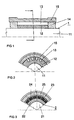
- the rotor 1 of an electrical machine consists of the shaft 11, of the rotor yoke 12 arranged above it on the shaft, which receives conductor rods 13 in longitudinal grooves, which are connected to one another on the two end faces by short-circuit rings 14, and the clamping sleeve 15.
- the rotor yoke 12 is made of a commercially available steel with a strength of 380 N / mm 2
- the adapter sleeve 15 consists of a high-strength steel with a strength of 1,300 N / mm 2 , for example the steel P900N from Krupp.
- the rotor yoke 12 with the inserted conductor bars 13 and the short-circuit rings 14 and the clamping sleeve 15 has first been expanded beyond the yield strength of the rotor yoke material, as a result of which the clamping sleeve 15 the rotor yoke 12 with the inserted conductor bars 13 and the short-circuit rings 14 with high prestress encloses. Subsequently, the active part consisting of the rotor yoke, conductor bars, short-circuit rings and clamping sleeve was applied to the shaft 11 using the technology Two-stage oil press fit "applied.
- FIG. 3 there is the one to be applied to a rotor shaft 21 Active part 2 from a rotor yoke 22, on the outer surface the permanent magnet 23 glued on the rotor yoke, from a protective sleeve 24 in the form of a copper sleeve with a Wall thickness of about 0.8 mm and from the adapter sleeve 25.
- Materials for rotor yoke 22 and adapter sleeve 25 correspond to those of the embodiment according to Figures 1 and 2. Production this active part and applying the active part the rotor shaft 21 take place in the same way as in the exemplary embodiment according to FIG. 1.
Abstract
Description
Die Erfindung liegt auf dem Gebiet der dynamoelektrischen Maschinen und ist bei der konstruktiven Ausgestaltung eines Rotors anzuwenden, dessen äußerer, im Querschnitt kreisringförmiger Bereich zur Erzeugung eines Magnetfeldes dient und hierzu aus einem Läuferjoch, aus in oder auf dem Läuferjoch angeordneten Bauteilen zur Erzeugung des Magnetfeldes und aus einem sich über die ganze Länge des Rotors erstreckenden rohrförmigen Spannhülse besteht.The invention is in the field of dynamoelectric machines and is in the design of a rotor apply, the outer, circular in cross section Area for generating a magnetic field is used and for this purpose from a Läuferjoch, from in or on the Läuferjoch arranged components for generating the magnetic field and from one extending the entire length of the rotor tubular adapter sleeve.
Bei einem bekannten Rotor dieser Art besteht das Läuferjoch aus einem Stapel scheibenförmiger Metall-Lamellen oder aus einem massiven Hohlzylinder aus magnetisierbarem Material; als das Magnetfeld erzeugende Bauteile dienen Permanentmagnet-Segmente, die auf das Läuferjoch aufgeklebt sein können oder mittels einer unter elastischer Vorspannung stehenden dünnen Spannhülse aus einem hochfesten Material wie rostfreiem Stahl auf dem Läuferjoch radial und axial fixiert sind. Die Spannhülse wird dabei durch Aufwärmen aufgeweitet und dann auf die Permanentmagnet-Segmente aufgeschrumpft. Alternativ können die Magnetsegmente zunächst in die Stahlhülse eingesetzt, dann die Magnetsegmente unter Verwendung einer Spreizeinrichtung gespreizt und dadurch die Spannhülse elastisch aufgeweitet und nachfolgend Magnetsegmente und Spannhülse auf das Läuferjoch aufgeschoben werden. Die radialen Abmessungen der verschiedenen Teile sind dabei so dimensioniert, daß nach Abschluß des Zusammenbauens in der Spannhülse eine Restspannung verbleibt, die die Magnetsegmente fest gegen das Läuferjoch preßt und damit bei hohen Drehzahlen den Zentrifugalkräften entgegenwirkt. Dynamoelektrische Maschinen, auf deren Rotor einen solchen Aufbau aufweisen, haben einen Rotordurchmesser von etwa 50 mm, d.h. es handelt sich um dynamoelektrische Maschinen im Leistungsbereich von etwa 1 kW (DE 39 38 007 C2).In a known rotor of this type, there is the rotor yoke from a stack of disc-shaped metal slats or from a massive hollow cylinder made of magnetizable material; permanent magnet segments serve as components generating the magnetic field, that can be glued to the Läuferjoch or by means of an elastic pretension thin adapter sleeve made of a high-strength material such as rustproof Steel fixed radially and axially on the rotor yoke are. The adapter sleeve is expanded by warming up and then shrunk onto the permanent magnet segments. Alternatively the magnetic segments can first be inserted into the steel sleeve inserted, then using a magnetic segments Spreading device spread and thereby the clamping sleeve elastic expanded and subsequently magnetic segments and adapter sleeve be pushed onto the Läuferjoch. The radial Dimensions of the different parts are dimensioned so that after completing assembly in the collet a residual voltage remains that firmly against the magnetic segments the Läuferjoch presses and thus at high speeds Counteracts centrifugal forces. Dynamoelectric machines, have such a structure on the rotor a rotor diameter of about 50 mm, i.e. It is about dynamoelectric machines in the power range of about 1 kW (DE 39 38 007 C2).
Bei anderen bekannten Rotoren für dynamoelektrische Maschinen
wird das Magnetfeld mit Hilfe von in Nuten des Läuferkörpers
eingelegten Wicklungen oder Kurzschlußstäben erzeugt, wobei
die axial aus dem Läuferkörper herausragenden Enden der Kurzschlußstäbe
oder die Wickelköpfe mit Hilfe von Bandagen befestigt
werden. Insbesondere bei Turbogeneratoren dienen als
Bandagen ganzgeschmiedete hohlzylindrische Ringe, die mit dem
einen Rand auf dem Läuferkörper aufsitzen und mit ihrem übrigen,
freitragenden Bereich die Wickelköpfe umfassen. Derartige,
auch als "Kappen" bezeichnete Bandagen werden im warmen
Zustand mit Übermaß aufgesetzt und schrumpfen auf den Läuferkörper
auf. Die Erwärmung der Kappen kann beispielsweise induktiv
erfolgen (DE 25 30 437 A, DE 195 32 848 A1). Es ist
auch bekannt, derartige Kappen vor dem Aufsetzen zu strecken,
d.h. plastisch zu verformen, um ihre Festigkeit zu erhöhen
(DE 21 40 358 A).In other known rotors for dynamo-electric machines, the magnetic field is generated with the aid of windings or short-circuit bars inserted into grooves in the rotor body, the ends of the short-circuit bars or the winding heads projecting axially from the rotor body being fastened with the aid of bandages. In the case of turbogenerators in particular, completely forged hollow cylindrical rings serve as bandages, which rest on the rotor body with one edge and enclose the winding overhangs with their remaining, self-supporting area. Such bandages, also referred to as "caps " , are placed in the warm state with excess and shrink onto the rotor body. The caps can be heated, for example, inductively (
Ausgehend von einem Rotor mit den Merkmalen des Oberbegriffes des Patentanspruches 1 liegt der Erfindung die Aufgabe zugrunde, den äußeren, im Querschnitt kreisringförmigen Bereich des Rotors so auszugestalten, daß auch bei dynamoelektrischen Maschinen, die im Leistungsbereich über 1000 kW arbeiten und mit Drehzahlen über 10.000 U/min betrieben werden, die Fliehkräfte beherrscht werden.Starting from a rotor with the features of the generic term of claim 1, the invention has for its object the outer, circular cross-section of the rotor so that even with dynamoelectric Machines that work in the power range over 1000 kW and operated at speeds above 10,000 rpm, the centrifugal forces be mastered.
Zur Lösung dieser Aufgabe ist gemäß der Erfindung vorgesehen, daß die rohrförmige Spannhülse durch Aufweitung des mit den Bauteilen und der Spannhülse bestückten Läuferjoches über die Streckgrenze des Läuferjochmaterials hinaus radial elastisch vorgespannt ist, wobei der magnetisierbare Stahl des Läuferjoches eine Streckgrenze kleiner/gleich 400 N/mm2 aufweist und die rohrförmige Spannhülse eine Wanddicke von wenigstens 3 mm aufweist und aus einem Stahl der Festigkeit größer 1000 N/mm2 besteht.To achieve this object, it is provided according to the invention that the tubular clamping sleeve is radially elastically prestressed by widening the rotor yoke equipped with the components and the clamping sleeve beyond the yield strength of the rotor yoke material, the magnetizable steel of the rotor yoke having a yield strength less than / equal to 400 N / mm 2 and the tubular clamping sleeve has a wall thickness of at least 3 mm and consists of a steel with a strength greater than 1000 N / mm 2 .
Bei einer derartigen Ausgestaltung des Rotors bilden das Läuferjoch,
die das Magnetfeld erzeugenden Bauteile und die
Spannhülse einen festgefügten Verband, der als komplettes Aktivteil
vorgefertigt und dann auf der Rotorwelle befestigt
wird. Das im Rahmen der Vorfertigung des Aktivteiles erforderliche
plastische Aufweiten des Läuferjoches und die damit
verbundene elastische Aufweitung der Spannhülse kann mittels
einer Vorrichtung erfolgen, die analog zu bekannten Vorrichtungen
ausgestaltet ist, wie sie von der Firma Krupp, DE zur
Aufweitung von Kappenringen für Rotoren von Turbogeneratoren
vertrieben werden (axiale Verschiebung von Doppelkeilen). Das
Aufweiten kann aber auch durch Druckeinwirkung mittels einer
hydraulischen Flüssigkeit erfolgen (ähnlich DE 21 40 358 A).
- Die Befestigung des vorgefertigten kompletten Aktivteiles
auf der Rotorwelle kann mittels des bekannten Ölpreßsitzes
(ähnlich DE 1 200 760 C1) erfolgen. Eine andere Möglichkeit
zur Aufbringung der Vorspannung zwischen Rotorwelle und dem
Aktivteil besteht darin, die bei einer Rotation auftretenden
Fliehkräfte zu nutzen. Hierzu werden die Rotorwelle und das
Läuferjoch gegenläufig leicht kegelig gestaltet und miteinander
in Drehung versetzt. Ein vorgespanntes Federelement
schiebt dann das Aktivteil bei entsprechender Überdrehzahl
axial auf die Rotorwelle auf.With such a configuration of the rotor, the rotor yoke
the components producing the magnetic field and the
Adapter sleeve a firmly attached bandage, which as a complete active part
prefabricated and then attached to the rotor shaft
becomes. The required in the prefabrication of the active part
plastic widening of the runner yoke and with it
connected elastic expansion of the clamping sleeve can by means
a device that is analogous to known devices
is designed as from the company Krupp, DE to
Expansion of cap rings for rotors of turbogenerators
are sold (axial displacement of double wedges). The
But can also expand by the action of pressure by means of a
hydraulic fluid take place (similar to
Zur Herstellung des kompletten Aktivteils aus Läuferjoch, den das Magnetfeld erzeugenden Bauelementen und der Spannhülse wird zweckmäßig eine Spannhülse aus einem Stahl entsprechender Festigkeit verwendet. Geeignet sind aber auch Spannhülsen aus einem durch Keramik- oder Kohlenstoffasern verstärkten Aluminium. For the production of the complete active part from Läuferjoch, the the magnetic field generating components and the adapter sleeve appropriately a clamping sleeve made of steel is appropriate Strength used. But adapter sleeves are also suitable from a reinforced with ceramic or carbon fibers Aluminum.
Beim Aufweiten des Läuferjoches wird dieses elastischplastisch verformt, wozu bei einem Durchmesser des Läuferjoches von etwa 500 mm eine Aufweitung von etwa 3 bis 4 mm erforderlich ist. Der plastische Anteil der Verformung des Läuferjoches, der in der Spannhülse lediglich eine elastische Verformung hervorruft, wirkt sich als innere Vorspannung der Verbindung zwischen Läuferjoch und Spannhülse aus.When the runner yoke expands, it becomes elastic-plastic deformed, for which purpose the diameter of the rotor yoke of about 500 mm, an expansion of about 3 to 4 mm is required is. The plastic part of the deformation of the rotor yoke, the one in the adapter sleeve is only an elastic one Deformation causes, acts as an internal preload of the Connection between the rotor yoke and the adapter sleeve.
Die gemäß der Erfindung vorgesehene Ausgestaltung zur Fixierung der Bauelemente, die der Erzeugung des Magnetfeldes dienen, kann sowohl bei Rotoren zur Anwendung kommen, bei denen das Läuferjoch axiale Nuten zur Aufnahme von Wicklungen oder Leiterstäben aufweist, als auch bei Rotoren, bei denen in das Läuferjoch oder auf das Läuferjoch Permanentmagnete ein- bzw. aufgesetzt werden. Bei Läuferjochen mit aufgeklebten Permanentmagneten wird zweckmäßig zwischen den Permanentmagneten und der Spannhülse eine rohrförmige mechanische Schutzschicht angeordnet, um die Magnete bei der Aufweitung gegen ungleichmäßige Druckbelastung seitens der Spannhülse zu schützen. Als Schutzschicht kommt vorzugsweise eine Kupferschicht in Form einer Hülse in Betracht, gegebenenfalls auch eine Bandage aus harzgetränkter Glasfaserbänderung.The design provided for fixation according to the invention the components used to generate the magnetic field, can be used for rotors where the rotor yoke axial slots for receiving windings or Has conductor bars, as well as in rotors, in which in the Läuferjoch or permanent magnets on the Läuferjoch be put on. For runner yokes with glued permanent magnets is useful between the permanent magnets and the adapter sleeve has a tubular mechanical protective layer arranged to expand the magnets against uneven Protect pressure load on the part of the adapter sleeve. As Protective layer preferably comes in the form of a copper layer a sleeve, possibly also a bandage resin-impregnated fiberglass tape.
Zwei Ausführungsbeispiele des neuen Rotors sind in den Figuren 1 bis 3 dargestellt. Dabei zeigen
- Figur 1 und 2
- einen Läufer mit Kurzschlußwicklung im Längsund Querschnitt und
- Figur 3
- einen Läufer mit Permanentmagneten im Querschnitt.
- Figure 1 and 2
- a rotor with short-circuit winding in the longitudinal and cross-section and
- Figure 3
- a rotor with permanent magnets in cross section.
Gemäß den Figuren 1 und 2 besteht der Rotor 1 einer elektrischen
Maschine aus der Welle 11, aus dem darüber auf der Welle
angeordneten Läuferjoch 12, das in Längsnuten Leiterstäbe
13 aufnimmt, die an den beiden Stirnseiten durch Kurzschlußringe
14 untereinander verbunden sind, und der Spannhülse 15.
Das Läuferjoch 12 ist aus einem handelsüblichen Stahl mit einer
Festigkeit von 380 N/mm2 gefertigt, während die Spannhülse
15 aus einem hochfesten Stahl mit einer Festigkeit von
1 300 N/mm2, beispielsweise dem Stahl P900N der Firma Krupp
besteht. Zur Herstellung dieses Rotors ist zunächst das Läuferjoch
12 mit den eingesetzten Leiterstäben 13 und den Kurzschlußringen
14 sowie der Spannhülse 15 über die Streckgrenze
des Läuferjochmaterials hinaus aufgeweitet worden, wodurch
die Spannhülse 15 das Läuferjoch 12 mit den eingelegten Leiterstäben
13 und den Kurzschlußringen 14 mit hoher Vorspannung
umschließt. Anschließend wurde das aus Läuferjoch, Leiterstäben,
Kurzschlußringen und Spannhülse bestehende Aktivteil
auf die Welle 11 durch Anwendung der Technik
![]()
![]()
Gemäß Figur 3 besteht der auf eine Rotorwelle 21 aufzubringende
Aktivteil 2 aus einem Läuferjoch 22, aus auf die Mantelfläche
des Läuferjoches aufgeklebten Permanentmagneten 23,
aus einer Schutzhülle 24 in Form einer Kupferhülse mit einer
Wandstärke von etwa 0,8 mm und aus der Spannhülse 25. Materialien
für Läuferjoch 22 und Spannhülse 25 entsprechen denen
des Ausführungsbeispieles gemäß den Figuren 1 und 2. Herstellung
dieses Aktivteiles und Aufbringen des Aktivteiles auf
die Rotorwelle 21 erfolgen in gleicher Weise wie bei dem Ausführungsbeispiel
gemäß Figur 1.According to FIG. 3, there is the one to be applied to a
Claims (2)
aus in oder auf dem Läuferjoch angeordneten Bauteilen zur Erzeugung des Magnetfeldes
und aus einer sich über die ganze Länge des Rotors erstrekkenden, im Preßsitz aufsitzenden rohrförmigen Spannhülse aus einem hochfesten Metall besteht,
dadurch gekennzeichnet,
daß die rohrförmige Spannhülse (15) durch Aufweitung des mit den Bauteilen (13) und der Spannhülse bestückten Läuferjoches (12) über die Streckgrenze des Läuferjochmaterials hinaus radial elastisch vorgespannt ist,
wobei der magnetisierbare Stahl des Läuferjochs (12) eine Streckgrenze kleiner/gleich 400 N/mm2 aufweist und die rohrförmige Spannhülse (15) eine Wanddicke von wenigstens 3 mm aufweist und aus einem Stahl der Festigkeit größer 1000 N/mm2 besteht.Rotor for a dynamoelectric machine, the outer area of which is circular in cross-section and consists of a rotor yoke made of a magnetizable steel,
from components arranged in or on the rotor yoke for generating the magnetic field
and consists of a tubular clamping sleeve which extends over the entire length of the rotor and is seated in the press fit and is made of a high-strength metal,
characterized,
that the tubular clamping sleeve (15) is radially elastically biased beyond the yield point of the rotor yoke material by widening the rotor yoke (12) equipped with the components (13) and the clamping sleeve,
wherein the magnetizable steel of the rotor yoke (12) has a yield strength of less than or equal to 400 N / mm 2 and the tubular clamping sleeve (15) has a wall thickness of at least 3 mm and consists of a steel with a strength greater than 1000 N / mm 2 .
dadurch gekennzeichnet,
daß die zur Erzeugung des Magnetfeldes dienenden Bauteile aus auf das Läuferjoch (22) aufgeklebten Permanentmagneten(23) bestehen und daß zwischen diesen Permanentmagneten (23) und der Spannhülse (25) eine rohrförmige mechanische Schutzschicht (24) angeordnet ist.Rotor according to claim 1,
characterized,
that the components used to generate the magnetic field consist of permanent magnets (23) glued onto the rotor yoke (22) and that a tubular mechanical protective layer (24) is arranged between these permanent magnets (23) and the clamping sleeve (25).
Applications Claiming Priority (2)
| Application Number | Priority Date | Filing Date | Title |
|---|---|---|---|
| DE19736710 | 1997-08-18 | ||
| DE19736710A DE19736710B4 (en) | 1997-08-18 | 1997-08-18 | Rotor for a dynamoelectric machine |
Publications (3)
| Publication Number | Publication Date |
|---|---|
| EP0977340A2 true EP0977340A2 (en) | 2000-02-02 |
| EP0977340A3 EP0977340A3 (en) | 2001-04-18 |
| EP0977340B1 EP0977340B1 (en) | 2002-10-30 |
Family
ID=7839936
Family Applications (1)
| Application Number | Title | Priority Date | Filing Date |
|---|---|---|---|
| EP98250294A Expired - Lifetime EP0977340B1 (en) | 1997-08-18 | 1998-08-18 | Rotor for a dynamoelectric machine |
Country Status (3)
| Country | Link |
|---|---|
| EP (1) | EP0977340B1 (en) |
| JP (1) | JP4057710B2 (en) |
| DE (1) | DE19736710B4 (en) |
Cited By (1)
| Publication number | Priority date | Publication date | Assignee | Title |
|---|---|---|---|---|
| US10951101B2 (en) | 2015-12-08 | 2021-03-16 | Rolls-Royce Plc | Induction motor rotor and a method of manufacturing the same |
Families Citing this family (4)
| Publication number | Priority date | Publication date | Assignee | Title |
|---|---|---|---|---|
| DE10224776A1 (en) | 2002-06-04 | 2004-03-11 | Magnet-Motor Gesellschaft Für Magnetmotorische Technik Mbh | Electrical machine |
| CN102582118B (en) * | 2012-03-05 | 2013-05-22 | 浙江超伟机械有限公司 | Bag maker |
| EP2887502B1 (en) | 2013-12-18 | 2016-10-05 | Skf Magnetic Mechatronics | Rotor assembly with permanent magnets and method of manufacture |
| CN111682663A (en) * | 2020-06-11 | 2020-09-18 | 哈尔滨电气动力装备有限公司 | Solid rotor structure of asynchronous motor |
Citations (4)
| Publication number | Priority date | Publication date | Assignee | Title |
|---|---|---|---|---|
| DE2140358A1 (en) * | 1971-08-11 | 1973-06-20 | Mo Wysschee Tekhn Utschilischt | STRETCHING PROCEDURE FOR BANDAGE RINGS AND PRESSING EQUIPMENT TO PERFORM THIS PROCESS |
| DE3938007A1 (en) * | 1989-02-06 | 1990-08-23 | Franklin Electric Co Inc | METHOD AND DEVICE FOR PRODUCING A PERMANENT MAGNETIC RUNNER FOR AN ELECTRIC MOTOR |
| US5486730A (en) * | 1993-03-18 | 1996-01-23 | Solar Turbines Incorporated | Rotor assembly |
| US5563463A (en) * | 1988-06-08 | 1996-10-08 | General Electric Company | Permanent magnet rotor |
Family Cites Families (2)
| Publication number | Priority date | Publication date | Assignee | Title |
|---|---|---|---|---|
| DE2530437B2 (en) * | 1975-07-08 | 1979-04-19 | Galina Alexandrovna Zagorodnaya Geb. Poluektova | Cylinder jacket-shaped bandage (rotor cap) for fastening the end winding of the rotor winding of an electrical machine |
| DE19532848A1 (en) * | 1995-09-06 | 1997-03-13 | Abb Patent Gmbh | Generator rotor cap fitting and removal method |
-
1997
- 1997-08-18 DE DE19736710A patent/DE19736710B4/en not_active Expired - Lifetime
-
1998
- 1998-08-17 JP JP23095898A patent/JP4057710B2/en not_active Expired - Fee Related
- 1998-08-18 EP EP98250294A patent/EP0977340B1/en not_active Expired - Lifetime
Patent Citations (4)
| Publication number | Priority date | Publication date | Assignee | Title |
|---|---|---|---|---|
| DE2140358A1 (en) * | 1971-08-11 | 1973-06-20 | Mo Wysschee Tekhn Utschilischt | STRETCHING PROCEDURE FOR BANDAGE RINGS AND PRESSING EQUIPMENT TO PERFORM THIS PROCESS |
| US5563463A (en) * | 1988-06-08 | 1996-10-08 | General Electric Company | Permanent magnet rotor |
| DE3938007A1 (en) * | 1989-02-06 | 1990-08-23 | Franklin Electric Co Inc | METHOD AND DEVICE FOR PRODUCING A PERMANENT MAGNETIC RUNNER FOR AN ELECTRIC MOTOR |
| US5486730A (en) * | 1993-03-18 | 1996-01-23 | Solar Turbines Incorporated | Rotor assembly |
Cited By (1)
| Publication number | Priority date | Publication date | Assignee | Title |
|---|---|---|---|---|
| US10951101B2 (en) | 2015-12-08 | 2021-03-16 | Rolls-Royce Plc | Induction motor rotor and a method of manufacturing the same |
Also Published As
| Publication number | Publication date |
|---|---|
| EP0977340B1 (en) | 2002-10-30 |
| DE19736710B4 (en) | 2005-05-25 |
| EP0977340A3 (en) | 2001-04-18 |
| JP4057710B2 (en) | 2008-03-05 |
| DE19736710A1 (en) | 1999-02-25 |
| JPH11136887A (en) | 1999-05-21 |
Similar Documents
| Publication | Publication Date | Title |
|---|---|---|
| EP2389511B1 (en) | Magnet wheel | |
| EP2569848B1 (en) | Method for producing an electric motor | |
| DE1942855A1 (en) | Runner of an electrical machine | |
| DE4320894C2 (en) | Rotor for electrical machines and methods of manufacturing the same | |
| DE102014104677A1 (en) | Rotor part for attachment to the shaft of a rotating electric motor, rotor with rotor part, and method for producing a rotating electric motor and a rotor | |
| DE2737959B2 (en) | Arrangement for tensioning an air gap winding in the stator of an electrical machine | |
| DE2924863C2 (en) | Arrangement for fastening an air gap winding | |
| DE2953033A1 (en) | RUNNERS WITH PROPELLED POLES FOR ELECTRICAL MACHINES | |
| DE3245699A1 (en) | COMMUTATOR AND METHOD FOR THE PRODUCTION THEREOF | |
| DE102009005956A1 (en) | magnetic ring | |
| EP0977340B1 (en) | Rotor for a dynamoelectric machine | |
| EP2896837B1 (en) | Method for producing a rotor assembly for a vacuum pump and rotor assembly for a vacuum pump | |
| WO1999012246A1 (en) | Electric motor | |
| EP1678806A1 (en) | Permanent magnet rotor of an electric machine, providing great thermal resistance | |
| DE2333621A1 (en) | ROTOR WINDING HEAD SUPPORT FOR FAST RUNNING ELECTRICAL MACHINERY, IN PARTICULAR TURBOGEN GENERATOR | |
| DE4239754C2 (en) | Runner for an electrical machine | |
| DE102018206138A1 (en) | Housing of an electric motor | |
| EP2006979B1 (en) | Method for manufacturing an electric generator rotor shaft for generating electricity in power plants | |
| AT202638B (en) | Process for the production of stator sets from two cylindrical, telescoping parts made of ferromagnetic material | |
| DE102018204437A1 (en) | Method for mounting a component on a hollow shaft and a rotor produced in this way for an electrical machine | |
| EP3261222A2 (en) | Rotor system for an electric machine, electrical machine comprising the rotor system, and a method of producing the rotor system | |
| DE2724009A1 (en) | METHOD AND DEVICE FOR MANUFACTURING A STAND FOR A DYNAMOELECTRIC MACHINE | |
| EP3261217B1 (en) | Rotor system for an electric machine, electrical machine comprising the rotor system, and a method of producing the rotor system | |
| DE102022103645A1 (en) | Method of manufacturing an electric machine component, electric machine component and electric machine | |
| DE1072307B (en) |
Legal Events
| Date | Code | Title | Description |
|---|---|---|---|
| PUAI | Public reference made under article 153(3) epc to a published international application that has entered the european phase |
Free format text: ORIGINAL CODE: 0009012 |
|
| AK | Designated contracting states |
Kind code of ref document: A2 Designated state(s): CH FI FR IT LI |
|
| AX | Request for extension of the european patent |
Free format text: AL;LT;LV;MK;RO;SI |
|
| PUAL | Search report despatched |
Free format text: ORIGINAL CODE: 0009013 |
|
| AK | Designated contracting states |
Kind code of ref document: A3 Designated state(s): AT BE CH CY DE DK ES FI FR GB GR IE IT LI LU MC NL PT SE |
|
| AX | Request for extension of the european patent |
Free format text: AL;LT;LV;MK;RO;SI |
|
| 17P | Request for examination filed |
Effective date: 20010806 |
|
| AKX | Designation fees paid |
Free format text: CH FI FR IT LI |
|
| REG | Reference to a national code |
Ref country code: DE Ref legal event code: 8566 |
|
| GRAG | Despatch of communication of intention to grant |
Free format text: ORIGINAL CODE: EPIDOS AGRA |
|
| GRAG | Despatch of communication of intention to grant |
Free format text: ORIGINAL CODE: EPIDOS AGRA |
|
| GRAH | Despatch of communication of intention to grant a patent |
Free format text: ORIGINAL CODE: EPIDOS IGRA |
|
| 17Q | First examination report despatched |
Effective date: 20020314 |
|
| GRAH | Despatch of communication of intention to grant a patent |
Free format text: ORIGINAL CODE: EPIDOS IGRA |
|
| GRAA | (expected) grant |
Free format text: ORIGINAL CODE: 0009210 |
|
| AK | Designated contracting states |
Kind code of ref document: B1 Designated state(s): CH FI FR IT LI |
|
| REG | Reference to a national code |
Ref country code: CH Ref legal event code: NV Representative=s name: SIEMENS SCHWEIZ AG Ref country code: CH Ref legal event code: EP |
|
| ET | Fr: translation filed | ||
| PLBE | No opposition filed within time limit |
Free format text: ORIGINAL CODE: 0009261 |
|
| STAA | Information on the status of an ep patent application or granted ep patent |
Free format text: STATUS: NO OPPOSITION FILED WITHIN TIME LIMIT |
|
| 26N | No opposition filed |
Effective date: 20030731 |
|
| PG25 | Lapsed in a contracting state [announced via postgrant information from national office to epo] |
Ref country code: IT Free format text: LAPSE BECAUSE OF NON-PAYMENT OF DUE FEES Effective date: 20050818 |
|
| REG | Reference to a national code |
Ref country code: CH Ref legal event code: PCAR Free format text: SIEMENS SCHWEIZ AG;INTELLECTUAL PROPERTY FREILAGERSTRASSE 40;8047 ZUERICH (CH) |
|
| PGFP | Annual fee paid to national office [announced via postgrant information from national office to epo] |
Ref country code: CH Payment date: 20121113 Year of fee payment: 15 |
|
| PGFP | Annual fee paid to national office [announced via postgrant information from national office to epo] |
Ref country code: FI Payment date: 20130813 Year of fee payment: 16 |
|
| PGFP | Annual fee paid to national office [announced via postgrant information from national office to epo] |
Ref country code: FR Payment date: 20130814 Year of fee payment: 16 |
|
| REG | Reference to a national code |
Ref country code: CH Ref legal event code: PL |
|
| PG25 | Lapsed in a contracting state [announced via postgrant information from national office to epo] |
Ref country code: LI Free format text: LAPSE BECAUSE OF NON-PAYMENT OF DUE FEES Effective date: 20130831 Ref country code: CH Free format text: LAPSE BECAUSE OF NON-PAYMENT OF DUE FEES Effective date: 20130831 |
|
| PG25 | Lapsed in a contracting state [announced via postgrant information from national office to epo] |
Ref country code: FI Free format text: LAPSE BECAUSE OF NON-PAYMENT OF DUE FEES Effective date: 20140818 |
|
| REG | Reference to a national code |
Ref country code: FR Ref legal event code: ST Effective date: 20150430 |
|
| PG25 | Lapsed in a contracting state [announced via postgrant information from national office to epo] |
Ref country code: FR Free format text: LAPSE BECAUSE OF NON-PAYMENT OF DUE FEES Effective date: 20140901 |