EP0975432B1 - An improved spraying device - Google Patents
An improved spraying device Download PDFInfo
- Publication number
- EP0975432B1 EP0975432B1 EP98905076A EP98905076A EP0975432B1 EP 0975432 B1 EP0975432 B1 EP 0975432B1 EP 98905076 A EP98905076 A EP 98905076A EP 98905076 A EP98905076 A EP 98905076A EP 0975432 B1 EP0975432 B1 EP 0975432B1
- Authority
- EP
- European Patent Office
- Prior art keywords
- fluid
- cartridge
- gear
- trigger
- spraying apparatus
- Prior art date
- Legal status (The legal status is an assumption and is not a legal conclusion. Google has not performed a legal analysis and makes no representation as to the accuracy of the status listed.)
- Expired - Lifetime
Links
Images

Classifications
-
- B—PERFORMING OPERATIONS; TRANSPORTING
- B05—SPRAYING OR ATOMISING IN GENERAL; APPLYING FLUENT MATERIALS TO SURFACES, IN GENERAL
- B05B—SPRAYING APPARATUS; ATOMISING APPARATUS; NOZZLES
- B05B7/00—Spraying apparatus for discharge of liquids or other fluent materials from two or more sources, e.g. of liquid and air, of powder and gas
- B05B7/24—Spraying apparatus for discharge of liquids or other fluent materials from two or more sources, e.g. of liquid and air, of powder and gas with means, e.g. a container, for supplying liquid or other fluent material to a discharge device
- B05B7/2402—Apparatus to be carried on or by a person, e.g. by hand; Apparatus comprising containers fixed to the discharge device
- B05B7/244—Apparatus to be carried on or by a person, e.g. by hand; Apparatus comprising containers fixed to the discharge device using carrying liquid for feeding, e.g. by suction, pressure or dissolution, a carried liquid from the container to the nozzle
- B05B7/2443—Apparatus to be carried on or by a person, e.g. by hand; Apparatus comprising containers fixed to the discharge device using carrying liquid for feeding, e.g. by suction, pressure or dissolution, a carried liquid from the container to the nozzle the carried liquid and the main stream of carrying liquid being brought together downstream of the container before discharge
-
- B—PERFORMING OPERATIONS; TRANSPORTING
- B05—SPRAYING OR ATOMISING IN GENERAL; APPLYING FLUENT MATERIALS TO SURFACES, IN GENERAL
- B05B—SPRAYING APPARATUS; ATOMISING APPARATUS; NOZZLES
- B05B12/00—Arrangements for controlling delivery; Arrangements for controlling the spray area
- B05B12/002—Manually-actuated controlling means, e.g. push buttons, levers or triggers
-
- B—PERFORMING OPERATIONS; TRANSPORTING
- B05—SPRAYING OR ATOMISING IN GENERAL; APPLYING FLUENT MATERIALS TO SURFACES, IN GENERAL
- B05B—SPRAYING APPARATUS; ATOMISING APPARATUS; NOZZLES
- B05B7/00—Spraying apparatus for discharge of liquids or other fluent materials from two or more sources, e.g. of liquid and air, of powder and gas
- B05B7/02—Spray pistols; Apparatus for discharge
- B05B7/12—Spray pistols; Apparatus for discharge designed to control volume of flow, e.g. with adjustable passages
- B05B7/1209—Spray pistols; Apparatus for discharge designed to control volume of flow, e.g. with adjustable passages the controlling means for each liquid or other fluent material being manual and interdependent
Definitions
- This invention relates to the field of chemical application. More specifically, the invention is an apparatus which dilutes and dispenses a chemical which is stored in an interchangeable cartridge, typically for lawn and garden application.
- Typical hose end lawn or garden sprayers are aspirator units which apply fertilizers, pesticides or other chemicals at a fixed, low dilution ratio.
- the user normally predilutes the concentrate with water. This is accomplished by volume measurement of the concentrate with a spoon, cap or other measuring device into a sprayer mix jar. Water is then added to obtain the proper premix concentration. The prediluted concentrate is then further diluted to the final dilution ratio as the sprayer is operated.
- U.S. Pat. No. 3,165,114 issued to Garrett discloses a dispensing package of fluid soluble material capable of use with a standard feed mixer device. Some of the flowing water is diverted down through a nipple and inlet tube into the bottom of the package. Suction draws the dissolved material through an outlet tube. The device requires water to constantly flow through it, and does not provide a barrel valve which could shut off or control the flow.
- U.S. Pat. No. 3,198,438 issued to Hultgren, et al. requires a trigger action to push a tapered plug out of an aperture, allowing water to flow into a mixing chamber to create a venturi suction to draw fluid out of a collapsible container.
- U.S. Pat. No. 3,255,972 also issued to Hultgren, et al. discloses a disposable container for use with sprayers of the type disclosed in the '438 patent.
- U.S. Pat. No. 3,554,450, issued to D'Muhala teaches a spray gun which accommodates removable cartridges containing various solids or liquids. An end cap is unscrewed to control water through a mixing chamber and out a nozzle.
- U.S. Pat. No. 3,915,191 discloses a water mixing device for a shower which may be fitted to the taps of a bath.
- a selector valve selectively permits water from an inlet chamber to flow through various enclosures of a second chamber.
- At least one (1) enclosure has a container to receive a soluble substance such as soap. No initial dissolution of the soap is provided for, and the soap is transported by direct flow of the water, and not drawn by aspiration.
- U.S. Pat. No. 4,491,254 issued to Viets, et al. teaches an applicator for dispensing a chemical in dilute aqueous form.
- the applicator has two (2) containers.
- the second container receives a chemical which has been diluted with water from the first container.
- a two-position, rotatable valve directs the flow of water into either the first container to predilute a chemical, or to flow across an aspirator to mix with the prediluted chemical and discharge it through the exit end of a passageway.
- Viet's device requires removing caps from the containers to add chemicals, and to thread the containers together to attach them, a cumbersome and potentially unsafe procedure.
- the valve taught by Viets, et al. only has two (2) positions. Water is constantly flowing either into the second container to dilute a chemical or through the passageway. An operator must use a conventional nozzle, which must be specially adapted to attach to the applicator to turn the water on or off to control
- U.S. patent No. 5,213,264 to Styne teaches a spraying apparatus having a sprayer head and a cartridge.
- a barrel valve controls whether an entering fluid flows directly into a mixing chamber, or flows through a tube into the cartridge, or does not flow at all.
- a membrane is required at the top of the cartridge, and is punctured by sprayer head tubes during attachment.
- U.S. patent No. 5,332.158 to Styne teaches a spraying device with an interchangeable cartridge. More specifically, U.S. patent No. 5.332.158 teaches a sprayer having a fluid inlet port which directs fluid into a mixing conduit. An aspirator port connects the mixing conduit with a second fluid in the cartridge. A vent port in the sprayer head connects with a vent in the cartridge to reduce the pressure differential in order to allow proper aspiration and reduce leaks.
- a nozzle means permits a controlled jet spray.
- Document GB-A-j28537 describes a spraying apparatus having a needle valve controlled by a rotating core, journaled in a body and means for actuating said valve.
- the prior work is limited in the attempts to easily, economically, safely, and environmentally provide a device to dilute and dispense various insecticides, herbicides, cleaners, and fertilizers.
- a spraying device that keeps the chemical in a closed system until the operator engages the trigger.
- a sprayer in which the metering orifice is preset so that the end user does not have to worry about adjusting the water to chemical ratio.
- the sprayer of the present invention has an unique trigger arrangement.
- a gear engages and rotates a ball valve gear, which in turn, rotates a ball valve thereby opening a water fluid path.
- the ball gear engages and rotates a fork gear which depresses a slider cam which, in turn, depresses a metering valve in the chemical fluid cartridge that opens a chemical fluid path.
- the trigger has an extension that engages one end of a cantilever. As the trigger engages one end of the cantilever, the other end of the cantilever engages a cam. The cam, in turn, engages and depresses a metering valve.
- the depressed movement of the metering cam opens the fluid path to the chemical cartridge.
- This structural arrangement provides a closed chemical system and maintains the closed system even after cartridge is assembled onto the sprayer, thus, creating a sprayer that is safer than prior art sprayers where the chemical path remains constantly open once the chemical cartridge is installed onto the sprayer.
- the unique gear arrangement also provides for a more positive operation than prior art sprayers.
- the sprayer of the present invention also includes a premolded metering adapter wherein the orifice diameter is preset during manufacturing based on physical testing.
- a premolded metering adapter wherein the orifice diameter is preset during manufacturing based on physical testing.
- the sprayer of the present invention also includes an improved means of securing the cartridge shroud to the sprayer.
- the cartridge shroud is secured to the sprayer head by means of a bayonet fitting which is rotated onto the sprayer using a protruding slider cam as a means of orienting the cartridge to the sprayer.
- the cartridge bottle is then secured to the cartridge shroud by means of locking latches in the shroud which are secured under a valve closure threaded onto the bottle neck finish.
- the spraying device of the present invention generally consists of three primary parts: (1) a spraying head, (2) a cartridge shroud, and (3) a cartridge bottle.
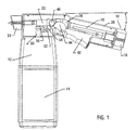
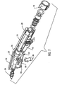
- Figures 1-4 and 7 illustrate one embodiment of the spraying device of the present invention.
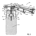
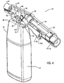
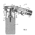
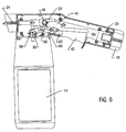
- Figures 5 and 6 illustrate the preferred embodiment of the present invention.
- sprayer head 10 is operatively secured to cartridge shroud 12, which in turn, is secured to cartridge bottle 14.
- a first fluid typically water
- Hose nut fitting 16 reduces leakage from the source of the first fluid, such as a garden hose, that enters the fluid inlet conduit 18.
- the hose nut fitting 16 may include an anti-siphon unit, which are well known in the art, for preventing back flow and leaking from fluid inlet conduit 18.
- Fluid inlet conduit 18 is disposed in a housing 20. which provides support to sprayer head 10 to enhance fluid flow through the referenced conduits, ports and other passages. Any suitable material, such as plastic, may comprise the housing.
- the first end of fluid inlet conduit 18 is connected to hose nut fitting 16.
- the second end of fluid inlet conduit 18 is operatively connected to the first end of an outlet fluid conduit 22.
- the second end of the outlet fluid conduit is operatively connected to nozzle means 24 which provides a jet spray. It is desirable that nozzle means 24 be adjustable to spray up or down or to selectively provide a jet spray. Nozzle means are well known in the art.
- Outlet fluid conduit 22 is, like inlet fluid conduit 18, disposed in housing 20.
- Inlet fluid conduit 18 is operatively connected at its second end to the first end of outlet fluid conduit 22, either directly as shown in Figures 5 and 6 or as shown in Figures 1-4 and 7 by means of a flex tube 26, which can be made of any suitable material.
- Flex tube 26 simply provides a means of providing fluid communication between inlet fluid conduit 18 and outlet fluid conduit 22 while also providing an angled connection of the conduits in order for the conduits to be in an angled offset relationship, as shown by the letter "a" in Figure 1.
- inlet fluid conduit 18 may have a built-in angled offset in order to provide the offset denoted by the letter "a.”
- the passage created by hose nut 16, inlet fluid conduit 18, (with or without flex tube 26), outlet fluid conduit 22 and nozzle means 24 provides for fluid communication of the first fluid throughout sprayer head 10.
- a cartridge shroud 12 is secured to sprayer head 10 by means of a bayonet fitting which is rotated onto sprayer head 10 using a protruding slider cam 30 as a means of orienting it to sprayer head 10.
- the bayonet fitting is primarily accomplished by a locking tab arrangement as best shown in Figure 4.
- Locking tabs 32 slidably engage and lock into the slots created by U-shaped legs 34 of housing 20.
- the user may use slider cam 30 to orient cartridge shroud 12 to sprayer head 10. Once oriented, the operator may rotate cartridge shroud 12 and align locking tabs 32 into the slots formed by legs 34 until locking tabs 32 are secured in place.
- Cartridge shroud 12 safely covers the sprayer head 10 to cartridge bottle 14 connection.
- Cartridge bottle 14 is an especially useful device for containing a second fluid therein.
- the second fluid can be any fluid that, when diluted with the first fluid, becomes suitable for discharge into the environment for any of several uses, such as a pesticide, herbicide, insecticide, waxing, or washing product, engine cleaner, road surface cleaner, or fertilizer.
- cartridge bottle 14 is secured to cartridge shroud 12 by means of locking latches 36 which are secured under valve closure 38 which is threaded on the bottle neck finish.
- the outer surface of cartridge shroud 12 extends over the outer surface of cartridge bottle 14, and is further secured to cartridge bottle 14 by tabs 40.
- the primary purpose of the spraying apparatus of the present invention is to mix the first fluid, such as water, with a predetermined amount of the second fluid, such as a chemical, and dispense the mixture into the environment.
- a novel feature of the spraying apparatus of the present invention is the way in which the first and second fluids are mixed and dispensed.
- the second fluid typically a chemical
- the second fluid is stored in a closed system in cartridge bottle 14.
- the second fluid can only be dispensed by the engagement of a trigger 42 when the cartridge bottle 14 is assembled to the mating sprayer head 10. That is, the second fluid remains in a closed system in cartridge bottle 14 even after cartridge bottle 14 is operatively attached to sprayer head 10. Moreover, once cartridge bottle 14 is removed from sprayer head 10, the flow path out of cartridge bottle 14 automatically closes and keeps the second fluid supply within a closed system.
- Trigger 42 is operatively attached to housing 20.
- trigger 42 is generally located under fluid inlet conduit 18.
- a spring 44a biases trigger 42 in a neutral position (pathways for both first and second fluids are closed) until engaged and activated by the operator.
- Trigger 42 further includes as one piece, or is operatively connected to as a separate piece, trigger gear 44. In either embodiment, movement of trigger 42 causes trigger gear 44 to rotate as trigger 42 is activated by the operator.
- trigger gear 44 is operatively engaged with valve gear 46 such that, as trigger gear 44 rotates, it causes ball valve gear 46 to likewise rotate.
- Ball valve gear 46 is operatively connected to valve 48.
- valve 48 is preferably a ball valve disposed in outlet fluid conduit 22. In a closed position, valve 48 prevents the passage of the first fluid through outlet fluid conduit 22. In a fully rotated, or open position, valve 48 allows the first fluid to flow from inlet fluid conduit 18 into, and through, outlet fluid conduit 22.
- outlet fluid conduit 22 comprises at least three ends or openings.
- the first opening is in a fluid communication relationship with inlet fluid conduit 18 by means of flex tube 26.
- the second opening, or end is in a fluid communication relationship with nozzle 24.
- the third end, or opening, of outlet fluid conduit 22 is in fluid communication with the second fluid in cartridge bottle 14 by means of a fluid path 50.
- valve gear 46 As discussed above, activation of trigger 42 rotates trigger gear 44, which in turn, engages and rotates valve gear 46, which in turn, engages and rotates valve 48 to an open position. Further movement of trigger 42 causes valve gear 46 to further rotate and engage fork gear assembly 52, which primarily comprises a gear 54 and a fork 56. As gear 54 is rotated by valve gear 46, fork 56 is moved, preferably, in a downward or depressed position. As fork 56 moves downwardly, it engages and depresses slider cam 30 in a downward position. As slider cam 30 is depressed by fork gear assembly 52, it depresses, and opens, a metering valve 58 disposed in fluid path 50; thereby opening fluid path 50 and allowing the second fluid to flow into outlet fluid conduit 22. The second fluid is drawn up fluid path 50 by means of a vacuum created in fluid path 50 by the flow of the first fluid in outlet fluid conduit 22. The first and second fluids mix in the outlet fluid conduit 22 prior to dispensing into the environment through nozzle means 24.
- trigger gear 44 is operatively engaged with valve gear 46 such that, as trigger gear 44 rotates, it causes ball valve gear 46 to likewise rotate.
- Ball valve gear 46 is operatively connected to valve 48.
- valve 48 is preferably a ball valve disposed in outlet fluid conduit 22. In a closed position, valve 48 prevents the passage of the first fluid through outlet fluid conduit 22. In a fully rotated, or open position, valve 48 allows the first fluid to flow from inlet fluid conduit 18 into, and through, outlet fluid conduit 22.
- outlet fluid conduit 22 comprises at least three ends or openings.
- the first opening is in a fluid communication relationship with inlet fluid conduit 18 by means of flex tube 26.
- the second opening, or end is in a fluid communication relationship with nozzle 24.
- the third end, or opening, of outlet fluid conduit 22 is in fluid communication with the second fluid in cartridge bottle 14 by means of a fluid path 50.
- trigger 42 engages cantilever 64. More particularly, trigger 42 has an extension portion 62 that engages one end of cantilever 64. As one end of cantilever 64 is engaged and moved in one direction, the opposite end of cantilever 64 moves in the opposite direction. The opposite end of cantilever 64, in turn, engages and moves cam and fork assembly 66 which also operates in a cantilever fashion. More particularly, as cantilever 64 engages and moves an extension portion of cam and fork assembly 66, fork portion 68 (as shown in Figure 6) engages and depresses slider cam 30 in a downward position.
- slider cam 30 As slider cam 30 is depressed by fork portion 68 of cam and fork assembly 66, it opens metering valve 58 disposed in fluid path 50; thereby opening fluid path 50 and allowing the second fluid to flow into outlet fluid conduit 22.
- the second fluid is drawn up fluid path 50 by means of a vacuum created in fluid path 50 by the flow of the first fluid in outlet fluid conduit 22.
- the first and second fluids mix in the outlet fluid conduit 22 prior to dispensing into the environment through nozzle means 24.
- the mix ratio of the first and second fluids is determined by orifice valve 60 (as shown in Figure 3) preferably affixed to the upper end of metering valve 58.
- the mix ratio of first fluid to second fluid is predetermined and set by the manufacturer by varying the diameter of orifice valve 60.
- the orifice valve 60 is premolded and the orifice dimension is established through physical testing by the manufacturer with the particular chemical fluid or product. The end user does not, and in fact, cannot, tamper with, or adjust, the mix ratio. Rather, different cartridge bottles 14 are purchased for different applications. Thus, the concentrations of different chemicals are adjusted to provide the proper mix ratio through the standard orifice diameter of orifice valve 60.
Abstract
Description
Claims (14)
- A spraying apparatus comprising:characterized in thata spraying head (10) operatively connected to a cartridge bottle (14), said cartridge bottle containing a second fluid;said spraying head comprising:an inlet conduit (18) for receiving a first fluid, said inlet conduit having a first end and a second end;a trigger (42);an outlet conduit (22) having a first end in fluid communication with said second end of said inlet conduit, said outlet conduit having a second end in fluid communication with the environment, and a third end in fluid communication with said second fluid in said cartridge;means for opening a fluid path (50) to said second fluid in said cartridge thereby causing said second fluid to mix with said first fluid prior to dispensing of mixture into the environment;a valve (48) disposed in said outlet conduit,
said valve (48) is a ball valve rotating in response to movement of said trigger allowing the passage of said first fluid from said inlet conduit to the environment, and said means for opening a fluid path includes a gear assembly, said gear assembly having a first gear (44) engaged and rotated in response to movement of said trigger, said gear assembly having a second gear (46) operatively connected to said ball valve, and a third gear (54) operatively connected to a fork (56) for opening said fluid path (50) for said second fluid. - The spraying apparatus of claim 1 further comprising a cartridge shroud (12) secured to said spraying head at one end, and secured to said cartridge bottle at its other end.
- The spraying apparatus of claim 1 wherein movement of said trigger causes said first gear to engage and rotate said second gear, which in turn, engages and rotates said ball valve, further movement of said trigger causes second gear to engage and rotate said third gear, which in turn, opens said path to said second fluid and allows said second fluid to mix with said first fluid prior to dispensing into the environment.
- The spraying apparatus of claim 3 wherein a metering adapter (60) is disposed in said fluid path to said cartridge bottle, said metering adapter controls the amount of said second fluid to be mixed with said first fluid.
- The spraying apparatus of claim 2 wherein said cartridge shroud further comprises at least one locking tab (32) to secure said cartridge shroud to said spraying head.
- The spraying apparatus of claim 1 further comprising a nozzle means (24) which provides a jet spray.
- The spraying apparatus of claim 1 wherein said cartridge bottle maintains said second fluid as a closed system until said trigger is engaged by the operator.
- The spraying apparatus of claim 1 further comprising a hose-nut fitting means disposed near said first end of said inlet conduit to reduce any leakage from a source of said first fluid entering said inlet conduit.
- A spraying apparatus according to claim 4 further comprising a means for engaging said metering adapter to cause said second fluid to mix with said first fluid.
- The spraying apparatus of claim 9 wherein said metering adapter is affixed to an end of an upper valve stem (58) in said cartridge, said metering adapter having a predetermined orifice diameter.
- The spraying apparatus of any of the preceding claims further comprising a cartridge shroud (12)having a first end and a second end, said first end of said shroud secured to said sprayer head, said second end of said shroud secured to said cartridge.
- The spraying apparatus of claim 11 wherein said first end of said shroud is secured to said sprayer head by locking tabs (32) and said second end of said shroud secured to said cartridge by locking latches (36).
- The spraying apparatus of claim 9 further comprising a slider cam (30) operatively connected to said fork at one end and said metering adapter at its other end.
- A spraying apparatus according to claim 1
characterized in that
the ball valve (48) is disposed in said outlet conduit, and has a ball valve gear (46);
the trigger has a gear (44) operatively engageable with said ball valve gear such that, movement of said trigger opens said ball valve, said trigger further engageable with a cantilever (64), said cantilever has a first end and a second end such that, in response to movement of said trigger, said trigger engages and moves of said first end of said cantilever in a first direction, thereby moving said second end of said cantilever in a second direction; it further comprises a cam and fork assembly (66) having a fork portion (68), said cam and fork assembly engageable with said cantilever such that said second end of said cantilever engages and moves said cam and fork assembly, said cam and fork assembly is operatively engageable with a metering adapter (60) such that, upon movement, said fork portion engages and depresses said metering adapter thereby dispensing said second fluid from said cartridge bottle into said outlet conduit for mixing with said first fluid and dispensing into the environment.
Applications Claiming Priority (3)
| Application Number | Priority Date | Filing Date | Title |
|---|---|---|---|
| US837352 | 1986-03-07 | ||
| US08/837,352 US5881955A (en) | 1997-04-17 | 1997-04-17 | Spraying device |
| PCT/US1998/002825 WO1998046366A1 (en) | 1997-04-17 | 1998-02-16 | An improved spraying device |
Publications (2)
| Publication Number | Publication Date |
|---|---|
| EP0975432A1 EP0975432A1 (en) | 2000-02-02 |
| EP0975432B1 true EP0975432B1 (en) | 2005-11-30 |
Family
ID=25274214
Family Applications (1)
| Application Number | Title | Priority Date | Filing Date |
|---|---|---|---|
| EP98905076A Expired - Lifetime EP0975432B1 (en) | 1997-04-17 | 1998-02-16 | An improved spraying device |
Country Status (20)
| Country | Link |
|---|---|
| US (1) | US5881955A (en) |
| EP (1) | EP0975432B1 (en) |
| JP (1) | JP3542609B2 (en) |
| CN (1) | CN1240485C (en) |
| AT (1) | ATE311258T1 (en) |
| AU (1) | AU734572B2 (en) |
| BR (1) | BR9809101A (en) |
| CA (1) | CA2286626C (en) |
| CZ (1) | CZ297538B6 (en) |
| DE (1) | DE69832598T2 (en) |
| ES (1) | ES2252824T3 (en) |
| HU (1) | HU224042B1 (en) |
| IL (1) | IL132428A (en) |
| NO (1) | NO995069L (en) |
| NZ (1) | NZ500391A (en) |
| PL (1) | PL189690B1 (en) |
| RU (1) | RU2178345C2 (en) |
| SK (1) | SK285592B6 (en) |
| WO (1) | WO1998046366A1 (en) |
| YU (1) | YU54199A (en) |
Cited By (5)
| Publication number | Priority date | Publication date | Assignee | Title |
|---|---|---|---|---|
| US7850098B2 (en) | 2005-05-13 | 2010-12-14 | Masco Corporation Of Indiana | Power sprayer |
| US7871020B2 (en) | 2006-01-26 | 2011-01-18 | Masco Corporation Of Indiana | Faucet spray head with volume control |
| US8152078B2 (en) | 2006-10-25 | 2012-04-10 | Masco Corporation Of Indiana | Faucet spray head |
| US8424781B2 (en) | 2006-02-06 | 2013-04-23 | Masco Corporation Of Indiana | Power sprayer |
| US8448667B2 (en) | 2009-10-19 | 2013-05-28 | Masco Corporation Of Indiana | Multi-function pull-out wand |
Families Citing this family (43)
| Publication number | Priority date | Publication date | Assignee | Title |
|---|---|---|---|---|
| US6237861B1 (en) * | 1999-06-10 | 2001-05-29 | Thomas M. Northrop | Window deicer and anti-icer |
| GB9925405D0 (en) * | 1999-10-28 | 1999-12-29 | Tetrosyl Ltd | A dispenser |
| USD433603S (en) * | 2000-01-04 | 2000-11-14 | Corwin Kohls | Gardening applicator for delivering liquid chemicals to vegetation |
| DE10002414A1 (en) * | 2000-01-21 | 2001-08-09 | Festo Ag & Co | Additive atomizing device |
| US6260774B1 (en) * | 2000-03-16 | 2001-07-17 | K. C. Erickson | Water spray gun with incrementally controllable locking trigger |
| US6378785B1 (en) | 2000-08-30 | 2002-04-30 | Saint-Gobain Calmar Inc. | Hose-end aspiration-type sprayer |
| US6726123B2 (en) * | 2002-01-04 | 2004-04-27 | Yuan Mei Corp. | Operating/controlling structure of detergent-mixable sprinkling gun |
| CA2481510A1 (en) * | 2002-04-16 | 2003-10-30 | John Mueller | Cleaning spray nozzle |
| US6948451B2 (en) * | 2003-03-07 | 2005-09-27 | Aritee Poletis Bond | Apparatus and method for shampooing dogs, horses and other animals |
| US7118049B2 (en) * | 2003-10-30 | 2006-10-10 | Meadwestvaco Corporation | Hose-end sprayer assembly |
| US7156324B2 (en) * | 2003-11-13 | 2007-01-02 | Oms Investments, Inc. | Spraying device with interchangeable cartridge |
| US7255293B2 (en) * | 2004-02-13 | 2007-08-14 | Meadwestvaco Corporation | Hose-end sprayer assembly |
| US7819340B2 (en) * | 2004-10-08 | 2010-10-26 | Idea Factory, Inc. | Cleaning spray nozzle |
| US7188786B2 (en) * | 2004-10-28 | 2007-03-13 | Meadwestvaco Corporation | Hose-end sprayer assembly |
| US11267003B2 (en) | 2005-05-13 | 2022-03-08 | Delta Faucet Company | Power sprayer |
| GB0516908D0 (en) * | 2005-08-18 | 2005-09-28 | Earlex Ltd | Inlet duct |
| US7566013B2 (en) * | 2005-11-08 | 2009-07-28 | Mark Maclean-Blevins | System for failsafe controlled dispensing of liquid material |
| US7753288B2 (en) * | 2005-11-08 | 2010-07-13 | Maclean-Blevins Mark T | System for failsafe controlled dispensing of liquid material |
| US7866626B1 (en) | 2006-03-01 | 2011-01-11 | Mark Maclean-Blevins | Hydraulically controlled in-line valve apparatus |
| EE05028B1 (en) * | 2006-03-31 | 2008-06-16 | O� Krimelte | Attachment of the appliance |
| FR2918299B1 (en) | 2007-07-06 | 2011-04-15 | Lvmh Rech | VENTURI SPRAY DEVICE AND USE THEREOF IN COSMETOLOGY AND PERFUMERY |
| US20090114683A1 (en) * | 2007-11-05 | 2009-05-07 | Lee-Wei Chou | Automatic continuous sprayer with energy storage element and related method thereof |
| DE102009032399A1 (en) * | 2009-07-08 | 2011-01-13 | Sata Gmbh & Co. Kg | Spray Gun |
| US20110089265A1 (en) * | 2009-10-20 | 2011-04-21 | Briggs & Stratton Corporation | Hose coupling system |
| USD681470S1 (en) | 2010-01-08 | 2013-05-07 | Oms Investments, Inc. | Dispensing container |
| CN102119603B (en) * | 2010-12-30 | 2015-06-24 | 东北农业大学 | Liquid fertilization mechanism |
| US20120223161A1 (en) | 2011-03-01 | 2012-09-06 | Smg Brands, Inc. | Ready-to-use hose end sprayer |
| USD670982S1 (en) | 2011-03-01 | 2012-11-20 | Smg Brands, Inc. | Applicator |
| US20120223160A1 (en) | 2011-03-01 | 2012-09-06 | Smg Brands, Inc. | Applicator with collapsible wand |
| USD650046S1 (en) | 2011-03-01 | 2011-12-06 | Smg Brands, Inc. | Sprayer |
| JP6011843B2 (en) * | 2012-05-18 | 2016-10-19 | パナソニックIpマネジメント株式会社 | Mist generator and beauty device |
| ITPR20120079A1 (en) * | 2012-11-20 | 2014-05-21 | Zelmen S R L | LAUNCHING MIXER MIXER FOR PESTICIDE AND / OR LARVICIDE SUBSTANCES |
| USD708301S1 (en) | 2013-03-15 | 2014-07-01 | Oms Investments, Inc. | Liquid sprayer |
| CN103751939B (en) * | 2013-12-24 | 2016-04-13 | 浙江欧伦泰防火设备有限公司 | A kind of spray nozzle structure of self-adjustment fire extinguisher |
| US9303416B1 (en) | 2014-11-19 | 2016-04-05 | Westpac Materials | Spray apparatus |
| US9962719B2 (en) | 2014-11-19 | 2018-05-08 | Westpac Materials | Spray apparatus |
| DE102015220506A1 (en) * | 2015-10-21 | 2017-04-27 | Robert Bosch Gmbh | Device for producing a spraying agent spray |
| DE202016001236U1 (en) * | 2016-01-27 | 2017-02-06 | Suttner Gmbh | manual valve |
| CN105766563B (en) * | 2016-03-11 | 2018-10-09 | 台州市斯佩雷尔植保机械有限公司 | Hand electric spray kettle and control method |
| US10967392B2 (en) * | 2016-08-23 | 2021-04-06 | Silgan Dispensing Systems Corporation | Hose end sprayer with trigger operated ball valve |
| US11066230B2 (en) * | 2017-12-11 | 2021-07-20 | Nathaniel L. Waugh | Aerosol applicator of expanding foam chemicals |
| TWI766620B (en) | 2021-03-17 | 2022-06-01 | 源美股份有限公司 | Sprinkler with adjustable flow of mixed liquid and clean water |
| TWI754565B (en) | 2021-03-17 | 2022-02-01 | 源美股份有限公司 | Sprinkler for spraying mixed liquid and clean water |
Family Cites Families (29)
| Publication number | Priority date | Publication date | Assignee | Title |
|---|---|---|---|---|
| US3104823A (en) * | 1963-09-24 | Mixing apparatus | ||
| GB190928537A (en) * | 1909-12-07 | 1910-02-10 | Harold Joseph Charle Forrester | Improvements in Colour Pulverisers. |
| US2006437A (en) * | 1932-09-28 | 1935-07-02 | O & W Thum Company | Apparatus for diffusing pyrethrum |
| US2032789A (en) * | 1935-05-04 | 1936-03-03 | Binks Mfg Co | Spray gun for asphalt or the like |
| GB466093A (en) * | 1937-01-20 | 1937-05-21 | Krautzberger & Co Gmbh A | Improvements in apparatus for spraying paint, enamel and the like |
| US2599678A (en) * | 1949-05-11 | 1952-06-10 | Walker Walter | Spraying apparatus |
| US2659628A (en) * | 1951-07-09 | 1953-11-17 | Eclipse Air Brush Co | Sanitary spray gun |
| US2760820A (en) * | 1954-06-30 | 1956-08-28 | Nu Way Harvester Company | Applicator for water soluble fertilizers, fungicides, insecticides, and the like |
| US2711928A (en) * | 1954-10-21 | 1955-06-28 | Randa Donald Ernest | Mixing valves for car washing and other purposes |
| US2887272A (en) * | 1955-09-22 | 1959-05-19 | Rosenthal Daniel | Mixing device |
| US3099394A (en) * | 1961-04-27 | 1963-07-30 | Alger M Lynn | Spraying devices |
| US3164114A (en) * | 1962-06-12 | 1965-01-05 | Foster Wheeler Corp | Clamp for spacing and holding tube ends in a butt welding operation with means for positioning backing rings depending from the clamp |
| US3181797A (en) * | 1963-04-03 | 1965-05-04 | Hayes Spray Gun Company | Mixing apparatus having plural eductors |
| US3198438A (en) * | 1964-03-12 | 1965-08-03 | Hultgren | Sprayer construction |
| US3255972A (en) * | 1964-03-12 | 1966-06-14 | Hultgren | Disposable container |
| US3499606A (en) * | 1967-06-20 | 1970-03-10 | Hercules Inc | Invert emulsion spray apparatus and method |
| US3554450A (en) * | 1968-11-15 | 1971-01-12 | Thomas F D Muhala | Spray gun with replaceable cartridges |
| GB1403874A (en) * | 1974-03-15 | 1975-08-28 | Eisenthal J | Water mixing device |
| US4027822A (en) * | 1975-08-25 | 1977-06-07 | George William Usher | Attachment device for a shower unit |
| US4491254A (en) * | 1982-09-22 | 1985-01-01 | The O. M. Scott And Sons Company | Liquid chemical applicator |
| US4475689A (en) * | 1982-12-09 | 1984-10-09 | R. M. Smith, Inc. | Variable dilution ratio hose-end sprayer |
| US4651930A (en) * | 1984-06-04 | 1987-03-24 | Economy Distributors, Inc. | Shower head attachment and liquid detergent for use therein |
| AU569222B3 (en) * | 1987-05-15 | 1988-01-21 | Kevin Flanagan | Liquid detergent dispensing spray gun |
| US4969603A (en) * | 1988-11-01 | 1990-11-13 | R. O. Norman Company, Inc. | Fluid spray system having a replaceable cartridge |
| US4878619A (en) * | 1988-11-01 | 1989-11-07 | Environmental Delivery Systems, Inc. | Fluid spray system having a replaceable cartridge |
| US5213264A (en) * | 1990-10-11 | 1993-05-25 | Chevron Research And Technology Company | Spraying device with a replaceable cartridge |
| US5332158A (en) * | 1992-12-16 | 1994-07-26 | Monsanto Company | Spraying device with an interchangeable cartridge |
| US5320288A (en) * | 1993-05-24 | 1994-06-14 | Green Garden, Inc. | Hose-end spraying apparatus |
| DE29509281U1 (en) * | 1995-06-06 | 1996-10-02 | Hansa Technik Gmbh | Spray gun |
-
1997
- 1997-04-17 US US08/837,352 patent/US5881955A/en not_active Expired - Lifetime
-
1998
- 1998-02-16 IL IL13242898A patent/IL132428A/en not_active IP Right Cessation
- 1998-02-16 EP EP98905076A patent/EP0975432B1/en not_active Expired - Lifetime
- 1998-02-16 HU HU0100754A patent/HU224042B1/en not_active IP Right Cessation
- 1998-02-16 SK SK1438-99A patent/SK285592B6/en not_active IP Right Cessation
- 1998-02-16 AU AU62785/98A patent/AU734572B2/en not_active Expired
- 1998-02-16 DE DE69832598T patent/DE69832598T2/en not_active Expired - Lifetime
- 1998-02-16 WO PCT/US1998/002825 patent/WO1998046366A1/en active IP Right Grant
- 1998-02-16 RU RU99124200/12A patent/RU2178345C2/en active
- 1998-02-16 CA CA002286626A patent/CA2286626C/en not_active Expired - Lifetime
- 1998-02-16 AT AT98905076T patent/ATE311258T1/en not_active IP Right Cessation
- 1998-02-16 CN CNB988063662A patent/CN1240485C/en not_active Expired - Lifetime
- 1998-02-16 YU YU54199A patent/YU54199A/en unknown
- 1998-02-16 NZ NZ500391A patent/NZ500391A/en unknown
- 1998-02-16 BR BR9809101-8A patent/BR9809101A/en not_active IP Right Cessation
- 1998-02-16 JP JP54387198A patent/JP3542609B2/en not_active Expired - Fee Related
- 1998-02-16 PL PL98336488A patent/PL189690B1/en unknown
- 1998-02-16 CZ CZ0368699A patent/CZ297538B6/en not_active IP Right Cessation
- 1998-02-16 ES ES98905076T patent/ES2252824T3/en not_active Expired - Lifetime
-
1999
- 1999-10-15 NO NO19995069A patent/NO995069L/en not_active Application Discontinuation
Cited By (6)
| Publication number | Priority date | Publication date | Assignee | Title |
|---|---|---|---|---|
| US7850098B2 (en) | 2005-05-13 | 2010-12-14 | Masco Corporation Of Indiana | Power sprayer |
| US9962718B2 (en) | 2005-05-13 | 2018-05-08 | Delta Faucet Company | Power sprayer |
| US7871020B2 (en) | 2006-01-26 | 2011-01-18 | Masco Corporation Of Indiana | Faucet spray head with volume control |
| US8424781B2 (en) | 2006-02-06 | 2013-04-23 | Masco Corporation Of Indiana | Power sprayer |
| US8152078B2 (en) | 2006-10-25 | 2012-04-10 | Masco Corporation Of Indiana | Faucet spray head |
| US8448667B2 (en) | 2009-10-19 | 2013-05-28 | Masco Corporation Of Indiana | Multi-function pull-out wand |
Also Published As
| Publication number | Publication date |
|---|---|
| WO1998046366A1 (en) | 1998-10-22 |
| HUP0100754A3 (en) | 2002-05-28 |
| PL336488A1 (en) | 2000-06-19 |
| NZ500391A (en) | 2001-08-31 |
| BR9809101A (en) | 2002-01-15 |
| SK285592B6 (en) | 2007-04-05 |
| HUP0100754A2 (en) | 2001-06-28 |
| SK143899A3 (en) | 2000-06-12 |
| EP0975432A1 (en) | 2000-02-02 |
| ES2252824T3 (en) | 2006-05-16 |
| RU2178345C2 (en) | 2002-01-20 |
| DE69832598T2 (en) | 2006-07-20 |
| NO995069L (en) | 1999-12-15 |
| ATE311258T1 (en) | 2005-12-15 |
| CZ9903686A3 (en) | 2000-11-15 |
| IL132428A0 (en) | 2001-03-19 |
| CZ297538B6 (en) | 2007-01-03 |
| AU734572B2 (en) | 2001-06-14 |
| CA2286626A1 (en) | 1998-10-22 |
| DE69832598D1 (en) | 2006-01-05 |
| CN1240485C (en) | 2006-02-08 |
| IL132428A (en) | 2003-05-29 |
| JP3542609B2 (en) | 2004-07-14 |
| JP2000512901A (en) | 2000-10-03 |
| CA2286626C (en) | 2004-05-25 |
| NO995069D0 (en) | 1999-10-15 |
| US5881955A (en) | 1999-03-16 |
| CN1260739A (en) | 2000-07-19 |
| HU224042B1 (en) | 2005-05-30 |
| AU6278598A (en) | 1998-11-11 |
| PL189690B1 (en) | 2005-09-30 |
| YU54199A (en) | 2001-05-28 |
Similar Documents
| Publication | Publication Date | Title |
|---|---|---|
| EP0975432B1 (en) | An improved spraying device | |
| US5332158A (en) | Spraying device with an interchangeable cartridge | |
| US4527740A (en) | Hose-end aspirator sprayer | |
| US9427755B2 (en) | Spraying device with interchangeable cartridge | |
| US10328398B2 (en) | Multiple function dispenser | |
| US5213264A (en) | Spraying device with a replaceable cartridge | |
| US4475689A (en) | Variable dilution ratio hose-end sprayer | |
| US5320288A (en) | Hose-end spraying apparatus | |
| US4406406A (en) | Liquid metering and dispensing apparatus | |
| US6749133B1 (en) | Spraying apparatus with insert | |
| US4244494A (en) | Method for inserting an additive liquid into a flowing fluid and discharging the resultant mixture | |
| MXPA99009552A (en) | An improved spraying device | |
| US2588691A (en) | Material dissolver and distributor |
Legal Events
| Date | Code | Title | Description |
|---|---|---|---|
| PUAI | Public reference made under article 153(3) epc to a published international application that has entered the european phase |
Free format text: ORIGINAL CODE: 0009012 |
|
| 17P | Request for examination filed |
Effective date: 19991116 |
|
| AK | Designated contracting states |
Kind code of ref document: A1 Designated state(s): AT BE CH DE DK ES FI FR GB GR IE IT LI LU MC NL PT SE |
|
| AX | Request for extension of the european patent |
Free format text: AL PAYMENT 19991116;LT PAYMENT 19991116;LV PAYMENT 19991116;RO PAYMENT 19991116;SI PAYMENT 19991116 |
|
| 17Q | First examination report despatched |
Effective date: 20020108 |
|
| GRAP | Despatch of communication of intention to grant a patent |
Free format text: ORIGINAL CODE: EPIDOSNIGR1 |
|
| GRAS | Grant fee paid |
Free format text: ORIGINAL CODE: EPIDOSNIGR3 |
|
| GRAA | (expected) grant |
Free format text: ORIGINAL CODE: 0009210 |
|
| AK | Designated contracting states |
Kind code of ref document: B1 Designated state(s): AT BE CH DE DK ES FI FR GB GR IE IT LI LU MC NL PT SE |
|
| AX | Request for extension of the european patent |
Extension state: AL LT LV RO SI |
|
| PG25 | Lapsed in a contracting state [announced via postgrant information from national office to epo] |
Ref country code: FI Free format text: LAPSE BECAUSE OF FAILURE TO SUBMIT A TRANSLATION OF THE DESCRIPTION OR TO PAY THE FEE WITHIN THE PRESCRIBED TIME-LIMIT Effective date: 20051130 Ref country code: BE Free format text: LAPSE BECAUSE OF FAILURE TO SUBMIT A TRANSLATION OF THE DESCRIPTION OR TO PAY THE FEE WITHIN THE PRESCRIBED TIME-LIMIT Effective date: 20051130 |
|
| REG | Reference to a national code |
Ref country code: GB Ref legal event code: FG4D Ref country code: CH Ref legal event code: EP |
|
| REG | Reference to a national code |
Ref country code: IE Ref legal event code: FG4D |
|
| REF | Corresponds to: |
Ref document number: 69832598 Country of ref document: DE Date of ref document: 20060105 Kind code of ref document: P |
|
| PG25 | Lapsed in a contracting state [announced via postgrant information from national office to epo] |
Ref country code: IE Free format text: LAPSE BECAUSE OF NON-PAYMENT OF DUE FEES Effective date: 20060216 |
|
| PG25 | Lapsed in a contracting state [announced via postgrant information from national office to epo] |
Ref country code: MC Free format text: LAPSE BECAUSE OF NON-PAYMENT OF DUE FEES Effective date: 20060228 Ref country code: LU Free format text: LAPSE BECAUSE OF NON-PAYMENT OF DUE FEES Effective date: 20060228 Ref country code: GR Free format text: LAPSE BECAUSE OF FAILURE TO SUBMIT A TRANSLATION OF THE DESCRIPTION OR TO PAY THE FEE WITHIN THE PRESCRIBED TIME-LIMIT Effective date: 20060228 Ref country code: DK Free format text: LAPSE BECAUSE OF FAILURE TO SUBMIT A TRANSLATION OF THE DESCRIPTION OR TO PAY THE FEE WITHIN THE PRESCRIBED TIME-LIMIT Effective date: 20060228 |
|
| REG | Reference to a national code |
Ref country code: SE Ref legal event code: TRGR |
|
| REG | Reference to a national code |
Ref country code: CH Ref legal event code: PFA Owner name: OMS INVESTMENTS, INC. Free format text: OMS INVESTMENTS, INC.#SUITE 1300, 1105 N. MARKET STREET#WILMINGTON, DE 19899-8985 (US) -TRANSFER TO- OMS INVESTMENTS, INC.#10250 CONSTELLATION BOULEVARD, SUITE 2800#LOS ANGELES, CA 90067-6228 (US) Ref country code: CH Ref legal event code: NV Representative=s name: ARNOLD & SIEDSMA AG |
|
| PG25 | Lapsed in a contracting state [announced via postgrant information from national office to epo] |
Ref country code: PT Free format text: LAPSE BECAUSE OF FAILURE TO SUBMIT A TRANSLATION OF THE DESCRIPTION OR TO PAY THE FEE WITHIN THE PRESCRIBED TIME-LIMIT Effective date: 20060502 |
|
| REG | Reference to a national code |
Ref country code: ES Ref legal event code: FG2A Ref document number: 2252824 Country of ref document: ES Kind code of ref document: T3 |
|
| LTIE | Lt: invalidation of european patent or patent extension |
Effective date: 20051130 |
|
| ET | Fr: translation filed | ||
| PLBE | No opposition filed within time limit |
Free format text: ORIGINAL CODE: 0009261 |
|
| STAA | Information on the status of an ep patent application or granted ep patent |
Free format text: STATUS: NO OPPOSITION FILED WITHIN TIME LIMIT |
|
| 26N | No opposition filed |
Effective date: 20060831 |
|
| REG | Reference to a national code |
Ref country code: IE Ref legal event code: MM4A |
|
| PGFP | Annual fee paid to national office [announced via postgrant information from national office to epo] |
Ref country code: ES Payment date: 20090226 Year of fee payment: 12 Ref country code: AT Payment date: 20090203 Year of fee payment: 12 |
|
| PGFP | Annual fee paid to national office [announced via postgrant information from national office to epo] |
Ref country code: CH Payment date: 20090225 Year of fee payment: 12 |
|
| PGFP | Annual fee paid to national office [announced via postgrant information from national office to epo] |
Ref country code: IT Payment date: 20090225 Year of fee payment: 12 |
|
| REG | Reference to a national code |
Ref country code: CH Ref legal event code: PL |
|
| PG25 | Lapsed in a contracting state [announced via postgrant information from national office to epo] |
Ref country code: LI Free format text: LAPSE BECAUSE OF NON-PAYMENT OF DUE FEES Effective date: 20100228 Ref country code: CH Free format text: LAPSE BECAUSE OF NON-PAYMENT OF DUE FEES Effective date: 20100228 |
|
| PG25 | Lapsed in a contracting state [announced via postgrant information from national office to epo] |
Ref country code: AT Free format text: LAPSE BECAUSE OF NON-PAYMENT OF DUE FEES Effective date: 20100216 |
|
| REG | Reference to a national code |
Ref country code: ES Ref legal event code: FD2A Effective date: 20110310 |
|
| PG25 | Lapsed in a contracting state [announced via postgrant information from national office to epo] |
Ref country code: IT Free format text: LAPSE BECAUSE OF NON-PAYMENT OF DUE FEES Effective date: 20100216 |
|
| PG25 | Lapsed in a contracting state [announced via postgrant information from national office to epo] |
Ref country code: ES Free format text: LAPSE BECAUSE OF NON-PAYMENT OF DUE FEES Effective date: 20110309 |
|
| PG25 | Lapsed in a contracting state [announced via postgrant information from national office to epo] |
Ref country code: ES Free format text: LAPSE BECAUSE OF NON-PAYMENT OF DUE FEES Effective date: 20100217 |
|
| REG | Reference to a national code |
Ref country code: FR Ref legal event code: PLFP Year of fee payment: 19 |
|
| REG | Reference to a national code |
Ref country code: FR Ref legal event code: PLFP Year of fee payment: 20 |
|
| PGFP | Annual fee paid to national office [announced via postgrant information from national office to epo] |
Ref country code: DE Payment date: 20170227 Year of fee payment: 20 Ref country code: SE Payment date: 20170227 Year of fee payment: 20 Ref country code: FR Payment date: 20170223 Year of fee payment: 20 |
|
| PGFP | Annual fee paid to national office [announced via postgrant information from national office to epo] |
Ref country code: GB Payment date: 20170227 Year of fee payment: 20 Ref country code: NL Payment date: 20170226 Year of fee payment: 20 |
|
| REG | Reference to a national code |
Ref country code: DE Ref legal event code: R071 Ref document number: 69832598 Country of ref document: DE |
|
| REG | Reference to a national code |
Ref country code: NL Ref legal event code: MK Effective date: 20180215 |
|
| REG | Reference to a national code |
Ref country code: GB Ref legal event code: PE20 Expiry date: 20180215 |
|
| PG25 | Lapsed in a contracting state [announced via postgrant information from national office to epo] |
Ref country code: GB Free format text: LAPSE BECAUSE OF EXPIRATION OF PROTECTION Effective date: 20180215 |