EP0975271B1 - Cardiac tissue ablation device - Google Patents
Cardiac tissue ablation device Download PDFInfo
- Publication number
- EP0975271B1 EP0975271B1 EP98922187A EP98922187A EP0975271B1 EP 0975271 B1 EP0975271 B1 EP 0975271B1 EP 98922187 A EP98922187 A EP 98922187A EP 98922187 A EP98922187 A EP 98922187A EP 0975271 B1 EP0975271 B1 EP 0975271B1
- Authority
- EP
- European Patent Office
- Prior art keywords
- ablation
- guidewire
- distal
- ablation element
- along
- Prior art date
- Legal status (The legal status is an assumption and is not a legal conclusion. Google has not performed a legal analysis and makes no representation as to the accuracy of the status listed.)
- Expired - Lifetime
Links
Images


Classifications
-
- A—HUMAN NECESSITIES
- A61—MEDICAL OR VETERINARY SCIENCE; HYGIENE
- A61B—DIAGNOSIS; SURGERY; IDENTIFICATION
- A61B18/00—Surgical instruments, devices or methods for transferring non-mechanical forms of energy to or from the body
- A61B18/04—Surgical instruments, devices or methods for transferring non-mechanical forms of energy to or from the body by heating
- A61B18/12—Surgical instruments, devices or methods for transferring non-mechanical forms of energy to or from the body by heating by passing a current through the tissue to be heated, e.g. high-frequency current
- A61B18/14—Probes or electrodes therefor
- A61B18/1492—Probes or electrodes therefor having a flexible, catheter-like structure, e.g. for heart ablation
-
- A—HUMAN NECESSITIES
- A61—MEDICAL OR VETERINARY SCIENCE; HYGIENE
- A61B—DIAGNOSIS; SURGERY; IDENTIFICATION
- A61B18/00—Surgical instruments, devices or methods for transferring non-mechanical forms of energy to or from the body
- A61B18/18—Surgical instruments, devices or methods for transferring non-mechanical forms of energy to or from the body by applying electromagnetic radiation, e.g. microwaves
- A61B18/1815—Surgical instruments, devices or methods for transferring non-mechanical forms of energy to or from the body by applying electromagnetic radiation, e.g. microwaves using microwaves
-
- A—HUMAN NECESSITIES
- A61—MEDICAL OR VETERINARY SCIENCE; HYGIENE
- A61B—DIAGNOSIS; SURGERY; IDENTIFICATION
- A61B17/00—Surgical instruments, devices or methods, e.g. tourniquets
- A61B17/00234—Surgical instruments, devices or methods, e.g. tourniquets for minimally invasive surgery
- A61B2017/00238—Type of minimally invasive operation
- A61B2017/00243—Type of minimally invasive operation cardiac
-
- A—HUMAN NECESSITIES
- A61—MEDICAL OR VETERINARY SCIENCE; HYGIENE
- A61B—DIAGNOSIS; SURGERY; IDENTIFICATION
- A61B17/00—Surgical instruments, devices or methods, e.g. tourniquets
- A61B17/22—Implements for squeezing-off ulcers or the like on the inside of inner organs of the body; Implements for scraping-out cavities of body organs, e.g. bones; Calculus removers; Calculus smashing apparatus; Apparatus for removing obstructions in blood vessels, not otherwise provided for
- A61B2017/22038—Implements for squeezing-off ulcers or the like on the inside of inner organs of the body; Implements for scraping-out cavities of body organs, e.g. bones; Calculus removers; Calculus smashing apparatus; Apparatus for removing obstructions in blood vessels, not otherwise provided for with a guide wire
-
- A—HUMAN NECESSITIES
- A61—MEDICAL OR VETERINARY SCIENCE; HYGIENE
- A61B—DIAGNOSIS; SURGERY; IDENTIFICATION
- A61B17/00—Surgical instruments, devices or methods, e.g. tourniquets
- A61B17/22—Implements for squeezing-off ulcers or the like on the inside of inner organs of the body; Implements for scraping-out cavities of body organs, e.g. bones; Calculus removers; Calculus smashing apparatus; Apparatus for removing obstructions in blood vessels, not otherwise provided for
- A61B2017/22051—Implements for squeezing-off ulcers or the like on the inside of inner organs of the body; Implements for scraping-out cavities of body organs, e.g. bones; Calculus removers; Calculus smashing apparatus; Apparatus for removing obstructions in blood vessels, not otherwise provided for with an inflatable part, e.g. balloon, for positioning, blocking, or immobilisation
- A61B2017/22054—Implements for squeezing-off ulcers or the like on the inside of inner organs of the body; Implements for scraping-out cavities of body organs, e.g. bones; Calculus removers; Calculus smashing apparatus; Apparatus for removing obstructions in blood vessels, not otherwise provided for with an inflatable part, e.g. balloon, for positioning, blocking, or immobilisation with two balloons
-
- A—HUMAN NECESSITIES
- A61—MEDICAL OR VETERINARY SCIENCE; HYGIENE
- A61B—DIAGNOSIS; SURGERY; IDENTIFICATION
- A61B17/00—Surgical instruments, devices or methods, e.g. tourniquets
- A61B17/22—Implements for squeezing-off ulcers or the like on the inside of inner organs of the body; Implements for scraping-out cavities of body organs, e.g. bones; Calculus removers; Calculus smashing apparatus; Apparatus for removing obstructions in blood vessels, not otherwise provided for
- A61B2017/22051—Implements for squeezing-off ulcers or the like on the inside of inner organs of the body; Implements for scraping-out cavities of body organs, e.g. bones; Calculus removers; Calculus smashing apparatus; Apparatus for removing obstructions in blood vessels, not otherwise provided for with an inflatable part, e.g. balloon, for positioning, blocking, or immobilisation
- A61B2017/22065—Functions of balloons
- A61B2017/22067—Blocking; Occlusion
-
- A—HUMAN NECESSITIES
- A61—MEDICAL OR VETERINARY SCIENCE; HYGIENE
- A61B—DIAGNOSIS; SURGERY; IDENTIFICATION
- A61B18/00—Surgical instruments, devices or methods for transferring non-mechanical forms of energy to or from the body
- A61B2018/00005—Cooling or heating of the probe or tissue immediately surrounding the probe
- A61B2018/00011—Cooling or heating of the probe or tissue immediately surrounding the probe with fluids
-
- A—HUMAN NECESSITIES
- A61—MEDICAL OR VETERINARY SCIENCE; HYGIENE
- A61B—DIAGNOSIS; SURGERY; IDENTIFICATION
- A61B18/00—Surgical instruments, devices or methods for transferring non-mechanical forms of energy to or from the body
- A61B2018/00053—Mechanical features of the instrument of device
- A61B2018/0016—Energy applicators arranged in a two- or three dimensional array
-
- A—HUMAN NECESSITIES
- A61—MEDICAL OR VETERINARY SCIENCE; HYGIENE
- A61B—DIAGNOSIS; SURGERY; IDENTIFICATION
- A61B18/00—Surgical instruments, devices or methods for transferring non-mechanical forms of energy to or from the body
- A61B2018/00053—Mechanical features of the instrument of device
- A61B2018/00214—Expandable means emitting energy, e.g. by elements carried thereon
-
- A—HUMAN NECESSITIES
- A61—MEDICAL OR VETERINARY SCIENCE; HYGIENE
- A61B—DIAGNOSIS; SURGERY; IDENTIFICATION
- A61B18/00—Surgical instruments, devices or methods for transferring non-mechanical forms of energy to or from the body
- A61B2018/00053—Mechanical features of the instrument of device
- A61B2018/00273—Anchoring means for temporary attachment of a device to tissue
- A61B2018/00279—Anchoring means for temporary attachment of a device to tissue deployable
- A61B2018/00285—Balloons
-
- A—HUMAN NECESSITIES
- A61—MEDICAL OR VETERINARY SCIENCE; HYGIENE
- A61B—DIAGNOSIS; SURGERY; IDENTIFICATION
- A61B18/00—Surgical instruments, devices or methods for transferring non-mechanical forms of energy to or from the body
- A61B2018/00053—Mechanical features of the instrument of device
- A61B2018/00273—Anchoring means for temporary attachment of a device to tissue
- A61B2018/00291—Anchoring means for temporary attachment of a device to tissue using suction
-
- A—HUMAN NECESSITIES
- A61—MEDICAL OR VETERINARY SCIENCE; HYGIENE
- A61B—DIAGNOSIS; SURGERY; IDENTIFICATION
- A61B18/00—Surgical instruments, devices or methods for transferring non-mechanical forms of energy to or from the body
- A61B2018/00315—Surgical instruments, devices or methods for transferring non-mechanical forms of energy to or from the body for treatment of particular body parts
- A61B2018/00345—Vascular system
- A61B2018/00351—Heart
- A61B2018/00369—Heart valves
-
- A—HUMAN NECESSITIES
- A61—MEDICAL OR VETERINARY SCIENCE; HYGIENE
- A61B—DIAGNOSIS; SURGERY; IDENTIFICATION
- A61B18/00—Surgical instruments, devices or methods for transferring non-mechanical forms of energy to or from the body
- A61B2018/00315—Surgical instruments, devices or methods for transferring non-mechanical forms of energy to or from the body for treatment of particular body parts
- A61B2018/00345—Vascular system
- A61B2018/00351—Heart
- A61B2018/00375—Ostium, e.g. ostium of pulmonary vein or artery
-
- A—HUMAN NECESSITIES
- A61—MEDICAL OR VETERINARY SCIENCE; HYGIENE
- A61B—DIAGNOSIS; SURGERY; IDENTIFICATION
- A61B18/00—Surgical instruments, devices or methods for transferring non-mechanical forms of energy to or from the body
- A61B2018/00636—Sensing and controlling the application of energy
- A61B2018/00773—Sensed parameters
- A61B2018/00791—Temperature
- A61B2018/00797—Temperature measured by multiple temperature sensors
-
- A—HUMAN NECESSITIES
- A61—MEDICAL OR VETERINARY SCIENCE; HYGIENE
- A61B—DIAGNOSIS; SURGERY; IDENTIFICATION
- A61B18/00—Surgical instruments, devices or methods for transferring non-mechanical forms of energy to or from the body
- A61B2018/00636—Sensing and controlling the application of energy
- A61B2018/00773—Sensed parameters
- A61B2018/00791—Temperature
- A61B2018/00815—Temperature measured by a thermistor
-
- A—HUMAN NECESSITIES
- A61—MEDICAL OR VETERINARY SCIENCE; HYGIENE
- A61B—DIAGNOSIS; SURGERY; IDENTIFICATION
- A61B18/00—Surgical instruments, devices or methods for transferring non-mechanical forms of energy to or from the body
- A61B2018/00636—Sensing and controlling the application of energy
- A61B2018/00773—Sensed parameters
- A61B2018/00791—Temperature
- A61B2018/00821—Temperature measured by a thermocouple
-
- A—HUMAN NECESSITIES
- A61—MEDICAL OR VETERINARY SCIENCE; HYGIENE
- A61B—DIAGNOSIS; SURGERY; IDENTIFICATION
- A61B18/00—Surgical instruments, devices or methods for transferring non-mechanical forms of energy to or from the body
- A61B2018/00636—Sensing and controlling the application of energy
- A61B2018/00773—Sensed parameters
- A61B2018/00839—Bioelectrical parameters, e.g. ECG, EEG
-
- A—HUMAN NECESSITIES
- A61—MEDICAL OR VETERINARY SCIENCE; HYGIENE
- A61B—DIAGNOSIS; SURGERY; IDENTIFICATION
- A61B18/00—Surgical instruments, devices or methods for transferring non-mechanical forms of energy to or from the body
- A61B2018/00636—Sensing and controlling the application of energy
- A61B2018/00898—Alarms or notifications created in response to an abnormal condition
-
- A—HUMAN NECESSITIES
- A61—MEDICAL OR VETERINARY SCIENCE; HYGIENE
- A61B—DIAGNOSIS; SURGERY; IDENTIFICATION
- A61B18/00—Surgical instruments, devices or methods for transferring non-mechanical forms of energy to or from the body
- A61B2018/00994—Surgical instruments, devices or methods for transferring non-mechanical forms of energy to or from the body combining two or more different kinds of non-mechanical energy or combining one or more non-mechanical energies with ultrasound
-
- A—HUMAN NECESSITIES
- A61—MEDICAL OR VETERINARY SCIENCE; HYGIENE
- A61B—DIAGNOSIS; SURGERY; IDENTIFICATION
- A61B2218/00—Details of surgical instruments, devices or methods for transferring non-mechanical forms of energy to or from the body
- A61B2218/001—Details of surgical instruments, devices or methods for transferring non-mechanical forms of energy to or from the body having means for irrigation and/or aspiration of substances to and/or from the surgical site
- A61B2218/002—Irrigation
Definitions
- the present invention is a surgical device. More particularly, it is a medical catheter assembly that has an ablation element which is adapted to have its two ends anchored at predetermined locations on a body space wall such that the ablation element is adapted to firmly contact the length of tissue between predetermined locations for the purpose of forming a long linear lesion therebetween.
- approximately 1% of the total adult population is afflicted by atrial fibrillation, currently more than 2.5 million people, with prevalence increasing as a function of age.
- the resulting loss of blood flow due to incomplete cardiac contractions along with a rapid heart rate can lead to shortness of breath, dizziness, limited physical endurance, and chest pains.
- Persistence of atrial fibrillation renders an individual susceptible to congestive heart failure, stroke, other thromboembolic events, and myocardial ischemia.
- the mammalian heart is composed of three different categories of cardiac tissue namely, atrial, ventricular, and excitatory conduction types. Normally, the atrial and ventricular muscles of the heart are electrically excited in a synchronous, patterned fashion.
- the cardiac cycle commences with the generation of action potentials by the sino-atrial (SA) node, located in the lateral wall of the right atrium. These action potentials propagate through the atrial chamber, possibly along preferential conduction pathways leading to the atrioventricular (AV) node. Potentials emanating from the AV node travel through the His-Purkinje bundle to the ventricular tissue, causing a synchronous contraction of the ventricles following that of the atria.
- SA sino-atrial
- AV atrioventricular
- Pathological conditions of the cardiac tissue may lead to asynchronous cardiac rhythms, resulting in an overall elevation in the heart rate, inclusive of paroxysmal or chronic tachycardias.
- Tachycardias may initiate in the AV node, the bundle of His, or more generally in the atrial or ventricular tissues.
- the aforementioned tachycardias may manifest as a multiwavelet reentrant mechanism, resulting in asynchronous eddies of electrical impulses scattered about the atrial chamber.
- the fibrillation may also be more focal in nature, caused by the rapid, repetitive firing of an isolated center within the atria, but so rapidly that the remainder of the atrium cannot follow in a synchronized fashion.
- Episodes of tachycardia may be responsive to treatment by antiarrhythmic medication, as disclosed in US Patent No. 4,673,563 to Berne et al. and further described in US Patent No. 4,569,801.
- antiarrhythmic medication as disclosed in US Patent No. 4,673,563 to Berne et al. and further described in US Patent No. 4,569,801.
- pharmacological intervention for treating atrial arrhythmias has been disclosed in the Hindricks, et al. in "Current Management of Arrhythmias" (1991).
- the administration of such medications sometimes does not restore normal cardiac hemodynamics, and may ultimately exacerbate the arrhythmic condition through the occurrence of proarrhythmia.
- Described by the Cox procedure is a strategy to incur patterned surgical incisions within the atrial chambers, creating a maze by which propagating electrical waves are extinguished at the lines of suture. In this way, reentrant wavelets are not sustained, arrhythmia cannot persist, and normal sinus rhythm is restored. Curative efforts for atrial arrhythmias were initially focused on the right atrium, with mixed results. However, procedures which combine right and left atrial treatments have been observed to have dramatically increased success rates. In the left atrium, a common protocol includes vertical incisions from the two superior pulmonary veins and terminating just posterior to the mitral valve annulus, transversing the inferior pulmonary veins en route. An additional horizontal line also connects the superior ends of the two vertical incisions. Thus, the region of the pulmonary vein ostia is isolated from the other atrial tissue. By severing electrical conduction pathways within the atrial tissues, the fibrillatory process is eliminated.
- catheter-based transvascular approaches include procedures and associated devices for the treatment of ventricular or supraventricular tachycardias, as described in Lesh, MD in "Interventional Electrophysiology - State of the Art, 1993" American Heart Journal , 126, pp. 686-698 (1993).
- a focal ablative lesion i.e., 5-8 mm in diameter
- a focal ablative lesion is adequate to sever inappropriate conduction pathways such as those associated with the Wolff-Parkinson-White syndrome.
- focal lesions are not appropriate for most cases of atrial fibrillation which involve multiple reentrant loops. These excitation waves would simply go around a focal ablative lesion.
- long linear lesions are required in order to segment the atrium to block the wave fronts associated with most forms of atrial fibrillation.
- the use of such catheters in ablative procedures is disclosed in Avitall et al., in "Physics and Engineering of Transcatheter Tissue Ablation", Journal of American College of Cardiology , Volume 22. No. 3:921-932 (1993).
- transcatheter ablation to remedy atrial fibrillation in a clinical setting, specifically by the use of a percutaneously introduced ablation catheter (with either a 7F deflectable 4-mm tip with thermocoupler; Cordis Webster, Miami, FL, or a woven Dacron 14 by 4-mm multielectrode from Bard Electrophysiology.
- catheters for guiding, accessing, and positioning at a predetermined location within the body for the purposes of performing a medical treatment.
- a number of steerable catheter systems exhibiting a plurality of curvatures at their distal end, have been devised which may be introduced into the blood vasculature or other lumen, navigating the many passageways, ultimately reaching previously inaccessible areas within the cardiac chamber without invasive surgery.
- catheters with complex curvatures and preshaped member loops have been devised for placement in the cardiac chambers as described in US Patents Nos. 4,117,836 (left coronary artery); 5,195,990 (aorta): the right ventricle in US Patent No. 4,882,777; US Patents No. 4,033,031 discloses a catheter design for access of the pericardial space. Additional examples of intravascular steerable catheters used in cardiac ablative procedures are disclosed in US Patents Nos. 4,898,591 and 5,231,994.
- catheters exemplifies steerable guidewires as rails.
- Other “guidewire tracking”-types of catheters have also been disclosed, generally referred to “rapid-exchange” or “monorail” catheters, which have only a distal region of the catheter length adapted to track over a guidewire.
- This type of catheter benefits in the ability to separately control proximal regions of both the guidewire and also the catheter externally of the body, since only the distal region of the catheter is coaxial over the guidewire. Examples of these types of catheters are disclosed in US Patents Nos. 5.300,085 and 5,501,227 to Yock.
- a tissue ablation device having an ablation element having anchors at each of two ends for anchoring the ends to first and second predetermined locations along a body space wall in order to secure the length of the ablation element to the tissue between those locations for ablating a long linear lesion.
- kits of multiple ablation catheters each having a unique ablation length which may be chosen for use in the formation of a long linear lesion between two anatomic anchoring points, such as the two pulmonary vein ostia, according to the measured length of the distance between those anatomic sites in a patient.
- None of the cited references discloses a catheter having a means for selectively positioning an intermediate region of the catheter located proximally of the distal tip, nor do they disclose a catheter having a guidewire tracking region with both proximal and distal guidewire ports positioned on that intermediate catheter region. In addition, none of the cited references discloses a catheter device that provides a multirail guidewire tracking capability at various positions along the catheter length.
- tissue ablation device assembly having an elongate ablation element with at least one suctioning port along its length which is coupled to a suction source in order to anchor the ablation element to tissue along a body space wall.
- the present invention is a medical apparatus for creating long linear lesions in a body space wall as defined in the appended set of claims.
- an ablation catheter assembly which includes an elongate body having proximal and distal end portions and an ablation element on the distal end portion that is adapted to ablate tissue when coupled to an ablation actuator.
- the ablation element has first and second ends.
- a first anchor is positioned adjacent the first end and is adapted to secure the first end at a predetermined first location along the body space wall.
- a second anchor is positioned adjacent the second end and is adapted to secure the second end at a predetermined second location along the body space wall.
- the ablation element is adapted to substantially contact a length of tissue adjacent to the ablation element and between the first and second locations without substantially repositioning the distal end portion of the elongate body.
- At least one of the first and second anchors is a guidewire tracking member which has a bore that is adapted to advance the adjacent end of the ablation element over a guidewire and into an ostium of a pulmonary vein along a left arterial wall when the guidewire is positioned within that vein.
- the ablation element may be anchored at each of its ends over wires in adjacent pulmonary vein ostia and is adapted to substantially contact and ablate a region of arterial wall tissue extending between those adjacent ostia.
- a radially enlarged stop member is provided on at least one of the guidewires.
- the stop member When the stop member is positioned distally on the wire relative to the guidewire tracking member, it provides a preselected position against which the guidewire tracking member may be advanced.
- the guidewire When the stop member is positioned proximally on the wire relative to the guidewire tracking member, the guidewire may be used to push the stop against the proximal port of the guidewire tracking member to thereby force the guidewire trackin member snugly into the pulmonary vein.
- kits of ablation catheters for creating long linear lesions in the tissue of a body space wall which at least in part defines a body space in an animal.
- This kit includes in packaged combination a plurality of ablation catheters, each having a proximal end portion, a distal end portion, and an ablation element in the region of the distal end portion.
- the ablation element of each ablation catheter has first and second ends which are each bordered by an anchor adapted to secure the adjacent end to a predetermined location along a body space wall.
- the ablation element of each ablation catheter has a different length than the ablation element of the other ablation catheters.
- An ablation catheter having an ablation element with a particular length may be chosen from this kit based upon the measured distance between adjacent pulmonary vein ostia in a patient's left atrial wall.
- Another aspect of the invention is a medical device assembly which is adapted for positioning multiple portions thereof at multiple predetermined locations within a body space of an animal.
- This assembly includes an elongate body having a proximal end portion, a distal end portion, and an intermediate guidewire tracking member located between the proximal and distal end portions.
- the intermediate guidewire tracking member forms an intermediate bore with first and second intermediate bore ends.
- the bore is adapted to slideably receive a guidewire through the first intermediate bore end from a position externally of the elongate body and to direct the guidewire to extend from the second intermediate bore end also externally of the elongate body.
- an ablation element is provided on the distal end portion and has a proximal end that is adjacent to the intermediate guidewire tracking member.
- a guidewire is provided which has a radially enlarged stop member which is adapted to engage the bore of the intermediate guidewire tracking member and limit the movement of the guidewire relative to that bore.
- the apparatus of the invention may be used is a method for positioning an intermediate guidewire tracking member of an elongate body of a medical device assembly at a predetermined location within a body space.
- the intermediate guidewire tracking member forms a bore which is adapted to receive a guidewire and which is located between a proximal end portion and a distal end portion of the elongate body.
- the method includes the steps of: (1) inserting a guidewire into the bore in the region of the intermediate portion from a position externally of the elongate body; (2) advancing the guidewire through the bore; and (3) extending the guidewire from the bore and externally of the elongate body in the region of the intermediate portion.
- the apparatus may furthermore be used in a method for creating a long linear lesion in the tissue between first and second predetermined locations along the surface of a body space wall.
- the method includes the steps of: (1) measuring the distance between the first and second predetermined locations; (2) choosing a medical device assembly having an ablation element with first and second length having a predetermined length based upon the measured distance; (3) anchoring the first and second ends of the ablation element at the first and second predetermined locations: and (4) ablating the tissue between the first and second predetermined locations to form a long linear lesion therebetween.
- the apparatus of the current invention can be used in a method for creating long linear lesions in a tissue wall which defines at least a portion of a body space.
- This method uses a medical device that has an elongate body with a distal end portion that includes an ablation element adapted to ablate tissue adjacent thereto when coupled to an ablation actuator.
- This method includes the steps of: (1) securing a first end of the ablation element at a first location along the tissue wall; (2) securing a second end of the ablation element at a second location along the tissue wall; and (3) activating the ablation element with the ablation actuator to ablate tissue adjacent thereto.
- the present invention is herein described by reference to particularly desirable embodiments shown in the figures.
- the present invention broadly provides an elongate ablation element with anchors at multiple regions of that element, such as at each of its ends, which allow those ends to be secured at predetermined locations along a body space wall, such as along an atrial wall.
- the ablation element is adapted to firmly contact a continuous length of tissue along the body space wall between the predetermined locations to form a long linear lesion in that tissue.
- anchor is herein intended to mean an element which is at least in part located in an anchoring region of the device and which is adapted to secure that region at a predetermined location along a body space wall. As such. “anchor” is intended to provide fixation as a securing means over and above a mere normal force against a single tissue surface which is created by confronting contact between the device and the tissue.
- anchors within the intended meaning include (but are not limited to): an element that directly engages the tissue of the wall at the predetermined location such as by clamping, suctioning, or penetrating that tissue: and a guidewire engaging or tracking member which provides a bore or lumen adapted to track a guidewire through an ostium of a lumen extending from the body space wall, thereby penetrating the plane of the body space wall at a predetermined location at the ostia.
- an expandable element such as an expandable balloon or cage
- an anchor is considered an anchor to the extent that it radially engages at least two opposite body space wall portions to secure the expandable element in place (such as opposite sides of a vessel).
- the disclosure of the invention below is directed to any one particular anchoring element, it is contemplated that other variations and equivalents such as those described may also be used in addition or in the alternative to that particular element.
- ablation element is herein intended to mean an element which is adapted to substantially ablate tissue in a body space wall upon activation by an actuator.
- ablation or derivatives thereof is herein intended to mean the substantial altering of the mechanical, electrical, chemical, or other structural nature of the tissue.
- ablation is intended to mean sufficient altering of the tissue properties to substantially block conduction of electrical signals from or through the ablated cardiac tissue.
- ablation element within the context of "ablation element” is herein intended to mean a discrete element, such as an electrode, or a plurality of discrete elements, such as a plurality of spaced electrodes, which are positioned so as to collectively ablate an elongated region of tissue.
- an "ablation element” within the intended meaning of the current invention may be adapted to ablate tissue in a variety of ways.
- one suitable “ablation element” may be adapted to emit energy sufficient to ablate tissue when coupled to and energized by an energy source.
- Suitable examples of energy emitting “ablation elements” within this meaning include without limitation: an electrode element adapted to couple to a direct current (DC) or alternating current (AC) source, such as a radiofrequency (RF) current source; an antenna element which is energized by a microwave energy source; a heating element, such as a metallic element which is energized by heat such as by convection or current flow, or a fiber optic element which is heated by light; a light emitting element, such as a fiber optic element which transmits light sufficient to ablate tissue when coupled to a light source; or an ultrasonic element such as an ultrasound crystal element which is adapted to emit ultrasonic sound waves sufficient to ablate tissue when coupled to a suitable excitation source.
- DC direct current
- AC alternating current
- RF radiofrequency
- radiofrequency (RF) ablation electrode designs which may be suitable in whole or in part as the ablating element according to the present invention are disclosed in US Patent No. 5,209,229 to Gilli; US Patent No. 5,487,385 to Avitall; and WO 96/10961 to Fleischman et al. More detailed descriptions of other energy emitting ablation elements which may be suitable according to the present invention are disclosed in US Patent No. 4,641,649 to Walinsky et al. (microwave ablation); and US Patent No. 5,156,157 to Valenta, Jr. et al. (laser ablation).
- RF radiofrequency
- cryoblation elements may be suitable as "ablation elements" within the intended meaning of the current invention.
- a cryoblation probe element adapted to sufficiently cool tissue to substantially alter the structure thereof may be suitable.
- a fluid delivery element such as a discrete port or a plurality of ports which are fluidly coupled to a fluid delivery source, may be adapted to infuse an ablating fluid, such as a fluid containing alcohol, into the tissue adjacent to the port or ports to substantially alter the nature of that tissue. More detailed examples of cryoblation or fluid delivery elements such as those just described are disclosed in US Patent No. 5,147,355 to Friedman et al. and WO 95/19738 to Milder, respectively.
- the various embodiments shown and described in this disclosure collectively provide one beneficial mode of the invention, which mode is specifically adapted for use in the left atrium of a mammal.
- the elongate ablation element is adapted to have its ends anchored in adjacent pulmonary vein ostia in the left atrium, with the elongate ablation element in substantial contact with the tissue that spans the length between those ostia.
- a long linear lesion is created and provides a conduction block to electrical flow across the length of the lesion.
- a pattern of multiple long linear lesions between adjacent pulmonary vein ostia, and also including portions of the mitral valve annulus and septum may be completed with the present invention.
- One pattern of such multiple ablation lesions can be considered a "box" of isolated conduction within the region of the pulmonary veins, and is believed to provide a less-invasive improvement and less traumatic alternative to the invasive "maze" surgical procedure previously described.
- FIG. 1 shows one variation of the present invention wherein a tissue ablation device assembly (1) is shown to include an ablation catheter (2) which has an elongate body (10) with a proximal end portion (11) and a distal end portion (12). Distal end portion (12) is shown to include an ablation element (20) which is bordered on each of two ends (23.24) by distal and intermediate guidewire tracking members (30,40), respectively.
- ablation catheter (2) which has an elongate body (10) with a proximal end portion (11) and a distal end portion (12).
- Distal end portion (12) is shown to include an ablation element (20) which is bordered on each of two ends (23.24) by distal and intermediate guidewire tracking members (30,40), respectively.
- the anchors of the variation shown in Figure 1 are provided by the distal and intermediate guidewire tracking members (30,40). These guidewire tracking members are generally shown in Figure 1 to be slideably engaged over distal and proximal guidewires (3,4), respectively, to form a "multi-rail" catheter system.
- Guidewire (3) is further shown to include a stop (13) that is radially enlarged with a diameter which is larger than the diameter of the first distal guidewire port (32).
- the stop (13) provides one positioning means for placing the distal guidewire tracking member (30) at a predetermined location along the guidewire to anchor it in that position in the anatomy, as will be more readily apparent by reference to Figure 3 below.
- other structures may be employed to provide relative positioning of the catheter over the guidewire, such as by use of an expandable member on the guidewire to internally engage the guidewire tracking lumen, as would be apparent to one of ordinary skill.
- Ablation element (20) is shown in the variation of Figure 1 to include a plurality of electrodes (25) which are variously positioned along the length of the elongate body (10).
- a second ablation element (50) is also shown to include a second plurality of electrodes (55).
- the electrodes of these ablation elements are adapted via electrode leads to at least one ablation actuator and also to instruments which are adapted to monitor intercardiac electrical signals and to artificially pace cardiac contractile rhythm via the electrodes.
- a common bundle of electrode leads (26) couple the various electrodes to the proximal coupler (60).
- proximal coupler (60) engages proximal end portion (11) of the elongate body (10) of ablation catheter (2).
- Proximal coupler (60) includes a hemostatic valve (61) which is shown to slideably engage and provide fluid integrity around stylet (5).
- An electrical coupler (62) is also included, which is schematically shown selectively coupled to ablation actuator (90), signal recording device (91), and pacing device (93).
- a hydraulic coupler (68) is also shown and is fluidly coupled to fluid ports (28) for purposes of suction or fluid delivery.
- Ablation actuator (90) is engaged to both electrical coupler (62) and also to a ground patch (98).
- a circuit is thereby created which includes the ablation actuator (90), the ablation element (20), the patient's body (not shown), and the ground patch (98) which provides either earth ground or floating ground to the current source.
- an electrical current such as a radiofrequency (“RF") signal may be sent through the patient between the electrode element and the ground patch, as would be apparent to one of ordinary skill.
- RF radiofrequency
- Distal guidewire tracking member (30) includes a distal lumen (not shown) which extends between a first distal guidewire port (32) in the catheter tip and a second distal guidewire port (34) located proximally of the first distal guidewire port.
- Intermediate guidewire tracking member (40) is positioned on an intermediate portion of the elongate body of the catheter and includes an intermediate lumen (not shown) which extends between a first intermediate guidewire port (42) and a second intermediate guidewire port (44) located proximally of the first intermediate guidewire port.
- each of the guidewire tracking members (30,40) shown in Figure 1 is adapted to receive the respective guidewire through its lumen such that the guidewire extends externally of the catheter's elongate body on either side of the region of slideable engagement.
- This arrangement is merely one example of a broader functional structure of the guidewire tracking variation illustrated by the anchors of Figure 1.
- bores are formed at each of the distal and intermediate regions of the elongate body. Each bore is adapted to track over a guidewire separately and independently of the other bore.
- Each bore generally has two open ends or ports, and the respectively engaged guidewire extends through the bore and externally of the device from each bore end.
- a cuff or looped tether of material may be provided at the desired anchoring location along the elongate body and thereby form a bore that is adapted to circumferentially engage a guidewire according to the description above.
- a metallic ring, or a polymeric ring such as polyimide, polyethylene, polyvinyl chloride, fluoroethylpolymer (FEP), or polytetrafluoroethylene (PTFE) may extend from the elongate body in a sufficient variation.
- a suitable strand of material for forming a looped bore for guidewire engagement may also be constructed out of a filament fiber, such as a Kevlar or nylon filament fiber.
- a filament fiber such as a Kevlar or nylon filament fiber.
- a means is beneficially provided by that member for positioning and anchoring an intermediate region of an elongate catheter body at a predetermined location within a body space.
- the embodiment shown in Figure 1 allows the engaged guidewire to traverse the radial axis of the elongate body, entering on one side of the catheter and exiting on the other.
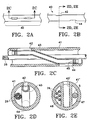
- This embodiment may be constructed in a variety of ways, including, for example, the more specific embodiments provided collectively in Figures 2A-E.
- Figures 2C-D show an outer tubing (41) which coaxially surrounds an inner guidewire tubing (43).
- Guidewire tubing (43) is adhered to either side of the internal wall of the outer tubing (41). In one method, this may be accomplished by extending a shaped metallic mandrel within the interior lumen of the guidewire tubing (43) which forces that tubing against the wall of the outer tubing at preferred locations where ports are desired.
- the guidewire and outer tubings may melt together. This melt bond procedure may be performed simultaneously at each tubing interface or in series. After melting the tubings together and subsequent cooling, the mandrel is withdrawn.
- Apertures are formed at the melted tubing interfaces such as by laser or mechanical drilling (either before or after withdrawal of the mandrel).
- the ends of the inner tubing on the outer border of each formed port may be blocked, such as by filling the cross section of tubing in that region with adhesive or further melting a plug of similar material in that region (45), as would be apparent to one of ordinary skill.
- FIG. 2C-D allows for the required guidewire tracking lumen and also maintains at least one additional, longitudinal conduit through the region of the guidewire tracking lumen between the guidewire tubing (43) and the outer tubing (41). This allows for the passage of electrode leads (26), and may also provide for additional elements to communicate therethrough, such as for slideably advancing stylets therethrough or for suction/fluid delivery, as will be discussed in more detail below.
- Figure 2E shows a further embodiment for intermediate guidewire tracking member (40), wherein a multi-lumen extruded tubing (41') includes a central lumen as the guidewire lumen (43').
- Guidewire lumen (43') is bordered on either side by a first lumen, shown as electrode lead lumen (46), and a second lumen (47) which has varied additional functionality as just described for Figures 2C-D, including suctioning, fluid delivery, and passage of stylets for remote manipulation of distal catheter regions.
- first and second intermediate guidewire ports (42,44) may be formed at the same longitudinal position along the elongate catheter body, rather than in staggered proximal-distal arrangement.
- a guidewire may slideably engage the tracking member in a perpendicular plane to the longitudinal axis of the elongate body.
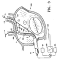
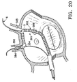
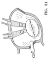
- FIG 3 further shows tissue ablation device assembly (1) in use during the formation of a long linear lesion between adjacent pulmonary vein ostia in a left atrium (80).
- the ablation catheter (2) is shown with the distal and intermediate guidewire tracking members (30,40) in the left and right superior pulmonary vein ostia (83,84), respectively.
- This particular arrangement is provided merely for the purpose of illustrating the operation of the anchoring mechanisms which are beneficially provided with the long linear lesioning device of the current invention.
- the proximal end portion (11) of the elongate body is further shown throughout Figures 3-9C in schematic view in order to illustrate engagement of the ablation element to ablation actuator (90), which is further schematically shown coupled to a return electrode (98), and also to signal recording device (91) and pacing device (93).
- Figure 3 initially shows two guidewires (3,4) which have been previously placed within the left and right pulmonary veins through their corresponding ostia (83,84) via transeptal sheath (6).
- This guidewire positioning may be accomplished by virtue of the steerability and resultant sub-selectability of the guidewires, themselves, within the atrial chamber.
- enhanced guiding systems such as that disclosed in U.S. Patent No. 5,575,766 to Swartz et al. may also be used to enhance the positioning of each guidewire into the desired vein ostia.
- Suitable guidewires for use in the present invention may vary, and previously known guidewire designs for placing other catheter device assemblies within the internal body spaces of the anatomy may be suitable for many applications.
- these guidewires have a metallic core, such as a stainless steel core or a superelastic metallic core, including a nickel-titanium core, which tapers distally and includes a radiopaque coil soldered, welded, or brazed over the tapered region.
- guidewires having an outer diameter of at least .014", including those having an outer diameter of approximately .018" or .032" may be suitable.
- the guidewires should also be either pre-shaped or shapeable in their distal tip region, and should also be torqueable and radiopaque (such as by the radiopaque coils just described), such that the device may be manipulated to sub-select the pulmonary vein ostia in the atrium under Xray fluoroscopy.
- the guidewires should be of suitable construction in order to provide sufficient support and steerability to position and guide the catheter assembly of the present invention into the pulmonary vein ostia within the atrium, as would be apparent to one of ordinary skill.
- Stop (13) is a radial enlargement which may be formed as a separate member over the underlying guidewire construction. Stop (13) may be made for example by soldering a ball of solder onto the outer surface of the underlying wire. Stop (13) may also be a polymeric member, such as that chosen from the group of polymers consisting of polyethylene, polyurethane, polyvinyl chloride, or the like. Furthermore, an enlarged region of adhesive such as a cyanoacrylate adhesive may be formed over the guidewire to form the stop (13).
- each of the guidewires (3,4) provides an initial platform over which a region of the ablation catheter assembly engaged with the guidewire may be positioned for anchoring at the respective vein ostia.
- Figure 3 shows the distal end portion of ablation catheter (2) after it has been advanced in a beneficial arrangement over the two guidewires (3,4).
- Each of the distal and intermediate guidewire tracking members (30,40) is coaxially engaged over guidewires (3,4), respectively, according to the following exemplary procedure.
- the guidewire proximal end portions may be "backloaded” into the respective distal and intermediate guidewire lumens of the catheter assembly. This is done by inserting the guidewire proximal end into for example the first distal guidewire port (32), and then retrogradedly advancing that guidewire proximal end rearwardly through the distal lumen and out the second distal guidewire port (34).
- the ablation catheter (2) is advanced over the guidewires (3,4) and into the region of their respective distal end portions in the internal body space.
- the distal end portion of ablation catheter (2) is advanced with respect to guidewire (3) until first distal guidewire port (32) confronts stop (13) within the first pulmonary vein, as shown in Figure 3.
- stop (13) positioned in a predetermined location along pulmonary vein with respect to ostium (83)
- the confronting engagement with distal guidewire tracking member (30) selectively positions the distal end (23) of the ablation element at a desired location within the ostium.
- Second distal guidewire port (34) is actually shown in Figure 3 to be located within the distal region of ablation element (20), and is positioned in the space between adjacent ablation electrodes.
- the region of coaxial coupling between guidewire (3) and the second distal guidewire port (34) may be positioned at or proximal to the pulmonary vein ostium, while a portion of the ablation element (20) may still be positioned within the ostium. It is believed that, for the purposes of forming efficacious conduction blocks in the regions of the left atrial pulmonary vein ostia, the long linear lesions should extend between and include at least the base of the pulmonary veins adjacent the ostia.
- proximal end (24) is anchored in the region of the adjacent right superior pulmonary vein ostium (84) by coaxially advancing intermediate guidewire tracking member (40) over guidewire (4).
- the ablation element is thereby adapted at least in part to substantially and firmly contact the length of tissue between the ablation element ends, including a linear region of tissue between the ostia and also portions of the ostia and veins stemming therefrom (at least at the first ostia).
- the adjacent tissue is ablated to form a long linear lesion between the predetermined anchoring locations at the ostia.
- a second ablation element (50) is shown variously throughout the figures to be positioned on the ablation catheter (2) proximally of the ablation element (20).
- Second ablation element (50) has its distal end anchored in the vicinity of the second predetermined anchoring location within the right superior pulmonary vein ostia via intermediate guidewire tracking member (40).
- a third anchoring or positioning means may be provided in order to position the proximal end of the second ablation element (50) at the third predetermined location to allow for another long linear lesion to be formed in a predetermined orientation and pattern along the atrial wall relative to the first lesion formed by the first ablation element.
- stylet (5) is adapted to function in this positioning role and is shown in shadowed view variously throughout the figures within the region of the second ablation element (50).
- the stylet (5) is engaged within a stylet lumen (not shown) within the elongate body and is adapted to remotely manipulate the positioning of the ablation catheter (2) at the third location.
- a suitable stylet may be a metal mandrel, such as a stainless steel mandrel or a superelastic metallic mandrel (for example, a nickel-titanium mandrel), which is slideably advanceable within a proximal lumen of the ablation catheter.
- the stylet may also be coated with a lubricious coating, such as with a fluoroethylpolymer (FEP), polytetrafluoroethylene (PTFE), paralene, or a hydrophilic polymeric coating, in order to facilitate slideable manipulation of the stylet within the stylet lumen of the elongate body.
- FEP fluoroethylpolymer
- PTFE polytetrafluoroethylene
- paralene or a hydrophilic polymeric coating
- the stylet should generally have a length adapted such that the distal end may be placed at the required region of the ablation catheter for in vivo positioning while the stylet proximal end extends externally of the body and the assembly to allow for remote manipulation by a physician user at its proximal extremity. Still further, the stylet should be preshaped in its distal end region, such that torsion on the proximal extremity of the stylet is adapted to controllably and translumenally manipulate the stylet tip in order to position the coaxially engaged catheter shaft along the atrial wall surface.
- the shaped stylet may be used to position the other end or portion at a second predetermined location.
- the first anchor provides a focus about which the stylet's manipulation may sweep the other portion of the ablation element, much like a compass may be used to sweep an arc or position a point about that arc at a predetermined location relative to the first location of the focus.
- Stylet (5) may also be adapted to advance further distally within the catheter, particularly during in vivo placement and anchoring of the distal guidewire tracking member at the first anchoring location.
- the region of the elongate body which houses the ablation element may be designed to be particularly flexible, such as for the purpose of conforming to the atrial wall anatomy. This flexibility may, however, sacrifice pushability and the ability to advance and remotely manipulate the distal end portion within the body space. Therefore, the variable positioning and use of the stylet within this distal catheter region may allow for the requisite stiffness to track, position, and anchor the ablation element when the stylet is advanced within that region, and allow also for flexible conformity of the ablation element to the atrial wall when the stylet is proximally withdrawn.
- stylet (5) is also shown in shadowed view variously throughout the rest of the figures and is intended to perform similar functions in the variations of those figures as those just described.
- a third anchor may also be provided on the device, such as proximally of the second ablation element (50) shown in Figures 1 and 3.
- a "proximal guidewire tracking member" (not shown) similar to the intermediate guidewire tracking member embodiments described may be provided as a third anchor adjacent to the proximal end of the second ablation element.
- the proximal guidewire tracking region may be positioned and anchored over the additional guidewire in yet a third ostium, such as the right inferior pulmonary vein ostium according to the device positioning shown in Figure 3.
- additional anchors and/or ablation elements may also be provided along the elongate body in combination with those just described.
- additional proximal guidewire tracking members may be provided, or additional stylets may slideably engage the interior lumens of the device elongate body, for the purpose of positioning other proximal portions of the elongate body within the anatomy.
- a plurality of ablation elements may be positioned between all adjacent pairs of vein ostia by use of a desirably positioned plurality of anchors along the elongate body which are adapted to simultaneously engage the regions of those individual ostia.
- the region between the inferior vein ostia need not be ablated or engaged with an anchored ablation element. This is because it is believed that a complete "box" pattern of conduction block which would otherwise result may create one or more new reentrant arrhythmia wavelets through the atrial wall tissue surrounding that box. Instead, it is believed preferable in many cases to create lesions which bridge these inferior ostia to the anatomical barrier of the mitral valve annulus.
- stylet (5) or a proximal guidewire tracking member as previously described may be used to position a proximal end of an ablation element, such as second ablation element (50) shown in Figure 3, in the vicinity of the mitral valve annulus.
- an ablation element such as second ablation element (50) shown in Figure 3
- a guidewire engaged with that member is placed anterograde from the atrium and into the ventricle through the mitral valve.
- the proximal guidewire tracking member is then advanced over the wire until positioned at the desired location along the mitral valve annulus.
- a long linear lesion may be thus formed between the anatomical structure of the superior or inferior vein ostia and the mitral valve annulus.
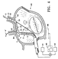
- Figure 4 shows a further variation of the use of stop members on the engaged guidewires through the distal and intermediate guidewire tracking members of the current invention.
- guidewire (4') includes a stop (14) which is positioned proximally of the second intermediate guidewire port (44).
- the wire distal end portion is preferably "front-loaded" into the intermediate guidewire tracking member prior to introducing the wire into the body. This is because only such front-loading would result in the arrangement shown ("back-loading" of the guidewire would not be possible because the stop would block the tracking member from being positioned distally thereover).
- guidewire (4') may be used to push the proximal end (24) of the ablation element (20) distally against the engaged pulmonary vein ostia in order to more firmly anchor the proximal end (24) into that ostium.
- a guidewire region which includes or is located proximal of the stop may also have a shape in order to enhance this "pushing" function of the proximal stop variation.
- a sweeping or discrete bend in the wire proximally of the stop may enhance directing the vector of force along the wire's length transversely from the wire's entrance into the left atrium through the guiding catheter in the fossa ovalis and toward the posterior atrial wall in the region of the pulmonary vein ostia.
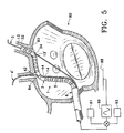
- Figure 5 shows still a further variation incorporating the use of stop members on the guidewires to provide a means for forcing the engaged region of the ablation catheter against the tissue adjacent the vein ostia.
- both guidewires (3,4') have stop members (13',14), respectively, which are positioned proximally of the respectively engaged distal and intermediate guidewire tracking members (30,40).
- this assembly must be entirely "pre-loaded” with the distal ends of the guidewires inserted into the respective lumens of the respective tracking members.
- the assembly of this variation benefits from the ability to have force applied distally toward the desired anchoring locations in the adjacent pulmonary vein ostia via the proximally positioned stops on the guidewires.
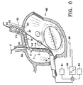
- Figure 6 show still a further variation of the ablation element anchoring feature of the current invention, wherein the distal end (23) of ablation element (20) is bordered by an expandable element (35) which is adapted to radially engage at least two opposite portions of the pulmonary vein wall within which the expandable element is positioned.
- the guidewire tracking methods for positioning the various regions of the ablation catheter relative to the pulmonary vein ostia may be substantially the same as for the previously described "guidewire stop" variations. However, once positioned, the device may be more substantially secured in that position due to the radial expansion of the expandable element.
- expandable element (35) is an inflatable balloon which is hydraulically coupled to a pressurizeable fluid source. Upon pressurization of the fluid source, fluid is forced into the balloon to hydraulically expand its diameter at least until circumferentially engaging a portion of the vein wall.
- regions of the ablation catheter proximal to the balloon must provide a hydraulic fluid conduit such as an isolated inflation lumen that is coupled both to the balloon and also to the pressurizeable inflation source through the proximal coupler, as would be apparent to one of ordinary skill.
- the inflation source includes a source of radiopaque fluid which is adapted for visualizing inflation characteristics of the balloon upon Xray fluoroscopy.
- the balloon may be a relatively elastic, expandable tubing, such as a latex rubber or silicone tubing, or may be a relatively less compliant, folded balloon, such as a polyethylene, polyolefin copolymer, polyvinyl chloride, or nylon balloon, which has relatively slight, controlled compliance during pressurization.
- the balloon may have predetermined sizing based substantially upon volume of fluid used to inflate the balloon.
- a kit of ablation catheters with several predetermined sizes over a range of operating pressures may be provided in order to accommodate varying pulmonary vein anatomies and diameters.
- expandable element (35) may be radially expandable in ways other than hydraulic inflation of a balloon.
- a radially expandable cage may provide enough radial force on the vein wall to provide a sufficient anchor to that region of the ablation assembly.
- Other expandable members may also be suitable, such as those described in U.S. Patent No. 5,509,900 to Kirkman.
- expandable element (35) may also be adapted to preferentially expand in one radial direction versus another, such that the central axis of the underlying elongate body is biased to one side of the expanded element's diameter.
- This may for example be particularly desirable for forcing the most distal electrodes of the ablation element, which are adjacent the expandable element, against a particular portion of the pulmonary vein wall. Without such radial bias, it is believed that a lack of intimal wall contact may result in regions of the elongate body adjacent to the expandable element.
- the bias forces the adjacent region of the ablation element against the interior wall of the vessel which is between the anchors, thereby resulting in a long continuous lesion that extends with continuity up into the engaged vein.
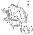
- Figure 7 shows a further variation of the intermediate guidewire tracking member (40) which forms the anchor adjacent the proximal end (24) of the ablation element (20).
- the intermediate guidewire tracking member (40) includes an intermediate lumen which has a second intermediate guidewire port (not shown) which is located at or near the proximal end portions of the ablation catheter (2), such as at the proximal coupler (not shown). It is believed that this elongated coaxial arrangement of at least one of the guidewire tracking members may provide a benefit in reducing the number of devices which are exposed to the internal bores of the delivery device and also within the atrium. Similarly, the need to include means for the intermediate guidewire to traverse the diameter of the elongate body as described by reference to Figures 2A-E above is removed by this variation.
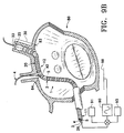
- Figure 8 shows the distal end portion of ablation catheter (2) to be branched such that intermediate guidewire tracking member (40) includes an intermediate leg (47).
- the intermediate leg (47) provides a platform upon which additional electrodes (26) may be positioned to allow the proximal end of ablation element (20) to extend further into the second pulmonary vein ostium in which the intermediate guidewire tracking member (40) is anchored.
- Intermediate leg (47) may be constructed according to a variety of methods.
- a first polymeric tubing includes proximal shaft (11) and has a port formed through its outer wall and into a lumen formed by that tubing.
- a second tubing of similar material is placed snugly over a mandrel, such as a teflon coated stainless steel mandrel, which mandrel is inserted into the lumen through the port until the end of the second tubing circumferentially engages the port.
- the port and the engaging end of the second tubing (which is actually a second port) are adapted with predetermined geometries sufficient to mate their orifices to form a substantial seal at their interface.
- the engaged region of tubings is next placed next to an inductive heating source which is energized to sufficiently heat the adjacent region of mandrel in order to melt the region of the second tubing and thereby splice the tubings together in that region.
- an additional step may be to heatshrink a third piece of tubing over the two-tubing adaption prior to removal of the mandrel in order to provide some additional structural integrity to the adaption.
- the second tubing may be either the intermediate leg (47) or the distal end portion of the ablation catheter (2).
- An additional method of forming the branched intermediate and distal end portions of the ablation catheter of the current invention may be as follows.
- An extruded polymeric tubing having two round lumens separated by a central wall, or a "dual lumen" extrusion, is cut to a predetermined length.
- One end of the dual lumen extrusion is cut along the tubing's longitudinal axis through the central wall to create the bifurcation.
- the resulting branched tubings in this alternative method may then be "post-processed" to prepare the tubings for adapting the electrode elements along their length, as would be apparent to one of ordinary skill.
- the flat surfaces created by the formation of the branched tubings just described may be rounded such as by grinding or by melting the tubing within pieces of coaxial heat shrink tubing while mandrels are placed within the tubings (the heat shrink tubing of this variation would be removed after heat shrinking, and would be a dissimilar material such as a teflon heat shrink tubing or a polyimide heatshrink tubing).
- the resulting flat surfaces of the branched tubings may be desired, particularly since these surface would be naturally oriented to confront the tissue within and between the pulmonary vein ostia.
- the ablation element such as a plurality of electrode sub-elements may be placed only onto the flat surfaces created and would thus be substantially isolated to the elongate region of tissue contact along the length of the ablation element.
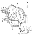
- FIGS 9A-C collectively portray a further variation of the distal guidewire tracking member as an anchoring means, which is shown in combination with the intermediate guidewire tracking member variation shown initially in Figure 7.
- neither of the guidewire tracking members has a second guidewire port located proximally of the first relative guidewire port in the region of the distal end portion of the ablation catheter.
- each of the distal and intermediate lumens extends proximally along the length of the elongate body of the catheter and terminates in a port (not shown) on the proximal end portion (11) of the catheter.
- a stop may be provided on the guidewire engaged within the distal lumen of the distal guidewire tracking member, such as shown at stop (13') on guidewire (3) in Figure 9A
- Figures 9B-C however show a different anchoring emodiment in the distal anchor than that shown in Figure 9A.
- the Figure 9B-C variation combines the catheter-guidewire tracking design of Figure 9A with an expandable member anchoring mechanism at the distal device end, such as that shown previously in Figure 6.
- the variation of Figures 9B-C allows for the guidewire (3) to be withdrawn proximally from the portion of the guidewire lumen which extends between the first distal guidewire port (33) and the second distal guidewire port (34).
- the present invention has been heretofore shown and described by reference to particular variations of anchors at distal and intermediate catheter regions adjacent to two opposite ends of an ablation element, respectively. These anchoring variations are adapted to allow for substantial tissue contact between the ablation element ends for creating a continuous, long linear lesion. However, it is further contemplated that the region of the ablation element itself may be additionally adapted to increase tissue contact along its length between the anchors at adjacent pulmonary vein ostia.
- the ablation element may include at least one ablation element anchor along its length which is adapted to engage the tissue adjacent to the element.
- the ablation element anchor may be a suctioning means which includes at least one port in fluid communication with a vacuum source via a suction/air lumen extending through the body of the ablation catheter.
- Figures 10A-E show various levels of detail of a similar ablation catheter variation as that shown in Figure 7 for purpose of illustration, and show a more detailed mode which includes a suctioning anchor means in the region of the ablation element (120).
- the ablation element (120) includes a portion of a fluid lumen (127) which communicates exteriorly of the catheter device in the region of the ablation element through a plurality of fluid ports (128). These ports are positioned such that they face the tissue adjacent to the ablation element when the distal and intermediate guidewire tracking members (130,140) are anchored in adjacent pulmonary vein ostia.
- Fluid lumen (127) is adapted to couple to a vacuum source via a proximal coupler (not shown), in order to provide a suction force at the fluid ports (128) during ablation such that the ablation element is firmly in tissue contact during the ablation.
- a proximal coupler not shown
- an internal seal 129
- Seal (129) is located internally of fluid lumen (127) and distally therein relative to the most distal of fluid ports (128).
- This seal (129) provides one means for allowing for fluid isolation between the suction lumen in the region of the ablation element and the guidewire tracking member and its corresponding lumen.
- Various methods may be used for creating the seal (129), such as for example delivering a bolus of high viscosity or quick curing adhesive to the desired interlumenal location for the seal, or for example, by melting a plug of material within that lumen, or a combination of these or other methods.
- the region of the catheter containing the ablation element, particularly between the ablation element's ends may also be preshaped in a manner such that the ablation element has a bias into the tissue between the predetermined locations at which the ablation element ends are anchored.
- This bias may be heat set into the polymeric tubing making up the elongate body in the region of the ablation element, or may otherwise be formed, such as for example by providing a pre-shaped reinforcing member at that region of the elongate body.
- Such a pre-shape may be provided, as a further example, by means of the stylet (5) shown variously throughout the figures. In this mode, the stylet is adapted to advance distally into the region of the ablation element an to impart a biased shape to that region.
- Both the suctioning means described, as well as the preshaped bias means are designed to take advantage of a natural orienting feature of an ablation catheter according to the anchoring mechanisms of the present invention.
- the anchors used in a particular variation are guidewire tracking members adapted to anchor in adjacent vessel ostia, such as in the variations heretofore described, the two guidewire tracking members will generally tend to take a natural, predictable orientation along the engaged guidewire axis.
- the ablation element extending between those oriented anchors will also generally tend to orient in a predictable fashion when engaged to the tissue in order to accommodate the preshaped bias variation and the fluid port/suction variations just described for the ablation element of the current invention.
- FIG 10F shows a further variation of the device assembly shown in Figures 10A-E, wherein the ablation element (220) has been modified.
- An energy sink (270) is provided in this variation which, rather than being disposed in a fixed orientation on the external surface of the elongate body, is instead slideably engaged within a lumen (not shown) in communication with the plurality of fluid ports (228).
- the energy sink (270) may be any of the alternative energy sources or other ablation technologies introduced above, such as an RF electrode, microwave antenna, cryoblation probe, fiber optic laser source, or ultrasound source.
- the ablation means of this variation is adapted to ablate through the ports as it is moved to traverse across those ports while actuated for ablation.
- each of a plurality of ports is slideably engaged to a needle which is adapted to advance through the port and into the adjacent tissue as an anchor.
- the particular geometry and dimensions of the electrodes along the length of the ablation element (20) may effect the overall ablation characteristics, and a variety of arrangements may be suited for particular applications without departing from the scope of the present invention.
- these electrodes generally may be made of electrically conducting material, such as copper alloy, platinum, or gold, and may be wrapped about the flexible body of the device.
- the electrodes should generally be designed to provide a suitable contact area with the tissue wall adjacent to the ablation element when anchored in place.
- the length and spacing of the electrodes may be particularly adapted to accommodate the ablation energy to be used.
- This combination is desired in order to optimize the creation of a continuous, long linear pattern of ablation which includes the regions between the electrodes.
- gaps in such lesions may provide a route for reentrant atrial arrhythmia which might otherwise be blocked with a suitably contiguous lesion.
- the desired lesions should be transmural, or from one side of the atrial wall to the other, in order to effectively block aberrant reentrant signals from bridging across the lesion and resulting in arrhythmia.
- One electrode construction which is believed to be particularly well suited for use in ablating long linear lesions in the left atrial wall is as follows.
- a plurality of electrodes is provided along the ablation element, each electrode being constructed of a circumferentially coiled metallic wire, preferably a platinum wire.
- Each coiled electrode has a width that preferably ranges from 5 to 8 millimeters, and each adjacent pair of electrodes is preferably spaced 1 to 2 centimeters apart. It is believed that simultaneously energizing a plurality of electrodes according to this construction at a frequency of 500 KHz and at a power level ranging from 50-100 W will form a long linear lesion in atrial wall tissue sufficient to form a conduction block in many cases.
- the number of electrodes positioned along the ablation element according to these parameters may vary depending upon the overall desired ablation element length in order to form a particular long linear lesion.
- signal recording device (91) may be coupled to the electrodes of the ablation element for the purpose of monitoring for arrhytmias prior to, during, or after ablation is performed with those same electrodes, as would be apparent to one of ordinary skill.
- This recording device is preferably used after anchoring the ablation element at the desired region for forming the desired long linear lesion.
- Such recording of atrial electrograms allows a treating physician to: (1) confirm arrhythmia in the region of anchored ablation element; (2) define the anatomical limits of the atrial tissue along the ablation element length (when monitored at each electrode, such as extending outwardly along the wall of the pulmonary veins); (3) to assess the closeness of the ablation element to the mitral valve annulus (both atrial and ventricular electrical signals appear at the respective leads when at the annulus); and (4) to monitor conduction block after performing an ablation. It is believed that, by adequately securing and anchoring the ablation element to the ablation region before, during, and after ablation, accurate recording and subsequent analysis of the treatment may be achieved in a beating heart.
- a suitable recording device for use with the present invention is the "CardioLab”TM system by Pruka Engineering Incorporated ("PEI”), located in Houston, TX.
- PEI Pruka Engineering Incorporated
- pacing device selectively allows artificial stimulation to the region of ablation in order to assess the conduction block ideally formed.
- the ablated tissue is preferably dead and non-conductive and actuating the electrodes along that region via a pacing rhythm should not result in significant atrial wall conduction or wall motion response.
- pacing may be achieved and conduction block of a known signal may be assessed.
- a suitable pacing device for use with the present invention is the programmed pacing stimulator made by Bloom, Inc..
- 1-20mA of current in a square wave with a pulse width of 1 to 10msec may be sufficient to induce arrhythmias to monitor the region of conduction block, or to pace map, or to measure pacing threshold of the targetted tissue pre- or post-ablation.
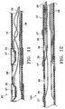
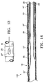
- Figures 11-14 provide more detailed views of variations for the ablation element as it is positioned on the ablation catheter.
- Figure 11 shows a plurality of electrodes (25) which are coupled to electrode leads (26), respectively, which are shown to extend proximally along the length of the catheter elongate body (10) where they are then engaged to at least one electrical coupler (not shown).
- Ablation element (20) may also include temperature monitoring elements, as are also shown in Figure 11 at thermistors (27).
- thermistors which may also be thermocouples
- Each of thermistors (27) is shown in Figure I 1 to be positioned in the vicinity of one of the electrodes (25) and is also coupled to one of temperature monitoring leads (29).
- thermocouples (27') instead of thermistors, are shown in the vicinity of the electrodes (25). More detail regarding the particular size, material, dimensions, and methods of constructing the electrode and temperature monitoring elements onto a catheter as just described may be found by reference to U.S. Patent No. 5,582,609 to Swanson ct al., which has been previously cited.
- thermocouples (27') between adjacent electrodes (25) along the ablation element (121).
- Ablation actuator (90) in the Figure 15A variation includes a current source (92) for supplying an RF current, a monitoring circuit (94), and a control circuit (96).
- the current source (92) is coupled to the ablation element (not shown) via the electrode leads in electrical coupler (51), and is also coupled to the ground patch (98).
- Monitoring circuit (94) is coupled to the thermistor leads in electrical coupler (51), and also to control circuit (96).
- Control circuit (96) is in turn coupled to both the monitoring circuit (94), and also to the current source (92) in order to adjust the output level of current driving the electrodes based upon the relationship between the monitored temperature and a predetermined temperature set-point.
- the feedback control circuit just described is therefore based upon comparing the measured, real-time temperature of the ablation region against values known to indicate ablation progress.
- a monitored temperature may for example signal the completion of ablation and therefore trigger cessation of energy delivery.
- such values may indicate the quality of tissue contact, which information may be used in the control circuit to adjust the drive current to the region at issue.
- a particular set-point may be predetermined based upon known empirical values, or may be patient dependent, as would be apparent to one of ordinary skill.
- the electrical parameters of the RF ablation drive circuit may be monitored in order to provide suitable feedback control.
- output voltage, output current, output power, impedance, or reflected power, or change or time rate of change of these parameters may be monitored and used in one or a series of feedback control algorithms.
- the real-time value of such monitored parameters have been observed to characterize the progress of some ablation procedures, and have also been used in control circuits for real-time feedback control of ablation drive current.
- Each individual electrode of the plurality of electrodes in the ablation element may also be individually controlled in a control system, such as in a multiplexed system.
- a control system such as in a multiplexed system.
- One example of a feedback control system which is believed to be suited for such feedback control of the ablation elements provided with the present invention is described in WO 96/00036 to Panescu et al. Further examples of feedback control systems which may be adapted for use in the present invention according to one of ordinary skill based upon this disclosure are provided in US Patent No. 5,496,312 to Klicek; US Patent No. 5,437,664 to Cohen et al.: and WO 93/20770 to Strul.
- Figures 16-21 show the device assembly of the current invention in various steps during the completion of an overall atrial fibrillation treatment procedure, wherein a box configuration of conduction block is created around the region of the pulmonary vein ostia.
- an atrial lesioning catheter device assembly similar to that shown in Figure 5 is shown, for purposes of illustration, in various positions within a sectioned left atrium during sequential lesion formation between various predetermined pairs of pulmonary vein ostia.
- FIG 16 shows tissue ablation device assembly (301) after performing a first long linear lesion ablation procedure with the ablation element (320) of ablation catheter (302) positioned in a first position between the left and right superior pulmonary vein ostia (383,384) (first position not shown in this figure).
- ablation catheter (302) is shown repositioned in a second position between the left superior and inferior pulmonary vein ostia for performing a long linear lesion ablation procedure between that pair of adjacent vein ostia.
- Figure 17 shows the ablation catheter (302) in the left atrium after performing a second long linear lesion ablation procedure according to Figure 16, wherein the ablation element (320) is repositioned to a third position where its ends are anchored in the right superior and inferior vein ostia (384,385). Subsequent to performing this third linear ablation, an open ended box of lesions results between all adjacent pairs of vein ostia, but between the inferior vein ostia. This result may sufficiently treat some atrial reentrant fibrillation sequelae, as may any of the other interim results subsequent to each ablation lesioning step described for this procedure.
- Figures 18 and 19 therefore show sequential steps in forming a pair of lesions between the inferior pulmonary vein ostia and the region of tissue adjacent to the mitral valve annulus. More particularly. Figures 18 and 19 provide a schematic representation of the intracardiac placement of two monopolar electrodes that are combined in a bipolar cardiac ablation arrangement which is adapted to form ablation lesions between the inferior pulmonary vein ostia and adjacent regions of the mitral valve annulus.
- a first monopolar ablation electrode element (392) is shown positioned adjacent to the left inferior pulmonary vein ostia (386).
- this electrode may take many suitable forms in this application regarding its incorporation onto various catheter platforms, and is therefore represented schematically.
- the electrode may be at least one of the electrodes along the length of an ablation element as provided in the previous variations of the invention.
- the electrode may be at the end of an ablation element adjacent to the catheter's most distal end, such as the electrode shown between guidewire ports (332) and (334) in Figures 16 and 17.
- the electrode may be positioned within the inferior pulmonary vein ostium as would be apparent to one of ordinary skill according to the teachings of the variations above.
- a second ablation electrode element (395) is also shown in shadowed view in Figure 18 positioned within the coronary sinus (396) and is positioned along that lumen such that it is adjacent to the first electrode element (392).
- this electrode may comprise one of several known electrode configurations and be sufficient for the purposes of this bipolar ablation step, hence the schematic representation in the Figure.
- the second ablation electrode element (395) is positioned in the coronary sinus as follows. Initially, a guiding catheter is introduced into the right atrium either via the superior or the inferior vena cavae according to known methods (and according to some of the same methods described in more detail above). Next, the device is introduced through the guiding catheter and into the coronary sinus through its ostium in the right atrium, which may be accomplished by tracking the second electrode carrying device (394) over a steerable guidewire which has previously sub-selected the coronary sinus distally of the guiding catheter. Or, in the alternative, the guiding catheter or a second guiding catheter within the original guiding catheter may be shaped and otherwise adapted to engage the coronary sinus ostium along the right atrial wall and thereby provide a lumenal conduit into that vessel.
- the second electrode (394) may be positioned relative to the first electrode using a variety of techniques.
- the electrical potential between the two electrodes may provide a measure of their relative distance from each other. This measure may provide a telling inflection point as the second electrode is advanced through the coronary sinus and across the position closest to the stationary, anchored first electrode.
- the first and second electrodes are each sufficiently radiopaque such that their relative distance from each other is easy to visualize via Xray fluoroscopy.
- an electrical signal transmitting therebetween serves to ablate the atrial wall tissue therebetween, as would be apparent to one of ordinary skill.
- Figure 19 shows a similar schematic view of first and second electrode devices as that shown in Figure 18, although showing the devices in a second position wherein they are collectively adapted to ablate a long linear lesion between the right pulmonary vein ostium (385) and an adjacent region of the mitral valve annulus (388).
- a long linear lesion is shown between the left pulmonary vein ostium (386) and an adjacent region of the mitral valve annulus (387) subsequent to its formation according to the device positioning of Figure 18.
- the lesioned "box” is thus completed by forming long linear lesions between and connecting the inferior pulmonary veins with the region of the mitral valve annulus.
- Figure 20 shows further a device assembly of the current invention in a single positioning event during an atrial fibrillation treatment procedure, wherein at least a portion of a conduction block is created around the pulmonary vein ostia and the mitral valve annulus in an assembly shown in a similar, reciprocal image as that view shown in Figure 7.
- tissue ablation device assembly (301) is used to create multiple long linear lesions with various adjacently positioned ablation elements along its body and.
- an ablation element (320) has each of two ends anchored in the two adjacent superior vein ostia (383,384).
- a second ablation element (325) is provided proximally of the anchor engaged to left superior ostium (383) and is anchored distally by that same anchor and more proximally is positioned against the wall via a shaped stylet (305).
- shaped stylet (305) is adapted to impart a shape to the catheter shaft in the region of the second ablation element such that the shaped region of the ablation element substantially conforms to the tissue of the adjacent atrial wall.
- stylet (305) adapts the region of the second ablation element to traverse the left inferior pulmonary vein ostia (386) to the region of the coronary sinus so as to engage the mitral valve annulus. In this manner, a single continuous long linear lesion is created.
- a guidewire may be advanced antegrade from the left atrium and through the mitral valve into the left ventricle.
- a rail is provided into the region of the mitral valve such that a correspondingly engaged guidewire tracking member on the tissue ablation catheter assembly according to the invention may be placed through the valve to anchor the ablation element against the mitral valve annulus.
- a guiding catheter tip is advanced into the left atrium through the mitral valve. It is also contemplated that that guiding catheter tip region may provide an additional ablation element to assist in completing the inferior leg of the barrier-to-barrier conduction block described by ablating a region between the inferior vein ostia and the mitral valve annulus.
- Figure 21 shows a completed "box" of long linear lesions formed according to the ablation catheter variations shown and described above, and particularly by reference to the sequential long linear lesioning methods shown and described with reference to Figures 16-19.
- the initial placement of the ablation catheter assembly into the left atrium may be achieved using known access procedures according to one of ordinary skill.
- these procedures access the left atrium either transeptally from the right atrium through the fossa ovalis in the intra-atrial septal wall, or retrogradedly from the left ventricle and through the mitral valve (as introduced briefly above).
- the embodiments shown herein in the figures and described above have portrayed use of the present invention through a transeptal sheath approach for the purpose of consistent illustration.
- the device variations described are considered to be adapted or easily modified according to one of ordinary skill for use in the retrograde arterial approach from the ventricle into the left atrium.
- a brief overview of one transeptal left atrial access procedure through the fossa ovalis is herein described for the purpose of providing a thorough understanding of an acceptable access method.
- the right atrium is accessed with a guiding catheter or sheath through either the inferior or superior vena cava, which initially requires cannulation with an introducer sheath such as through the well known "Seldinger” technique.
- Suitable guiding catheters for use in this procedure are also well known, but generally range from 7 to 12 French, preferably 8 to 12 French, and include shaped, radiopaque tips and torqueability for the purpose of steering and directing the catheter to the desired remote in vivo locations under Xray fluoroscopy.
- at least one large lumen is provided in the guiding catheter for the purpose of providing a tubular conduit for the delivery of various object devices for treatment once properly located.
- a guidewire such as a .032" diameter guidewire is also provided coaxially within the guiding catheter lumen in a telescoping arrangement, also for aiding the directing the guiding catheter to the target site.
- the guiding catheter is directed toward the fossa ovalis, and is advanced through that septal opening to finally cannulate the left atrium and provide lumenal access into that body space to direct object treatment or diagnostic devices thereto.
- the access through the fossa ovalis may be achieved by advancing a "Brockenbrough" needle or trocar through a dilator, which assembly is against the fossa ovalis through the guiding catheter.
- the needle, dilator, and guiding catheter are then advanced through the fossa ovalis, after which the needle and dilator are withdrawn to leave the guiding catheter in place.
- patients are known to differ in their anatomical make-up in the region of the pulmonary vein ostia. More particularly, Jafs et al. in a scientific abstract entitled, "Biatrial Dimensions Relevant to Catheter Ablation", North American Society of Pacing and Electrophysiology, 17th Annual Scientific Sessions Abstract Form, has previously disclosed finite ranges of distances between the various pairs of adjacent pulmonary vein ostia among human left atria.
- the range of distances between the superior pulmonary vein ostia is believed to be 31 to 55 millimeters (mean of 43 .+-.8 millimeters); and the range of distances between the superior and inferior pulmonary vein ostia is 25 to 46 millimeters (mean of 38 .+-.7 millimeters).
- kits of ablation catheter device assemblies may be required which includes various lengths of ablation elements between anchors.
- providing a kit with available ablation elements having lengths ranging from approximately 15 millimeters to approximately 70 millimeters, and preferably ranging from approximately 25 millimeters to approximately 55 millimeters may provide a suitable range to choose from in order to treat most patients.
- quantitative pulmonary angiography and/or transesophageal echocardiography may provide sufficient diagnostic tools for measuring a patients inter-pulmonary vein ostia distances prior to long linear lesioning treatment.
- the kit will also typically include appropriate packaging for the individual devices and instructions for operation and use.
- patients receiving the long linear lesioning treatment described for the apparatus of present invention may benefit from the administration of various anticoagulants such as Cumidin and/or Heparin.
- a tissue ablation device assembly comprises an elongate body having a proximal end portion and a distal end portion that includes an elongate ablation element with a length and which also includes at least one anchor along the length of the ablation element that is adapted to secure the ablation element to a region of tissue adjacent to said anchor.
Abstract
Description
In addition, none of the cited references discloses a catheter device that provides a multirail guidewire tracking capability at various positions along the catheter length.
Claims (26)
- An apparatus for treating atrial arrhythmia in a patient, comprising:an ablation element (20) constructed to couple to an ablation actuator (90) and to be positioned along a region of tissue at a location where a pulmonary vein extends from an atrium in order to ablate the tissue;an anchor coupled to the ablation element (20) and constructed to be positioned within the pulmonary vein to engage a pulmonary vein wall at an anchoring position along the pulmonary vein such that the ablation element (20) is substantially secured along the location; andan elongate body (10) with a proximal end portion (11) and a distal end portion (12) adapted to deliver the anchor to the anchoring position and the ablation element (20) along the location, and further with a distal guidewire tracking member (30) and an intermediate guidewire tracking member (40) for moveably engaging and tracking over a distal guidewire (3) and a proximal guidewire (4), respectively, when the distal and proximal guidewires are positioned in first and second pulmonary veins, respectively.
- The apparatus of claim 1, wherein the anchor comprises an expandable element (35) that is constructed to expand to a sufficient outer diameter to engage a wall of the pulmonary vein at the anchoring position.
- The apparatus of claim 2, wherein the expandable element (35) comprises an inflatable balloon.
- The apparatus of claim 2, wherein the expandable element (35) comprises a central axis that is substantially aligned with and extends along a central longitudinal axis of the pulmonary vein when the expandable element (35) is anchored at the anchoring position and the ablation element (20) extends proximally from the expandable element (35) off center from the central axis.
- The apparatus of claim 2, further comprising a perfusion passageway consisting of a first distal guidewire port (32) and a second distal guidewire port (34) formed in the distal guidewire tracking member (30), the perfusion passageway (30, 32, 34) being constructed to allow a volume of blood to flow from a region distally of the expandable element (35), along the pulmonary vein across the expandable element (35) and proximally of the expandable element (35) when the expandable element (35) is expanded and engaged to the wall of the pulmonary vein at the anchoring position.
- The apparatus of claim 5, wherein the perfusion passageway (30, 32, 34) comprises a perfusion lumen extending between the first distal guidewire port (32) along the distal end portion (23) and the second distal guidewire port (34) located proximally of the first distal guidewire port (32) along the distal end portion (23), and wherein the expandable element (35) is located along the distal end portion (23) between the first distal guidewire port (32) and the second distal guidewire port (34).
- The apparatus of claim 1, wherein the anchor and ablation element (20) are both located along the distal end portion (12) of the elongate body (10).
- The apparatus of claim 1, wherein the ablation element (20) is located at least in part proximally of the anchor with respect to the elongate body (10).
- The apparatus of claim 1, wherein the ablation element (20) has a length and is constructed to ablatively couple to a region of tissue that extends from the location and along a wall of the atrium.
- The apparatus of claim 1, wherein the ablation element (20) is moveable relative to the anchor so as to be repositioned at multiple positions along a circumferential path that corresponds to a circumferential region of tissue at the location.
- The apparatus of claim 1, further comprising a stylet (5) wherein the ablation element (20) is located along the stylet (5) and the stylet (5) is adapted to position the ablation element (20) along the location for ablation.
- The apparatus of claim 1, wherein the ablation element (20) comprises an electrical ablation element with at least one electrode (25) which is adapted to couple to an electrical current source (92).
- The apparatus of claim 12, wherein the ablation element (20) comprises a plurality of said electrodes (25) which are spaced along the distal end portion to form a linear ablation element.
- The apparatus of claim 1, wherein the ablation element (20) comprises any of a cryoblation element, a light emitting ablation element, a microwave ablation element, a fluid ablation element, and a thermal ablation element.
- The apparatus of claim 1, further comprising an ablation actuating assembly consisting of an ablation actuator (90), a signal recording device (91) and a pacing device (93), the ablation actuating assembly (90, 91, 93) being constructed to couple to and actuate the ablation element (20).
- The apparatus of claim 1, wherein the elongate body (10) has a longitudinal axis, wherein said ablation element (20) has a length located along the longitudinal axis of the elongate body (10), and wherein the anchor is located along the elongate body (10) generally distal to the ablation element (20) relative to the longitudinal axis.
- The apparatus of claim 1 wherein the anchor is a first anchor constructed to engage the first pulmonary vein wall at a first anchoring position, and the apparatus further comprises:a second anchor constructed to be positioned within the second pulmonary vein to engage a pulmonary vein wall at a second anchoring position along the second pulmonary vein such that the ablation element (20) is substantially secured along the location.
- The apparatus of claim 17, wherein the first anchor is comprised of:a first guidewire (3) positionable within said first pulmonary vein; andthe distal guidewire tracking member (30) .
- The apparatus of claim 18, wherein:the apparatus further comprises a longitudinal axis;the distal guidewire tracking member (30) comprises a first guidewire passageway extending along the elongate body between a first distal port (32) located along the distal end portion (23) and a first proximal port (34) located along the elongate body proximally of the first distal port, the first guidewire passageway being adapted to slideably receive the distal guidewire (3) through the first distal and proximal ports; andthe ablation member (20) is located at least in part along the distal end portion (12) of the elongate body.
- The apparatus of claim 18, wherein the second anchor is comprised of:a second guidewire (4) positionable within a second pulmonary vein; andthe intermediate guidewire tracking member (40) .
- The apparatus of claim 20, wherein:the apparatus further comprises a longitudinal axis;the distal guidewire tracking member (30) comprises a first guidewire passageway extending along the elongate body between a first distal port (32) located along the distal end portion (23) and a first proximal port (34) located along the elongate body proximally of the first distal port, the first guidewire passageway being adapted to slideably receive the first guidewire (3) through the first distal and proximal ports; andthe intermediate guidewire tracking member (40) comprises a second guidewire passageway extending along the elongate body between a second distal port (42) located proximally of the first distal port (32) along the elongate body and a second proximal port (44) located proximally of the second distal port along the elongate body, the second guidewire passageway being adapted to slideably receive the second guidewire (4) through the second distal and proximal ports.
- The apparatus of claim 21, wherein the ablation element (20) is located along the distal end portion between the first and second distal ports (32, 42).
- The apparatus of claim 17, wherein the first anchor comprises an anchoring region adapted to have a shape positionable within the first pulmonary vein.
- The assembly of claim 23, wherein the anchoring region is a first anchoring region and the second anchor comprises a second anchoring region adapted to have a second shape positionable within the second pulmonary vein.
- The apparatus of claim 17, wherein at least one of said first and second anchors further comprises an expandable member (35) adapted to couple to an expansion actuator and to expand to engage a pulmonary vein wall of the first or second pulmonary vein.
- The assembly of claim 17, wherein the ablation element (20) comprises at least one ablation electrode (25) adapted to couple to an electrical current source (92).
Applications Claiming Priority (3)
| Application Number | Priority Date | Filing Date | Title |
|---|---|---|---|
| US853861 | 1997-05-09 | ||
| US08/853,861 US5971983A (en) | 1997-05-09 | 1997-05-09 | Tissue ablation device and method of use |
| PCT/US1998/009554 WO1998049957A1 (en) | 1997-05-09 | 1998-05-11 | Cardiac tissue ablation device and method of use |
Publications (2)
| Publication Number | Publication Date |
|---|---|
| EP0975271A1 EP0975271A1 (en) | 2000-02-02 |
| EP0975271B1 true EP0975271B1 (en) | 2005-09-14 |
Family
ID=25317093
Family Applications (1)
| Application Number | Title | Priority Date | Filing Date |
|---|---|---|---|
| EP98922187A Expired - Lifetime EP0975271B1 (en) | 1997-05-09 | 1998-05-11 | Cardiac tissue ablation device |
Country Status (11)
| Country | Link |
|---|---|
| US (4) | US5971983A (en) |
| EP (1) | EP0975271B1 (en) |
| JP (2) | JP4113592B2 (en) |
| CN (1) | CN1181790C (en) |
| AT (1) | ATE304322T1 (en) |
| AU (1) | AU748537B2 (en) |
| BR (1) | BR9809258A (en) |
| CA (1) | CA2289639C (en) |
| DE (1) | DE69831562T2 (en) |
| IL (1) | IL132828A0 (en) |
| WO (1) | WO1998049957A1 (en) |
Families Citing this family (559)
| Publication number | Priority date | Publication date | Assignee | Title |
|---|---|---|---|---|
| US6161543A (en) | 1993-02-22 | 2000-12-19 | Epicor, Inc. | Methods of epicardial ablation for creating a lesion around the pulmonary veins |
| US6716216B1 (en) * | 1998-08-14 | 2004-04-06 | Kyphon Inc. | Systems and methods for treating vertebral bodies |
| IL115156A (en) * | 1994-09-06 | 2000-07-16 | Univ Georgia | Pharmaceutical compositions for the treatment of cancer comprising 1-(2-hydroxymethyl-1,3-dioxolan-4-yl) cytosines |
| US8025661B2 (en) | 1994-09-09 | 2011-09-27 | Cardiofocus, Inc. | Coaxial catheter instruments for ablation with radiant energy |
| US6423055B1 (en) | 1999-07-14 | 2002-07-23 | Cardiofocus, Inc. | Phototherapeutic wave guide apparatus |
| US6464700B1 (en) | 1994-10-07 | 2002-10-15 | Scimed Life Systems, Inc. | Loop structures for positioning a diagnostic or therapeutic element on the epicardium or other organ surface |
| US7175619B2 (en) * | 1994-10-07 | 2007-02-13 | Boston Scientific Scimed, Inc. | Loop structures for positioning a diagnostic or therapeutic element on the epicardium or other organ surface |
| US6071274A (en) | 1996-12-19 | 2000-06-06 | Ep Technologies, Inc. | Loop structures for supporting multiple electrode elements |
| US5814029A (en) * | 1994-11-03 | 1998-09-29 | Daig Corporation | Guiding introducer system for use in ablation and mapping procedures in the left ventricle |
| US6409722B1 (en) | 1998-07-07 | 2002-06-25 | Medtronic, Inc. | Apparatus and method for creating, maintaining, and controlling a virtual electrode used for the ablation of tissue |
| US5897553A (en) | 1995-11-02 | 1999-04-27 | Medtronic, Inc. | Ball point fluid-assisted electrocautery device |
| US6311692B1 (en) | 1996-10-22 | 2001-11-06 | Epicor, Inc. | Apparatus and method for diagnosis and therapy of electrophysiological disease |
| US6805128B1 (en) | 1996-10-22 | 2004-10-19 | Epicor Medical, Inc. | Apparatus and method for ablating tissue |
| US6237605B1 (en) | 1996-10-22 | 2001-05-29 | Epicor, Inc. | Methods of epicardial ablation |
| US6719755B2 (en) | 1996-10-22 | 2004-04-13 | Epicor Medical, Inc. | Methods and devices for ablation |
| US7052493B2 (en) * | 1996-10-22 | 2006-05-30 | Epicor Medical, Inc. | Methods and devices for ablation |
| US6332880B1 (en) | 1996-12-19 | 2001-12-25 | Ep Technologies, Inc. | Loop structures for supporting multiple electrode elements |
| US6071279A (en) * | 1996-12-19 | 2000-06-06 | Ep Technologies, Inc. | Branched structures for supporting multiple electrode elements |
| US6048329A (en) | 1996-12-19 | 2000-04-11 | Ep Technologies, Inc. | Catheter distal assembly with pull wires |
| US6273907B1 (en) | 1997-04-07 | 2001-08-14 | Broncus Technologies, Inc. | Bronchial stenter |
| US5972026A (en) | 1997-04-07 | 1999-10-26 | Broncus Technologies, Inc. | Bronchial stenter having diametrically adjustable electrodes |
| US6283988B1 (en) | 1997-04-07 | 2001-09-04 | Broncus Technologies, Inc. | Bronchial stenter having expandable electrodes |
| US6634363B1 (en) | 1997-04-07 | 2003-10-21 | Broncus Technologies, Inc. | Methods of treating lungs having reversible obstructive pulmonary disease |
| US6488673B1 (en) | 1997-04-07 | 2002-12-03 | Broncus Technologies, Inc. | Method of increasing gas exchange of a lung |
| US7027869B2 (en) | 1998-01-07 | 2006-04-11 | Asthmatx, Inc. | Method for treating an asthma attack |
| US6200333B1 (en) | 1997-04-07 | 2001-03-13 | Broncus Technologies, Inc. | Bronchial stenter |
| US6411852B1 (en) | 1997-04-07 | 2002-06-25 | Broncus Technologies, Inc. | Modification of airways by application of energy |
| US7992572B2 (en) | 1998-06-10 | 2011-08-09 | Asthmatx, Inc. | Methods of evaluating individuals having reversible obstructive pulmonary disease |
| US5971983A (en) | 1997-05-09 | 1999-10-26 | The Regents Of The University Of California | Tissue ablation device and method of use |
| US6012457A (en) | 1997-07-08 | 2000-01-11 | The Regents Of The University Of California | Device and method for forming a circumferential conduction block in a pulmonary vein |
| US6024740A (en) | 1997-07-08 | 2000-02-15 | The Regents Of The University Of California | Circumferential ablation device assembly |
| US5938660A (en) * | 1997-06-27 | 1999-08-17 | Daig Corporation | Process and device for the treatment of atrial arrhythmia |
| US6251109B1 (en) | 1997-06-27 | 2001-06-26 | Daig Corporation | Process and device for the treatment of atrial arrhythmia |
| US6117101A (en) | 1997-07-08 | 2000-09-12 | The Regents Of The University Of California | Circumferential ablation device assembly |
| US6652515B1 (en) | 1997-07-08 | 2003-11-25 | Atrionix, Inc. | Tissue ablation device assembly and method for electrically isolating a pulmonary vein ostium from an atrial wall |
| US6500174B1 (en) | 1997-07-08 | 2002-12-31 | Atrionix, Inc. | Circumferential ablation device assembly and methods of use and manufacture providing an ablative circumferential band along an expandable member |
| US6514249B1 (en) | 1997-07-08 | 2003-02-04 | Atrionix, Inc. | Positioning system and method for orienting an ablation element within a pulmonary vein ostium |
| US6096037A (en) | 1997-07-29 | 2000-08-01 | Medtronic, Inc. | Tissue sealing electrosurgery device and methods of sealing tissue |
| US9023031B2 (en) | 1997-08-13 | 2015-05-05 | Verathon Inc. | Noninvasive devices, methods, and systems for modifying tissues |
| US6610055B1 (en) | 1997-10-10 | 2003-08-26 | Scimed Life Systems, Inc. | Surgical method for positioning a diagnostic or therapeutic element on the epicardium or other organ surface |
| US8709007B2 (en) * | 1997-10-15 | 2014-04-29 | St. Jude Medical, Atrial Fibrillation Division, Inc. | Devices and methods for ablating cardiac tissue |
| US5971979A (en) | 1997-12-02 | 1999-10-26 | Odyssey Technologies, Inc. | Method for cryogenic inhibition of hyperplasia |
| US7921855B2 (en) | 1998-01-07 | 2011-04-12 | Asthmatx, Inc. | Method for treating an asthma attack |
| US6231595B1 (en) | 1998-03-31 | 2001-05-15 | Innercool Therapies, Inc. | Circulating fluid hypothermia method and apparatus |
| EP1059886A2 (en) | 1998-03-02 | 2000-12-20 | Atrionix, Inc. | Tissue ablation system and method for forming long linear lesion |
| US7291144B2 (en) | 1998-03-31 | 2007-11-06 | Innercool Therapies, Inc. | Method and device for performing cooling- or cryo-therapies for, e.g., angioplasty with reduced restenosis or pulmonary vein cell necrosis to inhibit atrial fibrillation |
| US6602276B2 (en) | 1998-03-31 | 2003-08-05 | Innercool Therapies, Inc. | Method and device for performing cooling- or cryo-therapies for, e.g., angioplasty with reduced restenosis or pulmonary vein cell necrosis to inhibit atrial fibrillation |
| US7001378B2 (en) * | 1998-03-31 | 2006-02-21 | Innercool Therapies, Inc. | Method and device for performing cooling or cryo-therapies, for, e.g., angioplasty with reduced restenosis or pulmonary vein cell necrosis to inhibit atrial fibrillation employing tissue protection |
| US6685732B2 (en) | 1998-03-31 | 2004-02-03 | Innercool Therapies, Inc. | Method and device for performing cooling- or cryo-therapies for, e.g., angioplasty with reduced restenosis or pulmonary vein cell necrosis to inhibit atrial fibrillation employing microporous balloon |
| US6714823B1 (en) * | 1998-04-29 | 2004-03-30 | Emory University | Cardiac pacing lead and delivery system |
| US6527767B2 (en) * | 1998-05-20 | 2003-03-04 | New England Medical Center | Cardiac ablation system and method for treatment of cardiac arrhythmias and transmyocardial revascularization |
| US7198635B2 (en) | 2000-10-17 | 2007-04-03 | Asthmatx, Inc. | Modification of airways by application of energy |
| US8181656B2 (en) | 1998-06-10 | 2012-05-22 | Asthmatx, Inc. | Methods for treating airways |
| US6287306B1 (en) * | 1998-06-22 | 2001-09-11 | Daig Corporation | Even temperature linear lesion ablation catheter |
| US6706039B2 (en) | 1998-07-07 | 2004-03-16 | Medtronic, Inc. | Method and apparatus for creating a bi-polar virtual electrode used for the ablation of tissue |
| US6537248B2 (en) | 1998-07-07 | 2003-03-25 | Medtronic, Inc. | Helical needle apparatus for creating a virtual electrode used for the ablation of tissue |
| US8308719B2 (en) | 1998-09-21 | 2012-11-13 | St. Jude Medical, Atrial Fibrillation Division, Inc. | Apparatus and method for ablating tissue |
| US6245062B1 (en) | 1998-10-23 | 2001-06-12 | Afx, Inc. | Directional reflector shield assembly for a microwave ablation instrument |
| US7128073B1 (en) | 1998-11-06 | 2006-10-31 | Ev3 Endovascular, Inc. | Method and device for left atrial appendage occlusion |
| US6607502B1 (en) | 1998-11-25 | 2003-08-19 | Atrionix, Inc. | Apparatus and method incorporating an ultrasound transducer onto a delivery member |
| US6290697B1 (en) * | 1998-12-01 | 2001-09-18 | Irvine Biomedical, Inc. | Self-guiding catheter system for tissue ablation |
| US20070066972A1 (en) * | 2001-11-29 | 2007-03-22 | Medwaves, Inc. | Ablation catheter apparatus with one or more electrodes |
| US6190382B1 (en) * | 1998-12-14 | 2001-02-20 | Medwaves, Inc. | Radio-frequency based catheter system for ablation of body tissues |
| CN1338909A (en) * | 1999-02-02 | 2002-03-06 | 外科器械股份有限公司 | Intrabody HIFU applicator |
| US6432102B2 (en) | 1999-03-15 | 2002-08-13 | Cryovascular Systems, Inc. | Cryosurgical fluid supply |
| US8285393B2 (en) * | 1999-04-16 | 2012-10-09 | Laufer Michael D | Device for shaping infarcted heart tissue and method of using the device |
| WO2000067825A1 (en) * | 1999-05-07 | 2000-11-16 | Microheart, Inc. | Apparatus and method for delivering therapeutic and diagnostic agents |
| US6758830B1 (en) | 1999-05-11 | 2004-07-06 | Atrionix, Inc. | Catheter positioning system |
| EP1790304B1 (en) * | 1999-05-11 | 2016-08-31 | Atrionix, Inc. | Tissue ablation system including a balloon anchor wire |
| ATE353001T1 (en) * | 1999-05-11 | 2007-02-15 | Atrionix Inc | BALLOON ANCHORING WIRE |
| CA2369280C (en) | 1999-05-11 | 2009-03-17 | Atrionix, Inc. | Catheter positioning system |
| US6692490B1 (en) * | 1999-05-18 | 2004-02-17 | Novasys Medical, Inc. | Treatment of urinary incontinence and other disorders by application of energy and drugs |
| US7147633B2 (en) | 1999-06-02 | 2006-12-12 | Boston Scientific Scimed, Inc. | Method and apparatus for treatment of atrial fibrillation |
| AU5595300A (en) | 1999-06-02 | 2000-12-18 | Microheart, Inc. | Devices and methods for delivering a drug |
| US6616655B1 (en) * | 1999-06-03 | 2003-09-09 | C. R. Bard, Inc. | Method and apparatus for performing cardiac ablations |
| WO2001001868A1 (en) | 1999-07-02 | 2001-01-11 | Quickpass, Inc. | Suturing device |
| US8900219B2 (en) | 1999-07-14 | 2014-12-02 | Cardiofocus, Inc. | System and method for visualizing tissue during ablation procedures |
| US7935108B2 (en) | 1999-07-14 | 2011-05-03 | Cardiofocus, Inc. | Deflectable sheath catheters |
| US8540704B2 (en) | 1999-07-14 | 2013-09-24 | Cardiofocus, Inc. | Guided cardiac ablation catheters |
| US9033961B2 (en) | 1999-07-14 | 2015-05-19 | Cardiofocus, Inc. | Cardiac ablation catheters for forming overlapping lesions |
| CA2377583A1 (en) | 1999-07-19 | 2001-01-25 | Epicor, Inc. | Apparatus and method for ablating tissue |
| US6315778B1 (en) * | 1999-09-10 | 2001-11-13 | C. R. Bard, Inc. | Apparatus for creating a continuous annular lesion |
| US20040097996A1 (en) | 1999-10-05 | 2004-05-20 | Omnisonics Medical Technologies, Inc. | Apparatus and method of removing occlusions using an ultrasonic medical device operating in a transverse mode |
| AU3642401A (en) * | 1999-11-05 | 2001-05-14 | Microheart, Inc. | Method and apparatus for demand injury in stimulating angiogenesis |
| US6676679B1 (en) | 1999-11-05 | 2004-01-13 | Boston Scientific Corporation | Method and apparatus for recurrent demand injury in stimulating angiogenesis |
| US6748258B1 (en) | 1999-11-05 | 2004-06-08 | Scimed Life Systems, Inc. | Method and devices for heart treatment |
| US6542781B1 (en) | 1999-11-22 | 2003-04-01 | Scimed Life Systems, Inc. | Loop structures for supporting diagnostic and therapeutic elements in contact with body tissue |
| US6645199B1 (en) | 1999-11-22 | 2003-11-11 | Scimed Life Systems, Inc. | Loop structures for supporting diagnostic and therapeutic elements contact with body tissue and expandable push devices for use with same |
| US6711444B2 (en) | 1999-11-22 | 2004-03-23 | Scimed Life Systems, Inc. | Methods of deploying helical diagnostic and therapeutic element supporting structures within the body |
| US6745080B2 (en) | 1999-11-22 | 2004-06-01 | Scimed Life Systems, Inc. | Helical and pre-oriented loop structures for supporting diagnostic and therapeutic elements in contact with body tissue |
| US6613046B1 (en) | 1999-11-22 | 2003-09-02 | Scimed Life Systems, Inc. | Loop structures for supporting diagnostic and therapeutic elements in contact with body tissue |
| US6529756B1 (en) * | 1999-11-22 | 2003-03-04 | Scimed Life Systems, Inc. | Apparatus for mapping and coagulating soft tissue in or around body orifices |
| US7097641B1 (en) | 1999-12-09 | 2006-08-29 | Cryocath Technologies Inc. | Catheter with cryogenic and heating ablation |
| US8241274B2 (en) | 2000-01-19 | 2012-08-14 | Medtronic, Inc. | Method for guiding a medical device |
| US8221402B2 (en) | 2000-01-19 | 2012-07-17 | Medtronic, Inc. | Method for guiding a medical device |
| US7706882B2 (en) | 2000-01-19 | 2010-04-27 | Medtronic, Inc. | Methods of using high intensity focused ultrasound to form an ablated tissue area |
| US7184827B1 (en) * | 2000-01-24 | 2007-02-27 | Stuart D. Edwards | Shrinkage of dilatations in the body |
| US6689131B2 (en) | 2001-03-08 | 2004-02-10 | Tissuelink Medical, Inc. | Electrosurgical device having a tissue reduction sensor |
| US7811282B2 (en) | 2000-03-06 | 2010-10-12 | Salient Surgical Technologies, Inc. | Fluid-assisted electrosurgical devices, electrosurgical unit with pump and methods of use thereof |
| US6558385B1 (en) | 2000-09-22 | 2003-05-06 | Tissuelink Medical, Inc. | Fluid-assisted medical device |
| US8083736B2 (en) | 2000-03-06 | 2011-12-27 | Salient Surgical Technologies, Inc. | Fluid-assisted medical devices, systems and methods |
| US8048070B2 (en) | 2000-03-06 | 2011-11-01 | Salient Surgical Technologies, Inc. | Fluid-assisted medical devices, systems and methods |
| ES2643763T3 (en) | 2000-03-06 | 2017-11-24 | Salient Surgical Technologies, Inc. | Fluid supply system and controller for electrosurgical devices |
| WO2001070117A2 (en) | 2000-03-23 | 2001-09-27 | Microheart, Inc. | Pressure sensor for therapeutic delivery device and method |
| WO2001072373A2 (en) | 2000-03-24 | 2001-10-04 | Transurgical, Inc. | Apparatus and method for intrabody thermal treatment |
| US7214223B2 (en) * | 2000-03-24 | 2007-05-08 | Boston Scientific Scimed, Inc. | Photoatherolytic catheter apparatus and method |
| US8251070B2 (en) | 2000-03-27 | 2012-08-28 | Asthmatx, Inc. | Methods for treating airways |
| US6673068B1 (en) | 2000-04-12 | 2004-01-06 | Afx, Inc. | Electrode arrangement for use in a medical instrument |
| US6652517B1 (en) * | 2000-04-25 | 2003-11-25 | Uab Research Foundation | Ablation catheter, system, and method of use thereof |
| US6514250B1 (en) * | 2000-04-27 | 2003-02-04 | Medtronic, Inc. | Suction stabilized epicardial ablation devices |
| US6546935B2 (en) | 2000-04-27 | 2003-04-15 | Atricure, Inc. | Method for transmural ablation |
| AU2001253654A1 (en) | 2000-04-27 | 2001-11-12 | Medtronic, Inc. | Vibration sensitive ablation apparatus and method |
| US6558382B2 (en) * | 2000-04-27 | 2003-05-06 | Medtronic, Inc. | Suction stabilized epicardial ablation devices |
| WO2001087172A1 (en) * | 2000-05-12 | 2001-11-22 | Cardima, Inc. | Multi-channel rf energy delivery with coagulum reduction |
| AU6321301A (en) | 2000-05-16 | 2001-11-26 | Atrionix Inc | Apparatus and method incorporating an ultrasound transducer onto a delivery member |
| EP1286624B1 (en) * | 2000-05-16 | 2008-07-09 | Atrionix, Inc. | Deflectable tip catheter with guidewire tracking mechanism |
| ATE290827T1 (en) | 2000-06-13 | 2005-04-15 | Atrionix Inc | SURGICAL ABLATION PROBE FOR FORMING AN ANNUAL LESION |
| WO2001095809A1 (en) * | 2000-06-14 | 2001-12-20 | Sterilis, Inc. | Suturing method and apparatus |
| US7588554B2 (en) | 2000-06-26 | 2009-09-15 | Boston Scientific Scimed, Inc. | Method and apparatus for treating ischemic tissue |
| EP2430998A3 (en) | 2000-07-13 | 2014-01-22 | ReCor Medical, Inc. | Ultrasonic emitter configured to receive a liquid |
| US6635054B2 (en) | 2000-07-13 | 2003-10-21 | Transurgical, Inc. | Thermal treatment methods and apparatus with focused energy application |
| US7306591B2 (en) | 2000-10-02 | 2007-12-11 | Novasys Medical, Inc. | Apparatus and methods for treating female urinary incontinence |
| US6926669B1 (en) | 2000-10-10 | 2005-08-09 | Medtronic, Inc. | Heart wall ablation/mapping catheter and method |
| US7104987B2 (en) | 2000-10-17 | 2006-09-12 | Asthmatx, Inc. | Control system and process for application of energy to airway walls and other mediums |
| US6916306B1 (en) * | 2000-11-10 | 2005-07-12 | Boston Scientific Scimed, Inc. | Steerable loop structures for supporting diagnostic and therapeutic elements in contact with body tissue |
| US7785323B2 (en) * | 2000-12-04 | 2010-08-31 | Boston Scientific Scimed, Inc. | Loop structure including inflatable therapeutic device |
| US6934589B2 (en) * | 2000-12-29 | 2005-08-23 | Medtronic, Inc. | System and method for placing endocardial leads |
| US7740623B2 (en) | 2001-01-13 | 2010-06-22 | Medtronic, Inc. | Devices and methods for interstitial injection of biologic agents into tissue |
| US20040138621A1 (en) | 2003-01-14 | 2004-07-15 | Jahns Scott E. | Devices and methods for interstitial injection of biologic agents into tissue |
| US8414505B1 (en) | 2001-02-15 | 2013-04-09 | Hansen Medical, Inc. | Catheter driver system |
| US6666858B2 (en) * | 2001-04-12 | 2003-12-23 | Scimed Life Systems, Inc. | Cryo balloon for atrial ablation |
| AU2002258990A1 (en) * | 2001-04-23 | 2002-11-05 | Transurgical, Inc. | Improvements in ablation therapy |
| US6663627B2 (en) | 2001-04-26 | 2003-12-16 | Medtronic, Inc. | Ablation system and method of use |
| US7959626B2 (en) | 2001-04-26 | 2011-06-14 | Medtronic, Inc. | Transmural ablation systems and methods |
| US6699240B2 (en) | 2001-04-26 | 2004-03-02 | Medtronic, Inc. | Method and apparatus for tissue ablation |
| US6807968B2 (en) | 2001-04-26 | 2004-10-26 | Medtronic, Inc. | Method and system for treatment of atrial tachyarrhythmias |
| US20030130713A1 (en) * | 2001-05-21 | 2003-07-10 | Stewart Mark T. | Trans-septal catheter with retention mechanism |
| US6771996B2 (en) | 2001-05-24 | 2004-08-03 | Cardiac Pacemakers, Inc. | Ablation and high-resolution mapping catheter system for pulmonary vein foci elimination |
| US6763722B2 (en) | 2001-07-13 | 2004-07-20 | Transurgical, Inc. | Ultrasonic transducers |
| US6666614B2 (en) | 2001-08-13 | 2003-12-23 | Weasler Engineering, Inc. | Automatic latching lockout shaft sensing coupler |
| US7439319B2 (en) * | 2001-09-14 | 2008-10-21 | Burnham Institute For Medical Research | Selective substrates for matrix metalloproteinases |
| US7285116B2 (en) * | 2004-05-15 | 2007-10-23 | Irvine Biomedical Inc. | Non-contact tissue ablation device and methods thereof |
| US8974446B2 (en) * | 2001-10-11 | 2015-03-10 | St. Jude Medical, Inc. | Ultrasound ablation apparatus with discrete staggered ablation zones |
| US6547785B1 (en) | 2001-10-23 | 2003-04-15 | Biosense Webster, Inc. | Cryoablation catheter for long lesion ablations |
| US7052487B2 (en) * | 2001-10-26 | 2006-05-30 | Cohn William E | Method and apparatus for reducing mitral regurgitation |
| US20030097167A1 (en) * | 2001-11-13 | 2003-05-22 | Friedman Paul A. | Transesophageal cardiac probe and methods of use |
| WO2003047448A1 (en) * | 2001-11-29 | 2003-06-12 | Medwaves, Inc. | Radio-frequency-based catheter system with improved deflection and steering mechanisms |
| US7753908B2 (en) | 2002-02-19 | 2010-07-13 | Endoscopic Technologies, Inc. (Estech) | Apparatus for securing an electrophysiology probe to a clamp |
| US10098640B2 (en) | 2001-12-04 | 2018-10-16 | Atricure, Inc. | Left atrial appendage devices and methods |
| US7785324B2 (en) | 2005-02-25 | 2010-08-31 | Endoscopic Technologies, Inc. (Estech) | Clamp based lesion formation apparatus and methods configured to protect non-target tissue |
| US7967816B2 (en) | 2002-01-25 | 2011-06-28 | Medtronic, Inc. | Fluid-assisted electrosurgical instrument with shapeable electrode |
| US6814733B2 (en) | 2002-01-31 | 2004-11-09 | Biosense, Inc. | Radio frequency pulmonary vein isolation |
| US7125420B2 (en) * | 2002-02-05 | 2006-10-24 | Viacor, Inc. | Method and apparatus for improving mitral valve function |
| US6932816B2 (en) * | 2002-02-19 | 2005-08-23 | Boston Scientific Scimed, Inc. | Apparatus for converting a clamp into an electrophysiology device |
| US20030163147A1 (en) * | 2002-02-22 | 2003-08-28 | Rabiner Robert A. | Apparatus and method for using a vascular introducer with an ultrasonic probe |
| ITBS20020039U1 (en) * | 2002-03-20 | 2003-09-22 | Fogazzi Di Venturelli Andrea & | CATHETER WITH FLEXIBLE COOLED ELECTRODE |
| US8175711B2 (en) | 2002-04-08 | 2012-05-08 | Ardian, Inc. | Methods for treating a condition or disease associated with cardio-renal function |
| US6978174B2 (en) | 2002-04-08 | 2005-12-20 | Ardian, Inc. | Methods and devices for renal nerve blocking |
| US8131371B2 (en) * | 2002-04-08 | 2012-03-06 | Ardian, Inc. | Methods and apparatus for monopolar renal neuromodulation |
| US7162303B2 (en) | 2002-04-08 | 2007-01-09 | Ardian, Inc. | Renal nerve stimulation method and apparatus for treatment of patients |
| US8145316B2 (en) * | 2002-04-08 | 2012-03-27 | Ardian, Inc. | Methods and apparatus for renal neuromodulation |
| US7653438B2 (en) | 2002-04-08 | 2010-01-26 | Ardian, Inc. | Methods and apparatus for renal neuromodulation |
| US8145317B2 (en) * | 2002-04-08 | 2012-03-27 | Ardian, Inc. | Methods for renal neuromodulation |
| US8150519B2 (en) * | 2002-04-08 | 2012-04-03 | Ardian, Inc. | Methods and apparatus for bilateral renal neuromodulation |
| US7756583B2 (en) * | 2002-04-08 | 2010-07-13 | Ardian, Inc. | Methods and apparatus for intravascularly-induced neuromodulation |
| US6764486B2 (en) * | 2002-04-24 | 2004-07-20 | Biotronik Mess- und Therapieger{haeck over (a)}te GmbH & Co. Ingenieurbüro Berlin | Ablation device for cardiac tissue, especially for forming a circular lesion around a vessel orifice in the heart |
| DE10218427A1 (en) * | 2002-04-24 | 2003-11-06 | Biotronik Mess & Therapieg | Ablation device for cardiac tissue, in particular for creating a circular lesion around a vascular mouth in the heart |
| DE10218426A1 (en) * | 2002-04-24 | 2003-11-06 | Biotronik Mess & Therapieg | Ablation device for cardiac tissue, in particular for producing linear lesions between two vascular orifices in the heart |
| EP1515775A4 (en) | 2002-05-07 | 2010-03-03 | Oncostim Inc | Method and device for treating concer with electrical therapy in conjunction with chemotherapeutic agents and radiation therapy |
| EP1503819A4 (en) | 2002-05-08 | 2007-07-25 | Univ California | System and method for forming a non-ablative cardiac conduction block |
| US7118566B2 (en) | 2002-05-16 | 2006-10-10 | Medtronic, Inc. | Device and method for needle-less interstitial injection of fluid for ablation of cardiac tissue |
| US7294143B2 (en) | 2002-05-16 | 2007-11-13 | Medtronic, Inc. | Device and method for ablation of cardiac tissue |
| US6893442B2 (en) | 2002-06-14 | 2005-05-17 | Ablatrics, Inc. | Vacuum coagulation probe for atrial fibrillation treatment |
| US7572257B2 (en) | 2002-06-14 | 2009-08-11 | Ncontact Surgical, Inc. | Vacuum coagulation and dissection probes |
| US7063698B2 (en) * | 2002-06-14 | 2006-06-20 | Ncontact Surgical, Inc. | Vacuum coagulation probes |
| US8235990B2 (en) | 2002-06-14 | 2012-08-07 | Ncontact Surgical, Inc. | Vacuum coagulation probes |
| US9439714B2 (en) | 2003-04-29 | 2016-09-13 | Atricure, Inc. | Vacuum coagulation probes |
| DE10258702A1 (en) * | 2002-06-21 | 2004-01-08 | Curative Medical Devices Gmbh | Catheter arrangement has distal and proximal catheters with lumen, bendable distal point, side slit and guide wire |
| US20040082859A1 (en) | 2002-07-01 | 2004-04-29 | Alan Schaer | Method and apparatus employing ultrasound energy to treat body sphincters |
| US6997924B2 (en) | 2002-09-17 | 2006-02-14 | Biosense Inc. | Laser pulmonary vein isolation |
| AU2003284287A1 (en) * | 2002-10-18 | 2004-05-04 | Cook Ireland Ltd | Physician access system |
| WO2004039416A2 (en) | 2002-10-29 | 2004-05-13 | Tissuelink Medical, Inc. | Fluid-assisted electrosurgical scissors and methods |
| US7083620B2 (en) | 2002-10-30 | 2006-08-01 | Medtronic, Inc. | Electrosurgical hemostat |
| US7156816B2 (en) * | 2002-11-26 | 2007-01-02 | Biosense, Inc. | Ultrasound pulmonary vein isolation |
| US20040106952A1 (en) * | 2002-12-03 | 2004-06-03 | Lafontaine Daniel M. | Treating arrhythmias by altering properties of tissue |
| US7819866B2 (en) | 2003-01-21 | 2010-10-26 | St. Jude Medical, Atrial Fibrillation Division, Inc. | Ablation catheter and electrode |
| US6928313B2 (en) * | 2003-01-27 | 2005-08-09 | Cardiac Pacemakers, Inc. | System and method for accessing the coronary sinus to facilitate insertion of pacing leads |
| US20040158237A1 (en) * | 2003-02-11 | 2004-08-12 | Marwan Abboud | Multi-energy ablation station |
| US7201749B2 (en) * | 2003-02-19 | 2007-04-10 | Biosense, Inc. | Externally-applied high intensity focused ultrasound (HIFU) for pulmonary vein isolation |
| US20040162507A1 (en) * | 2003-02-19 | 2004-08-19 | Assaf Govari | Externally-applied high intensity focused ultrasound (HIFU) for therapeutic treatment |
| WO2004073505A2 (en) | 2003-02-20 | 2004-09-02 | Prorhythm, Inc. | Cardiac ablation devices |
| US6923808B2 (en) | 2003-02-24 | 2005-08-02 | Boston Scientific Scimed, Inc. | Probes having helical and loop shaped inflatable therapeutic elements |
| EP1605866B1 (en) | 2003-03-03 | 2016-07-06 | Syntach AG | Electrical conduction block implant device |
| WO2004078066A2 (en) * | 2003-03-03 | 2004-09-16 | Sinus Rhythm Technologies, Inc. | Primary examiner |
| US7293562B2 (en) * | 2003-03-27 | 2007-11-13 | Cierra, Inc. | Energy based devices and methods for treatment of anatomic tissue defects |
| US6939348B2 (en) * | 2003-03-27 | 2005-09-06 | Cierra, Inc. | Energy based devices and methods for treatment of patent foramen ovale |
| US7938828B2 (en) * | 2003-03-28 | 2011-05-10 | Boston Scientific Scimed, Inc. | Cooled ablation catheter |
| US20050015132A1 (en) * | 2003-04-16 | 2005-01-20 | Itzhak Kronzon | Combined transesophageal echocardiography and transesophageal cardioversion probe |
| US7288092B2 (en) * | 2003-04-23 | 2007-10-30 | Atricure, Inc. | Method and apparatus for ablating cardiac tissue with guide facility |
| US7497857B2 (en) * | 2003-04-29 | 2009-03-03 | Medtronic, Inc. | Endocardial dispersive electrode for use with a monopolar RF ablation pen |
| US20040226556A1 (en) | 2003-05-13 | 2004-11-18 | Deem Mark E. | Apparatus for treating asthma using neurotoxin |
| US20040236275A1 (en) * | 2003-05-20 | 2004-11-25 | Pruitt Sean R. | Catheter having a light emitting component |
| US20060136053A1 (en) * | 2003-05-27 | 2006-06-22 | Rourke Jonathan M | Method and apparatus for improving mitral valve function |
| DE10327237A1 (en) * | 2003-06-17 | 2005-01-13 | Trumpf Medizin Systeme Gmbh + Co. Kg | Electrosurgical instrument for an endoscope |
| US7540853B2 (en) * | 2003-06-30 | 2009-06-02 | Cardiac Pacemakers, Inc. | Method and apparatus for diverting blood flow during ablation procedures |
| US7789877B2 (en) * | 2003-07-02 | 2010-09-07 | St. Jude Medical, Atrial Fibrillation Division, Inc. | Ablation catheter electrode arrangement |
| US7247269B2 (en) * | 2003-07-21 | 2007-07-24 | Biosense Webster, Inc. | Method for making a spiral array ultrasound transducer |
| US7670335B2 (en) | 2003-07-21 | 2010-03-02 | Biosense Webster, Inc. | Ablation device with spiral array ultrasound transducer |
| US6973339B2 (en) | 2003-07-29 | 2005-12-06 | Biosense, Inc | Lasso for pulmonary vein mapping and ablation |
| US7438714B2 (en) * | 2003-09-12 | 2008-10-21 | Boston Scientific Scimed, Inc. | Vacuum-based catheter stabilizer |
| US7234225B2 (en) * | 2003-09-22 | 2007-06-26 | St. Jude Medical, Atrial Fibrillation Division, Inc. | Method for manufacturing medical device having embedded traces and formed electrodes |
| US7229437B2 (en) * | 2003-09-22 | 2007-06-12 | St. Jude Medical, Atrial Fibrillation Division, Inc. | Medical device having integral traces and formed electrodes |
| US8147486B2 (en) | 2003-09-22 | 2012-04-03 | St. Jude Medical, Atrial Fibrillation Division, Inc. | Medical device with flexible printed circuit |
| US7435248B2 (en) * | 2003-09-26 | 2008-10-14 | Boston Scientific Scimed, Inc. | Medical probes for creating and diagnosing circumferential lesions within or around the ostium of a vessel |
| US7062310B2 (en) * | 2003-10-06 | 2006-06-13 | Tyco Electronics Corporation | Catheter tip electrode assembly and method for fabricating same |
| CA2543070A1 (en) * | 2003-10-20 | 2005-05-12 | Johns Hopkins University | Catheter and method for ablation of atrial tissue |
| US7367970B2 (en) * | 2003-11-11 | 2008-05-06 | Biosense Webster Inc. | Externally applied RF for pulmonary vein isolation |
| SE526861C2 (en) | 2003-11-17 | 2005-11-15 | Syntach Ag | Tissue lesion creation device and a set of devices for the treatment of cardiac arrhythmia disorders |
| US8052676B2 (en) | 2003-12-02 | 2011-11-08 | Boston Scientific Scimed, Inc. | Surgical methods and apparatus for stimulating tissue |
| US7608072B2 (en) * | 2003-12-02 | 2009-10-27 | Boston Scientific Scimed, Inc. | Surgical methods and apparatus for maintaining contact between tissue and electrophysiology elements and confirming whether a therapeutic lesion has been formed |
| US20050119653A1 (en) * | 2003-12-02 | 2005-06-02 | Swanson David K. | Surgical methods and apparatus for forming lesions in tissue and confirming whether a therapeutic lesion has been formed |
| US8002770B2 (en) | 2003-12-02 | 2011-08-23 | Endoscopic Technologies, Inc. (Estech) | Clamp based methods and apparatus for forming lesions in tissue and confirming whether a therapeutic lesion has been formed |
| AU2004312058B2 (en) * | 2003-12-31 | 2010-12-02 | Biosense Webster, Inc. | Circumferential ablation device assembly with dual expandable members |
| DE102004003166B4 (en) * | 2004-01-21 | 2011-09-15 | Siemens Ag | catheter |
| US7727232B1 (en) | 2004-02-04 | 2010-06-01 | Salient Surgical Technologies, Inc. | Fluid-assisted medical devices and methods |
| US7794414B2 (en) | 2004-02-09 | 2010-09-14 | Emigrant Bank, N.A. | Apparatus and method for an ultrasonic medical device operating in torsional and transverse modes |
| US7371233B2 (en) | 2004-02-19 | 2008-05-13 | Boston Scientific Scimed, Inc. | Cooled probes and apparatus for maintaining contact between cooled probes and tissue |
| US9398967B2 (en) | 2004-03-02 | 2016-07-26 | Syntach Ag | Electrical conduction block implant device |
| US7565208B2 (en) * | 2004-03-25 | 2009-07-21 | Boston Scientific Scimed, Inc. | Catheter with sensor tips, tool and device and methods of use of same |
| KR101193709B1 (en) | 2004-04-19 | 2012-10-23 | 프로리듬, 인크. | Ablation devices with sensor structures |
| US8333764B2 (en) | 2004-05-12 | 2012-12-18 | Medtronic, Inc. | Device and method for determining tissue thickness and creating cardiac ablation lesions |
| ATE547990T1 (en) | 2004-05-14 | 2012-03-15 | Medtronic Inc | DEVICES FOR TREATING AFRICIA BY MASS ABLATION |
| US9604014B2 (en) | 2004-05-21 | 2017-03-28 | Clearline Md, Llc | System for detecting and removing a gas bubble from a vascular infusion line |
| US7645285B2 (en) | 2004-05-26 | 2010-01-12 | Idx Medical, Ltd | Apparatus and methods for occluding a hollow anatomical structure |
| US7331959B2 (en) | 2004-05-27 | 2008-02-19 | St. Jude Medical, Atrial Fibrillation Division, Inc. | Catheter electrode and rail system for cardiac ablation |
| US20050267453A1 (en) * | 2004-05-27 | 2005-12-01 | Wong Serena H | High intensity focused ultrasound for imaging and treatment of arrhythmias |
| WO2005120375A2 (en) | 2004-06-02 | 2005-12-22 | Medtronic, Inc. | Loop ablation apparatus and method |
| WO2005120376A2 (en) | 2004-06-02 | 2005-12-22 | Medtronic, Inc. | Ablation device with jaws |
| ATE466536T1 (en) | 2004-06-02 | 2010-05-15 | Medtronic Inc | COMPOSITE BIPOLAR ABLATION DEVICE |
| EP1761188B1 (en) | 2004-06-02 | 2011-07-20 | Medtronic, Inc. | Clamping ablation tool |
| US20050273095A1 (en) * | 2004-06-07 | 2005-12-08 | Scimed Life Systems, Inc. | Ablation catheters having anchoring capability and methods of using same |
| US20050283148A1 (en) * | 2004-06-17 | 2005-12-22 | Janssen William M | Ablation apparatus and system to limit nerve conduction |
| US8663245B2 (en) | 2004-06-18 | 2014-03-04 | Medtronic, Inc. | Device for occlusion of a left atrial appendage |
| US8926635B2 (en) * | 2004-06-18 | 2015-01-06 | Medtronic, Inc. | Methods and devices for occlusion of an atrial appendage |
| WO2006009729A2 (en) * | 2004-06-18 | 2006-01-26 | Medtronic, Inc. | Methods and devices for occlusion of an atrial appendage |
| US8409219B2 (en) | 2004-06-18 | 2013-04-02 | Medtronic, Inc. | Method and system for placement of electrical lead inside heart |
| US7549988B2 (en) | 2004-08-30 | 2009-06-23 | Boston Scientific Scimed, Inc. | Hybrid lesion formation apparatus, systems and methods |
| US20060064081A1 (en) | 2004-09-13 | 2006-03-23 | Michael Rosinko | Ablation device with phased array ultrasound transducer |
| US8057834B2 (en) * | 2004-10-14 | 2011-11-15 | Kwitek Benjamin J | Portable cinnamon roll and method for making |
| WO2006046244A2 (en) * | 2004-10-26 | 2006-05-04 | Yoav Turgeman | Method and apparatus for diverting a guidewire through a bifurcated passageway |
| US8409191B2 (en) * | 2004-11-04 | 2013-04-02 | Boston Scientific Scimed, Inc. | Preshaped ablation catheter for ablating pulmonary vein ostia within the heart |
| WO2006052940A2 (en) | 2004-11-05 | 2006-05-18 | Asthmatx, Inc. | Medical device with procedure improvement features |
| US7949407B2 (en) | 2004-11-05 | 2011-05-24 | Asthmatx, Inc. | Energy delivery devices and methods |
| US20070093802A1 (en) | 2005-10-21 | 2007-04-26 | Danek Christopher J | Energy delivery devices and methods |
| EP1658818A1 (en) | 2004-11-23 | 2006-05-24 | Biosense Webster, Inc. | Externally applied rf for pulmonary vein isolation |
| US8702482B2 (en) * | 2004-12-07 | 2014-04-22 | Trane International Inc. | Ventilation controller |
| US7731715B2 (en) * | 2004-12-10 | 2010-06-08 | Edwards Lifesciences Corporation | Ablative treatment of atrial fibrillation via the coronary sinus |
| US8326423B2 (en) | 2004-12-20 | 2012-12-04 | Cardiac Pacemakers, Inc. | Devices and methods for steering electrical stimulation in cardiac rhythm management |
| US8423139B2 (en) | 2004-12-20 | 2013-04-16 | Cardiac Pacemakers, Inc. | Methods, devices and systems for cardiac rhythm management using an electrode arrangement |
| US8050756B2 (en) | 2004-12-20 | 2011-11-01 | Cardiac Pacemakers, Inc. | Circuit-based devices and methods for pulse control of endocardial pacing in cardiac rhythm management |
| AR047851A1 (en) | 2004-12-20 | 2006-03-01 | Giniger Alberto German | A NEW MARCAPASOS THAT RESTORES OR PRESERVES THE PHYSIOLOGICAL ELECTRIC DRIVING OF THE HEART AND A METHOD OF APPLICATION |
| US8010191B2 (en) | 2004-12-20 | 2011-08-30 | Cardiac Pacemakers, Inc. | Systems, devices and methods for monitoring efficiency of pacing |
| US8010192B2 (en) * | 2004-12-20 | 2011-08-30 | Cardiac Pacemakers, Inc. | Endocardial pacing relating to conduction abnormalities |
| US8014861B2 (en) * | 2004-12-20 | 2011-09-06 | Cardiac Pacemakers, Inc. | Systems, devices and methods relating to endocardial pacing for resynchronization |
| US8005544B2 (en) | 2004-12-20 | 2011-08-23 | Cardiac Pacemakers, Inc. | Endocardial pacing devices and methods useful for resynchronization and defibrillation |
| US8290586B2 (en) * | 2004-12-20 | 2012-10-16 | Cardiac Pacemakers, Inc. | Methods, devices and systems for single-chamber pacing using a dual-chamber pacing device |
| US8029528B2 (en) * | 2005-01-03 | 2011-10-04 | Atricure, Inc. | Instrument guide and method for use |
| US20060149121A1 (en) * | 2005-01-03 | 2006-07-06 | Hughett James D Sr | Instrument guide and method for use |
| US7727231B2 (en) | 2005-01-08 | 2010-06-01 | Boston Scientific Scimed, Inc. | Apparatus and methods for forming lesions in tissue and applying stimulation energy to tissue in which lesions are formed |
| US20070156209A1 (en) * | 2005-01-14 | 2007-07-05 | Co-Repair, Inc. | System for the treatment of heart tissue |
| US7455670B2 (en) * | 2005-01-14 | 2008-11-25 | Co-Repair, Inc. | System and method for the treatment of heart tissue |
| US20070156210A1 (en) * | 2005-01-14 | 2007-07-05 | Co-Repair, Inc., A California Corporation | Method for the treatment of heart tissue |
| US9510732B2 (en) | 2005-10-25 | 2016-12-06 | Intuitive Surgical Operations, Inc. | Methods and apparatus for efficient purging |
| US11478152B2 (en) | 2005-02-02 | 2022-10-25 | Intuitive Surgical Operations, Inc. | Electrophysiology mapping and visualization system |
| US8137333B2 (en) | 2005-10-25 | 2012-03-20 | Voyage Medical, Inc. | Delivery of biological compounds to ischemic and/or infarcted tissue |
| US10064540B2 (en) | 2005-02-02 | 2018-09-04 | Intuitive Surgical Operations, Inc. | Visualization apparatus for transseptal access |
| US8050746B2 (en) | 2005-02-02 | 2011-11-01 | Voyage Medical, Inc. | Tissue visualization device and method variations |
| US20080015569A1 (en) | 2005-02-02 | 2008-01-17 | Voyage Medical, Inc. | Methods and apparatus for treatment of atrial fibrillation |
| US8078266B2 (en) | 2005-10-25 | 2011-12-13 | Voyage Medical, Inc. | Flow reduction hood systems |
| US7699838B2 (en) * | 2005-02-16 | 2010-04-20 | Case Western Reserve University | System and methods for image-guided thermal treatment of tissue |
| US7892228B2 (en) * | 2005-02-25 | 2011-02-22 | Boston Scientific Scimed, Inc. | Dual mode lesion formation apparatus, systems and methods |
| US7674256B2 (en) * | 2005-03-17 | 2010-03-09 | Boston Scientific Scimed, Inc. | Treating internal body tissue |
| US20060253025A1 (en) * | 2005-04-21 | 2006-11-09 | Kaufman Jonathan J | Ultrasonic Bone Assessment Apparatus and Method |
| CA2607935C (en) * | 2005-05-05 | 2014-07-08 | Boston Scientific Limited | Preshaped localization catheter and system for graphically reconstructing pulmonary vein ostia |
| AU2006297853B2 (en) * | 2005-05-12 | 2010-08-19 | AbbVie Global Enterprises Ltd. | Apoptosis promoters |
| JP2006325671A (en) * | 2005-05-23 | 2006-12-07 | Olympus Medical Systems Corp | Cautery probe and medical apparatus |
| US8932208B2 (en) | 2005-05-26 | 2015-01-13 | Maquet Cardiovascular Llc | Apparatus and methods for performing minimally-invasive surgical procedures |
| US8016822B2 (en) | 2005-05-28 | 2011-09-13 | Boston Scientific Scimed, Inc. | Fluid injecting devices and methods and apparatus for maintaining contact between fluid injecting devices and tissue |
| US20090082619A1 (en) * | 2005-06-09 | 2009-03-26 | De Marchena Eduardo | Method of treating cardiomyopathy |
| EP1887981A2 (en) * | 2005-06-09 | 2008-02-20 | The University Of Miami | Papillary muscle attachement for left ventricular reduction |
| EP1909655A2 (en) | 2005-06-20 | 2008-04-16 | Sutura, Inc. | Method and apparatus for applying a knot to a suture |
| US7819868B2 (en) | 2005-06-21 | 2010-10-26 | St. Jude Medical, Atrial Fibrilation Division, Inc. | Ablation catheter with fluid distribution structures |
| US8945151B2 (en) * | 2005-07-13 | 2015-02-03 | Atricure, Inc. | Surgical clip applicator and apparatus including the same |
| EP1906842B1 (en) | 2005-07-14 | 2016-12-21 | IDX Medical, Ltd. | Apparatus for occluding a hollow anatomical structure |
| US20070021767A1 (en) | 2005-07-25 | 2007-01-25 | Breznock Eugene M | Steerable endoluminal punch |
| US7611508B2 (en) * | 2005-08-23 | 2009-11-03 | Wisconsin Alumni Research Foundation | Floating sleeve microwave antenna for tumor ablation |
| US8784336B2 (en) | 2005-08-24 | 2014-07-22 | C. R. Bard, Inc. | Stylet apparatuses and methods of manufacture |
| US8075497B2 (en) * | 2005-08-25 | 2011-12-13 | Cook Medical Technologies Llc | Wire guide having distal coupling tip |
| US9005138B2 (en) | 2005-08-25 | 2015-04-14 | Cook Medical Technologies Llc | Wire guide having distal coupling tip |
| US10433859B2 (en) | 2005-10-12 | 2019-10-08 | Atricure, Inc. | Diaphragm entry for posterior surgical access |
| US9808280B2 (en) | 2005-10-12 | 2017-11-07 | Atricure, Inc. | Diaphragm entry for posterior surgical access |
| US8721597B2 (en) * | 2006-11-09 | 2014-05-13 | Ncontact Surgical, Inc. | Diaphragm entry for posterior surgical access |
| US8211011B2 (en) | 2006-11-09 | 2012-07-03 | Ncontact Surgical, Inc. | Diaphragm entry for posterior surgical access |
| US7758565B2 (en) * | 2005-10-18 | 2010-07-20 | Cook Incorporated | Identifiable wire guide |
| US8221310B2 (en) | 2005-10-25 | 2012-07-17 | Voyage Medical, Inc. | Tissue visualization device and method variations |
| US8137291B2 (en) | 2005-10-27 | 2012-03-20 | Cook Medical Technologies Llc | Wire guide having distal coupling tip |
| US7731693B2 (en) * | 2005-10-27 | 2010-06-08 | Cook Incorporated | Coupling wire guide |
| US7621908B2 (en) * | 2005-11-18 | 2009-11-24 | Miller Steven W | Catheter for manipulation of the esophagus |
| US8403925B2 (en) * | 2006-12-06 | 2013-03-26 | St. Jude Medical, Atrial Fibrillation Division, Inc. | System and method for assessing lesions in tissue |
| US7811238B2 (en) * | 2006-01-13 | 2010-10-12 | Cook Incorporated | Wire guide having distal coupling tip |
| US7798980B2 (en) * | 2006-01-31 | 2010-09-21 | Cook Incorporated | Wire guide having distal coupling tip for attachment to a previously introduced wire guide |
| US7785275B2 (en) * | 2006-01-31 | 2010-08-31 | Cook Incorporated | Wire guide having distal coupling tip |
| US20070191790A1 (en) * | 2006-02-16 | 2007-08-16 | Cook Incorporated | Wire guide having distal coupling tip |
| US7918850B2 (en) * | 2006-02-17 | 2011-04-05 | Biosense Wabster, Inc. | Lesion assessment by pacing |
| MX2008010892A (en) * | 2006-02-22 | 2009-01-23 | Custom Med Applications Inc | Ablation instruments and related methods. |
| WO2007109171A2 (en) | 2006-03-17 | 2007-09-27 | Microcube, Llc | Devices and methods for creating continuous lesions |
| JP2007267962A (en) * | 2006-03-31 | 2007-10-18 | Japan Lifeline Co Ltd | Electrode catheter |
| US8535304B2 (en) | 2006-03-31 | 2013-09-17 | Ablacor Medical Corporation | System and method for advancing, orienting, and immobilizing on internal body tissue a catheter or other therapeutic device |
| US20070270679A1 (en) | 2006-05-17 | 2007-11-22 | Duy Nguyen | Deflectable variable radius catheters |
| WO2007136566A2 (en) | 2006-05-19 | 2007-11-29 | Prorhythm, Inc. | Ablation device with optimized input power profile and method of using the same |
| US20080039746A1 (en) | 2006-05-25 | 2008-02-14 | Medtronic, Inc. | Methods of using high intensity focused ultrasound to form an ablated tissue area containing a plurality of lesions |
| EP2032149A4 (en) * | 2006-06-13 | 2010-09-01 | Fmc Biopolymer As | Method and systems for using biopolymer-based beads and hydrogels |
| US9055906B2 (en) | 2006-06-14 | 2015-06-16 | Intuitive Surgical Operations, Inc. | In-vivo visualization systems |
| US8133190B2 (en) * | 2006-06-22 | 2012-03-13 | Cook Medical Technologies Llc | Weldable wire guide with distal coupling tip |
| US7678109B2 (en) * | 2006-06-23 | 2010-03-16 | St. Jude Medical, Atrial Fibrillation Division, Inc. | Ablation device and method comprising movable ablation elements |
| KR101794531B1 (en) * | 2006-07-28 | 2017-11-07 | 메르츠 노스 아메리카 인코포레이티드 | Ablation apparatus and system to limit nerve conduction |
| US20080097476A1 (en) | 2006-09-01 | 2008-04-24 | Voyage Medical, Inc. | Precision control systems for tissue visualization and manipulation assemblies |
| WO2008028149A2 (en) | 2006-09-01 | 2008-03-06 | Voyage Medical, Inc. | Electrophysiology mapping and visualization system |
| US10004388B2 (en) | 2006-09-01 | 2018-06-26 | Intuitive Surgical Operations, Inc. | Coronary sinus cannulation |
| JP5512271B2 (en) * | 2006-10-10 | 2014-06-04 | バイオセンス・ウエブスター・インコーポレーテツド | Esophageal mapping catheter |
| US8728073B2 (en) | 2006-10-10 | 2014-05-20 | Biosense Webster, Inc. | Multi-region staged inflation balloon |
| US7931647B2 (en) | 2006-10-20 | 2011-04-26 | Asthmatx, Inc. | Method of delivering energy to a lung airway using markers |
| US10335131B2 (en) | 2006-10-23 | 2019-07-02 | Intuitive Surgical Operations, Inc. | Methods for preventing tissue migration |
| US8795288B2 (en) * | 2006-11-02 | 2014-08-05 | Cook Medical Technologies Llc | Access device |
| WO2008057118A1 (en) * | 2006-11-09 | 2008-05-15 | Ncontact Surgical, Inc. | Vacuum coagulation probes |
| US20080183036A1 (en) | 2006-12-18 | 2008-07-31 | Voyage Medical, Inc. | Systems and methods for unobstructed visualization and ablation |
| US8758229B2 (en) | 2006-12-21 | 2014-06-24 | Intuitive Surgical Operations, Inc. | Axial visualization systems |
| US8131350B2 (en) | 2006-12-21 | 2012-03-06 | Voyage Medical, Inc. | Stabilization of visualization catheters |
| US20080161799A1 (en) * | 2006-12-29 | 2008-07-03 | Todd Stangenes | Position independent catheter |
| US8444637B2 (en) * | 2006-12-29 | 2013-05-21 | St. Jude Medical, Atrial Filbrillation Division, Inc. | Steerable ablation device |
| JP5411125B2 (en) | 2007-03-29 | 2014-02-12 | ノーブルズ メディカル テクノロジーズ、インコーポレイテッド | Suture device and system for closing a patent foramen ovale |
| US20080243141A1 (en) | 2007-04-02 | 2008-10-02 | Salvatore Privitera | Surgical instrument with separate tool head and method of use |
| US8597288B2 (en) * | 2008-10-01 | 2013-12-03 | St. Jude Medical, Artial Fibrillation Division, Inc. | Vacuum-stabilized ablation system |
| US9314298B2 (en) | 2007-04-17 | 2016-04-19 | St. Jude Medical, Atrial Fibrillation Divisions, Inc. | Vacuum-stabilized ablation system |
| WO2008134457A1 (en) | 2007-04-27 | 2008-11-06 | Voyage Medical, Inc. | Complex shape steerable tissue visualization and manipulation catheter |
| US8657805B2 (en) | 2007-05-08 | 2014-02-25 | Intuitive Surgical Operations, Inc. | Complex shape steerable tissue visualization and manipulation catheter |
| US8709008B2 (en) | 2007-05-11 | 2014-04-29 | Intuitive Surgical Operations, Inc. | Visual electrode ablation systems |
| JP2008295729A (en) * | 2007-05-31 | 2008-12-11 | Olympus Medical Systems Corp | Incision tool |
| WO2009006329A1 (en) * | 2007-06-29 | 2009-01-08 | Action Medical, Inc. | Circuit-based devices and methods for pulse control of endocardial pacing in cardiac rhythm management |
| US8235983B2 (en) | 2007-07-12 | 2012-08-07 | Asthmatx, Inc. | Systems and methods for delivering energy to passageways in a patient |
| US7860578B2 (en) * | 2007-08-08 | 2010-12-28 | Boston Scientific Scimed, Inc. | Miniature circular mapping catheter |
| US8353900B2 (en) * | 2007-08-08 | 2013-01-15 | Boston Scientific Scimed, Inc. | Miniature circular mapping catheter |
| US8235985B2 (en) | 2007-08-31 | 2012-08-07 | Voyage Medical, Inc. | Visualization and ablation system variations |
| DE102007043830A1 (en) | 2007-09-13 | 2009-04-02 | Lozonschi, Lucian, Madison | Heart valve stent |
| US20090082762A1 (en) * | 2007-09-20 | 2009-03-26 | Ormsby Theodore C | Radio frequency energy transmission device for the ablation of biological tissues |
| SE532142C2 (en) * | 2007-09-28 | 2009-11-03 | Clinical Laserthermia Systems | Device for determining a thermal property of a tissue |
| EP2209517A4 (en) | 2007-10-05 | 2011-03-30 | Maquet Cardiovascular Llc | Devices and methods for minimally-invasive surgical procedures |
| US8781555B2 (en) | 2007-11-26 | 2014-07-15 | C. R. Bard, Inc. | System for placement of a catheter including a signal-generating stylet |
| US9521961B2 (en) | 2007-11-26 | 2016-12-20 | C. R. Bard, Inc. | Systems and methods for guiding a medical instrument |
| US9649048B2 (en) | 2007-11-26 | 2017-05-16 | C. R. Bard, Inc. | Systems and methods for breaching a sterile field for intravascular placement of a catheter |
| US10751509B2 (en) | 2007-11-26 | 2020-08-25 | C. R. Bard, Inc. | Iconic representations for guidance of an indwelling medical device |
| US10524691B2 (en) | 2007-11-26 | 2020-01-07 | C. R. Bard, Inc. | Needle assembly including an aligned magnetic element |
| US10449330B2 (en) | 2007-11-26 | 2019-10-22 | C. R. Bard, Inc. | Magnetic element-equipped needle assemblies |
| EP2992825B1 (en) | 2007-11-26 | 2017-11-01 | C.R. Bard Inc. | Integrated system for intravascular placement of a catheter |
| US9456766B2 (en) | 2007-11-26 | 2016-10-04 | C. R. Bard, Inc. | Apparatus for use with needle insertion guidance system |
| US8353907B2 (en) | 2007-12-21 | 2013-01-15 | Atricure, Inc. | Ablation device with internally cooled electrodes |
| US8998892B2 (en) | 2007-12-21 | 2015-04-07 | Atricure, Inc. | Ablation device with cooled electrodes and methods of use |
| WO2009086448A1 (en) | 2007-12-28 | 2009-07-09 | Salient Surgical Technologies, Inc. | Fluid-assisted electrosurgical devices, methods and systems |
| US8858609B2 (en) | 2008-02-07 | 2014-10-14 | Intuitive Surgical Operations, Inc. | Stent delivery under direct visualization |
| US8483831B1 (en) | 2008-02-15 | 2013-07-09 | Holaira, Inc. | System and method for bronchial dilation |
| DE102008009525A1 (en) * | 2008-02-16 | 2009-08-27 | Peter Osypka Stiftung Stiftung des bürgerlichen Rechts | Device for implanting a closure device in the heart |
| EP2259740A2 (en) * | 2008-02-20 | 2010-12-15 | Guided Delivery Systems, Inc. | Electrophysiology catheter system |
| US8332049B2 (en) * | 2008-03-31 | 2012-12-11 | Boston Scientific Neuromodulation Corporation | Implantable multi-lead electric stimulation system and methods of making and using |
| WO2009137819A1 (en) | 2008-05-09 | 2009-11-12 | Innovative Pulmonary Solutions, Inc. | Systems, assemblies, and methods for treating a bronchial tree |
| EP2291125B1 (en) * | 2008-05-09 | 2021-04-21 | Nobles Medical Technologies, Inc. | Suturing devices for suturing an anatomic valve |
| WO2009140359A2 (en) | 2008-05-13 | 2009-11-19 | Medtronic, Inc. | Tissue lesion evaluation |
| US8133222B2 (en) * | 2008-05-28 | 2012-03-13 | Medwaves, Inc. | Tissue ablation apparatus and method using ultrasonic imaging |
| US8679106B2 (en) * | 2008-07-01 | 2014-03-25 | Medwaves, Inc. | Angioplasty and tissue ablation apparatus and method |
| US9101735B2 (en) | 2008-07-07 | 2015-08-11 | Intuitive Surgical Operations, Inc. | Catheter control systems |
| US8585695B2 (en) * | 2008-07-22 | 2013-11-19 | Hue-Teh Shih | Systems and methods for noncontact ablation |
| US8617085B2 (en) * | 2008-08-14 | 2013-12-31 | Antonio Moran, JR. | Bone tissue extracting device and method |
| US9211155B2 (en) | 2008-08-20 | 2015-12-15 | Prostacare Pty Ltd. | Non-thermal ablation system for treating BPH and other growths |
| EP2326274B8 (en) * | 2008-08-20 | 2019-11-27 | Prostacare Pty Ltd | Catheter for treating tissue with non-thermal ablation |
| EP2313143B1 (en) * | 2008-08-22 | 2014-09-24 | C.R. Bard, Inc. | Catheter assembly including ecg sensor and magnetic assemblies |
| JP2010051516A (en) * | 2008-08-28 | 2010-03-11 | Inter Noba Kk | Catheter |
| DE102008045038A1 (en) * | 2008-08-29 | 2010-03-04 | Osypka, Peter, Dr.- Ing. | Device for ablating the mouth of the pulmonary veins |
| WO2010039443A1 (en) * | 2008-10-04 | 2010-04-08 | Boston Scientific Scimed, Inc. | Loop structures for supporting diagnostic and/or therapeutic elements in contact with tissue |
| US8333012B2 (en) | 2008-10-10 | 2012-12-18 | Voyage Medical, Inc. | Method of forming electrode placement and connection systems |
| US8894643B2 (en) * | 2008-10-10 | 2014-11-25 | Intuitive Surgical Operations, Inc. | Integral electrode placement and connection systems |
| US9192789B2 (en) | 2008-10-30 | 2015-11-24 | Vytronus, Inc. | System and method for anatomical mapping of tissue and planning ablation paths therein |
| US9468364B2 (en) | 2008-11-14 | 2016-10-18 | Intuitive Surgical Operations, Inc. | Intravascular catheter with hood and image processing systems |
| US20100152726A1 (en) * | 2008-12-16 | 2010-06-17 | Arthrocare Corporation | Electrosurgical system with selective control of active and return electrodes |
| US8688234B2 (en) | 2008-12-19 | 2014-04-01 | Cardiac Pacemakers, Inc. | Devices, methods, and systems including cardiac pacing |
| US8712550B2 (en) * | 2008-12-30 | 2014-04-29 | Biosense Webster, Inc. | Catheter with multiple electrode assemblies for use at or near tubular regions of the heart |
| US8652129B2 (en) | 2008-12-31 | 2014-02-18 | Medtronic Ardian Luxembourg S.A.R.L. | Apparatus, systems, and methods for achieving intravascular, thermally-induced renal neuromodulation |
| US20100168739A1 (en) * | 2008-12-31 | 2010-07-01 | Ardian, Inc. | Apparatus, systems, and methods for achieving intravascular, thermally-induced renal neuromodulation |
| US9320565B2 (en) * | 2008-12-31 | 2016-04-26 | St. Jude Medical, Atrial Fibrillation Division, Inc. | Ablation devices, systems and method for measuring cooling effect of fluid flow |
| EP2376011B1 (en) | 2009-01-09 | 2019-07-03 | ReCor Medical, Inc. | Apparatus for treatment of mitral valve insufficiency |
| US9393023B2 (en) * | 2009-01-13 | 2016-07-19 | Atricure, Inc. | Apparatus and methods for deploying a clip to occlude an anatomical structure |
| WO2010088301A1 (en) * | 2009-01-27 | 2010-08-05 | Boveda Marco Medical Llc | Catheters and methods for performing electrophysiological interventions |
| US9254168B2 (en) | 2009-02-02 | 2016-02-09 | Medtronic Advanced Energy Llc | Electro-thermotherapy of tissue using penetrating microelectrode array |
| JP2012517306A (en) | 2009-02-12 | 2012-08-02 | イューエムセー ユトレヒト ホールディング ベースローテン フェンノートシャップ | Ablation catheter and method for electrically insulating heart tissue |
| JP5592409B2 (en) | 2009-02-23 | 2014-09-17 | サリエント・サージカル・テクノロジーズ・インコーポレーテッド | Fluid-assisted electrosurgical device and method of use thereof |
| US9168047B2 (en) * | 2009-04-02 | 2015-10-27 | John T. To | Minimally invasive discectomy |
| US9532724B2 (en) | 2009-06-12 | 2017-01-03 | Bard Access Systems, Inc. | Apparatus and method for catheter navigation using endovascular energy mapping |
| US9125578B2 (en) | 2009-06-12 | 2015-09-08 | Bard Access Systems, Inc. | Apparatus and method for catheter navigation and tip location |
| US9216055B2 (en) | 2009-08-05 | 2015-12-22 | Scr Inc. | Systems, devices and methods for treating the heart with ablation |
| US8287536B2 (en) * | 2009-08-26 | 2012-10-16 | Tyco Healthcare Group Lp | Cutting assembly for surgical instruments |
| WO2011031748A1 (en) | 2009-09-08 | 2011-03-17 | Salient Surgical Technologies, Inc. | Cartridge assembly for electrosurgical devices, electrosurgical unit and methods of use thereof |
| US8696653B2 (en) | 2009-10-02 | 2014-04-15 | Cardiofocus, Inc. | Cardiac ablation system with pulsed aiming light |
| WO2011044248A2 (en) | 2009-10-06 | 2011-04-14 | Cardiofocus, Inc. | Cardiac ablation image analysis system and process |
| WO2011056684A2 (en) | 2009-10-27 | 2011-05-12 | Innovative Pulmonary Solutions, Inc. | Delivery devices with coolable energy emitting assemblies |
| EP3132828B1 (en) | 2009-10-30 | 2017-10-11 | ReCor Medical, Inc. | Apparatus for treatment of hypertension through percutaneous ultrasound renal denervation |
| US20110112527A1 (en) * | 2009-11-06 | 2011-05-12 | Angiodynamics, Inc. | Flexible medical ablation device and method of use |
| KR101820542B1 (en) | 2009-11-11 | 2018-01-19 | 호라이라 인코포레이티드 | Systems, apparatuses, and methods for treating tissue and controlling stenosis |
| US8911439B2 (en) | 2009-11-11 | 2014-12-16 | Holaira, Inc. | Non-invasive and minimally invasive denervation methods and systems for performing the same |
| EP2498706B1 (en) * | 2009-11-13 | 2016-04-20 | St. Jude Medical, Inc. | Assembly of staggered ablation elements |
| EP2509538B1 (en) | 2009-12-08 | 2017-09-20 | Avalon Medical Ltd. | Device and system for transcatheter mitral valve replacement |
| US20110144576A1 (en) * | 2009-12-14 | 2011-06-16 | Voyage Medical, Inc. | Catheter orientation control system mechanisms |
| US8694071B2 (en) | 2010-02-12 | 2014-04-08 | Intuitive Surgical Operations, Inc. | Image stabilization techniques and methods |
| US8672923B2 (en) * | 2010-03-11 | 2014-03-18 | Covidien Lp | Automated probe placement device |
| EP2544616B1 (en) | 2010-03-11 | 2017-09-06 | Medtronic Advanced Energy LLC | Bipolar electrosurgical cutter with position insensitive return electrode contact |
| US9814522B2 (en) | 2010-04-06 | 2017-11-14 | Intuitive Surgical Operations, Inc. | Apparatus and methods for ablation efficacy |
| US8870863B2 (en) * | 2010-04-26 | 2014-10-28 | Medtronic Ardian Luxembourg S.A.R.L. | Catheter apparatuses, systems, and methods for renal neuromodulation |
| US8565880B2 (en) | 2010-04-27 | 2013-10-22 | Cardiac Pacemakers, Inc. | His-bundle capture verification and monitoring |
| US9907603B2 (en) | 2010-05-05 | 2018-03-06 | Ablacor Medical Corporation | Anchored cardiac ablation catheter |
| US9924997B2 (en) | 2010-05-05 | 2018-03-27 | Ablacor Medical Corporation | Anchored ablation catheter |
| US20110295249A1 (en) | 2010-05-28 | 2011-12-01 | Salient Surgical Technologies, Inc. | Fluid-Assisted Electrosurgical Devices, and Methods of Manufacture Thereof |
| US9138289B2 (en) | 2010-06-28 | 2015-09-22 | Medtronic Advanced Energy Llc | Electrode sheath for electrosurgical device |
| US8906012B2 (en) | 2010-06-30 | 2014-12-09 | Medtronic Advanced Energy Llc | Electrosurgical devices with wire electrode |
| US8920417B2 (en) | 2010-06-30 | 2014-12-30 | Medtronic Advanced Energy Llc | Electrosurgical devices and methods of use thereof |
| JP5782513B2 (en) * | 2010-07-30 | 2015-09-24 | ユーエムシー ユトレヒト ホールディング ビー.ブイ. | Generator, generator-catheter combination, and method for providing electrical pulses |
| US9539046B2 (en) | 2010-08-03 | 2017-01-10 | Medtronic Cryocath Lp | Cryogenic medical mapping and treatment device |
| JP2013533065A (en) | 2010-08-13 | 2013-08-22 | キャスアールエックス リミテッド | Catheter sheath and manufacturing method |
| US9084610B2 (en) | 2010-10-21 | 2015-07-21 | Medtronic Ardian Luxembourg S.A.R.L. | Catheter apparatuses, systems, and methods for renal neuromodulation |
| US9023040B2 (en) | 2010-10-26 | 2015-05-05 | Medtronic Advanced Energy Llc | Electrosurgical cutting devices |
| US9017349B2 (en) | 2010-10-27 | 2015-04-28 | Atricure, Inc. | Appendage clamp deployment assist device |
| US9066741B2 (en) | 2010-11-01 | 2015-06-30 | Atricure, Inc. | Robotic toolkit |
| US8636754B2 (en) | 2010-11-11 | 2014-01-28 | Atricure, Inc. | Clip applicator |
| US8998893B2 (en) * | 2010-12-07 | 2015-04-07 | Boaz Avitall | Catheter systems for cardiac arrhythmia ablation |
| US11246653B2 (en) | 2010-12-07 | 2022-02-15 | Boaz Avitall | Catheter systems for cardiac arrhythmia ablation |
| US20120195078A1 (en) * | 2011-02-01 | 2012-08-02 | Michael Levin | Prevention of safety hazards due to leakage current |
| US9427281B2 (en) | 2011-03-11 | 2016-08-30 | Medtronic Advanced Energy Llc | Bronchoscope-compatible catheter provided with electrosurgical device |
| EP3644194B1 (en) | 2011-04-15 | 2022-12-07 | Heartstitch, Inc. | Suturing devices for suturing an anatomic valve |
| CA2834749C (en) * | 2011-05-02 | 2016-06-21 | Medtronic Cryocath Lp | Compliant sleeves coupled with wire structures for cryoablation |
| JP2014521447A (en) * | 2011-07-28 | 2014-08-28 | ファスコメット ゲーエムベーハー | Steerable catheters and methods for making them |
| CA2957442C (en) | 2011-08-11 | 2019-06-04 | Tendyne Holdings, Inc. | Improvements for prosthetic valves and related inventions |
| CA3099578C (en) | 2011-08-15 | 2023-10-03 | Atricure Inc. | Surgical device |
| US9750565B2 (en) | 2011-09-30 | 2017-09-05 | Medtronic Advanced Energy Llc | Electrosurgical balloons |
| US9579503B2 (en) * | 2011-10-05 | 2017-02-28 | Medtronic Xomed, Inc. | Interface module allowing delivery of tissue stimulation and electrosurgery through a common surgical instrument |
| US8870864B2 (en) | 2011-10-28 | 2014-10-28 | Medtronic Advanced Energy Llc | Single instrument electrosurgery apparatus and its method of use |
| CN108095821B (en) * | 2011-11-08 | 2021-05-25 | 波士顿科学西美德公司 | Orifice renal nerve ablation |
| US9192766B2 (en) | 2011-12-02 | 2015-11-24 | Medtronic Ardian Luxembourg S.A.R.L. | Renal neuromodulation methods and devices for treatment of polycystic kidney disease |
| US9827092B2 (en) | 2011-12-16 | 2017-11-28 | Tendyne Holdings, Inc. | Tethers for prosthetic mitral valve |
| US9282973B2 (en) | 2012-01-20 | 2016-03-15 | Atricure, Inc. | Clip deployment tool and associated methods |
| AU2013230774B2 (en) | 2012-03-08 | 2015-12-03 | Medtronic Af Luxembourg S.A.R.L. | Gastrointestinal neuromodulation and associated systems and methods |
| US9750568B2 (en) | 2012-03-08 | 2017-09-05 | Medtronic Ardian Luxembourg S.A.R.L. | Ovarian neuromodulation and associated systems and methods |
| US8961550B2 (en) | 2012-04-17 | 2015-02-24 | Indian Wells Medical, Inc. | Steerable endoluminal punch |
| EP2852332B1 (en) | 2012-05-11 | 2019-06-26 | Heartstitch, Inc. | Suturing devices for suturing an anatomic structure |
| EP3868321B1 (en) | 2012-06-04 | 2022-11-16 | Boston Scientific Scimed, Inc. | Systems for treating tissue of a passageway within a body |
| US20130331921A1 (en) * | 2012-06-08 | 2013-12-12 | Gary Roubin | Bifurcated catheter |
| US9226792B2 (en) | 2012-06-12 | 2016-01-05 | Medtronic Advanced Energy Llc | Debridement device and method |
| US9433458B2 (en) * | 2012-06-19 | 2016-09-06 | Gabriel Zada | Multi-functional surgical cautery device, system and method of use |
| WO2014018153A1 (en) | 2012-07-24 | 2014-01-30 | Boston Scientific Scimed, Inc. | Electrodes for tissue treatment |
| WO2014022124A1 (en) | 2012-07-28 | 2014-02-06 | Tendyne Holdings, Inc. | Improved multi-component designs for heart valve retrieval device, sealing structures and stent assembly |
| WO2014021905A1 (en) | 2012-07-30 | 2014-02-06 | Tendyne Holdings, Inc. | Improved delivery systems and methods for transcatheter prosthetic valves |
| US11234760B2 (en) | 2012-10-05 | 2022-02-01 | Medtronic Advanced Energy Llc | Electrosurgical device for cutting and removing tissue |
| US9272132B2 (en) | 2012-11-02 | 2016-03-01 | Boston Scientific Scimed, Inc. | Medical device for treating airways and related methods of use |
| US9283374B2 (en) | 2012-11-05 | 2016-03-15 | Boston Scientific Scimed, Inc. | Devices and methods for delivering energy to body lumens |
| EP2732784A1 (en) * | 2012-11-20 | 2014-05-21 | Biotronik AG | High-frequency application device for vascular use, in particular for application of high-frequency energy to the renal arterial wall |
| US9398933B2 (en) | 2012-12-27 | 2016-07-26 | Holaira, Inc. | Methods for improving drug efficacy including a combination of drug administration and nerve modulation |
| CN106178294B (en) | 2013-03-14 | 2018-11-20 | 瑞蔻医药有限公司 | A kind of endovascular ablation system based on ultrasound |
| US9668800B2 (en) * | 2013-03-15 | 2017-06-06 | Myoscience, Inc. | Methods and systems for treatment of spasticity |
| US9295512B2 (en) | 2013-03-15 | 2016-03-29 | Myoscience, Inc. | Methods and devices for pain management |
| US9848948B2 (en) * | 2013-03-15 | 2017-12-26 | Biosense Webster (Israel) Ltd. | Catheter adapted for use with guide wire for accessing vessels |
| US10463489B2 (en) | 2013-04-02 | 2019-11-05 | Tendyne Holdings, Inc. | Prosthetic heart valve and systems and methods for delivering the same |
| US11224510B2 (en) | 2013-04-02 | 2022-01-18 | Tendyne Holdings, Inc. | Prosthetic heart valve and systems and methods for delivering the same |
| US9486306B2 (en) | 2013-04-02 | 2016-11-08 | Tendyne Holdings, Inc. | Inflatable annular sealing device for prosthetic mitral valve |
| US10478293B2 (en) | 2013-04-04 | 2019-11-19 | Tendyne Holdings, Inc. | Retrieval and repositioning system for prosthetic heart valve |
| US9610159B2 (en) | 2013-05-30 | 2017-04-04 | Tendyne Holdings, Inc. | Structural members for prosthetic mitral valves |
| US9814618B2 (en) | 2013-06-06 | 2017-11-14 | Boston Scientific Scimed, Inc. | Devices for delivering energy and related methods of use |
| CN108814772B (en) | 2013-06-25 | 2020-09-08 | 坦迪尼控股股份有限公司 | Thrombus management and structural compliance features for prosthetic heart valves |
| JP6431534B2 (en) | 2013-07-02 | 2018-11-28 | メッド − ベンチャー インベストメンツ、エルエルシー | Suture device and method for suturing anatomic tissue |
| WO2015006141A1 (en) | 2013-07-08 | 2015-01-15 | The Regents Of The University Of California | Carboxymethylcellulose-peptide conjugates and methods for using the same |
| AU2014296087B2 (en) | 2013-08-01 | 2019-08-01 | Tendyne Holdings, Inc. | Epicardial anchor devices and methods |
| CA2913220A1 (en) | 2013-08-09 | 2015-02-12 | Boston Scientific Scimed, Inc. | Expandable catheter and related methods of manufacture and use |
| US10631914B2 (en) | 2013-09-30 | 2020-04-28 | Covidien Lp | Bipolar electrosurgical instrument with movable electrode and related systems and methods |
| WO2015058039A1 (en) | 2013-10-17 | 2015-04-23 | Robert Vidlund | Apparatus and methods for alignment and deployment of intracardiac devices |
| EP3656353A1 (en) | 2013-10-28 | 2020-05-27 | Tendyne Holdings, Inc. | Prosthetic heart valve and systems for delivering the same |
| US9526611B2 (en) | 2013-10-29 | 2016-12-27 | Tendyne Holdings, Inc. | Apparatus and methods for delivery of transcatheter prosthetic valves |
| EP3079602B1 (en) | 2013-12-06 | 2020-01-22 | Med-venture Investments, LLC | Suturing apparatuses |
| US10314647B2 (en) | 2013-12-23 | 2019-06-11 | Medtronic Advanced Energy Llc | Electrosurgical cutting instrument |
| WO2015120122A2 (en) | 2014-02-05 | 2015-08-13 | Robert Vidlund | Apparatus and methods for transfemoral delivery of prosthetic mitral valve |
| ES2811323T3 (en) | 2014-02-06 | 2021-03-11 | Bard Inc C R | Systems for the guidance and placement of an intravascular device |
| US9986993B2 (en) | 2014-02-11 | 2018-06-05 | Tendyne Holdings, Inc. | Adjustable tether and epicardial pad system for prosthetic heart valve |
| US10813686B2 (en) | 2014-02-26 | 2020-10-27 | Medtronic Advanced Energy Llc | Electrosurgical cutting instrument |
| CN106068109B (en) | 2014-03-10 | 2019-07-23 | 坦迪尼控股股份有限公司 | Device and method for positioning and monitoring the tether load of prosthetic mitral valve |
| EP3137007A4 (en) | 2014-04-28 | 2017-09-27 | Cardiofocus, Inc. | System and method for visualizing tissue with an icg dye composition during ablation procedures |
| US10178993B2 (en) | 2014-07-11 | 2019-01-15 | Cardio Medical Solutions, Inc. | Device and method for assisting end-to-side anastomosis |
| US9974599B2 (en) | 2014-08-15 | 2018-05-22 | Medtronic Ps Medical, Inc. | Multipurpose electrosurgical device |
| US9956029B2 (en) | 2014-10-31 | 2018-05-01 | Medtronic Advanced Energy Llc | Telescoping device with saline irrigation line |
| WO2016089900A2 (en) | 2014-12-03 | 2016-06-09 | Cardiofocus, Inc. | System and method for visual confirmation of pulmonary vein isolation during ablation procedures |
| JP5945586B2 (en) * | 2014-12-08 | 2016-07-05 | オリンパス株式会社 | Medical device guide system |
| JP6826035B2 (en) | 2015-01-07 | 2021-02-03 | テンダイン ホールディングス,インコーポレイテッド | Artificial mitral valve, and devices and methods for its delivery |
| US10973584B2 (en) | 2015-01-19 | 2021-04-13 | Bard Access Systems, Inc. | Device and method for vascular access |
| US9113912B1 (en) | 2015-01-21 | 2015-08-25 | Serene Medical, Inc. | Systems and devices to identify and limit nerve conduction |
| US9119628B1 (en) | 2015-01-21 | 2015-09-01 | Serene Medical, Inc. | Systems and devices to identify and limit nerve conduction |
| CN107896484B (en) | 2015-02-05 | 2020-09-08 | 坦迪尼控股股份有限公司 | Expandable epicardial pad and delivery devices and methods therefor |
| WO2016134156A1 (en) | 2015-02-18 | 2016-08-25 | Medtronic Xomed, Inc. | Rf energy enabled tissue debridement device |
| US10376302B2 (en) | 2015-02-18 | 2019-08-13 | Medtronic Xomed, Inc. | Rotating electrical connector for RF energy enabled tissue debridement device |
| US10188456B2 (en) | 2015-02-18 | 2019-01-29 | Medtronic Xomed, Inc. | Electrode assembly for RF energy enabled tissue debridement device |
| US10271899B2 (en) | 2015-03-18 | 2019-04-30 | Medtronic Cryocath Lp | Multi-function device with treatment and sensing capabilities |
| JP6694948B2 (en) | 2015-04-16 | 2020-05-20 | テンダイン ホールディングス,インコーポレイテッド | Device and method for delivery, repositioning and retrieval of a transcatheter prosthetic valve |
| EP3294174B1 (en) * | 2015-05-12 | 2022-12-14 | Navix International Limited | Contact quality assessment by dielectric property analysis |
| US20160338769A1 (en) * | 2015-05-18 | 2016-11-24 | Biosense Webster (Israel) Ltd. | Catheter with anchoring balloon assembly |
| WO2016210325A1 (en) | 2015-06-26 | 2016-12-29 | C.R. Bard, Inc. | Connector interface for ecg-based catheter positioning system |
| US11389227B2 (en) | 2015-08-20 | 2022-07-19 | Medtronic Advanced Energy Llc | Electrosurgical device with multivariate control |
| US11051875B2 (en) | 2015-08-24 | 2021-07-06 | Medtronic Advanced Energy Llc | Multipurpose electrosurgical device |
| US10327894B2 (en) | 2015-09-18 | 2019-06-25 | Tendyne Holdings, Inc. | Methods for delivery of prosthetic mitral valves |
| CN108430391B (en) | 2015-12-03 | 2020-09-08 | 坦迪尼控股股份有限公司 | Frame features for prosthetic mitral valves |
| US10716612B2 (en) | 2015-12-18 | 2020-07-21 | Medtronic Advanced Energy Llc | Electrosurgical device with multiple monopolar electrode assembly |
| CN108366859B (en) | 2015-12-28 | 2021-02-05 | 坦迪尼控股股份有限公司 | Atrial capsular bag closure for prosthetic heart valves |
| WO2017120330A1 (en) | 2016-01-05 | 2017-07-13 | Cardiofocus, Inc. | Ablation system with automated sweeping ablation energy element |
| US11000207B2 (en) | 2016-01-29 | 2021-05-11 | C. R. Bard, Inc. | Multiple coil system for tracking a medical device |
| US10485579B2 (en) | 2016-02-25 | 2019-11-26 | Indian Wells Medical, Inc. | Steerable endoluminal punch |
| US11382654B2 (en) * | 2016-02-25 | 2022-07-12 | Indian Wells Medical, Inc. | Steerable endoluminal punch with cutting stylet |
| US10729457B2 (en) | 2016-02-25 | 2020-08-04 | Indian Wells Medical, Inc. | Steerable endoluminal punch with cutting stylet |
| WO2017180092A1 (en) | 2016-04-11 | 2017-10-19 | Nobles Medical Technologies Ii, Inc. | Suture spools for tissue suturing device |
| US10638976B2 (en) | 2016-04-28 | 2020-05-05 | Biosense Webster (Israel) Ltd | Method of constructing irrigated balloon catheter |
| US10660700B2 (en) | 2016-04-28 | 2020-05-26 | Biosense Webster (Israel) Ltd. | Irrigated balloon catheter with flexible circuit electrode assembly |
| US20170347896A1 (en) * | 2016-06-02 | 2017-12-07 | Biosense Webster (Israel) Ltd. | Balloon catheter and related impedance-based methods for detecting occlusion |
| US10470877B2 (en) | 2016-05-03 | 2019-11-12 | Tendyne Holdings, Inc. | Apparatus and methods for anterior valve leaflet management |
| WO2017218375A1 (en) | 2016-06-13 | 2017-12-21 | Tendyne Holdings, Inc. | Sequential delivery of two-part prosthetic mitral valve |
| CN109640887B (en) | 2016-06-30 | 2021-03-16 | 坦迪尼控股股份有限公司 | Prosthetic heart valve and apparatus and method for delivering same |
| EP3484411A1 (en) | 2016-07-12 | 2019-05-22 | Tendyne Holdings, Inc. | Apparatus and methods for trans-septal retrieval of prosthetic heart valves |
| US11400205B2 (en) | 2016-11-23 | 2022-08-02 | Biosense Webster (Israel) Ltd. | Balloon-in-balloon irrigation balloon catheter |
| USD851245S1 (en) | 2017-04-14 | 2019-06-11 | Cardiofocus, Inc. | Compliant balloon |
| EP4115818A3 (en) | 2017-06-19 | 2023-04-05 | Heartstitch, Inc. | Suturing systems and methods for suturing body tissue |
| US11839370B2 (en) | 2017-06-19 | 2023-12-12 | Heartstitch, Inc. | Suturing devices and methods for suturing an opening in the apex of the heart |
| US11154399B2 (en) | 2017-07-13 | 2021-10-26 | Tendyne Holdings, Inc. | Prosthetic heart valves and apparatus and methods for delivery of same |
| WO2019035095A1 (en) | 2017-08-18 | 2019-02-21 | Nobles Medical Technologies Ii, Inc. | Apparatus for applying a knot to a suture |
| JP7291124B2 (en) | 2017-08-28 | 2023-06-14 | テンダイン ホールディングス,インコーポレイテッド | Heart valve prosthesis with tethered connections |
| CN111629681A (en) | 2017-11-27 | 2020-09-04 | 普拉斯塔斯私人有限公司 | Device and method for treating prostate disease |
| JP7384798B2 (en) | 2018-01-15 | 2023-11-21 | カーディオフォーカス,インコーポレーテッド | Ablation system using automated ablation energy elements |
| US11224474B2 (en) | 2018-02-28 | 2022-01-18 | Prostacare Pty Ltd | System for managing high impedance changes in a non-thermal ablation system for BPH |
| EP3823548A4 (en) * | 2018-07-19 | 2022-07-13 | The University Of Sydney | Ablation lesion device |
| US10992079B2 (en) | 2018-10-16 | 2021-04-27 | Bard Access Systems, Inc. | Safety-equipped connection systems and methods thereof for establishing electrical connections |
| USD968422S1 (en) | 2019-05-31 | 2022-11-01 | Biosense Webster (Israel) Ltd. | Display screen with transitional graphical user interface |
| USD969138S1 (en) | 2019-05-31 | 2022-11-08 | Biosense Webster (Israel) Ltd. | Display screen with a graphical user interface |
| USD968421S1 (en) | 2019-05-31 | 2022-11-01 | Biosense Webster (Israel) Ltd. | Display screen with a graphical user interface |
| CN110151172A (en) * | 2019-06-12 | 2019-08-23 | 深圳市惠泰医疗器械有限公司 | The curved mapping electrode catheter in coronary sinus space |
| CA3160643A1 (en) * | 2019-11-08 | 2021-05-14 | Saint-Gobain Performance Plastics Corporation | Split bearing, assembly, and method of making and using the same |
| EP3831343B1 (en) | 2019-12-05 | 2024-01-31 | Tendyne Holdings, Inc. | Braided anchor for mitral valve |
| US11648114B2 (en) | 2019-12-20 | 2023-05-16 | Tendyne Holdings, Inc. | Distally loaded sheath and loading funnel |
| US11951002B2 (en) | 2020-03-30 | 2024-04-09 | Tendyne Holdings, Inc. | Apparatus and methods for valve and tether fixation |
| WO2022039853A1 (en) | 2020-08-19 | 2022-02-24 | Tendyne Holdings, Inc. | Fully-transseptal apical pad with pulley for tensioning |
| US11957852B2 (en) | 2021-01-14 | 2024-04-16 | Biosense Webster (Israel) Ltd. | Intravascular balloon with slidable central irrigation tube |
| CN113823161B (en) * | 2021-09-22 | 2023-02-28 | 山东静禾医疗科技有限公司 | Double-channel interventional operation simulation device and simulation control method |
| CN114305673B (en) * | 2021-12-23 | 2024-03-22 | 复旦大学附属中山医院 | Microwave ablation catheter and device for portal vein cancer embolism |
Family Cites Families (208)
| Publication number | Priority date | Publication date | Assignee | Title |
|---|---|---|---|---|
| US35880A (en) * | 1862-07-15 | Improved portable apparatus for evaporating saccharine juices | ||
| US3565062A (en) | 1968-06-13 | 1971-02-23 | Ultrasonic Systems | Ultrasonic method and apparatus for removing cholesterol and other deposits from blood vessels and the like |
| US3938502A (en) | 1972-02-22 | 1976-02-17 | Nicolaas Bom | Apparatus with a catheter for examining hollow organs or bodies with the ultrasonic waves |
| US4316472C1 (en) * | 1974-04-25 | 2001-08-14 | Mieczyslaw Mirowski | Cardioverting device with stored energy selecting means and discharge initiating means and related method |
| SE390886B (en) * | 1975-06-23 | 1977-01-31 | Siemens Elema Ab | CATHETER FOR SELECTIVE CORONAR ARTERIOGRAPHY OF LEFT CORONAR SPECIES |
| US4033031A (en) * | 1976-04-22 | 1977-07-05 | Augat, Inc. | Method and machine for inserting electrical contacts into electrical interconnection boards |
| US4085757A (en) * | 1976-04-29 | 1978-04-25 | P Pevsner | Miniature balloon catheter method and apparatus |
| US4354497A (en) | 1977-05-23 | 1982-10-19 | Medtronic, Inc. | Cardiac depolarization detection apparatus |
| US4449528A (en) | 1980-03-20 | 1984-05-22 | University Of Washington | Fast pulse thermal cautery probe and method |
| WO1982000768A1 (en) | 1980-09-03 | 1982-03-18 | Taylor T | Therapeutic device |
| US4411266A (en) | 1980-09-24 | 1983-10-25 | Cosman Eric R | Thermocouple radio frequency lesion electrode |
| US4565200A (en) | 1980-09-24 | 1986-01-21 | Cosman Eric R | Universal lesion and recording electrode system |
| US4673563A (en) * | 1980-10-14 | 1987-06-16 | The University Of Virginia Alumni Patents Foundation | Adenosine in the treatment of supraventricular tachycardia |
| US5542915A (en) | 1992-08-12 | 1996-08-06 | Vidamed, Inc. | Thermal mapping catheter with ultrasound probe |
| US5370675A (en) | 1992-08-12 | 1994-12-06 | Vidamed, Inc. | Medical probe device and method |
| US5385544A (en) * | 1992-08-12 | 1995-01-31 | Vidamed, Inc. | BPH ablation method and apparatus |
| CA1244889A (en) | 1983-01-24 | 1988-11-15 | Kureha Chemical Ind Co Ltd | Device for hyperthermia |
| US4662368A (en) | 1983-06-13 | 1987-05-05 | Trimedyne Laser Systems, Inc. | Localized heat applying medical device |
| US4672962A (en) | 1983-09-28 | 1987-06-16 | Cordis Corporation | Plaque softening method |
| GB8333488D0 (en) | 1983-12-15 | 1984-01-25 | Clark J B | Ladder levelling device |
| DE3390567T1 (en) | 1983-12-21 | 1985-12-12 | Char'kovskij naučno-issledovatel'skij institut obščej i neotložnoj chirurgii, Char'kov | Bipolar electrocoagulator |
| US4616333A (en) | 1984-06-05 | 1986-10-07 | Elscint, Ltd. | Data correlation system |
| US4569801A (en) * | 1984-10-15 | 1986-02-11 | Eli Lilly And Company | Alkylsulfonamidophenylalkylamines |
| US5226430A (en) | 1984-10-24 | 1993-07-13 | The Beth Israel Hospital | Method for angioplasty |
| DE3442736A1 (en) * | 1984-11-23 | 1986-06-05 | Tassilo Dr.med. 7800 Freiburg Bonzel | DILATATION CATHETER |
| JPS61209643A (en) | 1985-03-15 | 1986-09-17 | 株式会社東芝 | Ultrasonic diagnostic and medical treatment apparatus |
| US4660571A (en) * | 1985-07-18 | 1987-04-28 | Cordis Corporation | Percutaneous lead having radially adjustable electrode |
| US4699147A (en) * | 1985-09-25 | 1987-10-13 | Cordis Corporation | Intraventricular multielectrode cardial mapping probe and method for using same |
| GB8526417D0 (en) | 1985-10-25 | 1985-11-27 | Davies D W | Recognition of ventricular tachycardia |
| US4641649A (en) * | 1985-10-30 | 1987-02-10 | Rca Corporation | Method and apparatus for high frequency catheter ablation |
| US5000185A (en) | 1986-02-28 | 1991-03-19 | Cardiovascular Imaging Systems, Inc. | Method for intravascular two-dimensional ultrasonography and recanalization |
| US4669469A (en) | 1986-02-28 | 1987-06-02 | Devices For Vascular Intervention | Single lumen atherectomy catheter device |
| US4762820A (en) | 1986-03-03 | 1988-08-09 | Trustees Of Boston University | Therapeutic treatment for congestive heart failure |
| US5350395A (en) * | 1986-04-15 | 1994-09-27 | Yock Paul G | Angioplasty apparatus facilitating rapid exchanges |
| US4790311A (en) | 1986-06-03 | 1988-12-13 | Ruiz Oscar F | Radio frequency angioplasty catheter system |
| US4940064A (en) * | 1986-11-14 | 1990-07-10 | Desai Jawahar M | Catheter for mapping and ablation and method therefor |
| US5231995A (en) * | 1986-11-14 | 1993-08-03 | Desai Jawahar M | Method for catheter mapping and ablation |
| US4748982A (en) * | 1987-01-06 | 1988-06-07 | Advanced Cardiovascular Systems, Inc. | Reinforced balloon dilatation catheter with slitted exchange sleeve and method |
| US4799493A (en) | 1987-03-13 | 1989-01-24 | Cardiac Pacemakers, Inc. | Dual channel coherent fibrillation detection system |
| US4882777A (en) * | 1987-04-17 | 1989-11-21 | Narula Onkar S | Catheter |
| US4807620A (en) | 1987-05-22 | 1989-02-28 | Advanced Interventional Systems, Inc. | Apparatus for thermal angioplasty |
| US4841977A (en) | 1987-05-26 | 1989-06-27 | Inter Therapy, Inc. | Ultra-thin acoustic transducer and balloon catheter using same in imaging array subassembly |
| US4920980A (en) | 1987-09-14 | 1990-05-01 | Cordis Corporation | Catheter with controllable tip |
| US5231994A (en) * | 1987-10-27 | 1993-08-03 | Dietrich Harmjanz | Hose or tubular guide catheter |
| US5588432A (en) * | 1988-03-21 | 1996-12-31 | Boston Scientific Corporation | Catheters for imaging, sensing electrical potentials, and ablating tissue |
| US5368035A (en) | 1988-03-21 | 1994-11-29 | Boston Scientific Corporation | Ultrasound imaging guidewire |
| US4951677A (en) | 1988-03-21 | 1990-08-28 | Prutech Research And Development Partnership Ii | Acoustic imaging catheter and the like |
| US5372138A (en) | 1988-03-21 | 1994-12-13 | Boston Scientific Corporation | Acousting imaging catheters and the like |
| US4974598A (en) | 1988-04-22 | 1990-12-04 | Heart Map, Inc. | EKG system and method using statistical analysis of heartbeats and topographic mapping of body surface potentials |
| US4924863A (en) | 1988-05-04 | 1990-05-15 | Mmtc, Inc. | Angioplastic method for removing plaque from a vas |
| US4998933A (en) | 1988-06-10 | 1991-03-12 | Advanced Angioplasty Products, Inc. | Thermal angioplasty catheter and method |
| US5178620A (en) | 1988-06-10 | 1993-01-12 | Advanced Angioplasty Products, Inc. | Thermal dilatation catheter and method |
| US5344435A (en) | 1988-07-28 | 1994-09-06 | Bsd Medical Corporation | Urethral inserted applicator prostate hyperthermia |
| US4898591A (en) * | 1988-08-09 | 1990-02-06 | Mallinckrodt, Inc. | Nylon-PEBA copolymer catheter |
| US5147355A (en) * | 1988-09-23 | 1992-09-15 | Brigham And Womens Hospital | Cryoablation catheter and method of performing cryoablation |
| US5090958A (en) | 1988-11-23 | 1992-02-25 | Harvinder Sahota | Balloon catheters |
| US4945912A (en) * | 1988-11-25 | 1990-08-07 | Sensor Electronics, Inc. | Catheter with radiofrequency heating applicator |
| US5103821A (en) | 1989-03-06 | 1992-04-14 | Angeion Corporation | Method of providing a biological pacemaker |
| US4932413A (en) * | 1989-03-13 | 1990-06-12 | Schneider (Usa), Inc. | Guidewire exchange catheter |
| US5074313A (en) | 1989-03-20 | 1991-12-24 | Cardiac Pacemakers, Inc. | Porous electrode with enhanced reactive surface |
| US4936281A (en) | 1989-04-13 | 1990-06-26 | Everest Medical Corporation | Ultrasonically enhanced RF ablation catheter |
| US4976711A (en) | 1989-04-13 | 1990-12-11 | Everest Medical Corporation | Ablation catheter with selectively deployable electrodes |
| US5035694A (en) | 1989-05-15 | 1991-07-30 | Advanced Cardiovascular Systems, Inc. | Dilatation catheter assembly with heated balloon |
| EP0402508B2 (en) | 1989-06-15 | 2002-10-23 | St. Jude Medical AB | Means for detecting a series of abnormal events in an electrical signal, especially the depolarisation signal of a heart |
| US5002059A (en) | 1989-07-26 | 1991-03-26 | Boston Scientific Corporation | Tip filled ultrasound catheter |
| US5104393A (en) * | 1989-08-30 | 1992-04-14 | Angelase, Inc. | Catheter |
| US5007908A (en) | 1989-09-29 | 1991-04-16 | Everest Medical Corporation | Electrosurgical instrument having needle cutting electrode and spot-coag electrode |
| US5078736A (en) | 1990-05-04 | 1992-01-07 | Interventional Thermodynamics, Inc. | Method and apparatus for maintaining patency in the body passages |
| US5190540A (en) | 1990-06-08 | 1993-03-02 | Cardiovascular & Interventional Research Consultants, Inc. | Thermal balloon angioplasty |
| US5131397A (en) | 1990-09-07 | 1992-07-21 | Boston Scientific Corp. | Imaging system for producing ultrasonic images and insonifier for such systems |
| US5107850A (en) | 1990-11-02 | 1992-04-28 | Cardiac Pacemakers, Inc. | Method and apparatus for classifying and treating cardiac arrhythmias based on atrial and ventricular activity |
| US5324255A (en) | 1991-01-11 | 1994-06-28 | Baxter International Inc. | Angioplasty and ablative devices having onboard ultrasound components and devices and methods for utilizing ultrasound to treat or prevent vasopasm |
| US5447509A (en) | 1991-01-11 | 1995-09-05 | Baxter International Inc. | Ultrasound catheter system having modulated output with feedback control |
| US5368557A (en) | 1991-01-11 | 1994-11-29 | Baxter International Inc. | Ultrasonic ablation catheter device having multiple ultrasound transmission members |
| US5368558A (en) | 1991-01-11 | 1994-11-29 | Baxter International Inc. | Ultrasonic ablation catheter device having endoscopic component and method of using same |
| US5178618A (en) | 1991-01-16 | 1993-01-12 | Brigham And Womens Hospital | Method and device for recanalization of a body passageway |
| US5228442A (en) * | 1991-02-15 | 1993-07-20 | Cardiac Pathways Corporation | Method for mapping, ablation, and stimulation using an endocardial catheter |
| US5345936A (en) * | 1991-02-15 | 1994-09-13 | Cardiac Pathways Corporation | Apparatus with basket assembly for endocardial mapping |
| US5158079A (en) | 1991-02-25 | 1992-10-27 | Incontrol, Inc. | Implantable device for preventing tachyarrhythmias |
| US5156157A (en) * | 1991-03-08 | 1992-10-20 | Telectronics Pacing Systems, Inc. | Catheter-mounted doppler ultrasound transducer and signal processor |
| IT1246635B (en) | 1991-03-29 | 1994-11-24 | Enzo Borghi | LEAD ADAPTER DEVICE. |
| CA2106378A1 (en) | 1991-04-05 | 1992-10-06 | Tom D. Bennett | Subcutaneous multi-electrode sensing system |
| EP0766533A1 (en) * | 1991-05-17 | 1997-04-09 | InnerDyne, Inc. | Method and device for thermal ablation |
| US5209229A (en) * | 1991-05-20 | 1993-05-11 | Telectronics Pacing Systems, Inc. | Apparatus and method employing plural electrode configurations for cardioversion of atrial fibrillation in an arrhythmia control system |
| US5383917A (en) * | 1991-07-05 | 1995-01-24 | Jawahar M. Desai | Device and method for multi-phase radio-frequency ablation |
| US5195990A (en) * | 1991-09-11 | 1993-03-23 | Novoste Corporation | Coronary catheter |
| IT1253047B (en) | 1991-10-02 | 1995-07-10 | Xtrode Srl | ACTIVE ANCHORAGE ELECTRODE FOR LEADS |
| EP0611293B1 (en) | 1991-11-04 | 1998-03-25 | Baxter International Inc. | Ultrasonic ablation device adapted for guidewire passage |
| CA2106409A1 (en) | 1991-11-08 | 1993-05-09 | Stuart D. Edwards | Radiofrequency ablation with phase sensitive power detection |
| US5325860A (en) | 1991-11-08 | 1994-07-05 | Mayo Foundation For Medical Education And Research | Ultrasonic and interventional catheter and method |
| ATE241938T1 (en) | 1991-11-08 | 2003-06-15 | Boston Scient Ltd | ABLATION ELECTRODE WITH INSULATED TEMPERATURE MEASUREMENT ELEMENT |
| US5275162A (en) | 1991-11-08 | 1994-01-04 | Ep Technologies, Inc. | Valve mapping catheter |
| US5186177A (en) | 1991-12-05 | 1993-02-16 | General Electric Company | Method and apparatus for applying synthetic aperture focusing techniques to a catheter based system for high frequency ultrasound imaging of small vessels |
| US5522873A (en) * | 1991-12-26 | 1996-06-04 | Webster Laboratories, Inc. | Catheter having electrode with annular recess and method of using same |
| US5259395A (en) | 1992-01-15 | 1993-11-09 | Siemens Pacesetter, Inc. | Pacemaker lead with extendable retractable lockable fixing helix |
| US5222501A (en) | 1992-01-31 | 1993-06-29 | Duke University | Methods for the diagnosis and ablation treatment of ventricular tachycardia |
| US5237996A (en) | 1992-02-11 | 1993-08-24 | Waldman Lewis K | Endocardial electrical mapping catheter |
| US5327905A (en) * | 1992-02-14 | 1994-07-12 | Boaz Avitall | Biplanar deflectable catheter for arrhythmogenic tissue ablation |
| US5263493A (en) * | 1992-02-24 | 1993-11-23 | Boaz Avitall | Deflectable loop electrode array mapping and ablation catheter for cardiac chambers |
| US5555883A (en) * | 1992-02-24 | 1996-09-17 | Avitall; Boaz | Loop electrode array mapping and ablation catheter for cardiac chambers |
| US5509900A (en) | 1992-03-02 | 1996-04-23 | Kirkman; Thomas R. | Apparatus and method for retaining a catheter in a blood vessel in a fixed position |
| DE69319641T2 (en) | 1992-03-09 | 1999-02-18 | Angeion Corp | Detection of tachycardia and cardiac fibrillation |
| US5505702A (en) | 1992-04-09 | 1996-04-09 | Scimed Life Systems, Inc. | Balloon catheter for dilatation and perfusion |
| WO1993020768A1 (en) * | 1992-04-13 | 1993-10-28 | Ep Technologies, Inc. | Steerable microwave antenna systems for cardiac ablation |
| US5281215A (en) | 1992-04-16 | 1994-01-25 | Implemed, Inc. | Cryogenic catheter |
| US5295484A (en) * | 1992-05-19 | 1994-03-22 | Arizona Board Of Regents For And On Behalf Of The University Of Arizona | Apparatus and method for intra-cardiac ablation of arrhythmias |
| US5255679A (en) * | 1992-06-02 | 1993-10-26 | Cardiac Pathways Corporation | Endocardial catheter for mapping and/or ablation with an expandable basket structure having means for providing selective reinforcement and pressure sensing mechanism for use therewith, and method |
| US5324284A (en) * | 1992-06-05 | 1994-06-28 | Cardiac Pathways, Inc. | Endocardial mapping and ablation system utilizing a separately controlled ablation catheter and method |
| IT1257824B (en) | 1992-06-09 | 1996-02-13 | Xtrode Srl | ADAPTER DEVICE FOR MONOPOLAR LEADS |
| US5366486A (en) | 1992-06-25 | 1994-11-22 | Indiana University Foundation | Automatic fibrillation detector and defibrillator apparatus and method |
| US5782239A (en) | 1992-06-30 | 1998-07-21 | Cordis Webster, Inc. | Unique electrode configurations for cardiovascular electrode catheter with built-in deflection method and central puller wire |
| US5293868A (en) * | 1992-06-30 | 1994-03-15 | American Cardiac Ablation Co., Inc. | Cardiac ablation catheter having resistive mapping electrodes |
| US5484400A (en) | 1992-08-12 | 1996-01-16 | Vidamed, Inc. | Dual channel RF delivery system |
| US5311873A (en) | 1992-08-28 | 1994-05-17 | Ecole Polytechnique | Comparative analysis of body surface potential distribution during cardiac pacing |
| US5313943A (en) * | 1992-09-25 | 1994-05-24 | Ep Technologies, Inc. | Catheters and methods for performing cardiac diagnosis and treatment |
| US5293869A (en) * | 1992-09-25 | 1994-03-15 | Ep Technologies, Inc. | Cardiac probe with dynamic support for maintaining constant surface contact during heart systole and diastole |
| US5733315A (en) * | 1992-11-13 | 1998-03-31 | Burdette; Everette C. | Method of manufacture of a transurethral ultrasound applicator for prostate gland thermal therapy |
| US5342357A (en) | 1992-11-13 | 1994-08-30 | American Cardiac Ablation Co., Inc. | Fluid cooled electrosurgical cauterization system |
| WO1994010922A1 (en) | 1992-11-13 | 1994-05-26 | Ep Technologies, Inc. | Cardial ablation systems using temperature monitoring |
| US5620479A (en) * | 1992-11-13 | 1997-04-15 | The Regents Of The University Of California | Method and apparatus for thermal therapy of tumors |
| US5391197A (en) * | 1992-11-13 | 1995-02-21 | Dornier Medical Systems, Inc. | Ultrasound thermotherapy probe |
| US5545161A (en) * | 1992-12-01 | 1996-08-13 | Cardiac Pathways Corporation | Catheter for RF ablation having cooled electrode with electrically insulated sleeve |
| US5348554A (en) * | 1992-12-01 | 1994-09-20 | Cardiac Pathways Corporation | Catheter for RF ablation with cooled electrode |
| IT1266217B1 (en) * | 1993-01-18 | 1996-12-27 | Xtrode Srl | ELECTROCATHETER FOR MAPPING AND INTERVENTION ON HEART CAVITIES. |
| US5306261A (en) * | 1993-01-22 | 1994-04-26 | Misonix, Inc. | Catheter with collapsible wire guide |
| US5645082A (en) | 1993-01-29 | 1997-07-08 | Cardima, Inc. | Intravascular method and system for treating arrhythmia |
| US5706809A (en) * | 1993-01-29 | 1998-01-13 | Cardima, Inc. | Method and system for using multiple intravascular sensing devices to detect electrical activity |
| US5336222A (en) | 1993-03-29 | 1994-08-09 | Boston Scientific Corporation | Integrated catheter for diverse in situ tissue therapy |
| NL9301182A (en) * | 1993-07-05 | 1995-02-01 | Cordis Europ | Catheter with strip-shaped electrode. |
| US5630837A (en) * | 1993-07-01 | 1997-05-20 | Boston Scientific Corporation | Acoustic ablation |
| US5571088A (en) * | 1993-07-01 | 1996-11-05 | Boston Scientific Corporation | Ablation catheters |
| US5840031A (en) * | 1993-07-01 | 1998-11-24 | Boston Scientific Corporation | Catheters for imaging, sensing electrical potentials and ablating tissue |
| WO1995005212A2 (en) | 1993-08-11 | 1995-02-23 | Electro-Catheter Corporation | Improved ablation electrode |
| US5423772A (en) * | 1993-08-13 | 1995-06-13 | Daig Corporation | Coronary sinus catheter |
| US5431649A (en) | 1993-08-27 | 1995-07-11 | Medtronic, Inc. | Method and apparatus for R-F ablation |
| US5807395A (en) * | 1993-08-27 | 1998-09-15 | Medtronic, Inc. | Method and apparatus for RF ablation and hyperthermia |
| US5607462A (en) * | 1993-09-24 | 1997-03-04 | Cardiac Pathways Corporation | Catheter assembly, catheter and multi-catheter introducer for use therewith |
| EP0738168B1 (en) | 1993-10-01 | 2004-01-21 | Boston Scientific Corporation | Medical device balloons containing thermoplastic elastomers |
| JP2574119B2 (en) * | 1993-10-05 | 1997-01-22 | 佐竹 修太郎 | Balloon catheter |
| US5496312A (en) * | 1993-10-07 | 1996-03-05 | Valleylab Inc. | Impedance and temperature generator control |
| US5582609A (en) | 1993-10-14 | 1996-12-10 | Ep Technologies, Inc. | Systems and methods for forming large lesions in body tissue using curvilinear electrode elements |
| US5673695A (en) | 1995-08-02 | 1997-10-07 | Ep Technologies, Inc. | Methods for locating and ablating accessory pathways in the heart |
| US5797903A (en) * | 1996-04-12 | 1998-08-25 | Ep Technologies, Inc. | Tissue heating and ablation systems and methods using porous electrode structures with electrically conductive surfaces |
| US5575810A (en) * | 1993-10-15 | 1996-11-19 | Ep Technologies, Inc. | Composite structures and methods for ablating tissue to form complex lesion patterns in the treatment of cardiac conditions and the like |
| WO1995010322A1 (en) * | 1993-10-15 | 1995-04-20 | Ep Technologies, Inc. | Creating complex lesion patterns in body tissue |
| US5840076A (en) * | 1996-04-12 | 1998-11-24 | Ep Technologies, Inc. | Tissue heating and ablation systems and methods using electrode structures with distally oriented porous regions |
| US5545193A (en) * | 1993-10-15 | 1996-08-13 | Ep Technologies, Inc. | Helically wound radio-frequency emitting electrodes for creating lesions in body tissue |
| NL9301851A (en) * | 1993-10-26 | 1995-05-16 | Cordis Europ | Cryo-ablation catheter. |
| US5411524A (en) * | 1993-11-02 | 1995-05-02 | Medtronic, Inc. | Method and apparatus for synchronization of atrial defibrillation pulses |
| US5564440A (en) | 1993-11-03 | 1996-10-15 | Daig Corporation | Method for mopping and/or ablation of anomalous conduction pathways |
| US5575766A (en) | 1993-11-03 | 1996-11-19 | Daig Corporation | Process for the nonsurgical mapping and treatment of atrial arrhythmia using catheters guided by shaped guiding introducers |
| US5427119A (en) * | 1993-11-03 | 1995-06-27 | Daig Corporation | Guiding introducer for right atrium |
| US5846223A (en) | 1993-11-03 | 1998-12-08 | Daig Corporation | Diagnosis and treatment of atrial flutter in the right atrium |
| US5497774A (en) * | 1993-11-03 | 1996-03-12 | Daig Corporation | Guiding introducer for left atrium |
| US5487385A (en) * | 1993-12-03 | 1996-01-30 | Avitall; Boaz | Atrial mapping and ablation catheter system |
| US5730127A (en) * | 1993-12-03 | 1998-03-24 | Avitall; Boaz | Mapping and ablation catheter system |
| US5437664A (en) * | 1994-01-18 | 1995-08-01 | Endovascular, Inc. | Apparatus and method for venous ligation |
| US5571159A (en) | 1994-04-04 | 1996-11-05 | Alt; Eckhard | Temporary atrial defibrillation catheter and method |
| US5728094A (en) | 1996-02-23 | 1998-03-17 | Somnus Medical Technologies, Inc. | Method and apparatus for treatment of air way obstructions |
| US5743870A (en) | 1994-05-09 | 1998-04-28 | Somnus Medical Technologies, Inc. | Ablation apparatus and system for removal of soft palate tissue |
| US5497119A (en) * | 1994-06-01 | 1996-03-05 | Intel Corporation | High precision voltage regulation circuit for programming multilevel flash memory |
| US5617854A (en) * | 1994-06-22 | 1997-04-08 | Munsif; Anand | Shaped catheter device and method |
| DE4421795C1 (en) * | 1994-06-22 | 1996-01-04 | Siemens Ag | Implanted therapeutic acoustic wave source |
| US5575788A (en) * | 1994-06-24 | 1996-11-19 | Stuart D. Edwards | Thin layer ablation apparatus |
| US5681308A (en) | 1994-06-24 | 1997-10-28 | Stuart D. Edwards | Ablation apparatus for cardiac chambers |
| ES2216016T3 (en) | 1994-06-27 | 2004-10-16 | Boston Scientific Limited | NON-LINEAR CONTROL SYSTEMS ON HEATING OF BODY FABRIC AND ABLATION PROCEDURES. |
| US5735846A (en) * | 1994-06-27 | 1998-04-07 | Ep Technologies, Inc. | Systems and methods for ablating body tissue using predicted maximum tissue temperature |
| US5690611A (en) | 1994-07-08 | 1997-11-25 | Daig Corporation | Process for the treatment of atrial arrhythima using a catheter guided by shaped giding introducers |
| JPH0838503A (en) * | 1994-08-03 | 1996-02-13 | Clinical Supply:Kk | Catheter apparatus fitted wih gage-shaped electrode for ablation |
| US5797905A (en) * | 1994-08-08 | 1998-08-25 | E. P. Technologies Inc. | Flexible tissue ablation elements for making long lesions |
| US5529067A (en) | 1994-08-19 | 1996-06-25 | Novoste Corporation | Methods for procedures related to the electrophysiology of the heart |
| US5885278A (en) | 1994-10-07 | 1999-03-23 | E.P. Technologies, Inc. | Structures for deploying movable electrode elements |
| US5722401A (en) * | 1994-10-19 | 1998-03-03 | Cardiac Pathways Corporation | Endocardial mapping and/or ablation catheter probe |
| JPH08117232A (en) * | 1994-10-24 | 1996-05-14 | Olympus Optical Co Ltd | Biopsy needle |
| US5676662A (en) * | 1995-03-17 | 1997-10-14 | Daig Corporation | Ablation catheter |
| EP1419742A3 (en) | 1995-04-20 | 2004-05-26 | Jawahar M. Desai | Appararus for cardiac mapping and ablation |
| US5800432A (en) * | 1995-05-01 | 1998-09-01 | Ep Technologies, Inc. | Systems and methods for actively cooling ablation electrodes using diodes |
| US5688267A (en) | 1995-05-01 | 1997-11-18 | Ep Technologies, Inc. | Systems and methods for sensing multiple temperature conditions during tissue ablation |
| US5606974A (en) * | 1995-05-02 | 1997-03-04 | Heart Rhythm Technologies, Inc. | Catheter having ultrasonic device |
| US5741320A (en) * | 1995-05-02 | 1998-04-21 | Heart Rhythm Technologies, Inc. | Catheter control system having a pulley |
| US5718241A (en) | 1995-06-07 | 1998-02-17 | Biosense, Inc. | Apparatus and method for treating cardiac arrhythmias with no discrete target |
| US5702438A (en) * | 1995-06-08 | 1997-12-30 | Avitall; Boaz | Expandable recording and ablation catheter system |
| US5697925A (en) | 1995-06-09 | 1997-12-16 | Engineering & Research Associates, Inc. | Apparatus and method for thermal ablation |
| DE19537084A1 (en) * | 1995-10-05 | 1997-04-10 | Sievers Hans Hinrich Prof Dr M | Catheter for transmyocardial revasculation with guidable multi=ID main catheter |
| US5716389A (en) * | 1995-11-13 | 1998-02-10 | Walinsky; Paul | Cardiac ablation catheter arrangement with movable guidewire |
| US5735811A (en) | 1995-11-30 | 1998-04-07 | Pharmasonics, Inc. | Apparatus and methods for ultrasonically enhanced fluid delivery |
| US5674274A (en) * | 1995-12-14 | 1997-10-07 | Pacesetter, Inc. | Implantable adjustable single-pass A-V lead for use with an implantable stimulation device |
| US5807249A (en) * | 1996-02-16 | 1998-09-15 | Medtronic, Inc. | Reduced stiffness, bidirectionally deflecting catheter assembly |
| US5800379A (en) * | 1996-02-23 | 1998-09-01 | Sommus Medical Technologies, Inc. | Method for ablating interior sections of the tongue |
| US5755760A (en) * | 1996-03-11 | 1998-05-26 | Medtronic, Inc. | Deflectable catheter |
| US5683445A (en) | 1996-04-29 | 1997-11-04 | Swoyer; John M. | Medical electrical lead |
| US5800428A (en) * | 1996-05-16 | 1998-09-01 | Angeion Corporation | Linear catheter ablation system |
| DE29609350U1 (en) * | 1996-05-24 | 1996-08-29 | P Osypka Mbh Ges Fuer Medizint | Device for perforating the heart wall |
| US5755664A (en) | 1996-07-11 | 1998-05-26 | Arch Development Corporation | Wavefront direction mapping catheter system |
| US5720775A (en) * | 1996-07-31 | 1998-02-24 | Cordis Corporation | Percutaneous atrial line ablation catheter |
| US5846218A (en) | 1996-09-05 | 1998-12-08 | Pharmasonics, Inc. | Balloon catheters having ultrasonically driven interface surfaces and methods for their use |
| DE59610941D1 (en) | 1996-09-27 | 2004-04-22 | Sulzer Osypka Gmbh | Device for performing diagnostic and / or therapeutic cardiac interventions with a catheter |
| US5782898A (en) * | 1996-10-15 | 1998-07-21 | Angeion Corporation | System for anchoring mid-lead electrode on an endocardial catheter lead |
| US5741249A (en) * | 1996-10-16 | 1998-04-21 | Fidus Medical Technology Corporation | Anchoring tip assembly for microwave ablation catheter |
| US5722403A (en) * | 1996-10-28 | 1998-03-03 | Ep Technologies, Inc. | Systems and methods using a porous electrode for ablating and visualizing interior tissue regions |
| US5797842A (en) * | 1996-10-31 | 1998-08-25 | E.P. Technologies, Inc. | Steerable electrophysiology catheter |
| US6071279A (en) | 1996-12-19 | 2000-06-06 | Ep Technologies, Inc. | Branched structures for supporting multiple electrode elements |
| US6024740A (en) | 1997-07-08 | 2000-02-15 | The Regents Of The University Of California | Circumferential ablation device assembly |
| US5971983A (en) | 1997-05-09 | 1999-10-26 | The Regents Of The University Of California | Tissue ablation device and method of use |
| US5938660A (en) | 1997-06-27 | 1999-08-17 | Daig Corporation | Process and device for the treatment of atrial arrhythmia |
| US6117101A (en) | 1997-07-08 | 2000-09-12 | The Regents Of The University Of California | Circumferential ablation device assembly |
| US6071281A (en) | 1998-05-05 | 2000-06-06 | Ep Technologies, Inc. | Surgical method and apparatus for positioning a diagnostic or therapeutic element within the body and remote power control unit for use with same |
| US6064902A (en) | 1998-04-16 | 2000-05-16 | C.R. Bard, Inc. | Pulmonary vein ablation catheter |
-
1997
- 1997-05-09 US US08/853,861 patent/US5971983A/en not_active Expired - Lifetime
-
1998
- 1998-05-11 EP EP98922187A patent/EP0975271B1/en not_active Expired - Lifetime
- 1998-05-11 CA CA002289639A patent/CA2289639C/en not_active Expired - Fee Related
- 1998-05-11 CN CNB988060590A patent/CN1181790C/en not_active Expired - Fee Related
- 1998-05-11 DE DE69831562T patent/DE69831562T2/en not_active Expired - Lifetime
- 1998-05-11 AU AU74790/98A patent/AU748537B2/en not_active Ceased
- 1998-05-11 BR BR9809258-8A patent/BR9809258A/en not_active IP Right Cessation
- 1998-05-11 WO PCT/US1998/009554 patent/WO1998049957A1/en active IP Right Grant
- 1998-05-11 IL IL13282898A patent/IL132828A0/en not_active IP Right Cessation
- 1998-05-11 AT AT98922187T patent/ATE304322T1/en not_active IP Right Cessation
- 1998-05-11 JP JP54857498A patent/JP4113592B2/en not_active Expired - Fee Related
-
1999
- 1999-07-19 US US09/357,184 patent/US6471697B1/en not_active Expired - Lifetime
-
2002
- 2002-08-30 US US10/233,264 patent/US6855144B2/en not_active Expired - Lifetime
-
2005
- 2005-01-24 US US11/042,767 patent/US20050159742A1/en not_active Abandoned
-
2008
- 2008-01-23 JP JP2008012850A patent/JP4740265B2/en not_active Expired - Fee Related
Also Published As
| Publication number | Publication date |
|---|---|
| AU748537B2 (en) | 2002-06-06 |
| US20050159742A1 (en) | 2005-07-21 |
| US20030055422A1 (en) | 2003-03-20 |
| WO1998049957A1 (en) | 1998-11-12 |
| DE69831562T2 (en) | 2006-07-20 |
| ATE304322T1 (en) | 2005-09-15 |
| AU7479098A (en) | 1998-11-27 |
| DE69831562D1 (en) | 2005-10-20 |
| US6855144B2 (en) | 2005-02-15 |
| US5971983A (en) | 1999-10-26 |
| BR9809258A (en) | 2000-06-27 |
| CN1259852A (en) | 2000-07-12 |
| US6471697B1 (en) | 2002-10-29 |
| JP4740265B2 (en) | 2011-08-03 |
| IL132828A0 (en) | 2001-03-19 |
| CA2289639A1 (en) | 1998-11-12 |
| CA2289639C (en) | 2006-07-11 |
| JP2008161694A (en) | 2008-07-17 |
| EP0975271A1 (en) | 2000-02-02 |
| JP4113592B2 (en) | 2008-07-09 |
| JP2001525695A (en) | 2001-12-11 |
| CN1181790C (en) | 2004-12-29 |
Similar Documents
| Publication | Publication Date | Title |
|---|---|---|
| EP0975271B1 (en) | Cardiac tissue ablation device | |
| US6254599B1 (en) | Circumferential ablation device assembly | |
| US7044135B2 (en) | Device and method for forming a circumferential conduction block in a pulmonary vein | |
| US6245064B1 (en) | Circumferential ablation device assembly | |
| US6164283A (en) | Device and method for forming a circumferential conduction block in a pulmonary vein | |
| US8951247B2 (en) | Methods and apparatus for forming cardiac lesions and assessing lesion quality | |
| US7255695B2 (en) | Systems and methods for three-dimensional mapping of electrical activity | |
| EP1595576B1 (en) | Non-contact tissue ablation device | |
| US7731681B2 (en) | Catheter positioning system | |
| US20040187875A1 (en) | Method and apparatus for altering conduction properties along pathways in the heart and in vessels in conductive communication with the heart. | |
| JP2003533268A (en) | Flexible tip catheter with guide wire tracking mechanism | |
| WO2000067830A1 (en) | Catheter positioning system | |
| JP2020081884A (en) | Rf electrode ablation catheter for treating hypertrophic cardiomyopathy and usage |
Legal Events
| Date | Code | Title | Description |
|---|---|---|---|
| PUAI | Public reference made under article 153(3) epc to a published international application that has entered the european phase |
Free format text: ORIGINAL CODE: 0009012 |
|
| 17P | Request for examination filed |
Effective date: 19991203 |
|
| AK | Designated contracting states |
Kind code of ref document: A1 Designated state(s): AT BE CH CY DE DK ES FI FR GB GR IE IT LI LU MC NL PT SE |
|
| 17Q | First examination report despatched |
Effective date: 20031027 |
|
| GRAP | Despatch of communication of intention to grant a patent |
Free format text: ORIGINAL CODE: EPIDOSNIGR1 |
|
| RIC1 | Information provided on ipc code assigned before grant |
Ipc: 7A 61B 18/00 B Ipc: 7A 61B 17/39 A |
|
| RTI1 | Title (correction) |
Free format text: CARDIAC TISSUE ABLATION DEVICE |
|
| GRAS | Grant fee paid |
Free format text: ORIGINAL CODE: EPIDOSNIGR3 |
|
| GRAA | (expected) grant |
Free format text: ORIGINAL CODE: 0009210 |
|
| AK | Designated contracting states |
Kind code of ref document: B1 Designated state(s): AT BE CH CY DE DK ES FI FR GB GR IE IT LI LU MC NL PT SE |
|
| PG25 | Lapsed in a contracting state [announced via postgrant information from national office to epo] |
Ref country code: LI Free format text: LAPSE BECAUSE OF FAILURE TO SUBMIT A TRANSLATION OF THE DESCRIPTION OR TO PAY THE FEE WITHIN THE PRESCRIBED TIME-LIMIT Effective date: 20050914 Ref country code: FI Free format text: LAPSE BECAUSE OF FAILURE TO SUBMIT A TRANSLATION OF THE DESCRIPTION OR TO PAY THE FEE WITHIN THE PRESCRIBED TIME-LIMIT Effective date: 20050914 Ref country code: CH Free format text: LAPSE BECAUSE OF FAILURE TO SUBMIT A TRANSLATION OF THE DESCRIPTION OR TO PAY THE FEE WITHIN THE PRESCRIBED TIME-LIMIT Effective date: 20050914 Ref country code: AT Free format text: LAPSE BECAUSE OF FAILURE TO SUBMIT A TRANSLATION OF THE DESCRIPTION OR TO PAY THE FEE WITHIN THE PRESCRIBED TIME-LIMIT Effective date: 20050914 |
|
| REG | Reference to a national code |
Ref country code: GB Ref legal event code: FG4D |
|
| REG | Reference to a national code |
Ref country code: CH Ref legal event code: EP |
|
| REG | Reference to a national code |
Ref country code: IE Ref legal event code: FG4D |
|
| REF | Corresponds to: |
Ref document number: 69831562 Country of ref document: DE Date of ref document: 20051020 Kind code of ref document: P |
|
| PG25 | Lapsed in a contracting state [announced via postgrant information from national office to epo] |
Ref country code: SE Free format text: LAPSE BECAUSE OF FAILURE TO SUBMIT A TRANSLATION OF THE DESCRIPTION OR TO PAY THE FEE WITHIN THE PRESCRIBED TIME-LIMIT Effective date: 20051214 Ref country code: GR Free format text: LAPSE BECAUSE OF FAILURE TO SUBMIT A TRANSLATION OF THE DESCRIPTION OR TO PAY THE FEE WITHIN THE PRESCRIBED TIME-LIMIT Effective date: 20051214 Ref country code: DK Free format text: LAPSE BECAUSE OF FAILURE TO SUBMIT A TRANSLATION OF THE DESCRIPTION OR TO PAY THE FEE WITHIN THE PRESCRIBED TIME-LIMIT Effective date: 20051214 |
|
| PG25 | Lapsed in a contracting state [announced via postgrant information from national office to epo] |
Ref country code: ES Free format text: LAPSE BECAUSE OF FAILURE TO SUBMIT A TRANSLATION OF THE DESCRIPTION OR TO PAY THE FEE WITHIN THE PRESCRIBED TIME-LIMIT Effective date: 20051225 |
|
| PG25 | Lapsed in a contracting state [announced via postgrant information from national office to epo] |
Ref country code: PT Free format text: LAPSE BECAUSE OF FAILURE TO SUBMIT A TRANSLATION OF THE DESCRIPTION OR TO PAY THE FEE WITHIN THE PRESCRIBED TIME-LIMIT Effective date: 20060214 |
|
| REG | Reference to a national code |
Ref country code: CH Ref legal event code: PL |
|
| ET | Fr: translation filed | ||
| PG25 | Lapsed in a contracting state [announced via postgrant information from national office to epo] |
Ref country code: MC Free format text: LAPSE BECAUSE OF NON-PAYMENT OF DUE FEES Effective date: 20060531 |
|
| PLBE | No opposition filed within time limit |
Free format text: ORIGINAL CODE: 0009261 |
|
| STAA | Information on the status of an ep patent application or granted ep patent |
Free format text: STATUS: NO OPPOSITION FILED WITHIN TIME LIMIT |
|
| 26N | No opposition filed |
Effective date: 20060615 |
|
| REG | Reference to a national code |
Ref country code: HK Ref legal event code: WD Ref document number: 1025493 Country of ref document: HK |
|
| PG25 | Lapsed in a contracting state [announced via postgrant information from national office to epo] |
Ref country code: LU Free format text: LAPSE BECAUSE OF NON-PAYMENT OF DUE FEES Effective date: 20060511 |
|
| PG25 | Lapsed in a contracting state [announced via postgrant information from national office to epo] |
Ref country code: CY Free format text: LAPSE BECAUSE OF FAILURE TO SUBMIT A TRANSLATION OF THE DESCRIPTION OR TO PAY THE FEE WITHIN THE PRESCRIBED TIME-LIMIT Effective date: 20050914 |
|
| PGFP | Annual fee paid to national office [announced via postgrant information from national office to epo] |
Ref country code: IE Payment date: 20140527 Year of fee payment: 17 Ref country code: GB Payment date: 20140527 Year of fee payment: 17 |
|
| PGFP | Annual fee paid to national office [announced via postgrant information from national office to epo] |
Ref country code: NL Payment date: 20140526 Year of fee payment: 17 Ref country code: FR Payment date: 20140519 Year of fee payment: 17 Ref country code: DE Payment date: 20140529 Year of fee payment: 17 Ref country code: IT Payment date: 20140527 Year of fee payment: 17 |
|
| PGFP | Annual fee paid to national office [announced via postgrant information from national office to epo] |
Ref country code: BE Payment date: 20140530 Year of fee payment: 17 |
|
| REG | Reference to a national code |
Ref country code: DE Ref legal event code: R119 Ref document number: 69831562 Country of ref document: DE |
|
| GBPC | Gb: european patent ceased through non-payment of renewal fee |
Effective date: 20150511 |
|
| PG25 | Lapsed in a contracting state [announced via postgrant information from national office to epo] |
Ref country code: IT Free format text: LAPSE BECAUSE OF NON-PAYMENT OF DUE FEES Effective date: 20150511 |
|
| REG | Reference to a national code |
Ref country code: NL Ref legal event code: MM Effective date: 20150601 |
|
| REG | Reference to a national code |
Ref country code: IE Ref legal event code: MM4A |
|
| REG | Reference to a national code |
Ref country code: FR Ref legal event code: ST Effective date: 20160129 |
|
| PG25 | Lapsed in a contracting state [announced via postgrant information from national office to epo] |
Ref country code: NL Free format text: LAPSE BECAUSE OF NON-PAYMENT OF DUE FEES Effective date: 20150601 Ref country code: GB Free format text: LAPSE BECAUSE OF NON-PAYMENT OF DUE FEES Effective date: 20150511 Ref country code: DE Free format text: LAPSE BECAUSE OF NON-PAYMENT OF DUE FEES Effective date: 20151201 Ref country code: IE Free format text: LAPSE BECAUSE OF NON-PAYMENT OF DUE FEES Effective date: 20150511 |
|
| PG25 | Lapsed in a contracting state [announced via postgrant information from national office to epo] |
Ref country code: FR Free format text: LAPSE BECAUSE OF NON-PAYMENT OF DUE FEES Effective date: 20150601 |
|
| PG25 | Lapsed in a contracting state [announced via postgrant information from national office to epo] |
Ref country code: BE Free format text: LAPSE BECAUSE OF NON-PAYMENT OF DUE FEES Effective date: 20150531 |