BACKGROUND OF THE INVENTION
1. Field of the Invention
-
The invention relates to a client/server system in which a client
terminal connected with a server through a transmission path of a limited
bandwidth plays a multimedia program which is stored in the server and is
comprised of multimedia objects such as moving pictures, still pictures,
sounds and texts while reading the objects in real time from the server.
2. Description of the Prior Art
-
In such a system, a user of a client terminal is permitted to select one
of a plurality of programs and to enter commands such as a play, a stop, a
head search, a jump forward and a jump backward for the selected program.
During a play operation, the server reads data of a specified program stored in
a storage device and transmits the read data to the client terminal. Then, the
client terminal displays the received data. However, once one of the stop, the
head search, a jump forward and a jump backward command is executed, no
data is transmitted from the server to the client terminal till the play
command is executed.
-
The transmission rate of the transmission path between the server
and each terminal is limited, i.e., the quantity of data transmitted for a
certain period of time is limited. For this reason, in order to enable each client
terminal to play a program whose data is stored in the server while having the
program data transmitted from the server, video data of each program is
stored in the server such that the bit rate (or the quantity of data reproduced
or played per second) of video data of each program does not exceed the
transmission rate of the transmission paths.
-
If the transmission paths between the server and the client terminals
are considerably low as in case of ordinary telephone lines, it is necessary to
reduce the frame rate, the resolution and/or the frame size, which degrades
the picture quality of video objects.
-
It is an object of the invention to provide a video-on-demand system
that enhances the quality of image by using the period of a play stoppage.
SUMMARY OF THE INVENTION
-
According to an aspect of the invention, a method of presenting, at a
client terminal, a video program stored in a server linked with the client
terminal via transmission path of a limited band width is provided. Each
frame of the video program comprises a basic data portion and at least one
level of quality supplement data portions. In the method, in response to one of
play control commands from a user, the client terminal determines a start (or
play) position in the video program according to the issued play control
command. The play control commands includes a play, a stop, a head search, a
jump forward and a jump backward command. In response to the issued play
command, the terminal obtains and uses the basic data portions for playing
the video program. In response to the stop command, the terminal obtains and
uses the at least one level of quality supplement data portions of a last
displayed frame for displaying a quality-enhanced version of the last
displayed frame.
-
According to another aspect of the invention, a method of presenting,
at a client terminal, a multimedia program stored in a server is provided. The
multimedia program includes a video object. Each frame of the video object
comprises a basic data portion and at least one level of detailed data portions.
In this method, in response to one of play control commands from a user, the
terminal determines a time count in the multimedia program according to the
issued play control command. The play control commands include a play, a
stop, a head search, a jump forward and a jump backward command. In
response to one of the head search, the jump forward and the jump backward
commands issued during a stop period, the terminal determines whether
there is a video object to be displayed at the time count in the multimedia
program. In the event there is the video object to be displayed at the time
count in the multimedia program, the terminal obtains at least one level of
quality supplement data portions for a first frame to be displayed in a next
play operation for displaying a quality-enhanced version of the first frame to
be displayed.
-
If a stop command is issued, a test is responsively made to see if there
is multimedia objects which are other than video objects and each comprise
basic data and quality supplement data and which are to be displayed at said
time count in said multimedia program. If so, then for each of said found
multimedia objects, the terminal obtains the quality supplement data for
displaying a quality-enhanced version of each object.
-
Alternatively, in response to the stop command, a test is made to see
if there is (or are) multimedia objects which are other than video objects and
each comprise basic data and quality supplement data and which are to be
displayed later. If so, the terminal tries to obtain the basic data for as many of
the found multimedia objects as possible in advance.
-
According to another aspect of the invention, a terminal for
presenting a video program stored in a remote server connected therewith via
band-limited transmission path is provided. Each frame of the video program
comprises a basic data portion and at least one level of quality supplement
data portions. The terminal comprises means, responsive to one of play control
commands from a user, for determining a start position in the video program
according to the issued play control command. The play control command
includes a play, a stop, a head search, a jump forward and a jump backward
command. The terminal includes means, responsive to the play command
from the user, for obtaining and using said basic data portions for playing said
video program; and means, responsive to the stop command, for obtaining and
using at least one level of quality supplement data portions of a last displayed
frame for displaying a quality-enhanced version of the last displayed frame.
BRIEF DESCRIPTION OF THE DRAWING
-
The features and advantages of the present invention will be
apparent from the following description of an exemplary embodiment of the
invention and the accompanying drawing, in which:
- Fig. 1 is a schematic block diagram showing an arrangement of a
multimedia-on-demand system that can embody the present invention in
various forms;
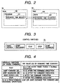
- Fig. 2 is a schematic diagram showing the contents of the ROM 52 and
the RAM;
- Fig. 3 is a diagram showing exemplary presentation control buttons
included in the control switches 70 of Fig. 1;
- Fig. 4 is a table for describing how the scenario time manager 101
sets the value Ct of the scenario time register 501 in response to the executed
presentation control command;
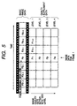
- Fig. 5 is a diagram conceptually showing a data structure of a video
object stored in the mass storage 20 of Fig. 1;
- Fig. 6 is a flowchart showing an exemplary operation of an interrupt
subroutine called from a main program in response to an interrupt caused by
a pressing of one of the presentation control buttons of Fig. 3 after one of the
available programs stored in the mass storage 20 is specified by the user at
the client terminal 3;
- Figs. 7 and 8 are diagrams conceptually showing arrangements of a
first and a second exemplary mass storage 20a and 20b using tape storage
devices;
- Figs. 9 and 10 are diagrams showing a first storing scheme 20c and a
second storing scheme 20d of storing a video object on a disc storage device;
- Fig. 11 is a diagram showing an address table used in the second
storing scheme 20d of Fig. 10;
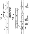
- Fig. 12 is a diagram showing a third storing scheme 20e of storing a
video object on a disc storage device;
- Fig. 13 is a diagram showing a data structure obtained when a
progressive JPEG video object is stored in the third storing scheme 20e as
shown in Fig. 12;
- Fig. 14 is a diagram conceptually showing the H. 263 video format;
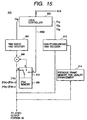
- Fig. 15 is a schematic block diagram showing an exemplary
arrangement of a video decoder 600 which is included in the video & audio
decoder 60 of Fig. 1 and which is adapted to decode a video object of the H. 263
format as shown in Fig. 14;
- Fig. 16 is a diagram showing an exemplary scenario data table of a
multimedia program available in a multimedia-on-demand system according
to a second illustrative embodiment of the invention:
- Fig. 17 is a diagram showing an exemplary active object table created
from the scenario data table of Fig. 16;
- Fig. 18 is a flowchart showing an operation of an interrupt subroutine
called from a main program in response to an interrupt caused by the user at
the client terminal 3 pressing one of the presentation control buttons of Fig. 3
after specifying one of the available multimedia programs stored in the mass
storage 20;
- Fig. 19 is a diagram showing various variable-quality objects used in
an exemplary multimedia program available in the inventive multimedia-on-demand
system;
- Fig. 20 is a diagram showing how the multimedia objects of Fig. 19
are presented in the exemplary multimedia program;
- Fig. 21 is a diagram showing a way of transmitting the multimedia
objects to present the objects as shown in Fig. 20;
- Fig. 22 is a flowchart showing an operation of an interrupt subroutine
called in response to a pressing of one of the presentation control buttons of
Fig. 3 according to the third embodiment of the invention;
- Fig. 23 is a diagram showing an exemplary structure of a scenario
data table according to the third embodiment of the invention; and
- Fig. 24 is a diagram showing an exemplary arrangement of a load
flag storage location.
-
-
Throughout the drawing, the same elements when shown in more
than one figure are designated by the same reference numerals.
DETAILED DESCRIPTION OF THE PREFERRED EMBODIMENTS
-
Fig. 1 is a schematic block diagram showing an arrangement of a
multimedia-on-demand system that can embody the present invention in
various forms. In Fig. 1, double lines indicate bus lines. The multimedia-on-demand
system comprises a server 1 that stores and serves multimedia
programs, at least one client terminal 3 that plays one of the multimedia
programs, and a network 2 for connecting the server 1 and the client
terminals 3.
-
The server 1 comprises a controller 10, a mass storage 20 for storing
the multimedia programs, an object data transmitter 30 for transmitting
object data constituting a multimedia program and a control data
communication interface (IF) 40 for communicating control data with each
client terminal 3. The client terminal 3 comprises an object data receiver 35
for receiving object data transmitted from the server 1; a control data
communication IF 40 for communicating the control data with the server 1; a
controller 50 for controlling the operation of the terminal 3; a video and audio
decoder 60 for decoding video and audio object data into video and audio
output signals; a video output portion 80 for providing a video output
according to the video signal from the decoder 60 and the image data from the
controller 50; a audio output portion 90 for providing an audio output
according to the audio signal from the decoder 60 and the audio data from the
controller 50; and control switches 70 that permit the user to specify a desired
one of the multimedia programs stored in the mass storage 20 and to enter a
play, stop, jump forward, jump backward and head search commands. The
controller 50 includes a read only memory (ROM) 52 and a random access
memory (RAM) 54. The elements 35, 40, 50, 60, 70, 80 and 90 are
interconnected by bus lines 51.
-
Fig. 2 is a schematic diagram showing the contents of the ROM 52
and the RAM. In Fig. 1, the ROM 52 stores programs 100 necessary for the
operation of the controller 50. The RAM 54 stores various data 500 necessary
for the operation of the controller 50. The programs 100 include a scenario
time manager 101, which sets the value (Ct) of a scenario time register 501 in
the RAM 54 in a play operation of a multimedia program such that the
current scenario time or the current position in the multimedia program is
given by T * Ct, where T is a frame period of the video objects.
-
The control switches 70 include presentation control buttons for head
search (HS), jump forward (JF), play, stop, jump backward (JB) operations as
shown in Fig. 3. Fig. 4 shows a table for describing how the scenario time
manager 101 sets the value Ct of the scenario time register 501 in response to
the executed presentation control command. In Fig. 4, if a play command is
issued, the scenario time manger 101 increments the value Ct of the scenario
time register 501 for every frame period T as long as the play command is
active. If a jump forward, a jump backward or a head search is issued, the
scenario time manger 101 sets the scenario time register value Ct to Ct+Cj,
Ct-Cj or 0, respectively. Cj is a predetermined jump distance for use in the JF
and JB operations. In case of a stop command, the scenario time manger 101
does nothing, i.e., the value Ct remains unchanged.
-
Each of the multimedia programs generally comprises video objects,
still picture objects, audio objects and/or text objects.
Embodiment 1
-
For the sake of simplicity, it is assumed in a first illustrative
embodiment of the invention that the multimedia-on-demand system of Fig. 1
is a video-on-demand system, i.e., each of the programs available at each
client comprises a video object.
-
It is also assumed that the data of the video object stored in the mass
storage 20 has a structure as shown in Fig. 5. Data of each frame of the video
object (hereinafter referred to as "each frame data Fh") comprises a basic
image data portion F0f and at least one level (e.g., 4 levels in Fig. 5) of quality
supplement data portions F1f, F2f, F3f and so on. (f = 1, 2, ..., N, where N is
the total number of frames of a video object) The suffix f is the frame number
of the frame. Zero "0" following "F" in a label given to each data portion
indicates that the data portion is the basic image data. A non-zero numeral (1,
2, 3...) following "F" in a label given to each data portion indicates that the
data portion is quality supplement data of the level specified by the non-zero
numeral. The image quality of the f-th frame becomes better to the best by
using not only basic image data F0f but also quality supplement data F1f, F2f,
F3f and so on. In the following description, it is assumed that there are 4
levels of quality supplement data portions F1f, F2f, F3f and F4f for each
frame.
-
In the first illustrative embodiment, the client terminal 3 uses only
the basic image data F01, F02, ..., F0N (hereinafter referred, en bloc, to like
"F0") in a play operation. However, if the terminal 3 detects a stop command
in an arbitrary state of operations or detects one of head search (HS), jump
forward (JF) and jump backward (JB) commands during a stop state, the
terminal 3 performs a image quality enhancing operation on entering a stop
state or just after the operation of the detected command by obtaining the
quality supplement data F1f, F2f, F3f and F4f for the last displayed frame
from the server 1.
-
Since the presented program is a video object in this example, the
scenario time register 501 contains the frame number f, that is, Ct = f.
-
Fig. 6 is a flowchart showing an operation executed by the controller
50 of the client terminal 3 under the control of an interrupt subroutine called
from a main program in response to an interrupt caused by the user at the
client terminal 3 pressing one of the presentation control buttons of Fig. 3
after specifying one of the available programs stored in the mass storage 20.
In Fig. 6, the controller 50 first make s a test in step 122 to see if a play
operation flag (not shown) is logical "1" or indicates that the terminal is in one
of the play modes: i.e., a (normal) play, a jump forward (JF) play, a jump
backward (JB) play, and a head search (HS) play (or a JB play to the
beginning of the program). If so (which means that the terminal 3 is in a play
mode), a test is made in step 124 to see which presentation control command
has been issued.
-
If JB, JF or HS command is detected in step 124, then the controller
50 executes a JB play step 126, a JF play step 128 or a HS play step 130,
respectively, in a well known manner; and returns to the main program that
has invoked this subroutine 120 to resume the play operation that was being
executed when this routine 120 was invoked. If the stop command is detected
in step 124, the controller 50 resets the play operation flag, i.e., sets the flag
logical "0" in step 136; ceases the play mode in step 137; performs an image
quality enhancing operation for the frame identified by the value Ct (= f in
this example) of the scenario time register 501 in step 139; and ends the
operation 120.
-
Specifically, in step 139, the controller 50 transmits an image quality
enhancing instruction and the register 501 value f to the server 1. The
controller 10 of the server 1 responsively reads the quality supplement data
F1f, F2f, F3f and F4f for the frame identified by the value f from the mass
storage 20 and transmits them to the requesting client terminal 3. The
terminal 3 responsively adding the received quality supplement data F1f, F2f,
F3f and F4f to the basic image data F0f into a high quality frame data. By
doing this, the quality of the currently displayed frame becomes better
gradually with the receptions of the quality supplement data F1f, F2f, F3f and
F4f. After step 146, the controller 50 ends the operation 120.
-
If the play operation flag is not logical "1" (which means that the
terminal 3 is in a stop mode), a test is made in step 125 to see which
presentation control command has been issued.
-
If a play command is detected in step 125, the controller 50 sets the
play operation flag logical "1" in step 132; and plays (or reproduces) the
current program (the program the user has specified before the controller 50
has entered the operation 120) from the frame identified by the register 501
value Ct in steps 150, 152 and 154. Specifically, the controller 50 presents the
frame of the register 501 value Ct in step 150 and checks the value Ct to see if
the register value Ct has reached a preset end value in step 152. If not, the
controller 50 increments the value Ct in step 154 and goes back to step 150. If
the register 501 value Ct has reached the preset end value in step 152, then
the controller 50 returns to the main program that has invoked this
subroutine 120.
-
If JB, JF or HS command is detected in step 125, then the controller
50 sets the register 501 value Ct to Ct-Cj, Ct+Cj or 0 in a JB step 140, a JF
step 142 or a HS step 144, respectively, as shown in Fig. 4. After step 140, 142
or 144, the controller 50 performs an image quality enhancing operation for
the frame identified by the scenario time register 501 value before the
execution of step 140, 142 or 144 in step 146. This causes the quality of the
currently displayed frame to get better gradually with the receptions of the
quality supplement data F1f, F2f, F3f and F4f as described above. The
controller 50 ends the operation 120 after step 146.
Some examples of the mass storage 20
-
Figs. 7 and 8 are diagrams conceptually showing arrangements of a
first and a second exemplary mass storage 20a and 20b using tape storage
devices. The storage 20a comprises five tape storage devices 211 through 215.
The tape device 211 stores the basic image data F0. The four tape devices 212
through 215 store the four level quality supplement data F1 through F4,
respectively. The basic image data F0f and the corresponding quality
supplement data F1f, F2f, F3f and F4f for each frame are recorded on the
same tape positions of the five tapes. The five tape storage devices are so
arranged that the five reels are independently rotated only in case of image
quality enhancing operation and are synchronously rotated otherwise. In an
image quality enhancing operation, the tape storage devices 212 through 215
for the quality supplement data F1 through F4 are sequentially read one by
one.
-
The storage 20b comprises two tape storage devices 217 and 218. The
tape device 217 stores the basic image data F0. The tape device 218 stores the
four level quality supplement data F1 through F4. The quality supplement
data F1f, F2f, F3f and F4f for each frame are recorded on the tape position of
the tape 218 which corresponds to the position of the tape 217 on which the
basic image data F0f for the frame is recorded when the tapes 217 and 218 are
rotated synchronously. The two tape devices 217 and 218 are so arranged that
the two reels are independently rotated only in case of image quality
enhancing operation and are synchronously rotated otherwise. In an image
quality enhancing operation, the tape storage device 218 portion for the
quality supplement data F1f through F4f are sequentially read.
-
Figs. 9 and 10 show a first storing scheme 20c and a second storing
scheme 20d of storing a video object on the mass storage 20. The mass storage
20 may be any suitable disc storage device such as a hard disc, various optical
discs, etc. The basic image data F0 and the quality supplement data (QSD) F1,
F2,... are stored in two different areas: a F0 area and a QSD area on the third
mass storage media.
-
In the first storing scheme 20c of Fig. 9, it is assumed that the
quantity of the quality supplement data (QSD) F1f, F2f, F3f and F4f for each
frame is M times the data quantity of the basic image data F0f for the frame,
where M is a positive constant. Then, if the first data of the basic image data
F0f is (N+1)-th byte in the F0 area, then in order to obtain the quality
supplement data F1f, F2f, F3f and F4f, the controller 40 has only to read the
data of D * M bytes from the (N * M+1)-th byte in the QSD area. D is the data
size of the basic image data for each frame.
-
In the second storing scheme 20d of Fig. 10, the basic image data F0f
and the total quality supplement data F1f + F2f + F3f + F4f may have
arbitrary sizes. The start address of the total quality supplement data for an
f-th frame in the QSD area is assumed to be Af. In order to know the quality
supplement data address Af from the frame number f, the controller 10 uses
an address table of Fig. 11. The address table of Fig. 11 comprises a frame
number (f) field and a field of QSD address (Af) for the frame number (f).
-
Fig. 12 shows a third storing scheme 20e of storing a video object on
the mass storage 20. The mass storage 20 preferably comprises a suitable disc
storage device such as a hard disc, various optical discs, etc. In this storing
scheme 20e, the basic image data F0f and the quality supplement data QSDf
(= F1f + F2f +...) are stored in a same area with the latter just following the
former in a manner like F0f-1, QSDf-1, F0f, QSDf, F0f+1, QSDf+1 and so on. In this
case, in normal play step 150 of Fig. 6, the controller 10 reads only the basic
image data skipping the quality supplement data as shown by arrows above
the strip area representative of the stored video data in Fig. 12. In the image
quality enhancing operation in step 146, the controller 10 reads the quality
supplement data QSDf for the frame identified by the register 501 value as
shown by an arrow below the strip area representative of the stored video data
in Fig. 12.
Progressive JPEG Format
-
The invention is applicable to video data of formats in which some of
the frames are described by using differential data between frames: e.g., the
progressive JPEG format, the H. 263 format, MPEG-1 format and the MPEG-2
format. Fig. 13 is a diagram showing a data structure obtained when a
progressive JPEG video object is stored in the third storing scheme 20e as
shown in Fig. 12. In Fig. 13, the basic image data F0f for each frame comprises
a header F0Hf and a basic image data portion F0Df. The quality supplement
data QSDf comprises a first level differential data F1t, a second level
differential data F2f, ..., and an L-th level differential data FLf.
-
In case of the progressive JPEG format, in normal play step 150 of
Fig. 6, the controller 10 reads only the header F0Hf and the basic image data
F0Df skipping the quality supplement data QSDf (=F1f, F2f,..., and FLf) for
each frame f. In the image quality enhancing operation in step 146, the
controller 10 reads the quality supplement data QSDf for the frame identified
by the register 501 value.
-
It is noted that the controller 50 passes the frame data to be
displayed to the video & audio decoder 60 of Fig. 1 in playing operations of
steps 126, 128, 130 and 150. In case of the progressive JPEG format, the video
& audio decoder 60 includes a JPEG decoder.
H. 263 Format
-
Fig. 14 is a diagram conceptually showing the H. 263 video format. In
Fig. 14, an H. 263 video data comprises basic image data 210 for use in a play
operation and quality supplement data 220 for use in a quality enhancing
operation. If the frame data for the basic image data are expressed as F00, F01,
F02, ..., F0g, ..., and F03N+2 (g is a frame number), then the frame data can be
expressed as {F03f, F03f+1, F03f+2: f = 0, 1,..., N}. In this case, the basic image
frames identified by F03f are intra-coded frames that can be decoded alone
without the need of data of any other frame. On the other hand, the basic
image frames identified by F0f3+1 and F0f3+2 are first and second differences, in
the time direction, from the basic image data F03f which needs frame F03f data
for decoding. The first and second differences are written as TIME
DIRECTION DIF 1 and 2, respectively in Fig. 14. The quality supplement
data for the frame 3f comprises first, second and third differences, in the
quality direction, from the basic image data F03f, which differences are
referred to as " QUALITY DIFs 1, 2 and 3" and labeled "F13f", "F23f" and "F33f",
respectively. In a similarly manner, the quality supplement data for the frame
3f+1 comprises QUALITY DIFs 1, 2 and 3 from the basic image data F03f+1
which differences are labeled "F13f+1", "F23f+1" and "F33f+1", respectively. Also,
the quality supplement data for the frame 3f+2 comprises QUALITY DIFs 1, 2
and 3 from the basic image data F03f+2 which differences are labeled "F13f+2",
"F23f+2" and "F33f+2", respectively.
-
Fig. 15 is a schematic block diagram showing an exemplary
arrangement of a video decoder 600 which is included in the video & audio
decoder 60 of Fig. 1 and which is adapted to decode a video object of the H. 263
format as shown in Fig. 14. In Fig. 15, the video decoder 600 comprises a local
controller 602 for controlling the operation of the decoder 600; a time-based H.
263 decoder 604; an adder 606; a frame memory 608 for storing a I-coded
image data F03f: a memory interface 610 for the memory 608; a quality-enhancing
H. 263 decoder 612 for decoding quality supplement data F1g, F2g
and F3g to provide a quality-enhanced frame data F0g+F1g+F2g+F3g; and a
previous frame memory for quality enhancement.
-
The received video data is passed to the video & audio decider 60 and
to the video decoder 600 or the local controller 602 through the bus lines 51. If
the received video data is basic image data F0g, then the local controller 602
passes the data F0g to the time-based H. 263 decider 604. If the received video
data is quality supplement data F1g, F2g or F3g, then the local controller 602
passes the data F1g, F2g or F3g to the quality-enhancing H. 263 decider 612.
-
The local controller 602 supplies a control signal 602a to a memory
interface 610 control input 610c. The control signal 602a controls the memory
interface 610 such that the data on the interface 610 data input terminal 610a
is stored in the memory 608 if the received video data is I-coded image data,
i.e., g = 3f. Thus, if the received video data is F03f, the decoded video data [F03f]
is stored in the frame memory 608, where [A] represents a decoded version of
data A.
-
The control signal 602a also controls the memory interface 610 such
that the data stored in the frame memory 608, i.e., the decoded video data
[F03f] is read out to a memory interface 610 data output terminal 610b if the
received video data is not I-coded image data, i.e., g ≠ 3f. Thus, if the
received video data is F03f+1 or F03f+2, the decoded video data [F03f+1] or [F03f+2]
is added by the adder 606 to the decoded video data [F03f] read from the
memory 608 to yield the added decoded video data [F03f]+ [F03f+1] or [F03f]+
[F03f+2], respectively, which is supplied to the video output portion 80 and the
previous frame memory 614.
-
To the previous frame memory 614, there are also supplied the
decoded video data from the quality-enhancing H. 263 decoder 612. The H.
263 decoder 612 decodes the quality supplement data F1g, F2g or F3g from
the local controller 602, and adds the decoded data [F1g], [F2g] or [F3g] to the
data from the previous frame memory 614 to provide the quality enhanced
frame data to the video output portion 80.
-
It is noted that since the video decoder 600 has respective previous
frame memories 608 and 614 and respective H. 263 decoders 604 and 612 for a
decoding in the time axis direction and a decoding in the quality axis direction,
it is possible to store data decoded in the time axis direction in both of the
previous frame memory 608 and 614 and to store data decoded in the quality
axis direction only in the memory 614 for the quality axis direction. This
reason, even if quality supplement data for a frame data F0g has been decoded,
it is possible to resume the play of video data from the frame data F0g.
-
Though the above-described video decoder 600 has used two H. 263
decoders, an equivalent video decoder may be implemented by using a single
decoder.
-
A video decoder that decodes a video object of a format using a
correlation between frames not only in the time axis direction but also in the
quality axis direction has been described in conjunction with the H. 263 video
format. However, such a video decoder can be realized for other such video
format as MPEG format by replacing the H. 263 decoder(s) with a
corresponding video decoder such as an MPEG decoder.
-
Though the above-described embodiments has dealt with a single
media program, i.e., a video object, the following embodiment deals with a
multimedia program.
Embodiment II
-
A multimedia-on-demand system according to a second illustrative
embodiment of the invention has a feature of enhancing the picture quality of
the first frame to be displayed after the execution of a stop command or the
execution of a JF, JB or HS command issued during a stop state by
transmitting quality supplement data from the server 1.
-
Fig. 16 is a diagram showing an exemplary scenario data table of a
multimedia program available in a multimedia-on-demand system according
to a second illustrative embodiment of the invention. In Fig. 16, the scenario
data table contains a record for each of the multimedia objects used in the
multimedia program for which the scenario data table is intended. Each
record of the scenario data table comprises the fields of the object ID, the kind
of the object, the display position on a screen, the display size, the
presentation start time and the presentation end time. For the sake of better
understanding, in the presentation start and end time fields, there is included
corresponding value of the scenario time counter 501, Ct. In this specific
example, the frame rate of the video objects is assumed to be 30 frames per
second.
-
In order to simplify the operation, it is preferable to create an active
object table as shown in Fig. 17 from the scenario data table. In Fig. 17, all of
the Ct values found in the presentation start and end time fields of the
scenario data table are listed in the ascending order in the first column or
fields of the event list table. For each of the listed Ct values, there are listed,
in the second field, the object IDs of multimedia objects the presentation of
which is started or ongoing at the Ct value. However, each second field does
not include the object the presentation of which ends at the Ct values.
-
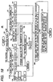
Fig. 18 is a flowchart showing an operation executed by the controller
50 of the client terminal 3 under the control of an interrupt subroutine called
from a main program in response to an interrupt caused by the user at the
client terminal 3 pressing one of the presentation control buttons of Fig. 3
after specifying one of the available multimedia programs stored in the mass
storage 20. Since the operation 220 of Fig. 18 is very similarly to that of Fig. 6,
only the difference between them will be described in the following.
-
If JB, JF or HS command is detected in step 124, then instead of
executing a JB play step 126, a JF play step 128 or a HS play step 130, the
controller 50 sets the register 501 value Ct to Ct-Cj, Ct+Cj or 0 in a JB step
240, a JF step 242 or a HS step 244, respectively; and returns to the main
program to resumes the normal play operation of the current program from
the register 501.
-
In step 250 of the normal play operation comprising steps 250, 152 and
154, the controller 50 presents relevant object(s) referring to the active object
table of Fig. 17. Specifically, if the current value Ct is found in any Ct field of
the table, the controller 50 continues the presentation of the object(s) which is
(or are) listed in both the current record whose Ct field contains the current Ct
value and the just above records in the table; ceases the presentation of the
object(s) which is (or are) found in the just above record but not found in the
current record, and starts the presentation of the object(s) which first appears
(or appear) in the current record. If the current value Ct is not found in any Ct
field of the active object table, the controller 50 has only to repeat the same
operation as executed for the last Ct value.
-
in a manner well known in the art. In this case, if a video frame is to
be displayed, the controller 50 only uses basic data for the frame.
-
After step 137, 140, 142 or 144, the controller 50 makes a test in step
238 to see if a video object exists in the record whose Ct value filed contains a
largest value not exceeding the value of the scenario time register 501, Ct. If
so, the controller 50 performs the image enhancing operation for the frame
identified by the current register 501 value Ct minus the register 501 value of
the presentation start time SCt of the video object in step 139. This is because
the current register value Ct equals the sum of the presentation start time Ct
value SCt and the frame number of the video object.
-
After step 139, the controller 50 ends the operation 220. If the test
result is NO in step 238, then the controller 50 ends the operation 220.
-
As described above, the image enhancing operation of step 139
enhances the picture quality of the frame to be displayed after the execution of
a stop command or the execution of a JF, JB or HS command issued during a
stop state.
-
It should be noted that the image enhancing operation may be
performed for a plurality of frames beginning the frame identified by the value
of Ct-SCt.
Embodiment III
-
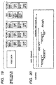
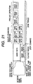
According to a third illustrative embodiment of the invention, a
multimedia-on-demand system adds detailed information to (or enhances the
quality of) each of variable-quality objects during a stop period in a manner as
illustrated by a part labeled "QUALITY ENHANCING OPERATION" in Fig.
21. A variable-quality object is a multimedia object that comprises a plurality
of detail levels of data and that permits an enhancement of the presentation
quality by adding a higher detail level of data. The above-mentioned
progressive JPEG video is one of such variable-quality objects. Fig. 19 is a
diagram showing examples of variable-quality objects. In Fig. 19, still pictures
A, B, C and D are variable in the display quality according to the difference
data levels used for presentation. Also, the text object of Fig. 19 is said to be a
variable -quality object since the text object comprises a plurality of detail
levels of data.
-
Also, the client terminal of the multimedia-on-demand system tries to
collect as much object data as possible in advance during a stop period so that
a random access operation such as a JF operation can be promptly executed.
This collection operation is shown by a part labeled "PRELOAD
OPERATION" again in Fig. 21.
-
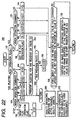
Fig. 22 is a flowchart showing an operation of an interrupt subroutine
230 called in response to a pressing of one of the presentation control buttons
of Fig. 3 according to the third embodiment of the invention. The interrupt
subroutine 230 is identical to that of Fig. 18 except that after step 137, the
controller 50 executes steps 260 and 270 instead of proceeding to step 238.
-
In step 260, the controller 50 performs an image quality enhancing
operation for at least one frame beginning the frame identified by the value of
Ct - SCt for each of the active variable-quality objects. For this purpose, it is
preferable to add an field 265 for containing a variable-quality flag indicative
of whether the objet is variable in presentation quality or a loading priority
code indicative of the priority order of the object in a load operation as shown
in Fig. 23. If there are a plurality of active objects with an identical priority
code, the controller 50 preferably processes the objects in order of
presentation.
-
Also, it is preferable to keep a load flag for each object as shown in Fig.
24. The load flag for an object indicates whether the basic data of the object
has been loaded or not. The load flags are all reset in an initial operation.
-
In step 270, the controller 50 preferably tries to load basic data of as
many object to be subsequently presented as possible in advance. In order to
distinguish the loaded object from not-loaded ones, the controller 50 sets the
load flag each time the load operation of the basic data of an object has been
completed. This enables a quick response in a random access operation such
as a fast ford operation.
-
Many widely different embodiments of the present invention may be
constructed without departing from the spirit and scope of the present
invention. It should be understood that the present invention is not limited to
the specific embodiments described in the specification, except as defined in
the appended claims.