EP0967293A2 - Functionally graded alloy, use thereof and method for producing the same - Google Patents
Functionally graded alloy, use thereof and method for producing the same Download PDFInfo
- Publication number
- EP0967293A2 EP0967293A2 EP99305087A EP99305087A EP0967293A2 EP 0967293 A2 EP0967293 A2 EP 0967293A2 EP 99305087 A EP99305087 A EP 99305087A EP 99305087 A EP99305087 A EP 99305087A EP 0967293 A2 EP0967293 A2 EP 0967293A2
- Authority
- EP
- European Patent Office
- Prior art keywords
- temperature
- catheter
- tip end
- alloy
- copper
- Prior art date
- Legal status (The legal status is an assumption and is not a legal conclusion. Google has not performed a legal analysis and makes no representation as to the accuracy of the status listed.)
- Granted
Links
- 229910045601 alloy Inorganic materials 0.000 title claims abstract description 170
- 239000000956 alloy Substances 0.000 title claims abstract description 170
- 238000004519 manufacturing process Methods 0.000 title claims description 6
- 239000010949 copper Substances 0.000 claims abstract description 89
- 230000032683 aging Effects 0.000 claims abstract description 81
- RYGMFSIKBFXOCR-UHFFFAOYSA-N Copper Chemical compound [Cu] RYGMFSIKBFXOCR-UHFFFAOYSA-N 0.000 claims abstract description 70
- 229910052802 copper Inorganic materials 0.000 claims abstract description 70
- 238000011282 treatment Methods 0.000 claims abstract description 57
- 239000013078 crystal Substances 0.000 claims abstract description 36
- 239000000203 mixture Substances 0.000 claims abstract description 18
- 238000001816 cooling Methods 0.000 claims abstract description 15
- 239000012535 impurity Substances 0.000 claims abstract description 13
- 239000002184 metal Substances 0.000 claims description 30
- 229910052751 metal Inorganic materials 0.000 claims description 30
- 230000003247 decreasing effect Effects 0.000 claims description 25
- 238000010438 heat treatment Methods 0.000 claims description 25
- 238000011084 recovery Methods 0.000 claims description 22
- 230000003014 reinforcing effect Effects 0.000 claims description 16
- 238000009826 distribution Methods 0.000 claims description 14
- 238000005452 bending Methods 0.000 claims description 10
- 238000005482 strain hardening Methods 0.000 claims description 9
- 230000035882 stress Effects 0.000 claims description 8
- 229910052737 gold Inorganic materials 0.000 claims description 7
- 229910052750 molybdenum Inorganic materials 0.000 claims description 7
- 229910052758 niobium Inorganic materials 0.000 claims description 7
- 229910052718 tin Inorganic materials 0.000 claims description 7
- 229910052719 titanium Inorganic materials 0.000 claims description 7
- 229910052720 vanadium Inorganic materials 0.000 claims description 7
- 150000002739 metals Chemical class 0.000 claims description 6
- 229910052726 zirconium Inorganic materials 0.000 claims description 6
- 230000007423 decrease Effects 0.000 claims description 5
- 229910052742 iron Inorganic materials 0.000 claims description 5
- 229910052759 nickel Inorganic materials 0.000 claims description 5
- 229920005989 resin Polymers 0.000 claims description 5
- 239000011347 resin Substances 0.000 claims description 5
- 229910052721 tungsten Inorganic materials 0.000 claims description 5
- ATJFFYVFTNAWJD-UHFFFAOYSA-N Tin Chemical compound [Sn] ATJFFYVFTNAWJD-UHFFFAOYSA-N 0.000 claims description 3
- 229910052796 boron Inorganic materials 0.000 claims description 3
- 229910052804 chromium Inorganic materials 0.000 claims description 3
- 229910052749 magnesium Inorganic materials 0.000 claims description 3
- 238000000034 method Methods 0.000 claims description 3
- 229910052763 palladium Inorganic materials 0.000 claims description 3
- 229910052698 phosphorus Inorganic materials 0.000 claims description 3
- 229910052697 platinum Inorganic materials 0.000 claims description 3
- 229910052710 silicon Inorganic materials 0.000 claims description 3
- 229910052709 silver Inorganic materials 0.000 claims description 3
- 229910052725 zinc Inorganic materials 0.000 claims description 3
- 239000010410 layer Substances 0.000 description 26
- 229910018131 Al-Mn Inorganic materials 0.000 description 21
- 229910018461 Al—Mn Inorganic materials 0.000 description 21
- 210000004204 blood vessel Anatomy 0.000 description 18
- 239000000463 material Substances 0.000 description 14
- 229910000756 V alloy Inorganic materials 0.000 description 13
- TZCXTZWJZNENPQ-UHFFFAOYSA-L barium sulfate Chemical compound [Ba+2].[O-]S([O-])(=O)=O TZCXTZWJZNENPQ-UHFFFAOYSA-L 0.000 description 10
- 238000003780 insertion Methods 0.000 description 9
- 230000037431 insertion Effects 0.000 description 9
- 239000004952 Polyamide Substances 0.000 description 7
- 229920001971 elastomer Polymers 0.000 description 7
- 239000000806 elastomer Substances 0.000 description 7
- KHYBPSFKEHXSLX-UHFFFAOYSA-N iminotitanium Chemical compound [Ti]=N KHYBPSFKEHXSLX-UHFFFAOYSA-N 0.000 description 7
- 238000002156 mixing Methods 0.000 description 7
- 229910001000 nickel titanium Inorganic materials 0.000 description 7
- 229920002647 polyamide Polymers 0.000 description 7
- 230000001050 lubricating effect Effects 0.000 description 6
- 239000002872 contrast media Substances 0.000 description 5
- 239000010931 gold Substances 0.000 description 5
- 230000003287 optical effect Effects 0.000 description 5
- 229920000036 polyvinylpyrrolidone Polymers 0.000 description 5
- 235000013855 polyvinylpyrrolidone Nutrition 0.000 description 5
- 239000001267 polyvinylpyrrolidone Substances 0.000 description 5
- IJGRMHOSHXDMSA-UHFFFAOYSA-N Atomic nitrogen Chemical compound N#N IJGRMHOSHXDMSA-UHFFFAOYSA-N 0.000 description 4
- 239000011247 coating layer Substances 0.000 description 4
- PCHJSUWPFVWCPO-UHFFFAOYSA-N gold Chemical compound [Au] PCHJSUWPFVWCPO-UHFFFAOYSA-N 0.000 description 4
- 238000007654 immersion Methods 0.000 description 4
- 238000005461 lubrication Methods 0.000 description 4
- 229910001120 nichrome Inorganic materials 0.000 description 4
- 239000000243 solution Substances 0.000 description 4
- -1 Ni-Ti alloys Chemical class 0.000 description 3
- 230000015572 biosynthetic process Effects 0.000 description 3
- 230000000052 comparative effect Effects 0.000 description 3
- 238000005520 cutting process Methods 0.000 description 3
- 230000008021 deposition Effects 0.000 description 3
- 239000005457 ice water Substances 0.000 description 3
- 229910000734 martensite Inorganic materials 0.000 description 3
- 239000011159 matrix material Substances 0.000 description 3
- 238000005259 measurement Methods 0.000 description 3
- 239000000843 powder Substances 0.000 description 3
- 239000000126 substance Substances 0.000 description 3
- 238000009864 tensile test Methods 0.000 description 3
- 230000009466 transformation Effects 0.000 description 3
- 238000004804 winding Methods 0.000 description 3
- KKJUPNGICOCCDW-UHFFFAOYSA-N 7-N,N-Dimethylamino-1,2,3,4,5-pentathiocyclooctane Chemical compound CN(C)C1CSSSSSC1 KKJUPNGICOCCDW-UHFFFAOYSA-N 0.000 description 2
- 229910020639 Co-Al Inorganic materials 0.000 description 2
- 229910002515 CoAl Inorganic materials 0.000 description 2
- 229910020675 Co—Al Inorganic materials 0.000 description 2
- JHWNWJKBPDFINM-UHFFFAOYSA-N Laurolactam Chemical compound O=C1CCCCCCCCCCCN1 JHWNWJKBPDFINM-UHFFFAOYSA-N 0.000 description 2
- 229910018651 Mn—Ni Inorganic materials 0.000 description 2
- 229910000943 NiAl Inorganic materials 0.000 description 2
- 229920000299 Nylon 12 Polymers 0.000 description 2
- NPXOKRUENSOPAO-UHFFFAOYSA-N Raney nickel Chemical compound [Al].[Ni] NPXOKRUENSOPAO-UHFFFAOYSA-N 0.000 description 2
- 239000003245 coal Substances 0.000 description 2
- 239000002131 composite material Substances 0.000 description 2
- 230000007797 corrosion Effects 0.000 description 2
- 238000005260 corrosion Methods 0.000 description 2
- 238000002003 electron diffraction Methods 0.000 description 2
- 238000005530 etching Methods 0.000 description 2
- 229920002313 fluoropolymer Polymers 0.000 description 2
- 229910000765 intermetallic Inorganic materials 0.000 description 2
- 238000010030 laminating Methods 0.000 description 2
- 239000007788 liquid Substances 0.000 description 2
- 239000011812 mixed powder Substances 0.000 description 2
- 229910052757 nitrogen Inorganic materials 0.000 description 2
- 238000007747 plating Methods 0.000 description 2
- 238000010791 quenching Methods 0.000 description 2
- 230000000171 quenching effect Effects 0.000 description 2
- 238000005096 rolling process Methods 0.000 description 2
- 238000005245 sintering Methods 0.000 description 2
- 239000010935 stainless steel Substances 0.000 description 2
- 229910001220 stainless steel Inorganic materials 0.000 description 2
- 238000005728 strengthening Methods 0.000 description 2
- XLYOFNOQVPJJNP-UHFFFAOYSA-N water Substances O XLYOFNOQVPJJNP-UHFFFAOYSA-N 0.000 description 2
- 238000003466 welding Methods 0.000 description 2
- 229910000975 Carbon steel Inorganic materials 0.000 description 1
- IEPRKVQEAMIZSS-UHFFFAOYSA-N Di-Et ester-Fumaric acid Natural products CCOC(=O)C=CC(=O)OCC IEPRKVQEAMIZSS-UHFFFAOYSA-N 0.000 description 1
- IEPRKVQEAMIZSS-WAYWQWQTSA-N Diethyl maleate Chemical compound CCOC(=O)\C=C/C(=O)OCC IEPRKVQEAMIZSS-WAYWQWQTSA-N 0.000 description 1
- 229910000914 Mn alloy Inorganic materials 0.000 description 1
- 239000004698 Polyethylene Substances 0.000 description 1
- 239000004743 Polypropylene Substances 0.000 description 1
- 239000004793 Polystyrene Substances 0.000 description 1
- 239000004433 Thermoplastic polyurethane Substances 0.000 description 1
- 238000002441 X-ray diffraction Methods 0.000 description 1
- 230000003679 aging effect Effects 0.000 description 1
- 238000000137 annealing Methods 0.000 description 1
- 239000010962 carbon steel Substances 0.000 description 1
- 239000011248 coating agent Substances 0.000 description 1
- 238000000576 coating method Methods 0.000 description 1
- 238000005097 cold rolling Methods 0.000 description 1
- 229940039231 contrast media Drugs 0.000 description 1
- 239000002826 coolant Substances 0.000 description 1
- 229920001577 copolymer Polymers 0.000 description 1
- 238000013461 design Methods 0.000 description 1
- 230000002542 deteriorative effect Effects 0.000 description 1
- 238000009792 diffusion process Methods 0.000 description 1
- DQJJMWZRDSGUJP-UHFFFAOYSA-N ethenoxyethene;furan-2,5-dione Chemical class C=COC=C.O=C1OC(=O)C=C1 DQJJMWZRDSGUJP-UHFFFAOYSA-N 0.000 description 1
- 230000006870 function Effects 0.000 description 1
- 238000005098 hot rolling Methods 0.000 description 1
- 238000002347 injection Methods 0.000 description 1
- 239000007924 injection Substances 0.000 description 1
- 239000000155 melt Substances 0.000 description 1
- 239000007769 metal material Substances 0.000 description 1
- 229920000728 polyester Polymers 0.000 description 1
- 229920000573 polyethylene Polymers 0.000 description 1
- 229920001155 polypropylene Polymers 0.000 description 1
- 229920002223 polystyrene Polymers 0.000 description 1
- 229920002635 polyurethane Polymers 0.000 description 1
- 239000004814 polyurethane Substances 0.000 description 1
- 229920005749 polyurethane resin Polymers 0.000 description 1
- 239000004800 polyvinyl chloride Substances 0.000 description 1
- 229920000915 polyvinyl chloride Polymers 0.000 description 1
- 238000003825 pressing Methods 0.000 description 1
- 238000011160 research Methods 0.000 description 1
- 238000005204 segregation Methods 0.000 description 1
- 229920002379 silicone rubber Polymers 0.000 description 1
- 238000004381 surface treatment Methods 0.000 description 1
- 229920003002 synthetic resin Polymers 0.000 description 1
- 239000000057 synthetic resin Substances 0.000 description 1
- 229920002803 thermoplastic polyurethane Polymers 0.000 description 1
- 150000003568 thioethers Chemical class 0.000 description 1
- 238000007740 vapor deposition Methods 0.000 description 1
Images


Classifications
-
- A—HUMAN NECESSITIES
- A61—MEDICAL OR VETERINARY SCIENCE; HYGIENE
- A61L—METHODS OR APPARATUS FOR STERILISING MATERIALS OR OBJECTS IN GENERAL; DISINFECTION, STERILISATION OR DEODORISATION OF AIR; CHEMICAL ASPECTS OF BANDAGES, DRESSINGS, ABSORBENT PADS OR SURGICAL ARTICLES; MATERIALS FOR BANDAGES, DRESSINGS, ABSORBENT PADS OR SURGICAL ARTICLES
- A61L29/00—Materials for catheters, medical tubing, cannulae, or endoscopes or for coating catheters
- A61L29/02—Inorganic materials
-
- B—PERFORMING OPERATIONS; TRANSPORTING
- B32—LAYERED PRODUCTS
- B32B—LAYERED PRODUCTS, i.e. PRODUCTS BUILT-UP OF STRATA OF FLAT OR NON-FLAT, e.g. CELLULAR OR HONEYCOMB, FORM
- B32B15/00—Layered products comprising a layer of metal
- B32B15/04—Layered products comprising a layer of metal comprising metal as the main or only constituent of a layer, which is next to another layer of the same or of a different material
- B32B15/08—Layered products comprising a layer of metal comprising metal as the main or only constituent of a layer, which is next to another layer of the same or of a different material of synthetic resin
-
- A—HUMAN NECESSITIES
- A61—MEDICAL OR VETERINARY SCIENCE; HYGIENE
- A61L—METHODS OR APPARATUS FOR STERILISING MATERIALS OR OBJECTS IN GENERAL; DISINFECTION, STERILISATION OR DEODORISATION OF AIR; CHEMICAL ASPECTS OF BANDAGES, DRESSINGS, ABSORBENT PADS OR SURGICAL ARTICLES; MATERIALS FOR BANDAGES, DRESSINGS, ABSORBENT PADS OR SURGICAL ARTICLES
- A61L31/00—Materials for other surgical articles, e.g. stents, stent-grafts, shunts, surgical drapes, guide wires, materials for adhesion prevention, occluding devices, surgical gloves, tissue fixation devices
- A61L31/02—Inorganic materials
- A61L31/022—Metals or alloys
-
- B—PERFORMING OPERATIONS; TRANSPORTING
- B32—LAYERED PRODUCTS
- B32B—LAYERED PRODUCTS, i.e. PRODUCTS BUILT-UP OF STRATA OF FLAT OR NON-FLAT, e.g. CELLULAR OR HONEYCOMB, FORM
- B32B1/00—Layered products having a general shape other than plane
- B32B1/08—Tubular products
-
- B—PERFORMING OPERATIONS; TRANSPORTING
- B32—LAYERED PRODUCTS
- B32B—LAYERED PRODUCTS, i.e. PRODUCTS BUILT-UP OF STRATA OF FLAT OR NON-FLAT, e.g. CELLULAR OR HONEYCOMB, FORM
- B32B15/00—Layered products comprising a layer of metal
- B32B15/02—Layer formed of wires, e.g. mesh
-
- B—PERFORMING OPERATIONS; TRANSPORTING
- B32—LAYERED PRODUCTS
- B32B—LAYERED PRODUCTS, i.e. PRODUCTS BUILT-UP OF STRATA OF FLAT OR NON-FLAT, e.g. CELLULAR OR HONEYCOMB, FORM
- B32B15/00—Layered products comprising a layer of metal
- B32B15/20—Layered products comprising a layer of metal comprising aluminium or copper
-
- C—CHEMISTRY; METALLURGY
- C22—METALLURGY; FERROUS OR NON-FERROUS ALLOYS; TREATMENT OF ALLOYS OR NON-FERROUS METALS
- C22C—ALLOYS
- C22C9/00—Alloys based on copper
- C22C9/01—Alloys based on copper with aluminium as the next major constituent
-
- C—CHEMISTRY; METALLURGY
- C22—METALLURGY; FERROUS OR NON-FERROUS ALLOYS; TREATMENT OF ALLOYS OR NON-FERROUS METALS
- C22C—ALLOYS
- C22C9/00—Alloys based on copper
- C22C9/05—Alloys based on copper with manganese as the next major constituent
-
- C—CHEMISTRY; METALLURGY
- C22—METALLURGY; FERROUS OR NON-FERROUS ALLOYS; TREATMENT OF ALLOYS OR NON-FERROUS METALS
- C22F—CHANGING THE PHYSICAL STRUCTURE OF NON-FERROUS METALS AND NON-FERROUS ALLOYS
- C22F1/00—Changing the physical structure of non-ferrous metals or alloys by heat treatment or by hot or cold working
- C22F1/08—Changing the physical structure of non-ferrous metals or alloys by heat treatment or by hot or cold working of copper or alloys based thereon
-
- B—PERFORMING OPERATIONS; TRANSPORTING
- B32—LAYERED PRODUCTS
- B32B—LAYERED PRODUCTS, i.e. PRODUCTS BUILT-UP OF STRATA OF FLAT OR NON-FLAT, e.g. CELLULAR OR HONEYCOMB, FORM
- B32B2311/00—Metals, their alloys or their compounds
- B32B2311/12—Copper
-
- B—PERFORMING OPERATIONS; TRANSPORTING
- B32—LAYERED PRODUCTS
- B32B—LAYERED PRODUCTS, i.e. PRODUCTS BUILT-UP OF STRATA OF FLAT OR NON-FLAT, e.g. CELLULAR OR HONEYCOMB, FORM
- B32B2535/00—Medical equipment, e.g. bandage, prostheses, catheter
-
- B—PERFORMING OPERATIONS; TRANSPORTING
- B32—LAYERED PRODUCTS
- B32B—LAYERED PRODUCTS, i.e. PRODUCTS BUILT-UP OF STRATA OF FLAT OR NON-FLAT, e.g. CELLULAR OR HONEYCOMB, FORM
- B32B2597/00—Tubular articles, e.g. hoses, pipes
-
- Y—GENERAL TAGGING OF NEW TECHNOLOGICAL DEVELOPMENTS; GENERAL TAGGING OF CROSS-SECTIONAL TECHNOLOGIES SPANNING OVER SEVERAL SECTIONS OF THE IPC; TECHNICAL SUBJECTS COVERED BY FORMER USPC CROSS-REFERENCE ART COLLECTIONS [XRACs] AND DIGESTS
- Y10—TECHNICAL SUBJECTS COVERED BY FORMER USPC
- Y10T—TECHNICAL SUBJECTS COVERED BY FORMER US CLASSIFICATION
- Y10T428/00—Stock material or miscellaneous articles
- Y10T428/12—All metal or with adjacent metals
- Y10T428/12014—All metal or with adjacent metals having metal particles
- Y10T428/12021—All metal or with adjacent metals having metal particles having composition or density gradient or differential porosity
-
- Y—GENERAL TAGGING OF NEW TECHNOLOGICAL DEVELOPMENTS; GENERAL TAGGING OF CROSS-SECTIONAL TECHNOLOGIES SPANNING OVER SEVERAL SECTIONS OF THE IPC; TECHNICAL SUBJECTS COVERED BY FORMER USPC CROSS-REFERENCE ART COLLECTIONS [XRACs] AND DIGESTS
- Y10—TECHNICAL SUBJECTS COVERED BY FORMER USPC
- Y10T—TECHNICAL SUBJECTS COVERED BY FORMER US CLASSIFICATION
- Y10T428/00—Stock material or miscellaneous articles
- Y10T428/12—All metal or with adjacent metals
- Y10T428/12458—All metal or with adjacent metals having composition, density, or hardness gradient
Abstract
Description
- The present invention relates to a copper-based, functionally graded alloy having uniform composition and diameter and continuously or stepwise changing properties such as hardness, modulus elongation, etc. and a method for producing such an alloy, and use of such an alloy in guide wires, catheters, etc.
- Functionally graded alloys are materials having continuously or stepwise changing properties such as hardness, elasticity, thermal conductivity, electric conductivity, etc. without gradient in size given by mechanical working such as cutting, etc. or chemical treatments such as etching, etc. Functionally graded materials developed so far are mostly such two-component composites as SiC/C, ZrO/W, TiC/Ni, ZrO/Ni, etc., which have gradually changing mixing ratios.
- Conventional functionally graded materials having gradually changing mixing ratios have been produced by mixing different material powders at gradually changing mixing ratios to prepare a plurality of mixed powder sheets having gradually changing mixing ratios, laminating the mixed powder sheets along the gradually changing mixing ratios, compacting and sintering them. For example, Japanese Patent Laid-Open No. 5-278158 discloses a functionally graded, binary metal material produced by laminating and sintering W powder and Mo powder at a gradually changing mixing ratio.
- However, the functionally graded materials produced by such a method cannot be rolled or drawn, and they can be formed to desired shapes only by cutting. Thus, they are not only very expensive but also cannot be formed into complicated shapes. Accordingly, the conventional functionally graded materials are used mainly in highly expensive applications, such as spacecraft, nuclear power generators, etc. It is thus highly desired to develop less expensive and easy-to-form functionally graded materials.
- Also, alloys having shape recovery properties and superelasticity are widely used in various applications such as guide wires, catheters, etc. To introduce the catheter into the blood vessel and place it at a desired site in the blood vessel, a guide wire for guiding the catheter is first introduced into the desired site in the blood vessel, and the catheter is guided to the desired site in the blood vessel along the guide wire. Because human blood vessels are winding and branching differently depending on individuals, guide wires having high introduction operability and torque conveyance are required to insert the guide wires without damaging the blood vessel walls.
- For this purpose, the guide wire is composed of a core wire comprising a tip end portion which is made soft by reducing its diameter, and a body portion which is relatively rigid, and a coating layer formed on the core wire, the coating layer being made of synthetic resins which do not cause any damage to the human body, such as polyamides, thermoplastic polyurethanes, fluoroplastics, etc.
- The guide wire is usually constituted by a coil-shaped metal wire made of stainless steel, carbon steel, etc. However, wires of such materials are easily bent, superelastic metals such as Ni-Ti alloys, etc. are used for the core wires of the guide wires (Japanese Patent Publication No. 2-24549).
- However, because superelastic Ni-Ti alloys lack rigidity, though they are sufficiently soft. Therefore, they are not well inserted into the blood vessel, sometimes making it difficult to place them at a desired place in the blood vessel.
- Also, because Ni-Ti alloys are relatively poor in cold working, they are not easily formed into thin wires suitable for guide wires, etc. With respect to the gradient of properties by heat treatment, it is difficult to provide the guide wire with such a gradient as to control the torque conveyance of the guide wire.
- The same is true of catheters made of Ni-Ti alloys. The Ni-Ti alloy catheters are not well inserted into the blood vessel. Also, Ni-Ti alloys are not easily formed into thin wires or pipes. Further, the Ni-Ti alloys are poor in weldability and adhesion, posing problems when combined with other materials.
- An object of the present invention is to provide an inexpensive functionally graded alloy having excellent workability and a method for producing such a functionally graded alloy.
- Another object of the present invention is to provide a core wire for a guide wire comprising a soft tip end portion and a properly elastic and rigid body portion, excellent in insertion operability, torque conveyance, and workability, and a guide wire comprising such a core wire.
- A further object of the present invention is to provide a catheter comprising a soft tip end portion and a properly elastic and rigid body portion, excellent in insertion operability, torque conveyance, and workability.
- As a result of research on the previously proposed shape memory Cu-Al-Mn alloy having a β-phase structure (Japanese Patent Laid-Open No. 7-62472), the inventors have found that when the shape memory Cu-Al-Mn alloy having a β-phase structure is partially heated at particular temperatures or at gradually changing temperatures, the shape memory Cu-Al-Mn alloy is provided with a partially different crystal structure, which shows remarkably gradient properties. The inventors have also found that by giving gradually changing properties to the Cu-Al-Mn alloy by a heat treatment at a proper temperature gradient, the guide wire and the catheter can be produced from such Cu-Al-Mn alloy with extremely improved insertion operability and torque conveyance. The present invention has been completed based upon these findings.
- The functionally graded alloy of the present invention has a composition comprising 3-10 weight % of Al, 5-20 weight % of Mn, the balance being substantially Cu and inevitable impurities, and comprises a first portion composed essentially of a β-phase, a second portion composed essentially of an α-phase and a Heusler phase, and a third portion having a crystal structure continuously or stepwise changing from the first portion to the second portion.
- The method for producing the functionally graded alloy according to the present invention comprises the steps of:
- (a) forming a copper-based alloy having a composition comprising 3-10 weight % of Al, 5-20 weight % of Mn, the balance being substantially Cu and inevitable impurities, into a desired shape;
- (b) keeping the copper-based alloy at 500°C or higher and rapidly cooling it to transform a crystal structure thereof substantially to a β-phase; and
- (c) subjecting the copper-based alloy to an aging treatment by a heater having a temperature gradient, thereby heating the first portion to lower than 250°C, the second portion to 250-350°C, and the third portion at a temperature continuously or stepwise changing from the heating temperature of the first portion to the heating temperature of the second portion.
-
- The core wire for a guide wire according to the present invention comprises a body portion having high rigidity and a tip end portion having a lower rigidity than that of the body portion, at least part of the core wire being made of a copper-based alloy comprising 3-10 weight % of Al, and 5-20 weight % of Mn, the balance being substantially Cu and inevitable impurities.
- The guide wire according to the present invention comprises a core wire comprising a body portion having high rigidity and a tip end portion having a lower rigidity than that of the body portion, at least part of the core wire being made of a copper-based alloy comprising 3-10 weight % of Al, and 5-20 weight % of Mn, the balance being substantially Cu and inevitable impurities.
- The catheter according to one embodiment of the present invention is at least partially constituted by a metal pipe, the metal pipe being, at least in a tip end portion, made of a copper-based alloy comprising 3-10 weight % of Al, and 5-20 weight % of Mn, the balance being substantially Cu and inevitable impurities.
- The catheter according to another embodiment of the present invention contains a reinforcing metal member in at least part of a catheter tube, the reinforcing metal member being made of a copper-based alloy comprising 3-10 weight % of Al, and 5-20 weight % of Mn, the balance being substantially Cu and inevitable impurities.
-
- Fig. 1 is a schematic view showing an example of gradient temperature heater;
- Fig. 2 is a graph showing the hardness distribution and the aging temperature distribution of the functionally graded alloy wire of Sample No. 3 in Example 1 ;
- Fig. 3 is an optical photomicrograph showing the microstructure of the low-aging temperature portion of the functionally graded alloy of Sample No. 1 in Example 1;
- Fig. 4 is an optical photomicrograph showing the microstructure of the high- aging temperature portion of the functionally graded alloy of Sample No. 1 in Example 1;
- Fig. 5 is a graph showing the relation between the aging temperature and the hardness of Sample Nos. 2 and 3 in Example 2;
- Fig. 6 is a graph showing the relation between the aging time and the hardness of Sample Nos. 5 and 6 in Example 3;
- Fig. 7 is a schematic view showing one example of the core wire for a guide wire according to the present invention;
- Fig. 8 is a schematic view showing another example of the core wire for a guide wire according to the present invention;
- Fig. 9 is a schematic view showing one example of the guide wire according to the present invention;
- Fig. 10 is an enlarged cross-sectional view showing another example of the guide wire according to the present invention;
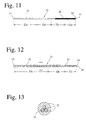
- Fig. 11 is a schematic view showing a further example of the guide wire according to the present invention;
- Fig. 12 is an enlarged cross-sectional view showing a further example of the guide wire according to the present invention;
- Fig. 13 is an A-B cross-sectional view of Fig. 12;
- Fig. 14 is a schematic view showing an example of the catheter according to the present invention;
- Fig. 15 is an enlarged A-A' cross-sectional view of Fig. 14;
- Fig. 16 is a schematic view showing another example of the catheter according to the present invention;
- Fig. 17 is an enlarged B-B' cross-sectional view of Fig. 16;
- Fig. 18 is an enlarged C-C' cross-sectional view of Fig. 16;
- Fig. 19 is a schematic view showing a further example of the catheter according to the present invention;
- Fig. 20 is a schematic view showing a further example of the PTCA catheter equipped with a balloon according to the present invention;
- Fig. 21 is an enlarged D-D' cross-sectional view of Fig. 20;
- Fig. 22 is an enlarged E-E' cross-sectional view of Fig. 20;
- Fig. 23 is a schematic view showing a further example of the catheter according to the present invention;
- Fig. 24 is an enlarged F-F' cross-sectional view of Fig. 23;
- Fig. 25 is a schematic view showing a further example of the catheter according to the present invention;
- Fig. 26 is an enlarged G-G' cross-sectional view of Fig. 25;
- Fig. 27 is a schematic view showing a further example of the catheter according to the present invention;
- Fig. 28 is a partial enlarged cross-sectional view of Fig. 27;
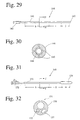
- Fig. 29 is a schematic view showing a further example of the catheter according to the present invention;
- Fig. 30 is an enlarged H-H' cross-sectional view of Fig. 29;
- Fig. 31 is a schematic view showing a further example of the catheter according to the present invention; and
- Fig. 32 is an enlarged I-I' cross-sectional view of Fig. 31.
-
- The functionally graded alloy of the present invention contains 3-10 weight % of Al, 5-20 weight % of Mn, and the balance being substantially Cu and inevitable impurities. Though the functionally graded alloy has a β-phase structure [body-centered cubic (bcc) structure] at a high temperature, a martensitic transformation without diffusion occurs at a low temperature. Specifically, the β-phase structure is changed to a dual-phase structure of an α-phase [face-centered cubic (fcc) structure] and a Heusler phase [ordered body-centered cubic (fcc) structure] by heating at about 300°C.
- When the Al content is less than 3 weight %, the β-phase cannot be formed. On the other hand, when it exceeds 10 weight %, the resultant alloy becomes extremely brittle. The preferred Al content is 6-10 weight %, though it may be changed depending on the amount of Mn.
- The inclusion of Mn makes the range of the β-phase shift toward a low Al region, thereby remarkably improving the cold workability of the alloy, which makes it easy to form the alloy. When the content of Mn is less than 5 weight %, sufficient workability cannot be obtained, failing to form the region of the β-phase. On the other hand, when the content of Mn exceeds 20 weight %, sufficient shape recovery properties cannot be obtained. The preferred content of Mn is 8-12 weight %.
- The Cu-Al-Mn alloy having the above composition has good hot- and cold-workability, achieving a cold working ratio of 20 to 90 % or more. This enables the formation of extremely thin wires, sheets, pipes, etc., which is conventionally difficult.
- In addition to the above components, the functionally graded alloy of the present invention may further contain at least one metal selected from the group consisting of Ni, Co, Fe, Ti, V, Cr, Si, Nb, Mo, W, Sn, Ag, Mg, P, Zr, Zn, B, and misch metals. These elements act to make crystal grains fine while maintaining the cold workability of the functionally graded alloy, thereby improving the strength of the alloy. The total content of these additional elements is preferably 0.001-10 weight %, particularly 0.001-5 weight %. When the total content of these elements exceeds 10 weight %, the martensitic transformation temperature of the alloy lowers, making the β-phase structure unstable.
- Ni, Co, Fe and Sn are elements effective for strengthening the matrix structure of the alloy. The preferred content is 0.001-3 weight % for each of Ni and Fe. Though Co acts to make crystal grains fine by the formation of Co-Al, an excess amount of Co reduces the toughness of the alloy. Thus, the preferred content of Co is 0.001-2 weight %. Also, the preferred content of Sn is 0.001-1 weight %.
- Ti is combined with harmful elements such as N and O to form oxynitrides. When Ti is added together with B, they form borides which function to make crystal grains fine, thereby improving the shape recovery ratio of the alloy. The preferred content of Ti is 0.001-2 weight %.
- V, Nb, Mo and Zr act to increase the hardness of the alloy, thereby improving the wear resistance of the alloy. Because these elements are not substantially dissolved in the matrix, they are deposited as bcc crystals, effective in making the crystal grains fine. The preferred content of each of V, Nb, Mo and Zr is 0.001-1 weight %.
- Cr is an element effective in maintaining the wear resistance and the corrosion resistance of the alloy. The preferred content of Cr is 0.001-2 weight %.
- Si acts to increase the corrosion resistance of the alloy. The preferred content of Si is 0.001-2 weight %.
- W acts to improve the deposition strengthening of the alloy because W is not substantially dissolved in the matrix. The preferred content of W is 0.001-1 weight %.
- Mg acts to remove harmful elements such as N and O and fix harmful S as sulfides, thereby improving the hot workability and the toughness of the alloy. However, an excess amount of Mg causes the grain boundary segregation, thereby making the alloy brittle. The preferred content of Mg is 0.001-0.5 weight %.
- P acts as a deoxidizer, improving the toughness of the alloy. The preferred content of P is 0.01-0.5 weight %.
- Zn acts to lower the shape memory treatment temperature. The preferred content of Zn is 0.001-5 weight %.
- B, which acts to make crystal grains fine, is preferably used together with Ti and Zr. The preferred content of B is 0.01-0.5 weight %.
- Misch metals act to make crystal grains fine. The preferred content of misch metals is 0.001-2 weight %.
- A melt of the copper-based alloy having the composition mentioned above is cast and formed into a desirable shape by hot rolling, cold rolling, pressing, etc. The alloy of the present invention has good hot and cold workability, achieving a cold working ratio of 20 to 90 % or more. This enables the formation of extremely thin wires, sheets, ribbons, pipes, etc. which is conventionally difficult.
- In the case of the copper-based alloy containing 8-10 weight % of Al, the α+β dual-phase structure having excellent workability is formed when the average cooling speed after hot working is 200°C/minute or less. The copper-based alloy is desirably cooled at the above speed particularly in a range of 800-400°C. If the cooling speed is faster than the above speed, the β-phase is mainly formed in the alloy, failing to obtain as high workability as when the α+β dual-phase is formed. On the other hand, in the case of the copper-based alloy containing 3-8 weight % of Al, the copper-based alloy may be composed only of a β-phase structure after hot working, and the cooling speed after hot working is not limited.
- The copper-based alloy is then subjected to a heat treatment (solution treatment) at 500°C or higher, preferably 600-900°C to transform its crystal structure to the β-phase. After heat treatment, the β-phase is frozen by rapid cooling at a rate of 50°C/second or more. The rapid cooling of the alloy is carried out by immersing in a cooling medium such as water or by forced-air cooling. When the cooling speed is lower than 50°C/second, The deposition of the α-phase takes place in the alloy, failing to maintain the alloy in a state having only the β-phase crystal structure and thus reducing the property gradient. The preferred cooling speed is 200°C/second or more.
- According to the present invention, the aging treatment of the first portion where the β-phase crystal structure is maintained is carried out at a temperature of lower than 250°C. The aging treatment of the second portion where the crystal structure is transformed into the dual-phase structure of the α- phase and the Heusler phase is carried out at 250-350°C. The aging treatment of the third portion between the first and second portions is carried out at a continuous or stepwise temperature gradient (temperature distribution) from the heating temperature of the first portion to that of the second portion.
- To meet the above conditions, the aging treatment is preferably carried out in a gradient temperature heater. Fig. 1 is a schematic view showing an example of such a gradient temperature heater. The
gradient temperature heater 1 for the aging treatment of a functionally gradedalloy rod 7 comprises afurnace pipe 2, anichrome wire 3 wound around thefurnace pipe 2, a heat-insulatingmember 4, a plurality oftemperature sensors temperature controller 6 connected to thenichrome wire 3 and thetemperature sensors wound nichrome wire 3 decides the temperature gradient in thefurnace pipe 2. To turn one end portion71 of thealloy rod 7 to a first portion composed essentially of a β-phase, thenichrome wire 3 is wound sparsely around oneend portion 21 of thefurnace pipe 2. Also, to turn theother end portion 72 of thealloy rod 7 to a second portion composed essentially of an α-phase and a Heusler phase, thewire 3 is wound densely around theother end portion 22 of thefurnace pipe 2. Thus, thefurnace pipe 2 has a temperature gradient which may be controlled by the power supply /temperature controller 6. - The heating temperature of the first portion is lower than 250°C, preferably 100-200°C. If the heating temperature of the first portion were too low, the β-phase would be unstable, making it likely for the martensitic transformation temperature to change when left at room temperature. On the other hand, when the heating temperature is 250°C or higher, the α-phase may be deposited, failing to increase the difference in properties between the first and second portions.
- The heating temperature of the second portion is 250-350°C, preferably 280-320°C. When it is lower than 250°C, the crystal structure of the second portion is not sufficiently transformed into a dual-phase structure of an α-phase and a Heusler phase, failing to increase the difference in properties between the first and second portions. On the other hand, when it is higher than 350°C, the crystal structure becomes coarse, deteriorating such properties as yield stress, hardness, etc.
- The difference in heating temperature between the first and second portions is preferably 50°C or higher, particularly 80°C or higher. When it is lower than 50°C, The difference in properties between the first and second portions becomes smaller.
- The aging treatment time in general is preferably 1-300 minutes, particularly 5-200 minutes, though it may vary depending on the composition of the functionally graded alloy. Less than 1 minute of aging would not provide sufficient aging effects. On the other hand, when the aging time is longer than 300 minutes, the alloy structure becomes too coarse to keep sufficient mechanical properties as the functionally graded material.
- In the case of the core wire for a guide wire, the copper-based alloy core wire may be subjected to an aging treatment in the following two ways: The first aging treatment is to heat the core wire uniformly at 250°C or lower, preferably 100-200°C, such that it has shape recovery properties and superelasticity uniformly.
- The second aging treatment is to heat the core wire at different temperatures, such that the core wire has gradient properties. Namely, the core wire has a high-rigidity body portion, a low-rigidity tip end portion, and an intermediate portion between them having rigidity decreasing from the high-rigidity body portion to the low-rigidity tip end portion. The high-rigidity body portion is obtained by an aging treatment at 250-350°C, preferably 280-320°C, and the low-rigidity tip end portion is obtained by an aging treatment at lower than 250°C, preferably 100-200°C. The intermediate portion between them is obtained by an aging treatment at a temperature continuously or stepwise changing from the high-rigidity body portion to the low-rigidity tip end portion. The difference in aging temperature between the high-rigidity body portion and the low-rigidity tip end portion is preferably 50°C or higher, particularly 80°C or higher.
- The functionally graded alloy of the present invention comprises a first portion composed essentially of a β-phase, a second portion composed essentially of an α-phase and a Heusler phase, and a third portion having a crystal structure continuously or stepwise changing from the first portion to the second portion.
- The term "composed essentially of a β-phase" used herein means not only a crystal structure consisting only of a β-phase, but also a crystal structure containing, in addition to the β-phase, other phases such as an α-phase, a Heusler phase, borides such as TiB and ZrB, bcc phases of V, Mo, Nb and W, and intermetallic compounds such as NiAl, CoAl, etc. in such small percentages as not to affect the superelasticity and shape recovery properties of the first portion. The total amount of the α-phase and the Heusler phase is preferably 5 volume % or less. When it exceeds 5 volume %, the superelasticity and shape recovery properties of the first portion are remarkably decreased, thereby making the gradient of properties smaller.
- Also, the term "composed essentially of a dual-phase of an α-phase and a Heusler phase" used herein means not only a crystal structure consisting of only the α-phase and the Heusler phase, but also a crystal structure containing, in addition to the α-phase and the Heusler phase, other phases such as β-phase, borides such as TiB and ZrB, bcc phases of V, Mo, Nb and W, and intermetallic compounds such as NiAl, CoAl, etc. in such small percentages as not to affect the hardness of the second portion. The amount of the β phase is preferably 10 volume % or less in the second portion.
- The term "continuously or stepwise changing crystal structure" used herein means that a volume ratio of the β-phase to [the α-phase + the Heusler phase] changes continuously or stepwise in the crystal structure. The α-phase and the Heusler phase may be gradually deposited from the β-phase by aging treatment. The higher the aging temperature, and the longer the aging time, the more the α-phase and the Heusler phase are deposited. Whether the crystal structure changes continuously or stepwise in the third portion depends upon the aging temperature distribution and the aging time. When the aging treatment is carried out at a stepwise temperature distribution for a short period of time, the resultant crystal structure changes stepwise. The boundaries between the first and third portions and between the second and third portions are not explicit in the case of the third portion having a continuously changing crystal structure. Because the properties change generally sharply in the third portion, however, the boundaries of the above three portions can relatively easily be determined from the distribution of properties.
- The first portion composed essentially of the β-phase has shape memory properties and superelasticity as described in Japanese Patent Laid-Open No. 7-62472. In contrast, the second portion is composed of a hard material resistant to bending and having completely different properties from those of the first portion. The properties change continuously or stepwise in the third portion from those of the first portion to those of the second portion. Though the distance between the first portion and the second portion (length of the third portion) may arbitrarily be set, it is preferably about 2 cm or more, particularly about 5 cm or more. It is difficult to provide the aging temperature gradient in a distance of less than 2 cm.
- With respect to some properties, differences between the first portion and the second portion will be described in detail below.
- The first portion preferably has a hardness of less than 350 Hv, and the difference in hardness between the first portion and the second portion can be made as large as 20 Hv or more, though the hardness of the alloy may vary within the above range depending on its composition.
- Because the first portion composed essentially of a β-phase has superelasticity, the yield stress (0.2% offset yield strength) of the first portion is less than 400 MPa, though it may vary within this range depending upon the composition of the alloy. The difference in yield stress between the first portion and the second portion can be made as large as 50 MPa or more.
- The first portion has excellent shape recovery properties, showing a shape recovery ratio of 80% or more, while the shape recovery ratio of the second portion is as low as less than 15%, which means substantially no shape recovery properties. The difference in shape recovery ratio between the first and second portions can be made as large as 70% or more.
- The core wire for a guide wire is constituted by a functionally graded copper-based alloy wire having at least a low-rigidity tip end portion and a high-rigidity body portion.
- In the first embodiment as shown in Fig. 7, the core wire is a straight copper-based alloy wire having a tip end portion that is not tapered. The
core wire 2 is composed of fourregions base end 3 to thetip end 4, and eachregion base end 3 to the side of thetip end 4. Each region may have an arbitrarily set length. - Such gradient-rigidity core wire may be formed, as described above, by hot working and/or cold working, keeping at 500°C or higher and rapidly quenching, and further aging treatment at different temperatures in
respective regions region 2a is preferably 250-350°C, and the aging temperature in theregion 2d is lower than 250°C. The aging temperatures in theregions regions region 2b higher than that for theregion 2c. - In the second embodiment as shown in Fig. 8, the core wire is a copper-based alloy wire composed of four
regions base end 3 to thetip end 4, with a taper from theregion 2c to thetip end 4. Rigidity decreases in eachregion base end 3 to the side of thetip end 4. Each region may have an arbitrarily set length. - Like the first embodiment, the
region 2a is a high-rigidity region, while theregion 2d is a low-rigidity region. Theregions regions region 2b higher than that of theregion 2c. Because theregion 2d has a smaller diameter in the second embodiment than in the first embodiment, the softness of the copper-based alloy in theregion 2d may be less in the second embodiment than in the first embodiment. The core wire of the second embodiment may be produced in the same manner as in the first embodiment. - In the third embodiment as shown in Fig. 9, the core wire is constituted by a
base wire 5 and acore wire 6 connected to each other. Thecore wire 6 is a copper-based alloy wire, and thebase wire 5 may be a flat ribbon made of known materials such as stainless steel. Ends of thebase wire 5 and thecore wire 6 are partially overlapped and bonded with a coil, etc. - The
core wire 6 consists of tworegions base end 7a to thetip end 7b. Theregion 6a is a high-rigidity region, while theregion 6b is a region having rigidity continuously decreasing toward thetip end 7b. Thecore wire 6 is soft (less rigid) and superelastic in the vicinity of thetip end 7b. Each region may have an arbitrarily set length. - Like the first embodiment, the
core wire 6 is provided with rigidity gradient by different aging treatment temperatures applied to respective regions. The aging temperature of theregion 6a is preferably 250-350°C. Also, the aging temperature of theregion 6b has a temperature distribution continuously lowering from thebase end 7a to thetip end 7b. The highest temperature of the above temperature distribution is preferably the same as in theregion 6a, and the lowest temperature in theregion 6b is preferably lower than 250°C. - The first catheter of the present invention is at least partially constituted by a copper-based alloy pipe. The catheter is relatively rigid in a body portion, and has low rigidity in a tip end portion. The bending modulus of the copper-based alloy pipe decreases continuously or stepwise in a direction from the base end to the tip end of the catheter, and at least a tip end portion of the copper-based alloy pipe has superelasticity. The followings are specific examples of such catheters.
- Fig. 14 shows the first example of the catheter of the present invention, and Fig. 15 is an A-A' cross-sectional view of Fig 14.
- A body of the
catheter 41 is constituted by a copper-basedalloy pipe 42, which has bending modulus decreasing continuously or stepwise from thebase end 43 to thetip end portion 44. The copper-based alloy pipe can be formed from a thicker pipe by gradually reducing its diameter by rolling or drawing. - The
pipe 42 has a high-rigidity body portion 42a, a low-rigidity, superelastictip end portion 42c and anintermediate portion 42b between them having intermediate rigidity. In each region, rigidity may be uniform or gradually changing. - Such a gradient rigidity copper-based alloy pipe can be formed by a hot working and/or cold working, keeping at 500°C or higher and rapidly quenching, and then aging treatment at different temperatures in respective regions. The aging treatment temperature is preferably 250-350°C in the
body portion 42a, and lower than 250°C in thetip end portion 42c. The aging treatment temperature in theintermediate portion 42b is between those of thebody portion 42a and thetip end portion 42c. When gradient is necessary in each region, the aging treatment temperature should gradually decrease in a direction from thebase end 43 to thetip end 44 of the catheter in each region. - Fig. 16 shows the second example of the catheter of the present invention, Fig. 17 is a B-B' cross-sectional view of Fig 16, and Fig. 18 is a C-C' cross-sectional view of Fig 16.
- A body of the
catheter 51 is constituted by a copper-basedalloy pipe 52, which has bending modulus decreasing continuously or stepwise from thebase end 53 to thetip end portion 54. The copper-basedalloy pipe 52 can be formed from a thicker pipe by gradually reducing its diameter by rolling or drawing. Thecatheter 51 may be the same as thecatheter 41 except that thetip end portion 52c is tapered. - Fig. 19 shows the third example of the catheter of the present invention. The
catheter 61 is bent at an angle of 90-150° in atip end portion 62 so that thecatheter 61 can easily enter into the winding or branched blood vessel. After bending, the copper-based alloy pipe is subjected to a solution treatment and an aging treatment. - Fig. 23 shows the second catheter of the present invention, and Fig. 24 is an F-F' cross-sectional view of Fig. 23. The
catheter 101 is constituted by aflexible tube body 111, ahub 112 mounted to a base end of theflexible tube body 111, and asoft tip 113 mounted to a tip end of theflexible tube body 111. Theflexible tube body 111 is preferably reinforced by wire- or ribbon-shaped, reinforcing copper-basedalloy members 115. - In an example shown in Fig. 24, the
tube body 111 is constituted by aninner layer 114, an intermediate Cu-Al-Mnalloy braid layer 115, and anouter layer 116. Though the intermediate Cu-Al-Mn alloy braid 115 is constituted by 8 thin Cu-Al-Mn alloy wires in Fig. 24, the number of thin wires is not restrictive. Also, a plurality of straight copper-based alloy wires may be disposed along the length of thecatheter 101. Also, the copper-based alloy wires may be in the form of coil. - The copper-based alloy reinforcing member has bending modulus decreasing continuously or stepwise from the base end to the tip end. Thus, the body portion is a high-rigidity region, the tip end portion is a low-rigidity, superelastic region, and the intermediate portion is a region having an intermediate rigidity between that of the body portion and that of the tip end portion. In each region, rigidity may be uniform or gradually changing.
- Such gradient-rigidity, reinforcing copper-based alloy member can be obtained by an aging treatment at different temperatures in respective regions in the same manner as above.
- The catheter containing the reinforcing metal member can be produced by coextrusion of a resin for the
tube body 111 and a reinforcing metal member, or by immersing aninner layer 114 coated with the reinforcingmetal member 115 in a resin solution and solidifying the resin to form anouter layer 116. - The copper-based alloy members such as core wires, guide wires and catheters are preferably coated with Au, Pt, Ti, Pd or TiN by plating or vapor deposition. Also, they are preferably coated with polyethylene, polyvinyl chloride, polyesters, polypropylene, polyamides, polyurethane, polystyrene, fluoroplastics, silicone rubbers or their elastomers, or composites thereof. These coating materials preferably contain X-ray contrast media such as barium sulfate. Further, surfaces of the core wires, the guide wires and the catheters are preferably coated with lubricating materials such as polyvinyl pyrrolidone, ethyl maleate, methyl vinyl ether-maleic anhydride copolymer, etc.
- The present invention will be described in detail below referring to the following EXAMPLES, without intention of restricting the scope of the present invention defined by the claims attached hereto.
- Copper-based alloys having compositions shown in Table 1 as Sample Nos. 1-7 (EXAMPLE 1) and Sample No. 8 (COMPARATIVE EXAMPLE 1) were melted, and solidified at a cooling rate of 140°C/minute on average to form billets each having a diameter of 20 mm. Each billet was cold-drawn a plurality of times with intermediate annealing to produce a wire having a diameter of 0.5 mm and a length of 200 mm. Each of the resultant wires was heat-treated at 900°C for 15 minutes, rapidly quenched by immersion in water with ice, and then subjected to an aging treatment by a heater shown in Fig. 1 for 15 minutes, to obtain a functionally graded alloy wire. The temperature distribution of the heater for the aging treatment is 140°C in a low-aging temperature region and 300°C in a high-aging temperature region, as shown in Fig. 2.
Compositions of Functionally graded alloys Sample Elements (weight %) No. Cu Al Mn Others 1 Bal. 8.1 9.7 - 2 Bal. 8.7 10.6 - 3 Bal. 8.7 10.8 Ti: 0.1, B: 0.05 4 Bal. 8.4 10.5 V: 0.26 5 Bal. 7.6 9.7 V: 0.45 6 Bal. 8.0 9.6 Ni: 1.0 7 Bal. 8.1 9.7 Co: 0.5 8 Bal. 8.0 9.5 Co: 2.4 - Each wire thus aging-treated was measured with respect to properties described below in a low-aging temperature portion and a high-aging temperature portion to determine property gradient thereof.
- The harness of each wire was measured both in a low-aging temperature portion and a high-aging temperature portion by a micro-Vickers hardness tester. The measurement results are shown in Table 2.
- Each wire was wound around a round rod having a diameter of 25 mm in liquid nitrogen, and measured with respect to a curvature radius R0 after taken out of the liquid nitrogen. The curved wire was then heated to 200°C to recover its original shape, and again measured with respect to a curvature radius R1. The shape recovery ratio Rs of the wire was calculated by the formula: Rs (%) = 100 × (R1 - R0) / R1. The calculated shape recovery ratios Rs are shown in Table 2.
- Each wire was subjected to a tensile test according to JIS Z 2241 to measure tensile strength, rupture elongation and yield strength (0.2% offset). The results are shown in Table 3.
Hardness and shape recovery ratio of functionally graded alloys Sample No. Hardness (Hv) Shape recovery Ratio (%) L H L H 1 240 350 83 0 2 270 380 88 0 3 235 351 90 0 4 274 360 85 0 5 280 370 81 0 6 258 372 95 0 7 239 347 94 0 8 330 391 99 0 Tensile test results of functionally graded alloys Sample No. Tensile Strength (MPa) Rupture Elongation (%) 0.2% Offset Yield Strength (MPa) L H L H L H 1 432 1129 15.4 3.2 50 807 2 699 1074 17.2 3.3 310 774 3 639 728 15.7 3.2 315 544 4 749 1147 18.2 4.6 240 745 5 272 947 13.7 7.2 63 539 6 245 1032 18.2 2.7 212 783 7 529 894 17.3 3.6 237 717 8 594 650 2.4 0.0 370 Broken - As is clear from Tables 2 and 3, the properties are remarkably different between the low-aging temperature portion and the high-aging temperature portion. For example, Sample No. 1 exhibits yield stress (0.2% offset yield strength), which is as low as 50 MPa in a low-aging temperature portion and as high as 16 times or more in a high-aging temperature portion. In Sample No. 8 (Comparative Example 1) containing an excess amount of Co, the toughness of the high-aging temperature portion is remarkably deteriorated by the deposition of Co-Al, leading to breakage.
- The wire of Sample No. 3 was divided into ten equal parts, and a center portion of each part was measured with respect to hardness. The results are plotted in Fig. 2. As is clear from Fig. 2, the hardness continuously increased from the low-aging temperature portion to the high-aging temperature portion. Particularly in the vicinity of the aging temperature of 250°C, the hardness drastically changed. It was confirmed from the change of hardness that a region extending up to about 7 cm from the low-aging temperature end had a crystal structure substantially composed of β-phase, and that a region extending up to about 7 cm from the high-aging temperature end had a dual-phase crystal structure composed essentially of an α-phase and a Heusler phase. In the intermediate region extending 6 cm between the low-aging temperature region and the high-aging temperature region, the crystal structure was gradually changing.
- The wire of Sample No. 1 was observed by an optical microscope in both low-aging temperature portion and high-aging temperature portion. Fig. 3 is an optical photomicrograph showing the microstructure of the low-aging temperature portion of the functionally graded alloy of Sample No. 1. As a result of electron diffraction analysis, it was confirmed that the crystal structure of the low-aging temperature portion was composed essentially of a β-phase. Fig. 4 is an optical photomicrograph showing the microstructure of high-aging temperature portion of the functionally graded alloy of Sample No. 1. It was also confirmed by electron diffraction that the microstructure of the high-aging temperature portion was a dual-phase structure of an α-phase and a Heusler phase.
- As a result of X-ray diffraction analysis of Sample No. 1, it was confirmed that the low-aging temperature portion was composed of 100 volume % of a β-phase, with 0 volume % of an α-phase and a Heusler phase. It was also confirmed that the high-aging temperature portion was composed of 65 volume % of an α-phase and 35 volume % of a Heusler phase, with a β-phase substantially 0 volume %.
- Copper-based alloys having compositions shown in Table 1 as Sample Nos. 2 and 3 were formed into wires each having a diameter of 0.5 mm and rapidly cooled in the same manner as in Example 1. The resultant copper-based alloy wires were then subjected to an aging treatment at 150°C, 200°C, 250°C, 300°C, 350°C and 400°C, respectively, each for 15 minutes. The hardness of the aged copper-based alloy wires was measured in the same manner as in Example 1 and plotted in Fig. 5.
- As is clear from Fig. 5, the hardness of the copper-based alloys rapidly increased when the aging temperature exceeded 250°C. However, the hardness of the copper-based alloys remarkably decreased when the aging temperature exceeded 350°C.
- Copper-based alloys having compositions shown in Table 1 as Sample Nos. 5 and 6 were formed into wires each having a diameter of 0.5 mm and rapidly cooled in the same manner as in Example 1. The resultant copper-based alloy wires were subjected to an aging treatment at 300°C for 5, 15, 60, 200, 700, 4500 and 10000 minutes, respectively. The hardness of the aged copper-based alloy wires was measured in the same manner as in Example 1 and plotted in Fig. 6.
- As is clear from Fig. 6, in Sample No. 5 containing V and Sample No. 6 containing Ni, the highest hardness was obtained for an aging time of 5-700 minutes.
- A copper-based alloy wire as shown in Fig. 7 was produced to provide a
core wire 2 for a guide wire. Thecore wire 2 had a total length of 1200 mm, and itstip end 4 was not tapered. - For this purpose, a copper-based alloy comprising 7.5 weight % of Al, 9.9 weight % of Mn, 2.0 weight % of Ni, and 80.6 weight % of Cu was melted, solidified at a cooling speed of 140°C/min. on average, and then cold-drawn to provide a wire of 0.4 mm in diameter. Thereafter, the wire was heat-treated at 900°C for 10 minutes and rapidly quenched by immersion in ice water.
- The
resultant core wire 2 was cut to 1200 mm, and subjected to an aging treatment at different temperatures in four regions from thebase end 3 to thetip end 4 for 15 minutes; at 300°C in aregion 2a of 600 mm, at 250°C in aregion 2b of 300 mm, at 200°C in aregion 2c of 200 mm, and at 150°C in aregion 2d of 100 mm, respectively. With this heat treatment, the rigidity of thecore wire 2 decreased from thebase end 3 to thetip end 4. The hardness of each region was measured by a micro-Vickers hardness tester. The measurement results are shown in Table 4.Hardness distribution Region Hardness (Hv) 2a 380 2b 290 2c 240 2d 235 - It has been found that the Cu-at least-Mn alloy composing the
core wire 2 can be provided with different properties at as small intervals as a few centimeters by heating conditions of the aging treatment. Thus, without tapering, a good balance of rigidity and softness can be achieved continuously along thecore wire 2. Also, thecore wire 2 is an integral wire made of an alloy of the same composition, which is excellent in torque conveyance. - A
guide wire 11 was produced by using a copper-based alloy wire as shown in Fig. 10 as acore wire 12. Thecore wire 12 constituted by fourregions 12a (500 mm), 12b (100 mm), 12c (50 mm) and 12d (50 mm) from thebase end 13 to thetip end 14 was tapered from the region 12c to thetip end 14, such that theregions tip end 14 had a diameter of 0.1 mm. Thecore wire 12 was subjected to the same aging treatment as in EXAMPLE 4 under the following aging conditions: at 300°C for theregion 12a, at 250°C for theregion 12b, at 200°C for the region 12c, and at 150°C for the region 12d. The aging time was 15 minutes. With this aging treatment, the rigidity of thecore wire 12 decreased from thebase end 13 to thetip end 14. - The
resultant core wire 12 was plated with gold, and coated with apolyamide elastomer layer 15 containing 40 weight % of barium sulfate as an X-ray contrast medium. Further, to improve lubrication at the time of insertion into the blood vessel, a surface of thecoating layer 15 was covered by alubricating layer 17 based on polyvinyl pyrrolidone. - A
guide wire 21 as shown in Fig. 11 was produced. Acore wire 22 constituted by fourregions 22a (500 mm), 22b (100 mm), 22c (50 mm) and 22d (50 mm) from thebase end 23 to thetip end 24 was tapered from theregion 22c to thetip end 24, such that theregions tip end 24 had a diameter of 0.1 mm. Thecore wire 22 was subjected to the same aging treatment as in EXAMPLE 4 under the following aging conditions: at 300°C for theregion 22a, at 250°C for theregion 22b, at 200°C for theregion 22c, and at 150°C for theregion 22d. The aging time was 15 minutes. With this aging treatment, the rigidity of thecore wire 22 decreased from thebase end 23 to thetip end 24. - The tapered portion of the
resultant core wire 22 was covered by acoil 26, and thetip end 24 was provided with an expandedportion 27 by a plasma welding to avoid damaging of the blood vessel walls. Thecore wire 22 and thecoil 26 were plated with gold. To improve lubrication at the time of insertion into the blood vessel, a surface of the gold plating was covered by a lubricating layer (not shown) based on polyvinyl pyrrolidone. - A
core wire 32 of aguide wire 31 as shown in Fig. 12 was a braided wire constituted by three thin copper-based alloy wires. See Fig. 13, an A-B cross section of Fig. 12. Thecore wire 32 had rigidity stepwise decreasing along aregion 32a (500 mm), aregion 32b (100 mm) and aregion 32c (50 mm) from thebase end 33 to thetip end 34. Thecore wire 32 was tapered from theregion 32c to thetip end 34, such that a diameter was 0.4 mm in theregions tip end 34. Thetip end 34 was provided with an expandedportion 36 by a plasma welding to avoid loosing of the braided wires and to improve the X-ray contrast of thetip end 34. - The
core wire 32 was subjected to the same aging treatment as in EXAMPLE 4 except for the following aging conditions: at 300°C for theregion 32a, at 250°C for theregion 32b, and at 200°C for theregion 32c. The aging time was 15 minutes. With this aging treatment, the rigidity of thecore wire 32 decreased from thebase end 33 to thetip end 34. - The
resultant core wire 32 was coated with apolyamide elastomer layer 35 containing 40 weight % of barium sulfate as an X-ray contrast medium. Further, to improve lubrication at the time of insertion into the blood vessel, a surface of thecoating layer 35 was covered by a lubricating layer (not shown) based on polymethyl vinyl ether-maleic anhydride derivative. - A catheter as shown in Figs. 14 and 15 was produced. The
catheter 41 was constituted by a superelastic Cu-Al-Mn alloy pipe 42 having an outer diameter of 1.5 mm and an inner diameter of 1.4 mm. Thepipe 42 had bending modulus decreasing stepwise from abody portion 42a to atip end portion 42c through anintermediate portion 42b, and thetip end portion 42c became gradually softer toward thetip end 44. - For this purpose, a copper-based alloy comprising 7.5 weight % of Al, 9.9 weight % of Mn, 2.0 weight % of Ni, and 80.6 weight % of Cu was melted, solidified at a cooling speed of 140°C/min. on average, and then cold-rolled to provide a pipe of 2 mm in diameter and 0.1 mm in thickness. Thereafter, the pipe was heat-treated at 900°C for 10 minutes and rapidly quenched by immersion in ice water.
- The
resultant pipe 42 was subjected to an aging treatment at different temperatures in three regions for 15 minutes; at 300°C in aregion 42a, at 250°C in aregion 42b, and at a temperature gradually decreasing from 200°C to 150°C in aregion 42c, respectively. Thepipe 42 was coated with apolyamide elastomer layer 46 containing 40 weight % of barium sulfate as an X-ray contrast medium and then with a polyvinyl pyrrolidone-based lubricating layer (not shown). - The
resultant catheter 41 was rigid in abody portion 42a and fully soft in atip end portion 42c, making sure safe use for practical applications. It is also possible to improve softness in thetip end portion 42c without tapering. Particularly in a microcatheter having a small diameter, its inner bore can be made relatively large, ensuring easy and safe injection of X-ray contrasting medium, etc. - A catheter as shown in Figs. 16-18 was produced. The
catheter 51 was constituted by a superelastic Cu-Al-Mn-V alloy pipe 52 having an outer diameter of 1.5 mm and an inner diameter of 1.4 mm. Thepipe 52 had bending modulus decreasing stepwise from abody portion 52a to atip end portion 52c through anintermediate portion 52b, and thetip end portion 52c was tapered such that it became gradually softer toward the tip end. - For this purpose, a copper-based alloy comprising 7.5 weight % of Al, 9.9 weight % of Mn, 2.0 weight % of V, and 80.6 weight % of Cu was melted, solidified at a cooling speed of 140°C/min. on average, and then cold-rolled to provide a pipe of 2 mm in diameter and 0.1 mm in thickness. Thereafter, the pipe was heat-treated at 900°C for 10 minutes and rapidly quenched by immersion in ice water.
- The
resultant pipe 52 was subjected to an aging treatment at different temperatures in three regions for 15 minutes; at 300°C in aregion 52a, at 250°C in aregion 52b, and at 150°C in aregion 52c, respectively. Thepipe 52 was then coated with apolyamide elastomer layer 56 containing 40 weight % of barium sulfate as an X-ray contrast medium. Thepipe 52 was provided with asoft tip 54 at the tip end to prevent the blood vessel walls from being damaged at the time of insertion. Like in EXAMPLE 8, thepipe 52 was coated with a polyvinyl pyrrolidone-based lubricating layer (not shown) from theintermediate portion 52b to the tip end to increase lubrication at the time of insertion into the blood vessel. - The
resultant catheter 51 was rigid in abody portion 52a and fully soft in atip end portion 52c, making sure safe use for practical applications. Because thiscatheter 51 has properties changing from thebody portion 52a to thetip end portion 52c, and because thetip end portion 52c is tapered toward the tip end, it has wide versatility in design with a rigid body portion and a soft tip end portion. - A catheter as shown in Fig. 19 was produced in the same manner as in EXAMPLE 9. The
catheter 61 was the same as in EXAMPLE 9 except that atip end portion 62 of thecatheter 61 was bent at about 120°. Thiscatheter 61 could easily be inserted into the winding or branched blood vessels. - A
PTCA catheter 71 equipped with a balloon as shown in Figs. 20-22 was produced from the same Cu-Al-Mn-Ni alloy as in EXAMPLE 8 in the same manner as in EXAMPLE 9. Thecatheter 71 was constituted by a Cu-Al-Mn-Ni alloy pipe 72 having a diameter of 2 mm and a thickness of 0.1 mm. Thepipe 72 had rigidity decreasing stepwise from abody portion 72a to atip end portion 72c through anintermediate portion 72b, and thetip end portion 72c was tapered to become gradually softer toward the tip end. - The
resultant pipe 72 was plated with gold and covered by apolyamide elastomer tube 73 in thetip end portion 72c. Theelastomer tube 73 had a through-hole 76 for allowing aballoon 75 to inflate, and a through-hole 77 extending from a halfway of thecatheter 71 to the tip end portion for allowing a guide wire to pass through. Because the Cu-Al-Mn alloy pipe 72 extends almost up to a balloon region along thecatheter 71, thecatheter 71 has full rigidity while showing excellent softness and kink resistance, ensuring safe use. - A catheter as shown in Figs. 23 and 24 was produced. The
catheter 101 was constituted by atube body 111, ahub 112 mounted to a base end of thetube body 111, and asoft tip 113 mounted to a tip end of thetube body 111. Thetube body 111 was constituted by aninner layer 114, an intermediate Cu-Al-Mnalloy braid layer 115, and anouter layer 116 as shown in Fig 24. The intermediate Cu-Al-Mn alloy braid 115 was constituted by eight 0.035-mm-thick Cu-Al-Mn alloy wires comprising 7.5 weight % of Al, 9.9 weight % of Mn, 2.0 weight % of Ni, and 80.6 weight % of Cu. The thin Cu-Al-Mn alloy wires were produced in the same manner as in EXAMPLE 9. The Cu-Al-Mn alloy braid 115 was coextruded withnylon 12 to form thecatheter 101 having the Cu-Al-Mn alloy braid 115 embedded in thetube body 111. - A catheter as shown in Figs. 25 and 26 was produced. The
catheter 102 was constituted by atube body 121, ahub 122 mounted to a base end of thetube body 121, and asoft tip 123 mounted to a tip end of thetube body 121. Thetube body 121 was constituted by aninner layer 124, an intermediate Cu-Al-Mnalloy braid layer 125, and anouter layer 126 as shown in Fig. 26. The intermediate Cu-Al-Mn-V alloy braid 125 was constituted by 32 thin Cu-Al-Mn-V alloy wires having a thickness of 0.02 mm comprising 8.0 weight % of Al, 10.2 weight % of Mn, 1.0 weight % of V, and 80.8 weight % of Cu. The Cu-Al-Mn-V alloy braid 125 was subjected to an aging treatment at 300°C in a region a, at 250°C in a region b and at 150°C in a region c for 15 minutes, so that the regions a, b and c had rigidity decreasing in this order. The Cu-Al-Mn-V alloy braid 115 was coextruded with a polyurethane resin in the same manner as in EXAMPLE 12 to form acatheter 102 having the Cu-Al-Mn-V alloy braid 125 embedded in thetube body 121. - A catheter as shown in Figs. 27 and 28 was produced. The
catheter 103 was constituted by atube body 131, ahub 132 mounted to a base end of thetube body 131, and asoft tip 133 mounted to a tip end of thetube body 131. Thetube body 131 was constituted by aninner layer 134, an intermediate Cu-Al-Mnalloy braid layer 135, and anouter layer 136 as shown in Fig. 28. The intermediate Cu-Al-Mn-V alloy braid 135 was constituted by two spirally crossing Cu-Al-Mn-V alloy ribbons each having a thickness of 0.01 mm comprising 8.0 weight % of Al, 10.2 weight % of Mn, 1.0 weight % of V, and 80.8 weight % of Cu. The Cu-Al-Mn-V alloy braid 135 was subjected to an aging treatment at temperatures shown in Table 5 below for 15 minutes so that regions d, e, f and g had rigidity decreasing in this order. The hardness of thebraid 135 in each region was measured by a micro-Vickers hardness tester. The measurement results are shown in Table 5.Region Aging Temperature (°C) Hardness (Hv) d 300 380 e 250 290 f 200 260 g 150 270 - The Cu-Al-Mn-
V alloy braid 135 was coextruded withnylon 12 in the same manner as in EXAMPLE 12 to form acatheter 103 having the Cu-Al-Mn-V alloy braid 135 embedded in thetube body 131. - A catheter as shown in Figs. 29 and 30 was produced. The
catheter 104 was constituted by atube body 141, ahub 142 mounted to a base end of thetube body 141, and asoft tip 143 mounted to a tip end of thetube body 141. Thetube body 141 was constituted by aninner layer 144, fourintermediate wires 145 made of the same Cu-Al-Mn-V alloy as in EXAMPLE 13, and anouter layer 146. The Cu-Al-Mn-V alloy wires 145 were subjected to an aging treatment at 300°C in a region h, at 250°C in a region i and at 150°C in a region j for 15 minutes, so that the regions h, i and j had rigidity decreasing stepwise in this order. Also, thecatheter 104 was tapered from a halfway of the region i to the tip end to ensure softness. - A catheter as shown in Figs. 31 and 32 was produced in the same manner as in EXAMPLE 13. The
catheter 105 was constituted by atube body 151, a Y-shapedhub 152 mounted to a base end of thetube body 151, and aballoon 154 mounted to a tip end of thetube body 151. Thetube body 151 had ahole 157 for inflating theballoon 154, a thin Cu-Al-Mn alloy wire 155 and anouter layer 156. The Cu-Al-Mn alloy wire 155 was subjected to an aging treatment at 300°C in a region k, at 250°C in a region I and at 150°C in a region m for 15 minutes, so that the regions k, I and m had rigidity decreasing stepwise in this order. Also, thecatheter 105 was tapered from a halfway of the region m to the tip end to ensure softness. - As described above in detail, the functionally graded alloy of the present invention exhibits drastically changing properties such as shape recovery properties, superelasticity, hardness, mechanical strength, etc., without mechanical working such as cutting or chemical treatment such as etching for imparting size gradient. Such a functionally graded alloy can be easily produced at low cost from a copper-based alloy composed essentially of a β-phase, by an aging treatment in a heater having a continuous or stepwise temperature gradient. The functionally graded alloy of the present invention can be formed into various shapes because of its excellent cold workability.
- When the core wire, the guide wire or the catheter is constituted by a copper-based alloy having gradient properties according to the present invention, it is provided with optimum rigidity and toughness in a body portion and proper softness in a tip end portion without mechanical or chemical working. Such core wire, guide wire or catheter is excellent in insertion operability and torque conveyance, and can be inserted and placed at a desired spot in the blood vessel without damaging walls thereof.
Claims (26)
- A functionally graded alloy having a composition comprising 3-10 weight % of Al, 5-20 weight % of Mn, the balance being substantially Cu and inevitable impurities, wherein said functionally graded alloy comprises a first portion composed essentially of a β-phase, a second portion composed essentially of an α-phase and a Heusler phase, and a third portion having a crystal structure changing continuously or stepwise from said first portion to said second portion.
- The functionally graded alloy according to claim 1, further containing at least one metal selected from the group consisting of Ni, Co, Fe, Ti, V, Cr, Si, Nb, Mo, W, Sn, Ag, Mg, P, Zr, Zn, B and misch metals in a total amount of 0.001-10 weight %.
- The functionally graded alloy according to claim 1 or 2, wherein said functionally graded alloy is produced from a copper-based alloy having a crystal structure composed essentially of a β-phase by an aging treatment comprising heating said first portion at a temperature of lower than 250°C, said second portion at a temperature of 250-350°C, and said third portion at a temperature continuously or stepwise changing from the heating temperature of said first portion to the heating temperature of said second portion.
- The functionally graded alloy according to any one of claims 1-3, wherein said first portion has hardness of 350 Hv or less, said second portion has hardness 20 Hv or more higher than that of said first portion, and said third portion has hardness continuously or stepwise changing from that of said first portion to that of said second portion.
- The functionally graded alloy according to any one of claims 1-4, wherein said first portion has a yield stress of 400 MPa or less, said second portion has a yield stress at least 50 MPa higher than that of said first portion, and said third portion has a yield stress continuously or stepwise changing from that of said first portion to that of said second portion.
- The functionally graded alloy according to any one of claims 1-5, wherein said first portion has a shape recovery ratio of 80% or more, said second portion has a shape recovery ratio of 15% or less, and said third portion has an shape recovery ratio continuously or stepwise changing from that of said first portion to that of said second portion.
- A method for producing a functionally graded alloy comprising a first portion composed essentially of a β-phase, a second portion composed essentially of an α-phase and a Heusler phase, and a third portion having a crystal structure changing continuously or stepwise from said first portion to said second portion, comprising the steps of:(a) forming a copper-based alloy having a composition comprising 3-10 weight % of Al, 5-20 weight % of Mn, the balance being substantially Cu and inevitable impurities, into a desired shape;(b) keeping said copper-based alloy at 500°C or higher and rapidly cooling it to transform a crystal structure thereof substantially to a β-phase; and(c) subjecting said copper-based alloy to an aging treatment by a heater having a temperature gradient, thereby heating said first portion to lower than 250°C, said second portion to 250-350°C, and said third portion at a temperature continuously or stepwise changing from the heating temperature of said first portion to the heating temperature of said second portion.
- The method according to claim 7, wherein said copper-based alloy further contains at least one metal selected from the group consisting of Ni, Co, Fe, Ti, V, Cr, Si, Nb, Mo, W, Sn, Ag, Mg, P, Zr, Zn, B and misch metals in a total amount of 0.001-10 weight %.
- The method according to claim 7 or 8, wherein said aging treatment is carried out for one minute or more.
- A core wire for a guide wire comprising a body portion having high rigidity and a tip end portion having a lower rigidity than that of said body portion, at least part of said core wire being made of a copper-based alloy comprising 3-10 weight % of Al, and 5-20 weight % of Mn, the balance being substantially Cu and inevitable impurities.
- The core wire for a guide wire according to claim 10, wherein said copper-based alloy wire is formed by hot working and/or cold working, kept at a temperature of 500°C or higher and rapidly quenched, and then subjected to an aging treatment at a temperature of 200°C or lower, such that it has shape recovery properties and superelasticity.
- The core wire for a guide wire according to claim 10 or 11, wherein said copper-based alloy wire comprises a high-rigidity body portion, a low-rigidity tip end portion, and an intermediate portion between said high-rigidity body portion and said low-rigidity tip end portion having rigidity continuously or stepwise decreasing from said high-rigidity body portion to said low-rigidity tip end portion.
- The core wire for a guide wire according to any one of claims 10-12, wherein said copper-based alloy wire is formed by hot working and cold working, kept at a temperature of 500°C or higher and then rapidly quenched, and further subjected to an aging treatment comprising heating said high-rigidity body portion at a temperature of 250-350°C, said tip end portion at a temperature of lower than 250°C, and an intermediate portion between said body portion and said tip end portion at a temperature continuously or stepwise changing from the heating temperature of said body portion to the heating temperature of said tip end portion.
- A guide wire comprising the core wire recited in any one of claims 10-13.
- The guide wire according to claim 14, wherein said core wire is coated with Au, Pt, Ti, Pd or TiN and/or a resin.
- A catheter at least partially constituted by a metal pipe, said metal pipe being, at least in a tip end portion, made of a copper-based alloy comprising 3-10 weight % of Al, and 5-20 weight % of Mn, the balance being substantially Cu and inevitable impurities.
- The catheter according to claim 16, wherein said metal pipe has bending modulus decreasing continuously or stepwise in a direction from the base end to the tip end of said catheter.
- The catheter according to claim 16 or 17, wherein said metal pipe is formed by hot working and/or cold working, kept at a temperature of 500°C or higher and rapidly quenched, and then subjected to an aging treatment at such a temperature distribution that decreases continuously or stepwise in a direction from the base end to the tip end of said catheter, the highest temperature being 250-350°C, and the lowest temperature being lower than 250°C in said temperature distribution.
- The catheter according to any one of claims 16-18, wherein said metal pipe has an outer diameter at least partially decreasing continuously or stepwise in a direction from the base end to the tip end of said catheter.
- The catheter according to claim 16, wherein said metal pipe is coated with Au, Pt, Ti, Pd or TiN, and/or a resin.
- A catheter containing a reinforcing metal member in at least part of a catheter tube, said reinforcing metal member being made of a copper-based alloy comprising 3-10 weight % of Al, and 5-20 weight % of Mn, the balance being substantially Cu and inevitable impurities.
- The catheter according to claim 21, wherein said reinforcing metal member has bending modulus decreasing continuously or stepwise in a direction from the base end to the tip end of said catheter.
- The catheter according to claim 21 or 22, wherein said reinforcing metal member is formed by hot working and/or cold working, kept at a temperature of 500°C or higher and rapidly quenched, and then subjected to an aging treatment at such a temperature distribution that decreases continuously or stepwise in a direction from the base end to the tip end of said catheter, the highest temperature being 250-350°C, and the lowest temperature being lower than 250°C in said temperature distribution.
- The catheter according to any one of claims 21-23, wherein said reinforcing metal member is at least one thin copper-based alloy wire extending along said catheter.
- The catheter according to any one of claims 21-24, wherein said reinforcing metal member is a braid of thin copper-based alloy wires.
- The catheter according to any one of claims 21-25, wherein said reinforcing metal member is a coil of a thin copper-based alloy wire.
Applications Claiming Priority (6)
| Application Number | Priority Date | Filing Date | Title |
|---|---|---|---|
| JP18126898A JP3344946B2 (en) | 1998-06-26 | 1998-06-26 | Functionally graded alloy and method for producing the same |
| JP18126898 | 1998-06-26 | ||
| JP18948998A JP4339940B2 (en) | 1998-07-03 | 1998-07-03 | Catheter and manufacturing method thereof |
| JP18948998 | 1998-07-03 | ||
| JP18949098 | 1998-07-03 | ||
| JP18949098A JP4339941B2 (en) | 1998-07-03 | 1998-07-03 | Guide wire core material, guide wire, and manufacturing method thereof |
Publications (3)
| Publication Number | Publication Date |
|---|---|
| EP0967293A2 true EP0967293A2 (en) | 1999-12-29 |
| EP0967293A3 EP0967293A3 (en) | 2000-11-15 |
| EP0967293B1 EP0967293B1 (en) | 2004-11-24 |
Family
ID=27324981
Family Applications (1)
| Application Number | Title | Priority Date | Filing Date |
|---|---|---|---|
| EP99305087A Expired - Lifetime EP0967293B1 (en) | 1998-06-26 | 1999-06-28 | Functionally graded alloy, use thereof and method for producing the same |
Country Status (3)
| Country | Link |
|---|---|
| US (2) | US6328822B1 (en) |
| EP (1) | EP0967293B1 (en) |
| DE (1) | DE69922086D1 (en) |
Cited By (4)
| Publication number | Priority date | Publication date | Assignee | Title |
|---|---|---|---|---|
| DE10164754B4 (en) * | 2001-07-27 | 2004-03-04 | Diehl Metall Stiftung & Co.Kg | aluminum Bronze |
| WO2004064169A1 (en) * | 2003-01-09 | 2004-07-29 | Japan As Represented By President Of Kanazawa University | Structurally gradient material and functional element including the same |
| CN101967579A (en) * | 2010-09-14 | 2011-02-09 | 苏州有色金属研究院有限公司 | New Ti-contained multielement aluminium bronze alloy material |
| CN104968814A (en) * | 2012-12-31 | 2015-10-07 | 史密斯国际有限公司 | Lower melting point binder metals |
Families Citing this family (71)
| Publication number | Priority date | Publication date | Assignee | Title |
|---|---|---|---|---|
| US6776784B2 (en) | 2001-09-06 | 2004-08-17 | Core Medical, Inc. | Clip apparatus for closing septal defects and methods of use |
| US20060052821A1 (en) | 2001-09-06 | 2006-03-09 | Ovalis, Inc. | Systems and methods for treating septal defects |
| US20080015633A1 (en) * | 2001-09-06 | 2008-01-17 | Ryan Abbott | Systems and Methods for Treating Septal Defects |
| US6702835B2 (en) | 2001-09-07 | 2004-03-09 | Core Medical, Inc. | Needle apparatus for closing septal defects and methods for using such apparatus |
| WO2003045489A1 (en) * | 2001-11-26 | 2003-06-05 | Urawa Kenkyusho Private Ltd. Co. | Guide wire and production method therefor |
| WO2003053493A2 (en) * | 2001-12-19 | 2003-07-03 | Nmt Medical, Inc. | Septal occluder and associated methods |
| US7318833B2 (en) | 2001-12-19 | 2008-01-15 | Nmt Medical, Inc. | PFO closure device with flexible thrombogenic joint and improved dislodgement resistance |
| US6702762B2 (en) * | 2001-12-27 | 2004-03-09 | Advanced Cardiovascular Systems, Inc. | Apparatus and method for joining two guide wire core materials without a hypotube |
| JP2005525843A (en) * | 2002-01-14 | 2005-09-02 | エヌエムティー メディカル インコーポレイテッド | Patent foramen ovale (PFO) occlusion method and apparatus |
| WO2003082076A2 (en) | 2002-03-25 | 2003-10-09 | Nmt Medical, Inc. | Patent foramen ovale (pfo) closure clips |
| CA2486919C (en) * | 2002-06-03 | 2011-03-15 | Nmt Medical, Inc. | Device with biological tissue scaffold for percutaneous closure of an intracardiac defect and methods thereof |
| US7431729B2 (en) | 2002-06-05 | 2008-10-07 | Nmt Medical, Inc. | Patent foramen ovale (PFO) closure device with radial and circumferential support |
| US7766820B2 (en) | 2002-10-25 | 2010-08-03 | Nmt Medical, Inc. | Expandable sheath tubing |
| EP1562653A1 (en) * | 2002-11-06 | 2005-08-17 | NMT Medical, Inc. | Medical devices utilizing modified shape memory alloy |
| EP1560525B1 (en) * | 2002-11-07 | 2009-01-14 | NMT Medical, Inc. | Patent foramen ovale (pfo) closure with magnetic force |
| AU2003294682A1 (en) * | 2002-12-09 | 2004-06-30 | Nmt Medical, Inc. | Septal closure devices |
| US6977801B2 (en) * | 2003-02-24 | 2005-12-20 | Hitachi Global Storage Technologies Netherlands B.V. | Magnetoresistive device with exchange-coupled structure having half-metallic ferromagnetic Heusler alloy in the pinned layer |
| US7658747B2 (en) * | 2003-03-12 | 2010-02-09 | Nmt Medical, Inc. | Medical device for manipulation of a medical implant |
| JP4416421B2 (en) * | 2003-03-18 | 2010-02-17 | テルモ株式会社 | Guide wire and manufacturing method thereof |
| US9861346B2 (en) | 2003-07-14 | 2018-01-09 | W. L. Gore & Associates, Inc. | Patent foramen ovale (PFO) closure device with linearly elongating petals |
| WO2005006990A2 (en) * | 2003-07-14 | 2005-01-27 | Nmt Medical, Inc. | Tubular patent foramen ovale (pfo) closure device with catch system |
| US8480706B2 (en) | 2003-07-14 | 2013-07-09 | W.L. Gore & Associates, Inc. | Tubular patent foramen ovale (PFO) closure device with catch system |
| US7963952B2 (en) | 2003-08-19 | 2011-06-21 | Wright Jr John A | Expandable sheath tubing |
| CA2538476A1 (en) * | 2003-09-11 | 2005-04-21 | Nmt Medical, Inc. | Devices, systems, and methods for suturing tissue |
| US7419498B2 (en) * | 2003-10-21 | 2008-09-02 | Nmt Medical, Inc. | Quick release knot attachment system |
| WO2005046487A1 (en) | 2003-11-06 | 2005-05-26 | Nmt Medical, Inc. | Transseptal puncture apparatus |
| US8292910B2 (en) | 2003-11-06 | 2012-10-23 | Pressure Products Medical Supplies, Inc. | Transseptal puncture apparatus |
| WO2005055834A1 (en) * | 2003-11-20 | 2005-06-23 | Nmt Medical, Inc. | Device, with electrospun fabric, for a percutaneous transluminal procedure, and methods thereof |
| US20050273119A1 (en) | 2003-12-09 | 2005-12-08 | Nmt Medical, Inc. | Double spiral patent foramen ovale closure clamp |
| US8262694B2 (en) * | 2004-01-30 | 2012-09-11 | W.L. Gore & Associates, Inc. | Devices, systems, and methods for closure of cardiac openings |
| EP1737349A1 (en) * | 2004-03-03 | 2007-01-03 | NMT Medical, Inc. | Delivery/recovery system for septal occluder |
| US20050234509A1 (en) * | 2004-03-30 | 2005-10-20 | Mmt Medical, Inc. | Center joints for PFO occluders |
| US20050267524A1 (en) * | 2004-04-09 | 2005-12-01 | Nmt Medical, Inc. | Split ends closure device |
| US8361110B2 (en) * | 2004-04-26 | 2013-01-29 | W.L. Gore & Associates, Inc. | Heart-shaped PFO closure device |
| US8759715B2 (en) | 2004-10-06 | 2014-06-24 | Lincoln Global, Inc. | Method of AC welding with cored electrode |
| US8704135B2 (en) * | 2006-01-20 | 2014-04-22 | Lincoln Global, Inc. | Synergistic welding system |
| US7842903B2 (en) * | 2005-10-31 | 2010-11-30 | Lincoln Global, Inc. | Short arc welding system |
| US7166817B2 (en) * | 2004-04-29 | 2007-01-23 | Lincoln Global, Inc. | Electric ARC welder system with waveform profile control for cored electrodes |
| US9333580B2 (en) | 2004-04-29 | 2016-05-10 | Lincoln Global, Inc. | Gas-less process and system for girth welding in high strength applications |
| US8308760B2 (en) | 2004-05-06 | 2012-11-13 | W.L. Gore & Associates, Inc. | Delivery systems and methods for PFO closure device with two anchors |
| US7842053B2 (en) * | 2004-05-06 | 2010-11-30 | Nmt Medical, Inc. | Double coil occluder |
| US7704268B2 (en) * | 2004-05-07 | 2010-04-27 | Nmt Medical, Inc. | Closure device with hinges |
| WO2005110240A1 (en) | 2004-05-07 | 2005-11-24 | Nmt Medical, Inc. | Catching mechanisms for tubular septal occluder |
| CA2581677C (en) * | 2004-09-24 | 2014-07-29 | Nmt Medical, Inc. | Occluder device double securement system for delivery/recovery of such occluder device |
| US20060096966A1 (en) * | 2004-11-08 | 2006-05-11 | Lincoln Global, Inc. | Self-shielded flux cored electrode for fracture critical applications |
| US20060122694A1 (en) * | 2004-12-03 | 2006-06-08 | Stinson Jonathan S | Medical devices and methods of making the same |
| EP1868507A1 (en) | 2005-03-18 | 2007-12-26 | NMT Medical, Inc. | Catch member for pfo occluder |
| US8071155B2 (en) * | 2005-05-05 | 2011-12-06 | Boston Scientific Scimed, Inc. | Medical devices and methods of making the same |
| US8579936B2 (en) | 2005-07-05 | 2013-11-12 | ProMed, Inc. | Centering of delivery devices with respect to a septal defect |
| US7812284B2 (en) | 2005-07-12 | 2010-10-12 | Lincoln Global, Inc. | Barium and lithium ratio for flux cored electrode |
| US7846179B2 (en) | 2005-09-01 | 2010-12-07 | Ovalis, Inc. | Suture-based systems and methods for treating septal defects |
| US20070167981A1 (en) | 2005-12-22 | 2007-07-19 | Nmt Medical, Inc. | Catch members for occluder devices |
| US7804172B2 (en) * | 2006-01-10 | 2010-09-28 | Halliburton Energy Services, Inc. | Electrical connections made with dissimilar metals |
| US8551135B2 (en) | 2006-03-31 | 2013-10-08 | W.L. Gore & Associates, Inc. | Screw catch mechanism for PFO occluder and method of use |
| JP2009532125A (en) * | 2006-03-31 | 2009-09-10 | エヌエムティー メディカル, インコーポレイティッド | Deformable flap catch mechanism for occluder equipment |
| US8870913B2 (en) | 2006-03-31 | 2014-10-28 | W.L. Gore & Associates, Inc. | Catch system with locking cap for patent foramen ovale (PFO) occluder |
| US9005242B2 (en) * | 2007-04-05 | 2015-04-14 | W.L. Gore & Associates, Inc. | Septal closure device with centering mechanism |
| WO2008131167A1 (en) | 2007-04-18 | 2008-10-30 | Nmt Medical, Inc. | Flexible catheter system |
| US20130165967A1 (en) | 2008-03-07 | 2013-06-27 | W.L. Gore & Associates, Inc. | Heart occlusion devices |
| US8956389B2 (en) | 2009-06-22 | 2015-02-17 | W. L. Gore & Associates, Inc. | Sealing device and delivery system |
| US20120029556A1 (en) | 2009-06-22 | 2012-02-02 | Masters Steven J | Sealing device and delivery system |
| US8801633B2 (en) * | 2009-08-31 | 2014-08-12 | Neometrics, Inc. | High-modulus superelastic alloy wire for medical and dental purposes |
| US8500658B2 (en) | 2010-10-28 | 2013-08-06 | Abbott Cardiovascular Systems Inc. | Nickel-titanium core guide wire |
| US9770232B2 (en) | 2011-08-12 | 2017-09-26 | W. L. Gore & Associates, Inc. | Heart occlusion devices |
| US20130240096A1 (en) * | 2012-03-16 | 2013-09-19 | Gm Global Technology Operations Llc. | Phase change graded sma actuators |
| US20130239565A1 (en) * | 2012-03-16 | 2013-09-19 | GM Global Technology Operations LLC | Spatially graded sma actuators |
| US9821145B2 (en) | 2012-03-23 | 2017-11-21 | Pressure Products Medical Supplies Inc. | Transseptal puncture apparatus and method for using the same |
| US10828019B2 (en) | 2013-01-18 | 2020-11-10 | W.L. Gore & Associates, Inc. | Sealing device and delivery system |
| EP2808873A1 (en) * | 2013-05-28 | 2014-12-03 | Nexans | Electrically conductive wire and method for its manufacture |
| US9808230B2 (en) | 2014-06-06 | 2017-11-07 | W. L. Gore & Associates, Inc. | Sealing device and delivery system |
| JP6661040B1 (en) * | 2019-03-29 | 2020-03-11 | 東京特殊電線株式会社 | Lead wire for narrow space insertion |
Citations (6)
| Publication number | Priority date | Publication date | Assignee | Title |
|---|---|---|---|---|
| US4925445A (en) * | 1983-09-16 | 1990-05-15 | Fuji Terumo Co., Ltd. | Guide wire for catheter |
| JPH0428375A (en) * | 1990-05-24 | 1992-01-30 | Nippon Zeon Co Ltd | Medical tube |
| JPH04365827A (en) * | 1991-06-13 | 1992-12-17 | Furukawa Electric Co Ltd:The | Extra-high strength fine wire and production thereof |
| JPH0762472A (en) * | 1993-08-27 | 1995-03-07 | Kiyohito Ishida | Copper-based shape memory alloy having high workability and its production |
| US5596996A (en) * | 1995-03-30 | 1997-01-28 | Medtronic, Inc. | High support nitinol tube guidewire with plastic plug transition |
| WO1998019728A1 (en) * | 1996-11-07 | 1998-05-14 | Linder Gerald S M D | Malleable introducer |
Family Cites Families (7)
| Publication number | Priority date | Publication date | Assignee | Title |
|---|---|---|---|---|
| DE2919478A1 (en) * | 1979-05-15 | 1980-11-27 | Diehl Gmbh & Co | COPPER-ZINC ALLOY AND THEIR USE |
| JPS60138032A (en) * | 1983-12-26 | 1985-07-22 | Mitsubishi Metal Corp | Cu base shape memory alloy |
| DD250952B3 (en) * | 1986-07-09 | 1993-04-29 | Rostock Dieselmotoren | MANGANE ALUMINUM MULTI-LUBRICATED BRONZE FOR HIGH-PURCHASED CONSTRUCTION PARTS |
| JP2733516B2 (en) | 1988-07-14 | 1998-03-30 | 矢崎総業株式会社 | Gas sensor |
| JPH05278158A (en) | 1992-03-31 | 1993-10-26 | Toshiba Corp | Metal-metal inclination function material |
| US5769796A (en) * | 1993-05-11 | 1998-06-23 | Target Therapeutics, Inc. | Super-elastic composite guidewire |
| JP3300684B2 (en) * | 1999-07-08 | 2002-07-08 | 清仁 石田 | Copper-based alloy having shape memory characteristics and superelasticity, member made of the same, and method of manufacturing the same |
-
1999
- 1999-06-25 US US09/339,929 patent/US6328822B1/en not_active Expired - Lifetime
- 1999-06-28 EP EP99305087A patent/EP0967293B1/en not_active Expired - Lifetime
- 1999-06-28 DE DE69922086T patent/DE69922086D1/en not_active Expired - Lifetime
-
2001
- 2001-10-23 US US09/983,069 patent/US6916386B2/en not_active Expired - Fee Related
Patent Citations (6)
| Publication number | Priority date | Publication date | Assignee | Title |
|---|---|---|---|---|
| US4925445A (en) * | 1983-09-16 | 1990-05-15 | Fuji Terumo Co., Ltd. | Guide wire for catheter |
| JPH0428375A (en) * | 1990-05-24 | 1992-01-30 | Nippon Zeon Co Ltd | Medical tube |
| JPH04365827A (en) * | 1991-06-13 | 1992-12-17 | Furukawa Electric Co Ltd:The | Extra-high strength fine wire and production thereof |
| JPH0762472A (en) * | 1993-08-27 | 1995-03-07 | Kiyohito Ishida | Copper-based shape memory alloy having high workability and its production |
| US5596996A (en) * | 1995-03-30 | 1997-01-28 | Medtronic, Inc. | High support nitinol tube guidewire with plastic plug transition |
| WO1998019728A1 (en) * | 1996-11-07 | 1998-05-14 | Linder Gerald S M D | Malleable introducer |
Non-Patent Citations (5)
| Title |
|---|
| CHEMICAL ABSTRACTS, vol. 127, no. 9, 1 September 1997 (1997-09-01) Columbus, Ohio, US; abstract no. 124857, KAINUMA, RYOSUKE ET AL: "Phase stability and mechanical properties of Cu-Al-Mn Heusler alloys" XP002117068 & SHINDO GIJUTSU KENKYU KAISHI (1996), 35, 211-215, * |
| CHEMICAL ABSTRACTS, vol. 80, no. 12, 25 March 1974 (1974-03-25) Columbus, Ohio, US; abstract no. 62692, NESTERENKO, E. G. ET AL: "Low-temperature segregation in copper-manganese-aluminum alloys with different degrees of deviation from stoichiometric composition" XP002117067 & FIZ. METAL. METALLOVED. (1973), 36(4), 702-10, * |
| PATENT ABSTRACTS OF JAPAN vol. 016, no. 194 (C-0938), 11 May 1992 (1992-05-11) & JP 04 028375 A (NIPPON ZEON CO LTD), 30 January 1992 (1992-01-30) * |
| PATENT ABSTRACTS OF JAPAN vol. 017, no. 236 (C-1057), 13 May 1993 (1993-05-13) & JP 04 365827 A (FURUKAWA ELECTRIC CO LTD:THE;OTHERS: 01), 17 December 1992 (1992-12-17) * |
| PATENT ABSTRACTS OF JAPAN vol. 1995, no. 06, 31 July 1995 (1995-07-31) -& JP 07 062472 A (KIYOHITO ISHIDA;OTHERS: 01), 7 March 1995 (1995-03-07) * |
Cited By (4)
| Publication number | Priority date | Publication date | Assignee | Title |
|---|---|---|---|---|
| DE10164754B4 (en) * | 2001-07-27 | 2004-03-04 | Diehl Metall Stiftung & Co.Kg | aluminum Bronze |
| WO2004064169A1 (en) * | 2003-01-09 | 2004-07-29 | Japan As Represented By President Of Kanazawa University | Structurally gradient material and functional element including the same |
| CN101967579A (en) * | 2010-09-14 | 2011-02-09 | 苏州有色金属研究院有限公司 | New Ti-contained multielement aluminium bronze alloy material |
| CN104968814A (en) * | 2012-12-31 | 2015-10-07 | 史密斯国际有限公司 | Lower melting point binder metals |
Also Published As
| Publication number | Publication date |
|---|---|
| EP0967293B1 (en) | 2004-11-24 |
| US6916386B2 (en) | 2005-07-12 |
| DE69922086D1 (en) | 2004-12-30 |
| EP0967293A3 (en) | 2000-11-15 |
| US6328822B1 (en) | 2001-12-11 |
| US20020043307A1 (en) | 2002-04-18 |
Similar Documents
| Publication | Publication Date | Title |
|---|---|---|
| EP0967293B1 (en) | Functionally graded alloy, use thereof and method for producing the same | |
| US5611874A (en) | Clad shape memory alloy composite structure and method | |
| US6406566B1 (en) | Copper-based alloy having shape memory properties and superelasticity, members made thereof and method for producing same | |
| US6329069B1 (en) | Composite structure and devices made from same and method | |
| US6165292A (en) | Superelastic guiding member | |
| EP2056743B1 (en) | Elongate medical device including deformable distal end | |
| CN101674861B (en) | Guide wire and stent | |
| US20070249965A1 (en) | Superelastic guiding member | |
| EP2995694A1 (en) | Cu-Al-Mn-BASED BAR MATERIAL AND PLATE MATERIAL DEMONSTRATING STABLE SUPERELASTICITY, METHOD FOR MANUFACTURING SAID BAR MATERIAL AND PLATE MATERIAL, SEISMIC CONTROL MEMBER IN WHICH SAID BAR MATERIAL AND PLATE MATERIAL ARE USED, AND SEISMIC CONTROL STRUCTURE IN WHICH SEISMIC CONTROL MEMBER IS USED | |
| WO2003039623A2 (en) | Work-hardened pseudoelastic guide wires | |
| US8529710B2 (en) | High-strength co-based alloy with enhanced workability and process for producing the same | |
| US20170088910A1 (en) | Corrosion and cracking resistant high manganese austenitic steels containing passivating elements | |
| JP4339940B2 (en) | Catheter and manufacturing method thereof | |
| EP3295969A1 (en) | Radiopaque composite wire for medical applications and method of making a radiopaque composite wire | |
| JP2007162121A (en) | Material for fine metal band for reinforcing resin material, and resin molding and medical product obtained by using the band material | |
| JP2002256395A (en) | High strength and low thermal expansion alloy having excellent twisting and alloy wire thereof | |
| JP3907177B2 (en) | Fe-based shape memory alloy and manufacturing method thereof | |
| EP1450976B1 (en) | Composite comprising a metal or alloy and a shape memory alloy | |
| JPWO2007043687A1 (en) | High-strength Co-based alloy with improved workability and method for producing the same | |
| JP7103588B2 (en) | Cu—Al—Mn-based shape memory alloy molded product having a threaded portion and its manufacturing method | |
| JP2000017395A (en) | Fe SERIES SHAPE MEMORY ALLOY AND ITS PRODUCTION | |
| JP4339941B2 (en) | Guide wire core material, guide wire, and manufacturing method thereof | |
| US20040197598A1 (en) | Stainless steel-copper clad and method for production thereof | |
| JP2000169920A (en) | Copper base alloy having shape memory characteristic and superelasticity, and its production | |
| US20060231178A1 (en) | Method of making an article of a titanium alloy by plastically deforming at room temperature and/or polishing |
Legal Events
| Date | Code | Title | Description |
|---|---|---|---|
| PUAI | Public reference made under article 153(3) epc to a published international application that has entered the european phase |
Free format text: ORIGINAL CODE: 0009012 |
|
| AK | Designated contracting states |
Kind code of ref document: A2 Designated state(s): DE FR GB |
|
| AX | Request for extension of the european patent |
Free format text: AL;LT;LV;MK;RO;SI |
|
| PUAL | Search report despatched |
Free format text: ORIGINAL CODE: 0009013 |
|
| AK | Designated contracting states |
Kind code of ref document: A3 Designated state(s): AT BE CH CY DE DK ES FI FR GB GR IE IT LI LU MC NL PT SE |
|
| AX | Request for extension of the european patent |
Free format text: AL;LT;LV;MK;RO;SI |
|
| 17P | Request for examination filed |
Effective date: 20010307 |
|
| AKX | Designation fees paid |
Free format text: DE FR GB |
|
| 17Q | First examination report despatched |
Effective date: 20020919 |
|
| GRAP | Despatch of communication of intention to grant a patent |
Free format text: ORIGINAL CODE: EPIDOSNIGR1 |
|
| GRAS | Grant fee paid |
Free format text: ORIGINAL CODE: EPIDOSNIGR3 |
|
| GRAA | (expected) grant |
Free format text: ORIGINAL CODE: 0009210 |
|
| AK | Designated contracting states |
Kind code of ref document: B1 Designated state(s): DE FR GB |
|
| PG25 | Lapsed in a contracting state [announced via postgrant information from national office to epo] |
Ref country code: FR Free format text: LAPSE BECAUSE OF FAILURE TO SUBMIT A TRANSLATION OF THE DESCRIPTION OR TO PAY THE FEE WITHIN THE PRESCRIBED TIME-LIMIT Effective date: 20041124 |
|
| REG | Reference to a national code |
Ref country code: GB Ref legal event code: FG4D |
|
| REF | Corresponds to: |
Ref document number: 69922086 Country of ref document: DE Date of ref document: 20041230 Kind code of ref document: P |
|
| PG25 | Lapsed in a contracting state [announced via postgrant information from national office to epo] |
Ref country code: DE Free format text: LAPSE BECAUSE OF FAILURE TO SUBMIT A TRANSLATION OF THE DESCRIPTION OR TO PAY THE FEE WITHIN THE PRESCRIBED TIME-LIMIT Effective date: 20050225 |
|
| PLBE | No opposition filed within time limit |
Free format text: ORIGINAL CODE: 0009261 |
|
| STAA | Information on the status of an ep patent application or granted ep patent |
Free format text: STATUS: NO OPPOSITION FILED WITHIN TIME LIMIT |
|
| 26N | No opposition filed |
Effective date: 20050825 |
|
| EN | Fr: translation not filed | ||
| PGFP | Annual fee paid to national office [announced via postgrant information from national office to epo] |
Ref country code: GB Payment date: 20180531 Year of fee payment: 20 |
|
| REG | Reference to a national code |
Ref country code: GB Ref legal event code: PE20 Expiry date: 20190627 |
|
| PG25 | Lapsed in a contracting state [announced via postgrant information from national office to epo] |
Ref country code: GB Free format text: LAPSE BECAUSE OF EXPIRATION OF PROTECTION Effective date: 20190627 |