EP0964185A2 - Geared motor, particularly for operating vehicle fittings - Google Patents
Geared motor, particularly for operating vehicle fittings Download PDFInfo
- Publication number
- EP0964185A2 EP0964185A2 EP99118176A EP99118176A EP0964185A2 EP 0964185 A2 EP0964185 A2 EP 0964185A2 EP 99118176 A EP99118176 A EP 99118176A EP 99118176 A EP99118176 A EP 99118176A EP 0964185 A2 EP0964185 A2 EP 0964185A2
- Authority
- EP
- European Patent Office
- Prior art keywords
- wall
- casing
- seal
- shaft
- annular
- Prior art date
- Legal status (The legal status is an assumption and is not a legal conclusion. Google has not performed a legal analysis and makes no representation as to the accuracy of the status listed.)
- Granted
Links
Images


Classifications
-
- H—ELECTRICITY
- H02—GENERATION; CONVERSION OR DISTRIBUTION OF ELECTRIC POWER
- H02K—DYNAMO-ELECTRIC MACHINES
- H02K7/00—Arrangements for handling mechanical energy structurally associated with dynamo-electric machines, e.g. structural association with mechanical driving motors or auxiliary dynamo-electric machines
- H02K7/08—Structural association with bearings
- H02K7/083—Structural association with bearings radially supporting the rotary shaft at both ends of the rotor
-
- E—FIXED CONSTRUCTIONS
- E05—LOCKS; KEYS; WINDOW OR DOOR FITTINGS; SAFES
- E05F—DEVICES FOR MOVING WINGS INTO OPEN OR CLOSED POSITION; CHECKS FOR WINGS; WING FITTINGS NOT OTHERWISE PROVIDED FOR, CONCERNED WITH THE FUNCTIONING OF THE WING
- E05F15/00—Power-operated mechanisms for wings
- E05F15/60—Power-operated mechanisms for wings using electrical actuators
- E05F15/603—Power-operated mechanisms for wings using electrical actuators using rotary electromotors
- E05F15/665—Power-operated mechanisms for wings using electrical actuators using rotary electromotors for vertically-sliding wings
- E05F15/689—Power-operated mechanisms for wings using electrical actuators using rotary electromotors for vertically-sliding wings specially adapted for vehicle windows
- E05F15/697—Motor units therefor, e.g. geared motors
-
- F—MECHANICAL ENGINEERING; LIGHTING; HEATING; WEAPONS; BLASTING
- F16—ENGINEERING ELEMENTS AND UNITS; GENERAL MEASURES FOR PRODUCING AND MAINTAINING EFFECTIVE FUNCTIONING OF MACHINES OR INSTALLATIONS; THERMAL INSULATION IN GENERAL
- F16H—GEARING
- F16H1/00—Toothed gearings for conveying rotary motion
- F16H1/02—Toothed gearings for conveying rotary motion without gears having orbital motion
- F16H1/04—Toothed gearings for conveying rotary motion without gears having orbital motion involving only two intermeshing members
- F16H1/12—Toothed gearings for conveying rotary motion without gears having orbital motion involving only two intermeshing members with non-parallel axes
- F16H1/16—Toothed gearings for conveying rotary motion without gears having orbital motion involving only two intermeshing members with non-parallel axes comprising worm and worm-wheel
-
- H—ELECTRICITY
- H02—GENERATION; CONVERSION OR DISTRIBUTION OF ELECTRIC POWER
- H02K—DYNAMO-ELECTRIC MACHINES
- H02K7/00—Arrangements for handling mechanical energy structurally associated with dynamo-electric machines, e.g. structural association with mechanical driving motors or auxiliary dynamo-electric machines
- H02K7/08—Structural association with bearings
- H02K7/081—Structural association with bearings specially adapted for worm gear drives
-
- H—ELECTRICITY
- H02—GENERATION; CONVERSION OR DISTRIBUTION OF ELECTRIC POWER
- H02K—DYNAMO-ELECTRIC MACHINES
- H02K7/00—Arrangements for handling mechanical energy structurally associated with dynamo-electric machines, e.g. structural association with mechanical driving motors or auxiliary dynamo-electric machines
- H02K7/10—Structural association with clutches, brakes, gears, pulleys or mechanical starters
- H02K7/116—Structural association with clutches, brakes, gears, pulleys or mechanical starters with gears
- H02K7/1163—Structural association with clutches, brakes, gears, pulleys or mechanical starters with gears where at least two gears have non-parallel axes without having orbital motion
- H02K7/1166—Structural association with clutches, brakes, gears, pulleys or mechanical starters with gears where at least two gears have non-parallel axes without having orbital motion comprising worm and worm-wheel
-
- E—FIXED CONSTRUCTIONS
- E05—LOCKS; KEYS; WINDOW OR DOOR FITTINGS; SAFES
- E05Y—INDEXING SCHEME RELATING TO HINGES OR OTHER SUSPENSION DEVICES FOR DOORS, WINDOWS OR WINGS AND DEVICES FOR MOVING WINGS INTO OPEN OR CLOSED POSITION, CHECKS FOR WINGS AND WING FITTINGS NOT OTHERWISE PROVIDED FOR, CONCERNED WITH THE FUNCTIONING OF THE WING
- E05Y2201/00—Constructional elements; Accessories therefore
- E05Y2201/40—Motors; Magnets; Springs; Weights; Accessories therefore
- E05Y2201/47—Springs; Spring tensioners
-
- E—FIXED CONSTRUCTIONS
- E05—LOCKS; KEYS; WINDOW OR DOOR FITTINGS; SAFES
- E05Y—INDEXING SCHEME RELATING TO HINGES OR OTHER SUSPENSION DEVICES FOR DOORS, WINDOWS OR WINGS AND DEVICES FOR MOVING WINGS INTO OPEN OR CLOSED POSITION, CHECKS FOR WINGS AND WING FITTINGS NOT OTHERWISE PROVIDED FOR, CONCERNED WITH THE FUNCTIONING OF THE WING
- E05Y2600/00—Mounting or coupling arrangements for elements provided for in this subclass
- E05Y2600/10—Adjustable or movable
- E05Y2600/13—Adjustable or movable by motors, magnets, springs, weights
-
- E—FIXED CONSTRUCTIONS
- E05—LOCKS; KEYS; WINDOW OR DOOR FITTINGS; SAFES
- E05Y—INDEXING SCHEME RELATING TO HINGES OR OTHER SUSPENSION DEVICES FOR DOORS, WINDOWS OR WINGS AND DEVICES FOR MOVING WINGS INTO OPEN OR CLOSED POSITION, CHECKS FOR WINGS AND WING FITTINGS NOT OTHERWISE PROVIDED FOR, CONCERNED WITH THE FUNCTIONING OF THE WING
- E05Y2800/00—Details, accessories and auxiliary operations not otherwise provided for
- E05Y2800/10—Additional functions
- E05Y2800/12—Sealing
-
- E—FIXED CONSTRUCTIONS
- E05—LOCKS; KEYS; WINDOW OR DOOR FITTINGS; SAFES
- E05Y—INDEXING SCHEME RELATING TO HINGES OR OTHER SUSPENSION DEVICES FOR DOORS, WINDOWS OR WINGS AND DEVICES FOR MOVING WINGS INTO OPEN OR CLOSED POSITION, CHECKS FOR WINGS AND WING FITTINGS NOT OTHERWISE PROVIDED FOR, CONCERNED WITH THE FUNCTIONING OF THE WING
- E05Y2800/00—Details, accessories and auxiliary operations not otherwise provided for
- E05Y2800/67—Materials; Strength alteration thereof
- E05Y2800/676—Plastics
- E05Y2800/678—Elastomers
-
- E—FIXED CONSTRUCTIONS
- E05—LOCKS; KEYS; WINDOW OR DOOR FITTINGS; SAFES
- E05Y—INDEXING SCHEME RELATING TO HINGES OR OTHER SUSPENSION DEVICES FOR DOORS, WINDOWS OR WINGS AND DEVICES FOR MOVING WINGS INTO OPEN OR CLOSED POSITION, CHECKS FOR WINGS AND WING FITTINGS NOT OTHERWISE PROVIDED FOR, CONCERNED WITH THE FUNCTIONING OF THE WING
- E05Y2900/00—Application of doors, windows, wings or fittings thereof
- E05Y2900/50—Application of doors, windows, wings or fittings thereof for vehicles
- E05Y2900/53—Application of doors, windows, wings or fittings thereof for vehicles characterised by the type of wing
- E05Y2900/55—Windows
-
- F—MECHANICAL ENGINEERING; LIGHTING; HEATING; WEAPONS; BLASTING
- F16—ENGINEERING ELEMENTS AND UNITS; GENERAL MEASURES FOR PRODUCING AND MAINTAINING EFFECTIVE FUNCTIONING OF MACHINES OR INSTALLATIONS; THERMAL INSULATION IN GENERAL
- F16H—GEARING
- F16H57/00—General details of gearing
- F16H57/02—Gearboxes; Mounting gearing therein
- F16H57/021—Shaft support structures, e.g. partition walls, bearing eyes, casing walls or covers with bearings
- F16H2057/0213—Support of worm gear shafts
-
- F—MECHANICAL ENGINEERING; LIGHTING; HEATING; WEAPONS; BLASTING
- F16—ENGINEERING ELEMENTS AND UNITS; GENERAL MEASURES FOR PRODUCING AND MAINTAINING EFFECTIVE FUNCTIONING OF MACHINES OR INSTALLATIONS; THERMAL INSULATION IN GENERAL
- F16H—GEARING
- F16H55/00—Elements with teeth or friction surfaces for conveying motion; Worms, pulleys or sheaves for gearing mechanisms
- F16H55/02—Toothed members; Worms
- F16H55/14—Construction providing resilience or vibration-damping
-
- Y—GENERAL TAGGING OF NEW TECHNOLOGICAL DEVELOPMENTS; GENERAL TAGGING OF CROSS-SECTIONAL TECHNOLOGIES SPANNING OVER SEVERAL SECTIONS OF THE IPC; TECHNICAL SUBJECTS COVERED BY FORMER USPC CROSS-REFERENCE ART COLLECTIONS [XRACs] AND DIGESTS
- Y10—TECHNICAL SUBJECTS COVERED BY FORMER USPC
- Y10T—TECHNICAL SUBJECTS COVERED BY FORMER US CLASSIFICATION
- Y10T74/00—Machine element or mechanism
- Y10T74/18—Mechanical movements
- Y10T74/18568—Reciprocating or oscillating to or from alternating rotary
- Y10T74/188—Reciprocating or oscillating to or from alternating rotary including spur gear
- Y10T74/18808—Reciprocating or oscillating to or from alternating rotary including spur gear with rack
-
- Y—GENERAL TAGGING OF NEW TECHNOLOGICAL DEVELOPMENTS; GENERAL TAGGING OF CROSS-SECTIONAL TECHNOLOGIES SPANNING OVER SEVERAL SECTIONS OF THE IPC; TECHNICAL SUBJECTS COVERED BY FORMER USPC CROSS-REFERENCE ART COLLECTIONS [XRACs] AND DIGESTS
- Y10—TECHNICAL SUBJECTS COVERED BY FORMER USPC
- Y10T—TECHNICAL SUBJECTS COVERED BY FORMER US CLASSIFICATION
- Y10T74/00—Machine element or mechanism
- Y10T74/19—Gearing
- Y10T74/19633—Yieldability in gear trains
-
- Y—GENERAL TAGGING OF NEW TECHNOLOGICAL DEVELOPMENTS; GENERAL TAGGING OF CROSS-SECTIONAL TECHNOLOGIES SPANNING OVER SEVERAL SECTIONS OF THE IPC; TECHNICAL SUBJECTS COVERED BY FORMER USPC CROSS-REFERENCE ART COLLECTIONS [XRACs] AND DIGESTS
- Y10—TECHNICAL SUBJECTS COVERED BY FORMER USPC
- Y10T—TECHNICAL SUBJECTS COVERED BY FORMER US CLASSIFICATION
- Y10T74/00—Machine element or mechanism
- Y10T74/19—Gearing
- Y10T74/19642—Directly cooperating gears
- Y10T74/19698—Spiral
- Y10T74/19828—Worm
Definitions
- the subject of the present invention is a geared motor, in particular for driving vehicle equipment, of the type defined in the preamble of claim 1.
- the gearboxes of current gearmotors include the following parts: toothed wheel, hub, lip seal, plastic cover and drum for winding a cable, by example, window regulator or pinion in sintered steel and plastic hub molded.
- This structure has a relatively large number of parts, which results in a relatively large manufacturing cost.
- Patent US 5,169,245 describes a geared motor in which the axial play is compensated by a helical spring acting on the end of the shaft induces an axial thrust with the interposition of a part which can come into abutment on a shoulder of the housing, when the spring undergoes a determined compression.
- the spring compresses under the effect of the axial force and, when the direction of rotation of the gearmotor is inverted, the energy stored in the spring is suddenly released.
- the opposite end of the armature shaft is violently pressed against the bottom of the stator, which causes a very annoying noise.
- the invention covered by this divisional application has for purpose of satisfactorily sealing between the toothed wheel and the housing wall after removing its cover to reduce the number of parts of the gearmotor.
- this reduction in the number of parts simplifies the structure of the gearmotor and reduces its cost by manufacturing.
- the geared motor comprises the characteristics of the characterizing part of claim 1.
- the gearmotor shown in Figures 1 to 4 is intended in particular to the training of vehicle equipment such as window regulator electric.
- the gearmotor also includes a one-piece shock absorber 5, housed inside the wheel 3 and mounted concentrically with the hub 6 of this, which also contains radial fins 7 coming to engage in corresponding radial notches 8 of the shock absorber 5 of elastic material, preferably elastomer.
- Chamfers 90 are provided on the edges of the notches 8.
- the damper 5 is provided on at least one of its faces with centering means in a cavity defined between the wheel 3 and the output 11. These means are, in the example described, constituted by pins 98 come from molding with the rest of the damper and protruding from its faces.
- the 98 pins ensure the above-mentioned centering and reserve the volume necessary for the shock absorber 5 to swell during its compression
- the reduction housing 2 includes a seal annular 9 and a drum 11 coaxial with the damper 5 and the wheel 3.
- This drum is intended to receive a cable in particular for a window regulator of the type cable, and constitutes the output member of the gearmotor.
- Joint 9 is made by overmolding, for example on a metal washer 40 (fig. 1A) press-fitted into the reduction housing 3.
- the seal 9 comprises at least a lip 9a in sliding contact on an inner annular wall 12 of the wheel toothed 3.
- the annular wall 12 is required by the fact that the wheel 3-hub connection 6 is outside of the latter, and not interposed between the axis 4 and the wheel 3.
- the seal could be fixed on the flange and its lip slide on the housing wall 3.
- the inner annular wall 12 protrudes slightly longitudinally with respect to the toothing of the wheel 3, in the direction of the drum 11.
- the seal 9 can be secured either with the wall 13 of the casing 2, for example by means of lugs 14 of elastic snap in the casing, and by sliding support on the periphery of the annular wall 12, either be joined to the latter by any appropriate means, for example by tight fitting in the space between the annular wall 12 and the base of the toothed wheel 23, while being in sliding support on the wall 13 of the casing 2.
- the drum 11 is provided with securing means in rotation with the damper 5.
- these means are constituted by fingers 10 of the drum 11 coming to engage in corresponding radial notches 8.
- the notches 8 can be for example six in number, three receiving 10 fingers and three receiving the fins 7. Thanks to this arrangement, the intermediate hub in material plastic of the gearmotors used until now can be removed, the damper 5 directly driving the drum 11.
- the gear motor comprises an outlet member 15 constituted by a pinion 16 produced one-piece with a hub 17 (Fig. 4) inside the annular wall 12 of the toothed wheel 3.
- the outlet member 15 is preferably made of sintered steel.
- the hub 17 is equipped with fingers 30 which engage in notches 8 and making it possible to secure the member 15 in rotation with shock absorber 5.
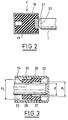
- the gearmotor is also provided with adjustment means automatic axial play between the end 1 of the armature shaft and the wall 18 of the casing 2 (Fig. 2).
- these adjustment means comprise a shock-absorbing stop 19 made of an elastic material such as rubber, filling the volume defined at this point by the wall 18, and u metal washer 21 embedded in the stopper 19. More precisely, the washer 21 is housed in the face of the stopper 19 facing the shaft 1, in such a way that the surface of the washer 21 is flush with the transverse face of the stop 19.
- the end of the shaft 1 is provided with a capsule 22 made of plastic, pressing against the washer 21.
- the assembly constituted by the shaft armature 1, its terminal capsule 22, the washer 21 and the damper 19 is mounted with a slight prestress in the wall 18, in order to compensate automatically the axial play of the shaft 1.
- the end 23 of the armature shaft opposite the stop 19 is mounted in a bearing ring 24 consisting of two radially stepped parts 25, 26.
- the first part 25 has an external diameter equal to that of the internal wall of the stator 20 on which it is supported, while its internal diameter d1 is greater than the diameter d of the shaft 23.
- the second part 26 has an internal diameter equal to that d of the shaft 23 on which it is supported, and an outside diameter d2 smaller than that of the inner wall of the stator 20.
- annular interval 27 between the end 23 of the armature shaft and part 25, and another annular gap 28 between the part 26 and stator 20.
- This stepped ring 24 significantly improves the control of the game of the shaft 23, because on its part 26 in contact with the shaft 23, the diameter does may vary since this part 26 is distant from the interval 28 of the wall inside of the stator 20. The irregularities thereof are therefore transmitted only to part 25, to which the stresses transmitted are transmitted by the part 26. Thus the oscillations of the shaft 23 are notably reduced.
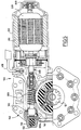
- the geared motor 100 illustrated in FIG. 5 is intended in particular training of vehicle equipment, such as electric windows.
- a stator 300 can be powered by electrical connections 400 so known, a rotor 500 provided with an armature shaft 600 whose ends are mounted in rolling bearings 700, 800.
- This armature tree bears a worm 900 in engagement with a toothed wheel 110 which can cause a output member 120, which itself drives the equipment associated with the geared motor, for example a window regulator, a sunroof ...
- these adjustment means comprise a damper 150 made of an elastic material such as an elastomer, arranged with a radial annular clearance (FIG. 6) in an end housing 170 at the end of the wall 130 of the casing 140, and a rigid stop 180 interposed between the end of the wall 130 of the casing 140, and a rigid stop 180 interposed between the end 600 a of the shaft 600 and the damper 150.
- the rigid stop 180 is of preferably metallic and forms a pellet, for example cylindrical, bearing against the end face of the damper 150, constituted for example by a cylinder made of deformable material.
- the stop 180 is also in contact with an end cap 190 fixed to the end 600 a of the armature shaft 600.
- the rigid stop 180 is axially displaceable in the casing 140 over a predetermined stroke d corresponding to the clearance axis of the shaft line between its position when carrying without load (Fig. 6) and its position under load when the gearmotor is operating (Fig. 9).
- the stroke d is limited by a stop means, constituted in the example represented by an annular transverse shoulder 210 arranged in the inner wall of the casing 140, facing the damper 150.
- the rigid stop 180 is provided with anti-rotation means around the shaft of the armature shaft 600.
- these means consist of two tabs 220 projecting radially from the periphery of the stop 180 and diametrically opposite, and which are engaged in corresponding notches 230 formed in the inner wall 130 of the casing 140.
- These notches constitute grooves 230 which extend longitudinally to the transverse plane of the shoulder 210, in order to allow sliding. legs 220 in these grooves 230 when the stop 180 travels the stroke d .
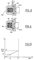
- the stop 180 Before assembly of the shaft line, the stop 180 is distant from the clearance d of the shoulder 210 (Fig. 6). After assembly of the gearmotor and without load, at rest, the shaft line 600 is in precompression with a force F1 as a function of the dimension d1 (FIG. 8), less than d . In this position, the damper 150 undergoes a precompression force of, for example, between 0 and 100 Newtons, and the remaining play or dimension d1 results from the stacking of the axial dimensions of the component parts of the gearmotor (shaft 600, stops, housing 140 , cylinder head etc.).
- the dimension or clearance d1 as well as the clearance d are illustrated in the diagram of FIG. 600, which shows that the axial force F exerted by the armature shaft 600 on the stop 180 and on the damper 150 increases linearly by F1 to F2, that is to say until the stop 180 comes to a stop against the transverse shoulder 210.
- the maximum force F2 undergone by the stop 150 at this time is for example 100 Newtons.
- This limitation prevents creep of the elastic material of the shock absorber 150, and consequently its deterioration by axial forces greater than the value F2 reached when the stop 180 abuts against the shoulder 210.
- the axial forces developed by the shaft 600 increase then suddenly (diagram in Figure 10) and are transferred directly to the shoulder 210 therefore on the wall 130 of the casing 140.
- the invention is not limited to the embodiment shown and may have various variants. So for example any anti-rotation means rigid stop 180 can be used, a single tab or lug 220 can possibly be implemented.
- the automatic compensation device for the axial play of the tree line is easy to make and therefore inexpensive, everything by having a long service life thanks to the limitation of the efforts of compression on the shock absorber 150 which prevents its deterioration as previously exposed.
- the seal 9 may have more than one lip, for example example two.
Abstract
Ce motoréducteur comprend un rotor pourvu d'un arbre d'induit (1, 23),
un carter réducteur (2), qui contient une vis sans fin en prise avec une roue
dentée (3) contenant un amortisseur (5), un organe de sortie entraíné en
rotation par l'amortisseur, des moyens d'étanchéité du carter qui comprennent
une paroi annulaire (12) de la roue dentée (3)et un joint (9) disposé entre
ladite paroi (12) et la paroi (13) du carter, ce joint étant solidarisé soit avec le
carter et en appui glissant sur la paroi annulaire, soit avec la paroi annulaire
et en appui glissant sur le carter, l'étanchéité étant réalisée entre une lèvre
(9a) au moins du joint (9) et ladite paroi annulaire ; il est caractérisé en ce
que le joint (9) est fixé à ladite paroi par une rondelle emmanchée à force
dans le carter.

Description
La présente demande est une demande divisionnaire de la demande de brevet européen n° 97.924.086.8-2306.This application is a divisional application from the European patent application no.97.924.086.8-2306.
La présente invention a pour objet un motoréducteur, notamment pour l'entraínement d'équipements de véhicules, du type défini au préambule de la revendication 1.The subject of the present invention is a geared motor, in particular for driving vehicle equipment, of the type defined in the preamble of claim 1.
Les carters réducteurs des motoréducteurs actuels comprennent les pièces suivantes :roue dentée, moyeu, joint d'étanchéité à lèvre, couvercle et tambour en matière plastique pour l'enroulement d'un câble, par exemple, de lève-vitre ou pignon en acier fritté et moyeu en matière plastique surmoulé.The gearboxes of current gearmotors include the following parts: toothed wheel, hub, lip seal, plastic cover and drum for winding a cable, by example, window regulator or pinion in sintered steel and plastic hub molded.
Cette structure comporte un nombre relativement élevé de pièces, ce qui entraíne un coût de fabrication relativement important.This structure has a relatively large number of parts, which results in a relatively large manufacturing cost.
Par ailleurs, il existe un jeu axial dans la ligne d'arbre montée dans le motoréducteur. Ce jeu axial est dû à l'empilement des dispersions des dimensions des différentes pièces au montage (arbre, butée, carter, culasse, etc.), ces différentes pièces mises bout à bout étant moins longues que leurs logements.Furthermore, there is an axial clearance in the shaft line mounted in the gearmotor. This axial play is due to the stacking of the dispersions of the dimensions of the various parts during assembly (shaft, stop, housing, cylinder head, etc.), these different pieces placed end to end being shorter than their housing.
Jusqu'à présent ce jeu axial a été compensé manuellement au moyen d'une vis logée dans l'extrémité du carter en regard du trou d'arbre d'induit, et qui est bloquée par une colle assurant en même temps l'étanchéité. Ce procédé de réglage est long à exécuter, donc onéreux et accroít le coût de fabrication du motoréducteur.So far this axial play has been compensated manually at by means of a screw housed in the end of the housing opposite the shaft hole armature, and which is blocked by an adhesive ensuring at the same time sealing. This adjustment process is long to execute, therefore expensive and increases the manufacturing cost of the gearmotor.
Le brevet USA 5.169.245 décrit un motoréducteur dans lequel le jeu axial est compensé par un ressort hélicoïdal exerçant sur l'extrémité de l'arbre d'induit une poussée axiale avec interposition d'une pièce qui peut venir en butée sur un épaulement du carter, lorsque le ressort subit une compression déterminée. Dans un tel dispositif, le ressort se comprime sous l'effet de l'effort axial et, lorsque le sens de rotation du motoréducteur est inversé, l'énergie emmagasinée dans le ressort est brusquement libérée. De ce fait, l'extrémité opposée de l'arbre d'induit est violemment plaquée contre le fond du stator, ce qui provoque un bruit très gênant.Patent US 5,169,245 describes a geared motor in which the axial play is compensated by a helical spring acting on the end of the shaft induces an axial thrust with the interposition of a part which can come into abutment on a shoulder of the housing, when the spring undergoes a determined compression. In such a device, the spring compresses under the effect of the axial force and, when the direction of rotation of the gearmotor is inverted, the energy stored in the spring is suddenly released. Of this fact, the opposite end of the armature shaft is violently pressed against the bottom of the stator, which causes a very annoying noise.
Enfin, un autre problème résulte du sertissage d'une bague entre l'arbre du motoréducteur et le stator. En effet, le diamètre intérieur de cette bague varie en raison des irrégularités du diamètre de son logement situé au fond du stator. De ce fait, le jeu radial entre l'arbre et la bague présente des irrégularités, qui entraínent des oscillations gênantes de l'arbre. Finally, another problem results from the crimping of a ring between the gearmotor shaft and the stator. Indeed, the internal diameter of this ring varies due to irregularities in the diameter of its housing located at bottom of stator. As a result, the radial clearance between the shaft and the ring presents irregularities, which cause annoying oscillations of the tree.
L'invention visée par la présente demande divisionnaire a pour but de réaliser de manière satisfaisante l'étanchéité entre la roue dentée et la paroi du carter après enlèvement de son couvercle pour réduire le nombre de pièces du motoréducteur. Subsidiairement cette réduction du nombre des pièces simplifie la structure du motoréducteur et diminue son coût de fabrication.The invention covered by this divisional application has for purpose of satisfactorily sealing between the toothed wheel and the housing wall after removing its cover to reduce the number of parts of the gearmotor. In the alternative, this reduction in the number of parts simplifies the structure of the gearmotor and reduces its cost by manufacturing.
Conformément à l'invention, le motoréducteur comporte les caractéristiques de la partie caractérisante de la revendication 1.According to the invention, the geared motor comprises the characteristics of the characterizing part of claim 1.
L'invention sera décrite en détail en référence aux dessins
annexés, qui en illustrent une forme de réalisation à titre d'exemple non
limitatif.
Le motoréducteur représenté aux figures 1 à 4 est destiné notamment à l'entraínement d'équipements de véhicules tels que lève-vitre électrique.The gearmotor shown in Figures 1 to 4 is intended in particular to the training of vehicle equipment such as window regulator electric.
Il comprend un rotor (non représenté) pourvu d'un arbre d'induit
dont on voit une extrémité 1 (figure 2), et un carter réducteur 2 qui contient
une roue dentée 3 montée sur un axe 4 perpendiculaire à l'arbre d'induit. Ce
dernier comporte une vis sans fin (non représentée) avec laquelle la roue 3
est en prise. Le motoréducteur comprend également un amortisseur monobloc
5, logé à l'intérieur de la roue 3 et monté concentriquement au moyeu 6 de
celle-ci, qui contient de plus des ailettes radiales 7 venant s'engager dans des
encoches radiales correspondantes 8 de l'amortisseur 5 en matière élastique,
de préférence élastomère. Des chanfreins 90 sont ménagés sur les bords des
encoches 8.It includes a rotor (not shown) provided with an armature shaft
one end of which is seen 1 (FIG. 2), and a
L'amortisseur 5 est pourvu sur au moins l'une de ses faces de
moyens de centrage dans une cavité délimitée entre la roue 3 et l'organe de
sortie 11. Ces moyens sont dans l'exemple décrit constitués par des tétons 98
venus de moulage avec le reste de l'amortisseur et faisant saillie de ses
faces.The damper 5 is provided on at least one of its faces with
centering means in a cavity defined between the
Les tétons 98 assurent le centrage précité et réservent le volume nécessaire au gonflement de l'amortisseur 5 lors de sa compressionThe 98 pins ensure the above-mentioned centering and reserve the volume necessary for the shock absorber 5 to swell during its compression
Enfin, le carter réducteur 2 comprend un joint d'étanchéité
annulaire 9 et un tambour 11 coaxial à l'amortisseur 5 et à la roue 3. Ce
tambour est destiné à recevoir un câble notamment pour un lève vitre du type
à câble, et constitue l'organe de sortie du motoréducteur. Le joint 9 est réalisé
par surmoulage, par exemple sur une rondelle métallique 40 (fig.1A)
emmanchée à force dans le carter réducteur 3. Le joint 9 comporte au moins
une lèvre 9a en appui glissant sur une paroi annulaire intérieure 12 de la roue
dentée 3. La paroi annulaire 12 est nécessitée par le fait que la liaison roue 3-moyeu
6 est à l'extérieur de ce dernier, et non intercalée entre l'axe 4 et la
roue 3. Finally, the
En variante, le joint pourrait être fixé sur la collerette et sa lèvre
glisser sur la paroi du carter 3.Alternatively, the seal could be fixed on the flange and its lip
slide on the
La paroi annulaire intérieure 12 fait légèrement saillie
longitudinalement par rapport à la denture de la roue 3, en direction du
tambour 11. Le joint annulaire 9 d'étanchéité disposé entre la paroi annulaire
12 et la paroi 13 du carter 2, assure ainsi l'étanchéité de ce dernier, sans
nécessiter d'ajouter un couvercle.The inner
A cet effet, le joint 9 peut être solidarisé soit avec la paroi 13 du
carter 2, par exemple au moyen de pattes 14 d'encliquetage élastique dans le
carter, et en appui glissant sur la périphérie de la paroi annulaire 12, soit être
solidarisé avec cette dernière par tout moyen approprié par exemple par
montage serrant dans l'espace situé entre la paroi annulaire 12 et la base de
la roue dentée 23, en étant alors en appui glissant sur la paroi 13 du carter 2.For this purpose, the seal 9 can be secured either with the
Le tambour 11 est pourvu de moyens de solidarisation en
rotation avec l'amortisseur 5. Dans le mode de réalisation représenté, ces
moyens sont constitués par des doigts 10 du tambour 11 venant s'engager
dans des encoches radiales correspondantes 8. Les encoches 8 peuvent être
par exemple au nombre de six, trois recevant des doigts 10 et trois recevant
les ailettes 7. Grâce à cet agencement, le moyeu intermédiaire en matière
plastique des motoréducteurs utilisés jusqu'à présent peut être supprimé,
l'amortisseur 5 entraínant directement le tambour 11.The
Dans une autre réalisation de l'invention, le motoréducteur
comporte un organe de sortie 15 constitué par un pignon 16 réalisé
monopièce avec un moyeu 17 (Fig.4) intérieur à la paroi annulaire 12 de la
roue dentée 3. L'organe de sortie 15 est réalisé de préférence en acier fritté.
Le moyeu 17 est équipé de doigts 30 venant s'engager dans des encoches
correspondantes 8 et permettant de solidariser l'organe 15 en rotation avec
l'amortisseur 5.In another embodiment of the invention, the gear motor
comprises an
Le motoréducteur est également pourvu de moyens de réglage
automatique du jeu axial entre l'extrémité 1 de l'arbre d'induit et la paroi 18 du
carter 2 (Fig.2). Dans l'exemple représenté, ces moyens de réglage
comprennent une butée amortisseuse 19 en un matériau élastique tel que du
caoutchouc, remplissant le volume défini à cet endroit par la paroi 18, et u ne
rondelle métallique 21 noyée dans la butée 19. Plus exactement la rondelle
21 est logée dans la face de la butée 19 tournée vers l'arbre 1, de telle façon
que la surface de la rondelle 21 affleure la face transversale de la butée 19. The gearmotor is also provided with adjustment means
automatic axial play between the end 1 of the armature shaft and the
L'extrémité de l'arbre 1 est munie d'une capsule 22 en matière
plastique, en appui contre la rondelle 21. L'ensemble constitué par l'arbre
d'induit 1, sa capsule terminale 22, la rondelle 21 et l'amortisseur 19 est
monté avec une légère précontrainte dans la paroi 18, afin de compenser
automatiquement le jeu axial de l'arbre 1.The end of the shaft 1 is provided with a
Suivant une particularité complémentaire du motoréducteur,
l'extrémité 23 de l'arbre d'induit opposée à la butée 19 est montée dans une
bague de roulement 24 constituée de deux parties étagées radialement 25,
26.According to a complementary feature of the geared motor,
the
La première partie 25 a un diamètre extérieur égal à celui de la
paroi intérieure du stator 20 sur laquelle elle est en appui, tandis que son
diamètre intérieur d1 est supérieur au diamètre d de l'arbre 23. La seconde
partie 26 possède un diamètre intérieur égal à celui d de l'arbre 23 sur lequel
elle est en appui, et un diamètre extérieur d2 inférieur à celui de la paroi
intérieure du stator 20.The
Ainsi sont délimités un intervalle annulaire 27 entre l'extrémité
23 de l'arbre d'induit et la partie 25, et un autre intervalle annulaire 28 entre la
partie 26 et le stator 20.Thus are delimited an
Cette bague étagée 24 améliore sensiblement la maítrise du jeu
de l'arbre 23, car sur sa partie 26 en contact avec l'arbre 23, le diamètre ne
peut varier puisque cette partie 26 est distante de l'intervalle 28 de la paroi
intérieure du stator 20. Les irrégularités de celle-ci se transmettent donc
uniquement à la partie 25, à laquelle sont transmises les contraintes subies
par la partie 26. Ainsi les oscillations de l'arbre 23 sont notablement réduites.This stepped
Le motoréducteur 100 illustré à la figure 5 est destiné notamment
à l'entraínement d'équipements de véhicules, tels que lève-vitre électriques.The geared
Il comprend, logés à l'intérieur d'un boítier 200, un stator 300
pouvant être alimenté par des connexions électriques 400 de manière
connue, un rotor 500 pourvu d'un arbre d'induit 600 dont les extrémités sont
montées dans des paliers 700, 800 de roulement. Cet arbre d'induit porte une
vis sans fin 900 en prise avec une roue dentée 110 pouvant entraíner un
organe de sortie 120, qui lui-même entraíne l'équipement associé au
motoréducteur, par exemple un lève-vitre, un toit ouvrant...It includes, housed inside a
L'extrémité 600a de l'arbre d'induit 600 traversant le palier 700,
situé au voisinage de la vis sans fin 900, coopère avec un dispositif 120 de
compensation automatique du jeu axial entre l'éxtrémité 600a et la paroi 130
du carter réducteur 140, afin d'équilibrer les efforts axiaux F développés par
l'arbre d'induit 600 pendant le fonctionnement du motoréducteur.The
Dans le mode de réalisation représenté, ces moyens de réglage
comprennent un amortisseur 150 en un matériau élastique tel qu'un
élastomère, disposé avec un jeu annulaire radial (Fig.6) dans un logement
terminal 170 de l'extrémité de la paroi 130 du carter 140, et une butée rigide
180 interposée entre l'extrémité de la paroi 130 du carter 140, et une butée
rigide 180 interposée entre l'extrémité 600a de l'arbre 600 et l'amortisseur
150. La butée rigide 180 est de préférence métallique et forme une pastille
par exemple cylindrique, en appui contre la face d'extrémité de l'amortisseur
150, constitué par exemple par un cylindre en matériau déformable. La butée
180 est d'autre part en contact avec une capsule terminale 190 fixée à
l'extrémité 600a de l'arbre d'induit 600. La butée rigide 180 est déplaçable
axialement dans le carter 140 sur une course prédéterminée d correspondant
au jeu axial de la ligne d'arbre entre sa position au report hors charge (Fig.6)
et sa position sous charge en fonctionnement du motoréducteur (Fig.9). La
course d est limitée par un moyen d'arrêt, constitué dans l'exemple représenté
par un épaulement transversal annulaire 210 agencé dans la paroi intérieure
du carter 140, en regard de l'amortisseur 150.In the embodiment shown, these adjustment means comprise a
La butée rigide 180 est pourvue de moyens antirotation autour
de l'arbre de l'arbre d'induit 600. Dans le mode de réalisation illustré à la
figure 7, ces moyens consistent en deux pattes 220 saillant radialement de la
périphérie de la butée 180 et diamétralement opposées, et qui sont engagées
dans des crantages correspondants 230 formés dans la paroi intérieure 130
du carter 140. Ces crantages constituent des rainures 230 qui s'étendent
longitudinalement jusqu'au plan transversal de l'épaulement 210, afin de
permettre le coulissement des pattes 220 dans ces rainures 230 lorsque la
butée 180 parcourt la course d.The
Le fonctionnement du dispositif de compensation automatique du jeu axial qui vient d'être décrit est le suivant.The operation of the automatic compensation device axial clearance which has just been described is as follows.
Avant assemblage de la ligne d'arbre, la butée 180 est distante
du jeu d de l'épaulement 210 (Fig.6). Après assemblage du motoréducteur et
sans charge, au repos, la ligne d'arbre 600 est en précompression avec un
effort F1 fonction de la cote d1 (figure 8), inférieure à d. Dans cette position,
l'amortisseur 150 subit un effort de précompression compris par exemple
entre 0 et 100 Newtons, et le jeu ou cote restant d1 résulte de l'empilement
des dimensions axiales des pièces constitutives du motoréducteur (arbre 600,
butées, carter 140, culasse etc.).Before assembly of the shaft line, the
La cote ou jeu d1 ainsi que le jeu d sont illustrés sur le
diagramme de la figure 600, qui montre que l'effort axial F exercé par l'arbre
d'induit 600 sur la butée 180 et sur l'amortisseur 150 croít linéairement de F1
à F2, c'est à dire jusqu'à ce que la butée 180 vienne en arrêt contre
l'épaulement transversal 210. L'effort maximum F2 subi par la butée 150 à ce
moment est par exemple de 100 Newtons.The dimension or clearance d1 as well as the clearance d are illustrated in the diagram of FIG. 600, which shows that the axial force F exerted by the
Dans le cas où le motoréducteur est en fonctionnement, lorsque
l'effort axial F sur la ligne d'arbre dépasse la valeur prédéterminée F2, la
butée métallique 180 vient donc en contact avec l'épaulement 210, lequel
limite l'effort de compression sur l'amortisseur 150 à la valeur précitée.If the gearmotor is in operation, when
the axial force F on the shaft line exceeds the predetermined value F2, the
Cette limitation évite un fluage du matériau élastique de
l'amortisseur 150, et par conséquent sa détérioration par des efforts axiaux
supérieurs à la valeur F2 atteinte lorsque la butée 180 vient en butée contre
l'épaulement 210. Les efforts axiaux développés par l'arbre 600 augmentent
alors brutalement (diagramme de la figure 10) et sont reportés directement sur
l'épaulement 210 donc sur la paroi 130 du carter 140.This limitation prevents creep of the elastic material of
the
L'invention n'est pas limitée au mode d'exécution représenté et
peut comporter diverses variantes. Ainsi par exemple tout moyen antirotation
de la butée rigide 180 peut être utilisé, une seule patte ou ergot 220 pouvant
éventuellement être mise en oeuvre.The invention is not limited to the embodiment shown and
may have various variants. So for example any anti-rotation means
Le dispositif de compensation automatique du jeu axial de la
ligne d'arbre est d'une réalisation aisée et par conséquent peu onéreuse, tout
en ayant une longue durée de vie grâce à la limitation des efforts de
compression sur l'amortisseur 150 qui évite sa détérioration comme
précédemment expose.The automatic compensation device for the axial play of the
tree line is easy to make and therefore inexpensive, everything
by having a long service life thanks to the limitation of the efforts of
compression on the
En variante, le joint 9 peut comporter plus d'une lèvre, par exemple deux.Alternatively, the seal 9 may have more than one lip, for example example two.
Claims (2)
Applications Claiming Priority (6)
| Application Number | Priority Date | Filing Date | Title |
|---|---|---|---|
| FR9605924A FR2748307B1 (en) | 1996-05-03 | 1996-05-03 | MOTOR GEARBOX, PARTICULARLY FOR DRIVING VEHICLE EQUIPMENT |
| FR9605924 | 1996-05-13 | ||
| FR9702873A FR2760912B1 (en) | 1997-03-11 | 1997-03-11 | MOTOR GEARBOX FOR DRIVING VEHICLE EQUIPMENT SUCH AS WINDOW WINDOWS, WITH AUTOMATIC COMPENSATION OF THE AXIAL SET OF ITS SHAFT LINE |
| FR9702873 | 1997-03-11 | ||
| EP97924086A EP0898666B1 (en) | 1996-05-03 | 1997-05-13 | Reducing motor, particularly for operating vehicle fittings |
| PCT/FR1997/000848 WO1997043564A2 (en) | 1996-05-03 | 1997-05-13 | Reducing motor, particularly for operating vehicle fittings |
Related Parent Applications (1)
| Application Number | Title | Priority Date | Filing Date |
|---|---|---|---|
| EP97924086A Division EP0898666B1 (en) | 1996-05-03 | 1997-05-13 | Reducing motor, particularly for operating vehicle fittings |
Publications (3)
| Publication Number | Publication Date |
|---|---|
| EP0964185A2 true EP0964185A2 (en) | 1999-12-15 |
| EP0964185A3 EP0964185A3 (en) | 2000-03-01 |
| EP0964185B1 EP0964185B1 (en) | 2004-04-14 |
Family
ID=26232709
Family Applications (4)
| Application Number | Title | Priority Date | Filing Date |
|---|---|---|---|
| EP97924086A Expired - Lifetime EP0898666B1 (en) | 1996-05-03 | 1997-05-13 | Reducing motor, particularly for operating vehicle fittings |
| EP99118174A Expired - Lifetime EP0961052B1 (en) | 1996-05-03 | 1997-05-13 | Geared motor, particularly for operating vehicle fittings |
| EP99118175A Expired - Lifetime EP0961053B8 (en) | 1996-05-03 | 1997-05-13 | Geared motor, particularly for operating vehicle fittings |
| EP99118176A Expired - Lifetime EP0964185B1 (en) | 1996-05-03 | 1997-05-13 | Geared motor, particularly for operating vehicle fittings |
Family Applications Before (3)
| Application Number | Title | Priority Date | Filing Date |
|---|---|---|---|
| EP97924086A Expired - Lifetime EP0898666B1 (en) | 1996-05-03 | 1997-05-13 | Reducing motor, particularly for operating vehicle fittings |
| EP99118174A Expired - Lifetime EP0961052B1 (en) | 1996-05-03 | 1997-05-13 | Geared motor, particularly for operating vehicle fittings |
| EP99118175A Expired - Lifetime EP0961053B8 (en) | 1996-05-03 | 1997-05-13 | Geared motor, particularly for operating vehicle fittings |
Country Status (7)
| Country | Link |
|---|---|
| US (1) | US6393929B1 (en) |
| EP (4) | EP0898666B1 (en) |
| JP (1) | JP2000510560A (en) |
| AU (1) | AU2966897A (en) |
| DE (4) | DE69721523T2 (en) |
| ES (2) | ES2197344T3 (en) |
| WO (1) | WO1997043564A2 (en) |
Cited By (1)
| Publication number | Priority date | Publication date | Assignee | Title |
|---|---|---|---|---|
| US6890279B2 (en) | 2000-06-09 | 2005-05-10 | Vkr Holding A/S | Window operator |
Families Citing this family (44)
| Publication number | Priority date | Publication date | Assignee | Title |
|---|---|---|---|---|
| FR2771469B1 (en) * | 1997-11-27 | 2000-02-04 | Meritor Light Vehicle Sys Ltd | GEAR MOTOR FOR DRIVING VEHICLE EQUIPMENT SUCH AS A WINDOW REGULATOR WITH REMOVAL OF THE AXIAL CLEARANCE OF ITS SHAFT LINE |
| EP1232423B1 (en) | 1999-11-26 | 2004-03-10 | Siemens Aktiengesellschaft | Device for detecting the axial play |
| IT248788Y1 (en) * | 1999-11-30 | 2003-02-20 | Gate Spa | DEVICE FOR THE RECOVERY OF THE AXIAL PLAY IN A GEARMOTOR. |
| DE10020901A1 (en) * | 2000-04-28 | 2001-11-22 | Diro Gmbh & Co Kg | Adjustment mechanism to set one component against another has two toothed cogwheels and an input shaft with toothed splines and splined planet wheels for a simple adjustment action with precise positioning |
| DE10115460A1 (en) * | 2000-03-30 | 2001-10-31 | Asmo Co Ltd | Drive motor for automobile window operating mechanism has synthetic resin drive housing with reinforcing housing section on opposite side of worm housing section to cog housing section |
| JP3822462B2 (en) * | 2000-07-27 | 2006-09-20 | アスモ株式会社 | Geared motor |
| US6591707B2 (en) * | 2000-07-31 | 2003-07-15 | Asmo Co., Ltd. | Geared motor having worm wheel drivingly connected to output shaft |
| DE10042405A1 (en) * | 2000-08-30 | 2002-03-21 | Bosch Gmbh Robert | bearing seat |
| DE10056133A1 (en) * | 2000-11-13 | 2002-05-23 | Zf Lenksysteme Gmbh | Electrical steering device for motor vehicles has worm wheel in elastic compensation coupling |
| FR2836506A1 (en) * | 2002-02-22 | 2003-08-29 | Meritor Light Vehicle Sys Ltd | Window lifter device of vehicle door comprises cable-winding drum that turns inside a housing about rotational axis |
| FR2836507A1 (en) * | 2002-02-22 | 2003-08-29 | Arvinmeritor Light Vehicle Sys | Window lifter device of vehicle door comprises cable-winding drum that turns inside a housing about rotational axis |
| US7098562B2 (en) * | 2003-02-10 | 2006-08-29 | Siemens Vdo Automotive Corporation | Ambidextrous electronic window lift motor |
| FR2857717A1 (en) * | 2003-07-16 | 2005-01-21 | Arvinmeritor Light Vehicle Sys | Back-geared motor wheel e.g. for vehicle window winder has pre-stressed elastically deformable collar to grip shaft |
| DE10342074B4 (en) * | 2003-09-10 | 2012-11-22 | Brose Fahrzeugteile Gmbh & Co. Kommanditgesellschaft, Coburg | Gear unit and motor-gear unit for rope windows |
| US7258036B2 (en) * | 2003-10-20 | 2007-08-21 | Siemens Vdo Automotive Corporation | Bi-directional electric motor with endplay structure |
| DE102004002847B4 (en) * | 2004-01-19 | 2013-01-10 | Ims Gear Gmbh | Automotive gear arrangement for an auxiliary vehicle transmission and method for producing such a motor vehicle gear arrangement |
| JP4385286B2 (en) * | 2004-01-29 | 2009-12-16 | 株式会社ジェイテクト | Electric power steering device |
| GB0406887D0 (en) * | 2004-03-26 | 2004-04-28 | Boc Group Plc | Gear assembly |
| EP1619341A1 (en) * | 2004-07-23 | 2006-01-25 | Siemens Aktiengesellschaft | Vehicular actuator drive with common bearing for the motor shaft and gear shaft |
| JP4215695B2 (en) * | 2004-08-26 | 2009-01-28 | 株式会社ミツバ | Actuator device |
| GB2424045A (en) * | 2005-03-07 | 2006-09-13 | John Phillip Chevalier | Centrifugal clutch which is rotationally balanced when engaged |
| DE102005045919A1 (en) * | 2005-09-26 | 2007-03-29 | Robert Bosch Gmbh | Worm gear-drive unit for use in vehicle, has compensation unit expanding in radial direction when it is in pretensioned state to enlarge outer diameter of unit and to exert pretensioning force on shaft in axial direction |
| CA2612828C (en) * | 2006-12-21 | 2016-01-12 | Hunter Douglas Industries B.V. | Adjustable drive coupling for adjacent architectural coverings |
| US20080234080A1 (en) * | 2007-03-21 | 2008-09-25 | Xinjian Fan | Motorcycle wheel isolator |
| US7651173B2 (en) * | 2007-07-03 | 2010-01-26 | The Gates Corporation | Wheel isolator coupling |
| DE102007035970A1 (en) * | 2007-07-30 | 2009-02-12 | Ims Gear Gmbh | Electric steering device for motor vehicles |
| JP5507042B2 (en) | 2007-08-10 | 2014-05-28 | 株式会社ミツバ | Vehicle window opening and closing device |
| JP5173668B2 (en) * | 2008-08-18 | 2013-04-03 | 株式会社ミツバ | Motor with reduction mechanism |
| DE102009054826A1 (en) * | 2009-12-17 | 2011-06-22 | Robert Bosch GmbH, 70469 | Electric motor, in particular for a windshield wiper drive |
| DE102010064295A1 (en) * | 2010-12-29 | 2012-07-05 | Robert Bosch Gmbh | Bearing device for a drive unit and adjusting drive with a bearing device |
| CN103006104A (en) * | 2011-09-26 | 2013-04-03 | 德昌电机(深圳)有限公司 | Food treating machine, motor assembly and bread machine |
| KR101328071B1 (en) * | 2011-11-22 | 2013-11-13 | 동양기전 주식회사 | Worm wheel for DC motor |
| CN104854382B (en) * | 2012-11-30 | 2017-11-17 | 康斯博格汽车股份公司 | Rotation shift actuator for line traffic control manual transmission |
| JP6239351B2 (en) * | 2013-05-31 | 2017-11-29 | 株式会社ミツバ | Starter |
| US10094456B2 (en) * | 2014-05-13 | 2018-10-09 | Zhejiang Jiecang Linear Motion Technology Co., Ltd. | Actuator and applications of same |
| DE102014225992A1 (en) * | 2014-12-16 | 2016-06-16 | Robert Bosch Gmbh | Transmission drive device and method for producing a transmission drive device |
| KR101627311B1 (en) * | 2015-01-12 | 2016-06-13 | 주식회사 만도 | Worm wheel of reduction gear for use in an electric power steering |
| JP2016145630A (en) * | 2015-02-09 | 2016-08-12 | 本田技研工業株式会社 | gear |
| DE102015216707B4 (en) * | 2015-06-19 | 2019-09-05 | Adient Luxembourg Holding S.À R.L. | Geared motor, device for play clearance of a shaft, and vehicle seat |
| CN109155569B (en) * | 2016-06-29 | 2021-02-12 | 株式会社美姿把 | Motor with speed reducing mechanism |
| CN109282015A (en) * | 2017-07-20 | 2019-01-29 | 威强电工业电脑股份有限公司 | It can avoid the protection structure of motor damage |
| DE102020105409A1 (en) | 2020-02-28 | 2021-09-02 | Nidec Motors & Actuators (Germany) Gmbh | Gear housing unit with polymer element for axial play compensation |
| DE102020105408A1 (en) | 2020-02-28 | 2021-09-02 | Nidec Motors & Actuators (Germany) Gmbh | Gear housing unit with stop for axial play compensation |
| JP2023109382A (en) | 2022-01-27 | 2023-08-08 | マブチモーター株式会社 | Bearing unit and motor with speed reducer |
Citations (2)
| Publication number | Priority date | Publication date | Assignee | Title |
|---|---|---|---|---|
| US5169245A (en) | 1990-05-14 | 1992-12-08 | Jidosha Denki Kogyo K.K. | Thrust bearing device |
| FR2748307A1 (en) | 1996-05-03 | 1997-11-07 | Rockwell Lvs | Geared motor, especially for operating vehicle ancillary equipment |
Family Cites Families (29)
| Publication number | Priority date | Publication date | Assignee | Title |
|---|---|---|---|---|
| US2162104A (en) * | 1936-08-05 | 1939-06-13 | Nat Oil Seal Co | Fluid seal |
| US3396556A (en) * | 1966-09-06 | 1968-08-13 | Lovejoy Flexible Coupling Comp | Flexible coupling |
| US3455174A (en) * | 1967-04-11 | 1969-07-15 | Ferro Mfg Corp | Window regulator motor and transmission housing |
| US3930566A (en) * | 1973-07-04 | 1976-01-06 | Toyota Jidosha Kogyo Kabushiki Kaisha | Device for driving a power window |
| DE2646110A1 (en) * | 1976-10-13 | 1978-04-20 | Barth Harald | Elastic claw coupling with identical halves - has rubber thrust blocks held in ring to overcome compression set effect |
| US4090746A (en) * | 1977-04-01 | 1978-05-23 | Leeds & Northrup Company | Press fit bearing retaining bearing size when inserted into support |
| US4108447A (en) * | 1977-08-12 | 1978-08-22 | Scholin Harold W | Shaft seal |
| DE2952408A1 (en) * | 1979-04-18 | 1981-07-02 | Metallwerk Max Brose Gmbh & Co, 8630 Coburg | Electric drive for vehicle window - has drive element and worm gear separated and sealed |
| US4425815A (en) * | 1980-08-29 | 1984-01-17 | Mastergear Company Limited | Wormwheels |
| US4650227B1 (en) * | 1982-08-23 | 2000-11-28 | Cajon Co | Fluid coupling |
| JPH0721289B2 (en) * | 1983-11-15 | 1995-03-08 | 松下電器産業株式会社 | Shock torque absorber for motor with worm gear |
| JPS62127545A (en) * | 1985-11-26 | 1987-06-09 | Aisin Seiki Co Ltd | Driving device for power sheet |
| EP0261525B1 (en) * | 1986-09-24 | 1990-04-18 | Siemens Aktiengesellschaft | Actuating device, especially for window regulators of motor vehicles |
| US4790672A (en) * | 1986-12-19 | 1988-12-13 | International Business Machines Corporation | Pressed sleeve bearing |
| JPH0316862Y2 (en) * | 1987-01-16 | 1991-04-10 | ||
| DE3815356A1 (en) * | 1988-05-05 | 1989-11-16 | Brose Fahrzeugteile | Worm gear for an adjustment drive in a motor vehicle, in particular a seat adjuster |
| ES2037173T3 (en) * | 1988-09-30 | 1993-06-16 | Siemens Aktiengesellschaft | ADJUSTMENT OPERATION, ESPECIALLY AUTOMOBILE WINDOW OPERATION. |
| DE3870450D1 (en) * | 1988-09-30 | 1992-05-27 | Siemens Ag | WINDOW REGULATOR DRIVE UNIT. |
| EP0388500A1 (en) * | 1989-03-23 | 1990-09-26 | Siemens Aktiengesellschaft | Pancake design adjusting drive, in particular a motor vehicle window raising actuator |
| US5062241A (en) * | 1990-03-22 | 1991-11-05 | Masco Industries, Inc. | Varying radius helical cable spool for powered vehicle door systems |
| JPH04165938A (en) * | 1990-10-26 | 1992-06-11 | Matsushita Electric Ind Co Ltd | Shock absorber for motor |
| JPH04134161U (en) * | 1991-06-04 | 1992-12-14 | 株式会社三ツ葉電機製作所 | Motor with worm reducer |
| JP2527366Y2 (en) * | 1991-06-21 | 1997-02-26 | 株式会社ミツバ | Reduction gears for electrical components |
| US5245741A (en) * | 1991-08-14 | 1993-09-21 | Federal-Mogul Corporation | Machined shaft seal with reinforcing ring |
| DE59100439D1 (en) * | 1991-11-27 | 1993-11-04 | Siemens Ag | ADJUSTMENT DRIVE, ESPECIALLY MOTOR VEHICLE ACTUATOR. |
| DE4210302C2 (en) * | 1992-03-28 | 1994-11-24 | Licentia Gmbh | Gear motor, in particular electromotive window drive or sunroof drive |
| DE9209929U1 (en) * | 1992-07-23 | 1992-09-24 | Siemens Ag, 8000 Muenchen, De | |
| DE4224626A1 (en) * | 1992-07-25 | 1994-01-27 | Brose Fahrzeugteile | Window winding gear for vehicle - incorporates ring of sound-damping material in worm wheel assembly |
| US5956998A (en) * | 1996-06-06 | 1999-09-28 | Fenelon; Paul J. | Stress reduction gear and apparatus using same |
-
1997
- 1997-05-13 DE DE69721523T patent/DE69721523T2/en not_active Expired - Lifetime
- 1997-05-13 US US09/180,690 patent/US6393929B1/en not_active Expired - Fee Related
- 1997-05-13 AU AU29668/97A patent/AU2966897A/en not_active Abandoned
- 1997-05-13 WO PCT/FR1997/000848 patent/WO1997043564A2/en active IP Right Grant
- 1997-05-13 EP EP97924086A patent/EP0898666B1/en not_active Expired - Lifetime
- 1997-05-13 DE DE69737869T patent/DE69737869T2/en not_active Expired - Lifetime
- 1997-05-13 DE DE69728692T patent/DE69728692T2/en not_active Expired - Fee Related
- 1997-05-13 EP EP99118174A patent/EP0961052B1/en not_active Expired - Lifetime
- 1997-05-13 DE DE69734070T patent/DE69734070T2/en not_active Expired - Lifetime
- 1997-05-13 ES ES97924086T patent/ES2197344T3/en not_active Expired - Lifetime
- 1997-05-13 JP JP09540597A patent/JP2000510560A/en not_active Ceased
- 1997-05-13 EP EP99118175A patent/EP0961053B8/en not_active Expired - Lifetime
- 1997-05-13 ES ES99118176T patent/ES2218919T3/en not_active Expired - Lifetime
- 1997-05-13 EP EP99118176A patent/EP0964185B1/en not_active Expired - Lifetime
Patent Citations (2)
| Publication number | Priority date | Publication date | Assignee | Title |
|---|---|---|---|---|
| US5169245A (en) | 1990-05-14 | 1992-12-08 | Jidosha Denki Kogyo K.K. | Thrust bearing device |
| FR2748307A1 (en) | 1996-05-03 | 1997-11-07 | Rockwell Lvs | Geared motor, especially for operating vehicle ancillary equipment |
Cited By (1)
| Publication number | Priority date | Publication date | Assignee | Title |
|---|---|---|---|---|
| US6890279B2 (en) | 2000-06-09 | 2005-05-10 | Vkr Holding A/S | Window operator |
Also Published As
| Publication number | Publication date |
|---|---|
| DE69734070T2 (en) | 2006-06-14 |
| EP0961053B8 (en) | 2007-09-12 |
| DE69737869D1 (en) | 2007-08-09 |
| JP2000510560A (en) | 2000-08-15 |
| DE69734070D1 (en) | 2005-09-29 |
| EP0961052A3 (en) | 2000-03-01 |
| EP0964185A3 (en) | 2000-03-01 |
| EP0961053A3 (en) | 2000-03-01 |
| EP0898666B1 (en) | 2003-05-02 |
| DE69728692D1 (en) | 2004-05-19 |
| WO1997043564A3 (en) | 1998-02-05 |
| DE69721523T2 (en) | 2004-04-08 |
| ES2197344T3 (en) | 2004-01-01 |
| DE69721523D1 (en) | 2003-06-05 |
| ES2218919T3 (en) | 2004-11-16 |
| WO1997043564A2 (en) | 1997-11-20 |
| EP0898666A2 (en) | 1999-03-03 |
| EP0964185B1 (en) | 2004-04-14 |
| EP0961053B1 (en) | 2007-06-27 |
| US6393929B1 (en) | 2002-05-28 |
| EP0961052B1 (en) | 2005-08-24 |
| DE69728692T2 (en) | 2005-04-07 |
| EP0961053A2 (en) | 1999-12-01 |
| EP0961052A2 (en) | 1999-12-01 |
| AU2966897A (en) | 1997-12-05 |
| DE69737869T2 (en) | 2008-02-28 |
Similar Documents
| Publication | Publication Date | Title |
|---|---|---|
| EP0964185B1 (en) | Geared motor, particularly for operating vehicle fittings | |
| EP1034386B1 (en) | Gear motor for driving vehicle equipment with elimination of transmission line axial play | |
| EP1399670B1 (en) | Motor vehicle starter with improved drive assembly | |
| FR3003393A1 (en) | ELECTROMAGNETIC SWITCHING DEVICE FOR STARTER | |
| FR2998937A1 (en) | GEAR REDUCER WITH SEALING PLUG ENSURING THE AXIAL RETENTION OF A RATTRAPAGE SPRING OF THE CHANGING GAME. | |
| EP1769154B1 (en) | Starter motor, particularly for a motor vehicle, provided with a friction free-wheel starter | |
| EP1399671B1 (en) | Motor vehicle starter with improved starter drive assembly | |
| FR3039617A1 (en) | TRANSMISSION HOUSING AND TRANSMISSION MODULE PROVIDED WITH SUCH A HOUSING | |
| FR2573161A1 (en) | SPEED DRIVE PULLEY WITH SEAL SEAL AROUND HUB. | |
| FR2992367A1 (en) | Starting device i.e. choke for starting internal combustion engine of vehicle, has transmission comprising axial clearance limitation unit for decreasing and/or removing axial clearance, and plastically deformable section in axial direction | |
| EP0771958B1 (en) | Axially compressible bearing for a windscreen wiper mechanism | |
| WO2003030296A2 (en) | Rotor for vane pump | |
| FR2797109A1 (en) | Automobile starter motor has two part axially aligned housing with low axial play in inductor shaft | |
| FR2516878A1 (en) | WIPER PIVOT | |
| FR2997457A1 (en) | FRICTION FRICTION LAUNCHER WITH A STARTING CROWN OF A THERMAL MOTOR AND STARTER OF A CORRESPONDING THERMAL MOTOR | |
| FR3004222A1 (en) | IMPROVED PENCIL ASSEMBLY, LAUNCHER, AND STARTER FOR CORRESPONDING MOTOR VEHICLE | |
| EP1592881B1 (en) | Method of mounting a retaining ring on an electric starter shaft comprising a starter drive assembly and corresponding starter | |
| EP1155932A1 (en) | Bearing for guiding and axial positioning a rotating shaft | |
| FR2800422A1 (en) | STARTER EQUIPPED WITH AN IMPROVED LEVER SUPPORT PART | |
| EP1778970A1 (en) | Starter, in particular for motor vehicle, equipped with a friction-driven free-wheel drive assembly | |
| FR2681911A1 (en) | Stop (thrust) device for a starter for an internal combustion engine, and method for implementing such a device | |
| FR2748307A1 (en) | Geared motor, especially for operating vehicle ancillary equipment | |
| FR2760912A1 (en) | Geared motor, especially for operating vehicle ancillary equipment | |
| FR2738298A1 (en) | STARTER FOR A MOTOR VEHICLE ENGINE COMPRISING IMPROVED SEALING MEANS | |
| FR2744767A1 (en) | MOTOR VEHICLE STARTER PROVIDED WITH A STARTER GEAR AND METHOD FOR MOUNTING SUCH A STARTER |
Legal Events
| Date | Code | Title | Description |
|---|---|---|---|
| PUAI | Public reference made under article 153(3) epc to a published international application that has entered the european phase |
Free format text: ORIGINAL CODE: 0009012 |
|
| 17P | Request for examination filed |
Effective date: 19990913 |
|
| AC | Divisional application: reference to earlier application |
Ref document number: 898666 Country of ref document: EP |
|
| AK | Designated contracting states |
Kind code of ref document: A2 Designated state(s): DE ES GB IT |
|
| PUAL | Search report despatched |
Free format text: ORIGINAL CODE: 0009013 |
|
| AK | Designated contracting states |
Kind code of ref document: A3 Designated state(s): DE ES GB IT |
|
| RIC1 | Information provided on ipc code assigned before grant |
Free format text: 7F 16H 1/16 A, 7H 02K 7/08 B, 7H 02K 7/116 B, 7E 05F 15/16 B |
|
| RIN1 | Information on inventor provided before grant (corrected) |
Inventor name: LAURANDEL, HERVE Inventor name: QUERE, JEROME |
|
| AKX | Designation fees paid |
Free format text: DE ES GB IT |
|
| GRAP | Despatch of communication of intention to grant a patent |
Free format text: ORIGINAL CODE: EPIDOSNIGR1 |
|
| GRAS | Grant fee paid |
Free format text: ORIGINAL CODE: EPIDOSNIGR3 |
|
| GRAA | (expected) grant |
Free format text: ORIGINAL CODE: 0009210 |
|
| RAP1 | Party data changed (applicant data changed or rights of an application transferred) |
Owner name: ARVINMERITOR LIGHT VEHICLE SYSTEMS-FRANCE |
|
| AC | Divisional application: reference to earlier application |
Ref document number: 0898666 Country of ref document: EP Kind code of ref document: P |
|
| AK | Designated contracting states |
Kind code of ref document: B1 Designated state(s): DE ES GB IT |
|
| REG | Reference to a national code |
Ref country code: GB Ref legal event code: FG4D Free format text: NOT ENGLISH |
|
| REF | Corresponds to: |
Ref document number: 69728692 Country of ref document: DE Date of ref document: 20040519 Kind code of ref document: P |
|
| GBT | Gb: translation of ep patent filed (gb section 77(6)(a)/1977) |
Effective date: 20040803 |
|
| REG | Reference to a national code |
Ref country code: ES Ref legal event code: FG2A Ref document number: 2218919 Country of ref document: ES Kind code of ref document: T3 |
|
| PLBE | No opposition filed within time limit |
Free format text: ORIGINAL CODE: 0009261 |
|
| STAA | Information on the status of an ep patent application or granted ep patent |
Free format text: STATUS: NO OPPOSITION FILED WITHIN TIME LIMIT |
|
| 26N | No opposition filed |
Effective date: 20050117 |
|
| PGFP | Annual fee paid to national office [announced via postgrant information from national office to epo] |
Ref country code: GB Payment date: 20050504 Year of fee payment: 9 |
|
| PGFP | Annual fee paid to national office [announced via postgrant information from national office to epo] |
Ref country code: ES Payment date: 20050609 Year of fee payment: 9 |
|
| PG25 | Lapsed in a contracting state [announced via postgrant information from national office to epo] |
Ref country code: GB Free format text: LAPSE BECAUSE OF NON-PAYMENT OF DUE FEES Effective date: 20060513 |
|
| PG25 | Lapsed in a contracting state [announced via postgrant information from national office to epo] |
Ref country code: ES Free format text: LAPSE BECAUSE OF NON-PAYMENT OF DUE FEES Effective date: 20060516 |
|
| PGFP | Annual fee paid to national office [announced via postgrant information from national office to epo] |
Ref country code: IT Payment date: 20060531 Year of fee payment: 10 |
|
| GBPC | Gb: european patent ceased through non-payment of renewal fee |
Effective date: 20060513 |
|
| PGFP | Annual fee paid to national office [announced via postgrant information from national office to epo] |
Ref country code: DE Payment date: 20070510 Year of fee payment: 11 |
|
| REG | Reference to a national code |
Ref country code: ES Ref legal event code: FD2A Effective date: 20060516 |
|
| PG25 | Lapsed in a contracting state [announced via postgrant information from national office to epo] |
Ref country code: DE Free format text: LAPSE BECAUSE OF NON-PAYMENT OF DUE FEES Effective date: 20081202 |
|
| PG25 | Lapsed in a contracting state [announced via postgrant information from national office to epo] |
Ref country code: IT Free format text: LAPSE BECAUSE OF NON-PAYMENT OF DUE FEES Effective date: 20070513 |