EP0963122B1 - Stereoscopic imaging system - Google Patents
Stereoscopic imaging system Download PDFInfo
- Publication number
- EP0963122B1 EP0963122B1 EP99303904A EP99303904A EP0963122B1 EP 0963122 B1 EP0963122 B1 EP 0963122B1 EP 99303904 A EP99303904 A EP 99303904A EP 99303904 A EP99303904 A EP 99303904A EP 0963122 B1 EP0963122 B1 EP 0963122B1
- Authority
- EP
- European Patent Office
- Prior art keywords
- fatigue
- image
- degree
- parallax
- stereoscopic
- Prior art date
- Legal status (The legal status is an assumption and is not a legal conclusion. Google has not performed a legal analysis and makes no representation as to the accuracy of the status listed.)
- Expired - Lifetime
Links
Images


Classifications
-
- H—ELECTRICITY
- H04—ELECTRIC COMMUNICATION TECHNIQUE
- H04N—PICTORIAL COMMUNICATION, e.g. TELEVISION
- H04N13/00—Stereoscopic video systems; Multi-view video systems; Details thereof
- H04N13/20—Image signal generators
- H04N13/261—Image signal generators with monoscopic-to-stereoscopic image conversion
-
- H—ELECTRICITY
- H04—ELECTRIC COMMUNICATION TECHNIQUE
- H04N—PICTORIAL COMMUNICATION, e.g. TELEVISION
- H04N13/00—Stereoscopic video systems; Multi-view video systems; Details thereof
- H04N13/10—Processing, recording or transmission of stereoscopic or multi-view image signals
- H04N13/106—Processing image signals
- H04N13/111—Transformation of image signals corresponding to virtual viewpoints, e.g. spatial image interpolation
-
- H—ELECTRICITY
- H04—ELECTRIC COMMUNICATION TECHNIQUE
- H04N—PICTORIAL COMMUNICATION, e.g. TELEVISION
- H04N13/00—Stereoscopic video systems; Multi-view video systems; Details thereof
- H04N13/10—Processing, recording or transmission of stereoscopic or multi-view image signals
- H04N13/106—Processing image signals
- H04N13/122—Improving the 3D impression of stereoscopic images by modifying image signal contents, e.g. by filtering or adding monoscopic depth cues
-
- H—ELECTRICITY
- H04—ELECTRIC COMMUNICATION TECHNIQUE
- H04N—PICTORIAL COMMUNICATION, e.g. TELEVISION
- H04N13/00—Stereoscopic video systems; Multi-view video systems; Details thereof
- H04N13/10—Processing, recording or transmission of stereoscopic or multi-view image signals
- H04N13/106—Processing image signals
- H04N13/144—Processing image signals for flicker reduction
-
- H—ELECTRICITY
- H04—ELECTRIC COMMUNICATION TECHNIQUE
- H04N—PICTORIAL COMMUNICATION, e.g. TELEVISION
- H04N13/00—Stereoscopic video systems; Multi-view video systems; Details thereof
- H04N13/30—Image reproducers
- H04N13/356—Image reproducers having separate monoscopic and stereoscopic modes
- H04N13/359—Switching between monoscopic and stereoscopic modes
-
- H—ELECTRICITY
- H04—ELECTRIC COMMUNICATION TECHNIQUE
- H04N—PICTORIAL COMMUNICATION, e.g. TELEVISION
- H04N13/00—Stereoscopic video systems; Multi-view video systems; Details thereof
- H04N13/10—Processing, recording or transmission of stereoscopic or multi-view image signals
- H04N13/189—Recording image signals; Reproducing recorded image signals
-
- H—ELECTRICITY
- H04—ELECTRIC COMMUNICATION TECHNIQUE
- H04N—PICTORIAL COMMUNICATION, e.g. TELEVISION
- H04N13/00—Stereoscopic video systems; Multi-view video systems; Details thereof
- H04N13/10—Processing, recording or transmission of stereoscopic or multi-view image signals
- H04N13/194—Transmission of image signals
-
- H—ELECTRICITY
- H04—ELECTRIC COMMUNICATION TECHNIQUE
- H04N—PICTORIAL COMMUNICATION, e.g. TELEVISION
- H04N13/00—Stereoscopic video systems; Multi-view video systems; Details thereof
- H04N13/30—Image reproducers
- H04N13/332—Displays for viewing with the aid of special glasses or head-mounted displays [HMD]
-
- H—ELECTRICITY
- H04—ELECTRIC COMMUNICATION TECHNIQUE
- H04N—PICTORIAL COMMUNICATION, e.g. TELEVISION
- H04N13/00—Stereoscopic video systems; Multi-view video systems; Details thereof
- H04N13/30—Image reproducers
- H04N13/361—Reproducing mixed stereoscopic images; Reproducing mixed monoscopic and stereoscopic images, e.g. a stereoscopic image overlay window on a monoscopic image background
-
- H—ELECTRICITY
- H04—ELECTRIC COMMUNICATION TECHNIQUE
- H04N—PICTORIAL COMMUNICATION, e.g. TELEVISION
- H04N13/00—Stereoscopic video systems; Multi-view video systems; Details thereof
- H04N2013/0074—Stereoscopic image analysis
- H04N2013/0081—Depth or disparity estimation from stereoscopic image signals
-
- H—ELECTRICITY
- H04—ELECTRIC COMMUNICATION TECHNIQUE
- H04N—PICTORIAL COMMUNICATION, e.g. TELEVISION
- H04N13/00—Stereoscopic video systems; Multi-view video systems; Details thereof
- H04N2013/0074—Stereoscopic image analysis
- H04N2013/0085—Motion estimation from stereoscopic image signals
-
- H—ELECTRICITY
- H04—ELECTRIC COMMUNICATION TECHNIQUE
- H04N—PICTORIAL COMMUNICATION, e.g. TELEVISION
- H04N2213/00—Details of stereoscopic systems
- H04N2213/002—Eyestrain reduction by processing stereoscopic signals or controlling stereoscopic devices
Definitions
- the present invention relates to visual image systems and, more particularly, relates to a visual image system in which the degree of three-dimensionality is controlled by estimating effects produced on the observer based on video signals.
- the delay amount for generating subordinate video signal is then determined on the basis of an extent of motion and an image switching means for inputting the main or subordinate video signal is regulated depending on the direction of the motion, thereby providing an output with determining which one of the main or subordinate video signal is outputted as a left-eye video signal or a right-eye video signal.
- a disclosure has been made with respect to technique for converting a two-dimensional visual image into a three-dimensional visual image in which a first phase-shifted visual image of which horizontal phase is gradually delayed by each one field along a vertical direction is produced based on a two-dimensional input image and a second phase-shifted visual image of which horizontal phase is gradually advanced by each one field along the vertical direction is produced based on the input image.
- One of the first phase-shifted and second phase-shifted images is used as a visual image for the left eye and the other is used for a visual image for the right eye.
- Japanese patent application laid open No.9-23451 discloses an apparatus for controlling stereoscopic condition as follows.
- a disclosure has been made with respect to a controlling apparatus in which: a sensor for detecting the temperature of skin at the forehead and a sensor for detecting the temperature of skin at the nose are set on glasses for viewing stereoscopic images so that a measure of excitation is provided from an excitation measure data converter based on their detected outputs; and a sensor for detecting blink is set on the glasses for viewing stereoscopic images so that a measure of fatigue is provided based on its detected output.
- a measure of enhancement on three-dimensionality is then outputted from a stereoscopic enhancement controlling circuit based on the degree of excitation and the degree of fatigue.
- the delay amount at a field memory of the stereoscopic television receiver for effecting 2D/3D conversion is controlled depending on this stereoscopic enhancement measure, thereby making it possible to control to a stereoscopic condition which is desirable according to the user's sensitivity.
- control buttons for adjusting a parallax are provided on a control panel for operating a game machine capable of giving a three-dimensional sensation to a game player.
- the three-dimensional sensation becomes gradually less intense each time a first control button is depressed and becomes more intense each time a second control button is depressed.
- a visual image system comprising:
- a visual image system comprising:
- the degree of fatigue produced on the observer is thus estimated from inputted video signal and, on the basis of such fatigue measure estimating quantity, the degree of three-dimensionality of stereoscopic image is restrained or switching from stereoscopic image to two-dimensional image is regulated. It is thereby possible to achieve a visual image system in which stereoscopic image can be suitably controlled so as not to produce such effects as fatigue on the observer without any biological measurement on the observer. The above main object is thereby accomplished.
- said three-dimensionality control means comprises means for regulating switching of stereoscopic image to be presented to the observer to two-dimensional image based on a fatigue measure estimating quantity obtained at the fatigue measure estimating means.
- a visual image system including: fatigue measure estimating means for estimating from inputted video signal the degree of fatigue produced on an observer; and display controlling means for controlling displaying method of visual image to be presented to the observer based on a fatigue measure estimating quantity obtained at the fatigue measure estimating means.
- the degree of fatigue produced on the observer is thus estimated from inputted video signal and the displaying method of visual image is controlled on the basis of such fatigue measure estimating quantity. It is thereby possible to achieve a visual image system in which a suitable control on displaying method of visual image such as switching of stereoscopic image to two-dimensional image or restraining of parallax quantity for the purpose of not producing such effects as fatigue on the observer can be effected also without any biological measurement on the observer.
- Fig.1 is a schematic block diagram showing a first embodiment of the visual image system according to the present invention.
- numeral 1 is a three-dimensional image reproducer for transmitting three-dimensional video signal; 2, a parallax quantity detecting section for detecting a parallax quantity in three-dimensional video signal outputted from the three-dimensional image reproducer 1; 3, a fatigue measure estimating section for estimating a fatigue measure based on the parallax quantity detected at the parallax quantity detecting section 2; 4, a 3D/2D image switching section for providing output by switching between three-dimensional video signal and two-dimensional video signal in accordance with an image switching signal which is provided on the basis of the estimation of fatigue measure; 5, an image display section for displaying a three-dimensional image or a two-dimensional image outputted by the image switching section 4.
- 3D image represents a three-dimensional image
- 2D image represents a two-dimensional image.
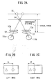
- Fig.2A shows the manner of observing a three-dimensional (stereoscopic) image where a sphere appears as jutting out, in which: denoted by numerals lla and 11b are the left and right eyes, respectively; 12 is a lens disposed immediately in front of the left and right eyes; and 13a and 13b are a left-eye LCD visual image display section and a right-eye LCD visual image display section, respectively, located adjacent to the lens 12, on which the visual images shown in Figs.2B and 2C are displayed, respectively.
- mark ⁇ represents an image at infinity and mark O represents a sphere which is displayed three-dimensionally (in a jutting out manner).
- XL represents the horizontal position of the sphere in the left-eye image
- XR represents the horizontal position of the sphere in the right-eye image, these being not equal to each other in value and shifted toward the right or toward the left from their median.
- Fig.2A what is denoted by numeral 15 is a virtual image position at which the sphere viewed by the left and right eyes is displayed, the eyes being focused on this position.
- Denoted by numeral 14 is a fusion image position at which the two images at the virtual image position 15 are viewed as one image by the two eyes.
- the distance from the position of lens 12 to the fusion image position 14 is referred to as a convergence distance and the distance from the position of lens 12 to the virtual image position 15 is referred to as a visual range.
- the parallax quantity represented by the difference in horizontal position between the left and right images (XL-XR), is in conformity with the convergence distance so that a larger parallax quantity means a greater jutting out toward the observer.
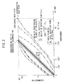
- the 45-degree solid line at the center represents the portion of complete correspondence between convergence and accommodation, the vicinity thereof indicating a range which is allowable for example due to depth of focus.
- the range somewhat varies depending on the adopted reference for allowance, i.e., visual acuity ( ⁇ :5 ⁇ ) or blur detectivity ( ⁇ :15 ⁇ ).
- the curves on the outer sides represent fusion image limit of the two eyes: the solid lines through black dots represent a maximum fusion image limit; the dotted lines represent the range in which a fusion image is established again from a condition of double images; and the dashed lines represent a fusion image limit when the image displaying time is 0.5 sec.
- a disclosure is made therein that a feeling of exhaustion is caused by a prolonged observation of a dynamic image unless it is a stereoscopic reproduction within the dashed-line range.
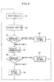
- a parallax "p" is detected from the left and right three-dimensional video signals (step S1).
- a function value for estimating the fatigue measure is then calculated based on the detected parallax "p" (step S2). This function calculation is performed by considering the influence (fatigue) produced on the observer's eye by a parallax in the stereoscopic image.
- a measure of such influence on the eye may be obtained from the diagram shown in Fig.3 , showing a correspondence between convergence (parallax) and accommodation (visual range) and their allowable range. It is indicated in Fig.3 that: the larger the difference between convergence (parallax) and accommodation (visual range) the greater the degree of influence (fatigue measure) produced on the eye.
- a function is formed as shown in the following equation (1) where an increase in ("visual range" - "parallax”) results in a nonlinear increase in the influence measure.
- ⁇ Influence measure ⁇ ⁇ ⁇ ⁇ Visual range ⁇ - ⁇ Parallax ⁇ 2 + ⁇ ⁇ ⁇ Visual range ⁇ - ⁇ Parallax ⁇ + ⁇
- the value of influence measure f(p) obtained by the above function calculation is compared with an allowable limit value "a" of convergence (fusion image) (for example the solid lines through the black dots in Fig.3 ) at which visual images may be recognized as a stereoscopic image (step S3).
- This allowable convergence limit value "a” may be regarded as an allowable fatigue limit value. If the value of influence measure f(p) obtained by the function calculation based on parallax is greater than the allowable convergence limit value "a”, the system is switched to display a two-dimensional image (step S4). If the value of influence measure f(p) is smaller than the allowable convergence limit value "a", a time accumulation of the value of influence measure f(p) is calculated (step S5).
- the accumulated calculation value of the influence measure value f(p) obtained by the function calculation based on parallax is then compared with an allowable accumulated convergence limit value "b" (step S6).
- This allowable accumulated convergence limit value "b” may be regarded as an allowable accumulated fatigue limit value and may be previously set by the maker of the apparatus, be individually adjusted and set by the user or be set by the user in accordance with the degree of fatigue when actually used. If the allowable accumulation convergence limit value "b” has been exceeded, the system is switched to display a two-dimensional image (step S7). If the allowable accumulation convergence limit value "b” has not been exceeded, the three-dimensional (stereoscopic) visual image is displayed as it is (step S8) and the above operation is executed in repetition.
- the system is automatically switched to a two-dimensional image when a three-dimensional image exceeding the fusion image limit has been received for a short time period, and it goes back to display a stereoscopic image upon returning of a visual image of a lesser influence measure. If, then, fatigue has been accumulated and exceeded the limit value as a result of observing three-dimensional image for a long time period, the system is automatically switched to a two-dimensional image and, thereafter, a two-dimensional image is to be observed.
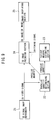
- the parallax quantity detecting section 2 is constituted by a correlation calculating section 2-1 at which a parallax signal "p" is obtained by performing a correlation calculation of the left and right video signals.
- the fatigue measure estimating section 3 includes a function calculating section 3-1 which receives the parallax signal "p" outputted from the parallax quantity detecting section 2 and provides a corresponding value of the function f(p) of influence measure (fatigue measure).
- An actual function calculation is not performed at the function calculating section 3-1, but it includes a table within a ROM so that, when a value of the parallax signal " p" has been inputted, a value of f(p) matching the corresponding influence measure (fatigue measure) is read out.
- the fatigue measure estimating section 3 further includes: a first comparison section 3-2 for receiving the value of function f(p) outputted from the function calculating section 3-1 and comparing it with the above described allowable convergence limit value "a"; and an accumulation calculating section 3-3 for also receiving the value of function f(p) outputted from the function calculating section 3-1 and calculating the time accumulation of such value f(p).
- the fatigue measure estimating section 3 furthermore includes a second comparison section 3-4 for comparing the accumulated value outputted from the accumulation calculating section 3-3 with the above described allowable accumulated convergence limit value "b".
- a signal for switching the stereoscopic image to a two-dimensional image is continuously transmitted when the accumulated value from the accumulation calculating section 3-3 has exceeded the allowable accumulated convergence limit value "b".
- Fig.6 is a block diagram showing the second embodiment, where like components as in the first embodiment shown in Fig.1 are denoted by like numerals.
- a parallax quantity changing section 6 is provided instead of the 3D/2D image switching section 4 in the first embodiment.
- a restrained stereoscopic video signal is provided with changing the parallax quantity (three-dimensionality) in stereoscopic video signal to a restrained parallax quantity, i.e., a target parallax quantity (restrained three-dimensionality) at which for example fatigue is not caused even after an uninterrupted observation, based on an output signal (parallax restraining signal) from a first comparison section, of the fatigue measure estimating section 3 of the same construction as that in the first embodiment shown in Fig.5 , where a value of function f(p) corresponding to parallax is compared with the allowable convergence limit value "a" and based on an output signal (parallax restraining signal) from a second comparison section where the accumulated calculation value of function f(p) corresponding to parallax is compared with the allowable accumulated convergence limit value "b".
- This target parallax quantity corresponds to the value at which accumulated fatigue due to an uninterrupted observation is allowable, i.e
- Figs.7A and 7B represent the left-eye image and right-eye image that are based on a stereoscopic video signal from the three-dimensional image reproducer.
- the parallax quantity (XL-XR) of these images the left-eye image shown in Fig.7A as a whole is shifted toward the left and the right-eye image shown in Fig.7B as a whole is shifted toward the right so as to change them as shown in Figs.7C and 7D .
- This shifting amount is the parallax restraining quantity.
- the parallax quantity (XL'-XR') becomes smaller so that a stereoscopic image is obtained as of the parallax quantity (three-dimensionality) at which fatigue is not caused even after an uninterrupted observation.
- shifting of the left and right images toward different directions from each other is shown as the technique for restraining parallax quantity.
- Other techniques for restraining the degree of three-dimensionality include a technique in which a compression of depth is effected.
- a relative depth of the object is inferred for example from the contrast in image and a three-dimensional visual image is generated by imparting a distortion to the image correspondingly to such depth.
- a stereoscopic image is generated by imparting a distortion [corresponding to parallax (XL-XR)] so that the position of the sphere is different between the left-eye image and the right-eye image as shown in Fig.8B .
- a visual image is generated as shown in Fig.8C in which the amount of distortion of the sphere is restrained. It is thereby possible to obtain a stereoscopic image of which the degree of three-dimensionality is restrained by compressing the depth thereof.
- the amount of distortion [parallax quantity (XL'-XR')] at this time is desirably a distortion amount within ⁇ 0.5 diopter (D) of visual range (accommodation) as also can be seen from the diagram of correspondence in Fig.3 .
- a further visual image system which does not form part of the present invention, will now be described.
- a three-dimensional image is generated by setting a parallax quantity (delay amount) according to the extent of motion in the two-dimensional image.
- the further visual image system is adapted to form a 2D/3D image switching signal at a fatigue measure estimating section on the basis of the parallax quantity set in such technique.
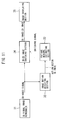
- Fig.9 is a block diagram showing the further visual image system, which does not form part of the present invention, including: 21, a two-dimensional image reproducer; 22, a parallax quantity determining section for determining the parallax quantity based on the extent of motion in the two-dimensional video signal from the two-dimensional image reproducer 21; and 23, a fatigue measure estimating section of the same construction as the fatigue measure estimating section in the first and second embodiments shown in Figs.1 and 6 , receiving a parallax quantity from the parallax quantity determining section 22 and transmitting a 2D/3D image switching signal.
- What is denoted by numeral 24 is a three-dimensional image generating section for receiving the parallax quantity set at the parallax quantity determining section 22 and transforming a two-dimensional image into a three-dimensional image
- 25 is a visual image display section for displaying a three-dimensional image from the three-dimensional image generating section 24 or a two-dimensional image.
- the parallax (XL-XR) between the three-dimensional left and right images as shown in Fig.10A is gradually reduced to those shown in Fig.10B and 10C .
- a third embodiment will now be described.
- motion vectors in the image are detected and the three-dimensional image is switched to a two-dimensional image on the basis of such motion vectors. It is generally said that a visual image involving a vigorous motion produces a greater influence on the observer.
- the present embodiment is made to eliminate an occurrence of such phenomenon.
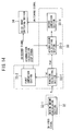
- Fig.11 is a block diagram showing the third embodiment, including: 31, a three-dimensional image reproducer; 32, an image motion detecting section for detecting motion vectors in a three-dimensional video signal outputted from the three-dimensional image reproducer 31; 33, a fatigue measure estimating section for estimating the degree of fatigue based on the motion vectors detected at the image motion detecting section 32; 34, a 3D/2D image switching section for providing an output by switching between three-dimensional video signal and two-dimensional video signal according to a switching signal which is provided on the basis of an estimation of fatigue measure; and 35, a visual image display section for displaying a three-dimensional image or a two-dimensional image provided from the image switching section 34.
- FIG.12A An example of detection of motion vector at the image motion detecting section 32 will now be described by way of Figs.12A to 12C .
- the background is being moved to the left as shown in Figs.12A and 12B .
- motion vectors as shown in Fig.12C are detected and, for example, an average of these values is inputted to the fatigue measure estimating section 33.
- a motion vector "m" is detected from a stereoscopic video signal (step S11).
- a function calculation for estimating the degree of fatigue is then performed on the basis of the detected motion vector "m” (step S12). This function calculation is performed by considering the influence (fatigue) produced on the eye of the observer by the image motion in the stereoscopic image.
- the value f(m) obtained by the above described function calculation is then compared with an allowable limit value "a" (step S13). If the value f(m) obtained by the function calculation based on the motion vectors is greater than the allowable limit value "a", the system is switched to display a two-dimensional image (step S14).
- step S15 a time accumulation is calculated of the function value f(m) (step S15).
- the calculated value of accumulation of value f(m) obtained by the function calculation based on the motion vectors is then compared with an allowable accumulation limit value "b" (step S16). If the calculated value of accumulation of the function calculation value f(m) has exceeded the allowable accumulation limit value "b”, the system is switched to display a two-dimensional image (step S17). If it is smaller than the allowable accumulation limit value "b", the three-dimensional (stereoscopic) image is displayed as it is (step S18) and the above operation is executed in repetition.
- the image motion detecting section 32 is constituted by a motion amount calculating section 32-1 for computing the motion vector "m" from a stereoscopic video signal.
- the fatigue measure estimating section 33 includes a function calculating section 33-1 for receiving motion vector "m” provided from the image motion detecting section 32 and outputting a corresponding function value f(m).
- an actual function calculation is not performed at the function calculating section 33-1, but it includes a table within a ROM so that, when a value of motion vector "m" has been inputted, a function value f(m) matching the corresponding influence measure (fatigue measure) is read out.
- the fatigue measure estimating section 33 further includes: a first comparison section 33-2 for receiving the value of function f(m) outputted from the function calculating section 33-1 and comparing it with the above described allowable limit value "a"; and an accumulation calculating section 33-3 for also receiving the value of function f(m) outputted from the function calculating section 33-1 and calculating the time accumulation of such value f(m).
- the fatigue measure estimating section 33 furthermore includes a second comparison section 33-4 for comparing the accumulated value outputted from the accumulation calculating section 33-3 with the above described allowable accumulated convergence limit value "b".
- a signal for continuously switching the stereoscopic image to a two-dimensional image is transmitted when the accumulated value from the accumulation calculating section 33-3 has exceeded the allowable accumulated convergence limit value "b".
- a parallax quantity (delay amount) is set in accordance with an extent of motion in a two-dimensional image in a similar manner to the system of Fig. 9 , and a 3D/2D image switching signal is formed at the fatigue measure estimating section by using the extent of motion in the two-dimensional image detected in generating a three-dimensional image.
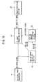
- Fig.15 is a block diagram showing the further visual image system, including: 41, a two-dimensional image reproducer; 42, a motion quantity detecting section for detecting motion vectors based on a two-dimensional video signal from the two-dimensional image reproducer 41; 43, a fatigue measure estimating section of the same construction as the fatigue measure estimating section 33 in the third embodiment shown in Fig.11 for receiving motion vectors from the motion amount detecting section 42 and transmitting a 3D/2D image switching signal.
- What is denoted by numeral 44 is a three-dimensional image generating section for receiving the motion vectors detected at the motion quantity detecting section 42 and transforming a two-dimensional image into a three-dimensional image
- 45 is a visual image display section for displaying the three-dimensional image from the three-dimensional image generating section 44 or a two-dimensional image.
- the degree of influence produced on the observer is estimated from inputted video signal and the three-dimensionality of stereoscopic image is restrained or a stereoscopic image is switched to a two-dimensional image on the basis of such influence measure estimating quantity, it is possible to achieve a visual image system in which a stereoscopic image can be suitably controlled so as not to produce such effects as fatigue on the observer without any biological measurement on the observer.
- the degree of influence produced on the observer is estimated from inputted video signal and display method of image is controlled on the basis of such influence measure estimating quantity, it is possible to achieve a visual image system in which the display method of image such as switching of stereoscopic image to two-dimensional image or restraining of parallax quantity can be suitably controlled so as not to produce such effects as fatigue on the observer also without any biological measurement on the observer.
Description
- The present invention relates to visual image systems and, more particularly, relates to a visual image system in which the degree of three-dimensionality is controlled by estimating effects produced on the observer based on video signals.
- Various proposals have been made with respect to visual image systems. For example, the following technique is disclosed in
Japanese Patent Publication No.2594235 - Further, the following technique is disclosed in
Japanese patent application laid open No.9-116928 - It is generally said that the eyes are more likely to become fatigued when observing a stereoscopic image comparing to the case of observing an ordinary two-dimensional image. As a proposal considering this point,
Japanese patent application laid open No.9-23451 - In the case of controlling the degree of three-dimensionality of stereoscopic image based on the degree of excitation and degree of fatigue of the user as in the method of the above-mentioned disclosure, however, the biological measurements on the user vary greatly from one individual to another, making it difficult to determine from the biological measurements a limit value of fatigue measure which is suitable to all the observers.
- Furthermore, there is another problem that it is troublesome to individually obtain the measurements from each observer.
- In
US-A-5726704 , binocular parallax of a captured image is detected and image pickup cameras are controlled so that their optic axes converge at an optimum point to ensure that the parallax of the captured image comes within the binocular fusing range of a viewer. Further, an optimum fixating point is calculated that enables the viewer to perceive the stereoscopic depth of the object over the widest possible range, and control is performed so that the fixating point is reproduced at a surface of a stereoscopic image display or at a designated distance from the surface. This suppresses the unnatural feel when the viewer views stereoscopic images. - In
JP-A-09-192349 - To eliminate the above problems in the known apparatus for controlling the degree of three-dimensionality of stereoscopic image, it is a main object of the present invention to provide a visual image system in which the degree of effects likely to be produced on the observer is inferred from inputted video signal without performing any biological measurement on the observer and it is thereby possible to suitably control a three-dimensionality measure of stereoscopic image.
- In accordance with a first aspect of the present invention, there is provided a visual image system comprising:
- fatigue measure estimating means arranged to estimate, from an inputted stereoscopic video signal, the degree of fatigue produced on an observer, as a fatigue of the eyes occurring due to the difference between parallax and visual range, based on a parallax quantity detected in images from said inputted stereoscopic video signal and to determine a degree of accumulated fatigue by calculating the time accumulation of said degree of fatigue; and
- three-dimensionality controlling means (4, 6) arranged, when said degree of accumulated fatigue exceeds a predetermined threshold ("b"), to reduce the parallax in said stereoscopic video signal, based on said degree of fatigue obtained at said fatigue measure estimating means (3), said parallax representing the degree of three-dimensionality of a stereoscopic image to be presented to the observer.
- In accordance with a second aspect of the present invention, there is provided a visual image system comprising:
- fatigue measure estimating means (33) arranged to estimate, from an inputted stereoscopic video signal, the degree of fatigue produced on an observer, as a fatigue of the eyes occurring due to a temporal motion, based on a motion vector detected in images from said inputted stereoscopic video signal, by
- detecting the temporal shift amount in said images, and to determine a degree of accumulated fatigue by calculating the time accumulation of said degree of fatigue; and
- three-dimensionality controlling means (34) arranged, when said degree of accumulated fatigue exceeds a predetermined threshold ("b"), to reduce the parallax in said stereoscopic video signal, based on said degree of fatigue obtained at said fatigue measure estimating means (33), said parallax representing the degree of three-dimensionality of a stereoscopic image to be presented to the observer.
- The degree of fatigue produced on the observer is thus estimated from inputted video signal and, on the basis of such fatigue measure estimating quantity, the degree of three-dimensionality of stereoscopic image is restrained or switching from stereoscopic image to two-dimensional image is regulated. It is thereby possible to achieve a visual image system in which stereoscopic image can be suitably controlled so as not to produce such effects as fatigue on the observer without any biological measurement on the observer. The above main object is thereby accomplished.
- Preferably, said three-dimensionality control means comprises means for regulating switching of stereoscopic image to be presented to the observer to two-dimensional image based on a fatigue measure estimating quantity obtained at the fatigue measure estimating means.
- Also disclosed herein, but not forming part of the present invention, is a visual image system including: fatigue measure estimating means for estimating from inputted video signal the degree of fatigue produced on an observer; and display controlling means for controlling displaying method of visual image to be presented to the observer based on a fatigue measure estimating quantity obtained at the fatigue measure estimating means.
- The degree of fatigue produced on the observer is thus estimated from inputted video signal and the displaying method of visual image is controlled on the basis of such fatigue measure estimating quantity. It is thereby possible to achieve a visual image system in which a suitable control on displaying method of visual image such as switching of stereoscopic image to two-dimensional image or restraining of parallax quantity for the purpose of not producing such effects as fatigue on the observer can be effected also without any biological measurement on the observer.
- The invention is described further hereinafter, by way of example only, with reference to the accompanying drawings, in which:-
-
Fig.1 is a schematic block diagram showing a first embodiment of the visual image system according to the present invention. -
Figs.2A, 2B, 2C are illustrations for explaining parallax quantity in a three-dimensional image. -
Fig.3 shows correspondence between convergence and accommodation and their allowable range explaining the relationship between parallax quantity and fatigue. -
Fig.4 is a flowchart for explaining an algorithm to be followed at the fatigue measure estimating section in the first embodiment shown inFig.1 . -
Fig.5 is a block diagram showing a construction of the fatigue estimating section in the first embodiment shown inFig.1 . -
Fig.6 is a block diagram showing a second embodiment of the present invention. -
Figs.7A, 7B, 7C, 7D illustrate an example of restraining the degree of three-dimensionality in a stereoscopic image. -
Figs.8A, 8B, 8C , 8D illustrate another example of restraining the degree of three-dimensionality in a stereoscopic image. -
Fig.9 is a block diagram showing a further visual image system, which does not form part of the present invention. -
Figs.10A, 10B, 10C, 10D show the manner of continuously varying parallax quantity in a stereoscopic image. -
Fig.11 is a block diagram showing a third embodiment of the present invention. -
Figs.12A, 12B, 12C illustrate an example of detecting motion vectors in visual image. -
Fig.13 is a flowchart for explaining an algorithm to be followed at the fatigue estimating section in the third embodiment shown inFig.11 . -
Fig.14 is a block diagram showing a construction of the fatigue estimating section in the third embodiment shown inFig.11 . -
Fig.15 is a block diagram showing a further visual image system, which does not form part of the present invention. - Some embodiments will now be described.
Fig.1 is a schematic block diagram showing a first embodiment of the visual image system according to the present invention. Referring toFig.1 : what is denoted bynumeral 1 is a three-dimensional image reproducer for transmitting three-dimensional video signal; 2, a parallax quantity detecting section for detecting a parallax quantity in three-dimensional video signal outputted from the three-dimensional image reproducer 1; 3, a fatigue measure estimating section for estimating a fatigue measure based on the parallax quantity detected at the parallaxquantity detecting section 2; 4, a 3D/2D image switching section for providing output by switching between three-dimensional video signal and two-dimensional video signal in accordance with an image switching signal which is provided on the basis of the estimation of fatigue measure; 5, an image display section for displaying a three-dimensional image or a two-dimensional image outputted by theimage switching section 4. It should be noted that, in the figure, 3D image represents a three-dimensional image and 2D image represents a two-dimensional image. - A description will now be given by way of
Figs.2A to 2C with respect to parallax quantity in a three-dimensional video signal.Fig.2A shows the manner of observing a three-dimensional (stereoscopic) image where a sphere appears as jutting out, in which: denoted by numerals lla and 11b are the left and right eyes, respectively; 12 is a lens disposed immediately in front of the left and right eyes; and 13a and 13b are a left-eye LCD visual image display section and a right-eye LCD visual image display section, respectively, located adjacent to thelens 12, on which the visual images shown inFigs.2B and 2C are displayed, respectively. Referring toFigs.2B, 2C , mark Δ represents an image at infinity and mark O represents a sphere which is displayed three-dimensionally (in a jutting out manner). Here, XL represents the horizontal position of the sphere in the left-eye image and XR represents the horizontal position of the sphere in the right-eye image, these being not equal to each other in value and shifted toward the right or toward the left from their median. - In
Fig.2A , what is denoted bynumeral 15 is a virtual image position at which the sphere viewed by the left and right eyes is displayed, the eyes being focused on this position. Denoted bynumeral 14 is a fusion image position at which the two images at thevirtual image position 15 are viewed as one image by the two eyes. Here, the distance from the position oflens 12 to thefusion image position 14 is referred to as a convergence distance and the distance from the position oflens 12 to thevirtual image position 15 is referred to as a visual range. The parallax quantity, represented by the difference in horizontal position between the left and right images (XL-XR), is in conformity with the convergence distance so that a larger parallax quantity means a greater jutting out toward the observer. - A description will now be given with respect to the relationship between the parallax quantity and the fatigue measure. A diagram as shown in
Fig.3 , indicating a correspondence between convergence and accommodation and their allowable range, and a disclosure of the following concept can be found in a Japanese journal "Seiri-kogaku" (Kabushikigaisha Shin-gijutsu Communications, Dec.1985: pp.103-105). The convergence along the axis of abscissa inFig.3 , corresponding to the convergence distance, is represented by convergence angle (MW) and the distance of its reciprocal. On the other hand, the accommodation along the axis of ordinate, corresponding to the visual range, is represented by diopter "D". Referring toFig.3 , the 45-degree solid line at the center represents the portion of complete correspondence between convergence and accommodation, the vicinity thereof indicating a range which is allowable for example due to depth of focus. The range somewhat varies depending on the adopted reference for allowance, i.e., visual acuity (ε :5µ) or blur detectivity (δ:15µ). The curves on the outer sides represent fusion image limit of the two eyes: the solid lines through black dots represent a maximum fusion image limit; the dotted lines represent the range in which a fusion image is established again from a condition of double images; and the dashed lines represent a fusion image limit when the image displaying time is 0.5 sec. A disclosure is made therein that a feeling of exhaustion is caused by a prolonged observation of a dynamic image unless it is a stereoscopic reproduction within the dashed-line range. - The present invention has been made based on these disclosures. A description will now be given by way of a flowchart in
Fig.4 with respect to an algorithm to be executed at the fatigue measure estimating section in the embodiment shown inFig.1 . First, a parallax "p" is detected from the left and right three-dimensional video signals (step S1). A function value for estimating the fatigue measure is then calculated based on the detected parallax "p" (step S2). This function calculation is performed by considering the influence (fatigue) produced on the observer's eye by a parallax in the stereoscopic image. For example, a measure of such influence on the eye may be obtained from the diagram shown inFig.3 , showing a correspondence between convergence (parallax) and accommodation (visual range) and their allowable range. It is indicated inFig.3 that: the larger the difference between convergence (parallax) and accommodation (visual range) the greater the degree of influence (fatigue measure) produced on the eye. As an example of the function f(p) for expressing the influence measure in such case, a function is formed as shown in the following equation (1) where an increase in ("visual range" - "parallax") results in a nonlinear increase in the influence measure.
- It is also known from the results of experiments conducted by the present inventors that: the larger the temporal change in parallax the greater the degree of influence on the eye. Accordingly, a function as shown in the following equation (2) may also be formed as an example of the function f(p) for expressing the influence measure.

- It should be noted that α, β, γ, in the above equations (1), (2) are coefficients and constants.
- Next, the value of influence measure f(p) obtained by the above function calculation is compared with an allowable limit value "a" of convergence (fusion image) (for example the solid lines through the black dots in
Fig.3 ) at which visual images may be recognized as a stereoscopic image (step S3). This allowable convergence limit value "a" may be regarded as an allowable fatigue limit value. If the value of influence measure f(p) obtained by the function calculation based on parallax is greater than the allowable convergence limit value "a", the system is switched to display a two-dimensional image (step S4). If the value of influence measure f(p) is smaller than the allowable convergence limit value "a", a time accumulation of the value of influence measure f(p) is calculated (step S5). The accumulated calculation value of the influence measure value f(p) obtained by the function calculation based on parallax is then compared with an allowable accumulated convergence limit value "b" (step S6). This allowable accumulated convergence limit value "b" may be regarded as an allowable accumulated fatigue limit value and may be previously set by the maker of the apparatus, be individually adjusted and set by the user or be set by the user in accordance with the degree of fatigue when actually used. If the allowable accumulation convergence limit value "b" has been exceeded, the system is switched to display a two-dimensional image (step S7). If the allowable accumulation convergence limit value "b" has not been exceeded, the three-dimensional (stereoscopic) visual image is displayed as it is (step S8) and the above operation is executed in repetition. - According to this algorithm, the system is automatically switched to a two-dimensional image when a three-dimensional image exceeding the fusion image limit has been received for a short time period, and it goes back to display a stereoscopic image upon returning of a visual image of a lesser influence measure. If, then, fatigue has been accumulated and exceeded the limit value as a result of observing three-dimensional image for a long time period, the system is automatically switched to a two-dimensional image and, thereafter, a two-dimensional image is to be observed.
- A description will now be given by way of a block diagram in
Fig.5 with respect to the construction of the parallax quantity detecting section and fatigue measure estimating section for executing the algorithm shown inFig.4 . The parallaxquantity detecting section 2 is constituted by a correlation calculating section 2-1 at which a parallax signal "p" is obtained by performing a correlation calculation of the left and right video signals. - The fatigue
measure estimating section 3 includes a function calculating section 3-1 which receives the parallax signal "p" outputted from the parallaxquantity detecting section 2 and provides a corresponding value of the function f(p) of influence measure (fatigue measure). An actual function calculation is not performed at the function calculating section 3-1, but it includes a table within a ROM so that, when a value of the parallax signal " p" has been inputted, a value of f(p) matching the corresponding influence measure (fatigue measure) is read out. - The fatigue
measure estimating section 3 further includes: a first comparison section 3-2 for receiving the value of function f(p) outputted from the function calculating section 3-1 and comparing it with the above described allowable convergence limit value "a"; and an accumulation calculating section 3-3 for also receiving the value of function f(p) outputted from the function calculating section 3-1 and calculating the time accumulation of such value f(p). If the value f(p) from the function calculating section 3-1 is greater than the allowable convergence limit value "a" at the above described first comparison section 3-2, a signal for temporarily switching the stereoscopic image to a two-dimensional image is provided to the 3D/2Dimage switching section 4 and at the same time a stop signal for temporarily stopping the accumulation calculation is transmitted to the above described accumulation calculating section 3-3. The fatiguemeasure estimating section 3 furthermore includes a second comparison section 3-4 for comparing the accumulated value outputted from the accumulation calculating section 3-3 with the above described allowable accumulated convergence limit value "b". A signal for switching the stereoscopic image to a two-dimensional image is continuously transmitted when the accumulated value from the accumulation calculating section 3-3 has exceeded the allowable accumulated convergence limit value "b". It should be noted that, since the value of allowable accumulated convergence limit value "b" to be used at the above described second comparison section 3-4 may be set by using various methods as previously described, means for setting the "b" values is provided correspondingly to such setting methods. - A second embodiment will now be described.
Fig.6 is a block diagram showing the second embodiment, where like components as in the first embodiment shown inFig.1 are denoted by like numerals. In this embodiment, a parallaxquantity changing section 6 is provided instead of the 3D/2Dimage switching section 4 in the first embodiment. It is constructed such that a restrained stereoscopic video signal is provided with changing the parallax quantity (three-dimensionality) in stereoscopic video signal to a restrained parallax quantity, i.e., a target parallax quantity (restrained three-dimensionality) at which for example fatigue is not caused even after an uninterrupted observation, based on an output signal (parallax restraining signal) from a first comparison section, of the fatiguemeasure estimating section 3 of the same construction as that in the first embodiment shown inFig.5 , where a value of function f(p) corresponding to parallax is compared with the allowable convergence limit value "a" and based on an output signal (parallax restraining signal) from a second comparison section where the accumulated calculation value of function f(p) corresponding to parallax is compared with the allowable accumulated convergence limit value "b". This target parallax quantity corresponds to the value at which accumulated fatigue due to an uninterrupted observation is allowable, i.e., an allowable accumulated fatigue value. - A description will now be given by way of
Figs.7A to 7D with respect to an example of conversion into a stereoscopic video signal at a restrained parallax quantity.Figs.7A and 7B represent the left-eye image and right-eye image that are based on a stereoscopic video signal from the three-dimensional image reproducer. In order to restrain the parallax quantity (XL-XR) of these images, the left-eye image shown inFig.7A as a whole is shifted toward the left and the right-eye image shown inFig.7B as a whole is shifted toward the right so as to change them as shown inFigs.7C and 7D . This shifting amount is the parallax restraining quantity. As a result of this operation, the parallax quantity (XL'-XR') becomes smaller so that a stereoscopic image is obtained as of the parallax quantity (three-dimensionality) at which fatigue is not caused even after an uninterrupted observation. - In the above embodiment, shifting of the left and right images toward different directions from each other is shown as the technique for restraining parallax quantity. Other techniques for restraining the degree of three-dimensionality include a technique in which a compression of depth is effected. Particularly, in the technique for transforming a two-dimensional image into a three-dimensional image as disclosed in
Japanese patent application laid-open No.9-116928 Fig.8A , a stereoscopic image is generated by imparting a distortion [corresponding to parallax (XL-XR)] so that the position of the sphere is different between the left-eye image and the right-eye image as shown inFig.8B . If the degree of three-dimensionality is to be restrained in such case, a visual image is generated as shown inFig.8C in which the amount of distortion of the sphere is restrained. It is thereby possible to obtain a stereoscopic image of which the degree of three-dimensionality is restrained by compressing the depth thereof. The amount of distortion [parallax quantity (XL'-XR')] at this time is desirably a distortion amount within ± 0.5 diopter (D) of visual range (accommodation) as also can be seen from the diagram of correspondence inFig.3 . - A further visual image system, which does not form part of the present invention, will now be described. In the technique for transforming a two-dimensional visual image into a three-dimensional visual image as disclosed in
Japanese Patent Publication No. 2594235 -
Fig.9 is a block diagram showing the further visual image system, which does not form part of the present invention, including: 21, a two-dimensional image reproducer; 22, a parallax quantity determining section for determining the parallax quantity based on the extent of motion in the two-dimensional video signal from the two-dimensional image reproducer 21; and 23, a fatigue measure estimating section of the same construction as the fatigue measure estimating section in the first and second embodiments shown inFigs.1 and6 , receiving a parallax quantity from the parallaxquantity determining section 22 and transmitting a 2D/3D image switching signal. What is denoted bynumeral 24 is a three-dimensional image generating section for receiving the parallax quantity set at the parallaxquantity determining section 22 and transforming a two-dimensional image into a three-dimensional image, and 25 is a visual image display section for displaying a three-dimensional image from the three-dimensionalimage generating section 24 or a two-dimensional image. - In the first embodiment shown in
Figs.1 and in the system ofFig. 9 , switching from a three-dimensional image to a two-dimensional image is made instantly with an interruption by a switching signal from the fatigue measure estimating section. If a three-dimensional image is thus switched in an instant to a two-dimensional image, however, a fusion image cannot be formed due to the large temporal change in parallax. A modification of the systems shown inFigs.1 and9 is thus described below by way ofFigs.10A to 10D , where the system is switched to a two-dimensional image while smoothly changing the degree of three-dimensionality, i.e., the parallax quantity is continuously changed. In this modification, the parallax (XL-XR) between the three-dimensional left and right images as shown inFig.10A is gradually reduced to those shown inFig.10B and 10C . A two-dimensional image is formed at the end by achieving XL=XR as shown inFig.10D . Switching of 3D/2D visual images is thereby possible without causing discomfort. - A third embodiment will now be described. In this embodiment, instead of parallax quantity in a three-dimensional image, motion vectors in the image are detected and the three-dimensional image is switched to a two-dimensional image on the basis of such motion vectors. It is generally said that a visual image involving a vigorous motion produces a greater influence on the observer. The present embodiment is made to eliminate an occurrence of such phenomenon.
Fig.11 is a block diagram showing the third embodiment, including: 31, a three-dimensional image reproducer; 32, an image motion detecting section for detecting motion vectors in a three-dimensional video signal outputted from the three-dimensional image reproducer 31; 33, a fatigue measure estimating section for estimating the degree of fatigue based on the motion vectors detected at the imagemotion detecting section 32; 34, a 3D/2D image switching section for providing an output by switching between three-dimensional video signal and two-dimensional video signal according to a switching signal which is provided on the basis of an estimation of fatigue measure; and 35, a visual image display section for displaying a three-dimensional image or a two-dimensional image provided from theimage switching section 34. - An example of detection of motion vector at the image
motion detecting section 32 will now be described by way ofFigs.12A to 12C . In this example of detection, the background is being moved to the left as shown inFigs.12A and 12B . Accordingly, motion vectors as shown inFig.12C are detected and, for example, an average of these values is inputted to the fatiguemeasure estimating section 33. - A description will now be given by way of the flowchart in
Fig.13 with respect to an algorithm to be executed at the fatiguemeasure estimating section 33 in this embodiment. First, a motion vector "m" is detected from a stereoscopic video signal (step S11). A function calculation for estimating the degree of fatigue is then performed on the basis of the detected motion vector "m" (step S12). This function calculation is performed by considering the influence (fatigue) produced on the eye of the observer by the image motion in the stereoscopic image. For example, a value of function f(m) is obtained on the basis of the extent and movement of the motion vector, the function being defined as that nonlinearly increasing in relation to the motion vector "m" such as in f(m) = α • m2 + β • m + γ. The value f(m) obtained by the above described function calculation is then compared with an allowable limit value "a" (step S13). If the value f(m) obtained by the function calculation based on the motion vectors is greater than the allowable limit value "a", the system is switched to display a two-dimensional image (step S14). If the value of function f(m) is smaller than the allowable limit value "a", a time accumulation is calculated of the function value f(m) (step S15). The calculated value of accumulation of value f(m) obtained by the function calculation based on the motion vectors is then compared with an allowable accumulation limit value "b" (step S16). If the calculated value of accumulation of the function calculation value f(m) has exceeded the allowable accumulation limit value "b", the system is switched to display a two-dimensional image (step S17). If it is smaller than the allowable accumulation limit value "b", the three-dimensional (stereoscopic) image is displayed as it is (step S18) and the above operation is executed in repetition. - A description will now be given by way of the block diagram of
Fig.14 with respect to the construction of the image motion detecting section and the fatigue measure estimating section for executing the algorithm shown inFig.13 . The imagemotion detecting section 32 is constituted by a motion amount calculating section 32-1 for computing the motion vector "m" from a stereoscopic video signal. The fatiguemeasure estimating section 33 includes a function calculating section 33-1 for receiving motion vector "m" provided from the imagemotion detecting section 32 and outputting a corresponding function value f(m). Similarly to the first embodiment, an actual function calculation is not performed at the function calculating section 33-1, but it includes a table within a ROM so that, when a value of motion vector "m" has been inputted, a function value f(m) matching the corresponding influence measure (fatigue measure) is read out. - The fatigue
measure estimating section 33 further includes: a first comparison section 33-2 for receiving the value of function f(m) outputted from the function calculating section 33-1 and comparing it with the above described allowable limit value "a"; and an accumulation calculating section 33-3 for also receiving the value of function f(m) outputted from the function calculating section 33-1 and calculating the time accumulation of such value f(m). If the value f(m) from the function calculating section 33-1 is greater than the allowable limit value "a" at the above described first comparison section 33-2, a signal for temporarily switching the stereoscopic image to a two-dimensional image is provided to the stereoscopic/2Dimage switching section 34 and at the same time a stop signal for temporarily stopping the accumulation calculation is transmitted to the above described accumulation calculating section 33-3. The fatiguemeasure estimating section 33 furthermore includes a second comparison section 33-4 for comparing the accumulated value outputted from the accumulation calculating section 33-3 with the above described allowable accumulated convergence limit value "b". A signal for continuously switching the stereoscopic image to a two-dimensional image is transmitted when the accumulated value from the accumulation calculating section 33-3 has exceeded the allowable accumulated convergence limit value "b". - A further visual image system, which does not form part of the present invention, will now be described. In this system, a parallax quantity (delay amount) is set in accordance with an extent of motion in a two-dimensional image in a similar manner to the system of
Fig. 9 , and a 3D/2D image switching signal is formed at the fatigue measure estimating section by using the extent of motion in the two-dimensional image detected in generating a three-dimensional image. -
Fig.15 is a block diagram showing the further visual image system, including: 41, a two-dimensional image reproducer; 42, a motion quantity detecting section for detecting motion vectors based on a two-dimensional video signal from the two-dimensional image reproducer 41; 43, a fatigue measure estimating section of the same construction as the fatiguemeasure estimating section 33 in the third embodiment shown inFig.11 for receiving motion vectors from the motionamount detecting section 42 and transmitting a 3D/2D image switching signal. What is denoted bynumeral 44 is a three-dimensional image generating section for receiving the motion vectors detected at the motionquantity detecting section 42 and transforming a two-dimensional image into a three-dimensional image, and 45 is a visual image display section for displaying the three-dimensional image from the three-dimensionalimage generating section 44 or a two-dimensional image. - In the above described third embodiment and the system of
Fig. 15 , too, it is furthermore possible to restrain the three-dimensionality of three-dimensional image by an output signal from the fatigue measure estimating section instead of the switching from three-dimensional image to two-dimensional image. Furthermore, it is also possible to cause a smooth change in parallax quantity as shown inFigs.7, 8 and10 . - As has been described by way of the above embodiments, since, in accordance with the invention, the degree of influence produced on the observer is estimated from inputted video signal and the three-dimensionality of stereoscopic image is restrained or a stereoscopic image is switched to a two-dimensional image on the basis of such influence measure estimating quantity, it is possible to achieve a visual image system in which a stereoscopic image can be suitably controlled so as not to produce such effects as fatigue on the observer without any biological measurement on the observer. Further, since, in accordance with the invention, the degree of influence produced on the observer is estimated from inputted video signal and display method of image is controlled on the basis of such influence measure estimating quantity, it is possible to achieve a visual image system in which the display method of image such as switching of stereoscopic image to two-dimensional image or restraining of parallax quantity can be suitably controlled so as not to produce such effects as fatigue on the observer also without any biological measurement on the observer.
Claims (5)
- A visual image system comprising:fatigue measure estimating means (3) arranged to estimate, from an inputted stereoscopic video signal, the degree of fatigue produced on an observer, as a fatigue of the eyes occurring due to the difference between parallax and visual range, based on a parallax quantity detected in images from said inputted stereoscopic video signal and to determine a degree of accumulated fatigue by calculating the time accumulation of said degree of fatigue; andthree-dimensionality controlling means (4, 6) arranged, when said degree of accumulated fatigue exceeds a predetermined threshold ("b"), to reduce the parallax in said stereoscopic video signal, based on said degree of fatigue obtained at said fatigue measure estimating means (3), said parallax representing the degree of three-dimensionality of a stereoscopic image to be presented to the observer.
- A visual image system comprising:fatigue measure estimating means (33) arranged to estimate, from an inputted stereoscopic video signal, the degree of fatigue produced on an observer, as a fatigue of the eyes occurring due to a temporal motion, based on a motion vector detected in images from said inputted stereoscopic video signal, by detecting the temporal shift amount in said images, and to determine a degree of accumulated fatigue by calculating the time accumulation of said degree of fatigue; andthree-dimensionality controlling means (34) arranged, when said degree of accumulated fatigue exceeds a predetermined threshold ("b"), to reduce the parallax in said stereoscopic video signal, based on said degree of fatigue obtained at said fatigue measure estimating means (33), said parallax representing the degree of three-dimensionality of a stereoscopic image to be presented to the observer.
- A visual image system according to claim 1 or claim 2, wherein said three-dimensionality controlling means (4, 6, 34) comprises means (4, 34) for regulating switching of a stereoscopic image to be presented to an observer to a two-dimensional image based on a degree of fatigue obtained at the fatigue measure estimating means (3).
- A visual image system according to claim 3, wherein said means (4, 34) for regulating switching of images regulates switching from a stereoscopic image to a two-dimensional image while changing the parallax of the stereoscopic image smoothly without an interruption.
- A visual image system according to any of claims 1 to 4, wherein said fatigue measure estimating means (3) estimates the time accumulation of the degree of fatigue produced on the observer by a time integral thereof.
Applications Claiming Priority (2)
| Application Number | Priority Date | Filing Date | Title |
|---|---|---|---|
| JP17053198A JP4149037B2 (en) | 1998-06-04 | 1998-06-04 | Video system |
| JP17053198 | 1998-06-04 |
Publications (3)
| Publication Number | Publication Date |
|---|---|
| EP0963122A2 EP0963122A2 (en) | 1999-12-08 |
| EP0963122A3 EP0963122A3 (en) | 2002-06-26 |
| EP0963122B1 true EP0963122B1 (en) | 2010-12-15 |
Family
ID=15906660
Family Applications (1)
| Application Number | Title | Priority Date | Filing Date |
|---|---|---|---|
| EP99303904A Expired - Lifetime EP0963122B1 (en) | 1998-06-04 | 1999-05-19 | Stereoscopic imaging system |
Country Status (4)
| Country | Link |
|---|---|
| US (2) | US6614927B1 (en) |
| EP (1) | EP0963122B1 (en) |
| JP (1) | JP4149037B2 (en) |
| DE (1) | DE69943034D1 (en) |
Families Citing this family (136)
| Publication number | Priority date | Publication date | Assignee | Title |
|---|---|---|---|---|
| JP2003018619A (en) | 2001-07-03 | 2003-01-17 | Olympus Optical Co Ltd | Three-dimensional image evaluation apparatus and display using the same |
| GB0129992D0 (en) * | 2001-12-14 | 2002-02-06 | Ocuity Ltd | Control of optical switching apparatus |
| JP3673217B2 (en) | 2001-12-20 | 2005-07-20 | オリンパス株式会社 | Video display device |
| AU2003252388A1 (en) * | 2002-08-27 | 2004-03-19 | Sharp Kabushiki Kaisha | Content reproduction device capable of reproducing a content in optimal reproduction mode |
| EP1403759A3 (en) * | 2002-09-17 | 2007-04-04 | Sharp Kabushiki Kaisha | Electronic equipment with two and three dimensional display functions |
| JP2004165709A (en) * | 2002-09-27 | 2004-06-10 | Sharp Corp | Stereoscopic image display apparatus, stereoscopic image recording method, and stereoscopic image transmission method |
| ES2392244T3 (en) | 2002-09-27 | 2012-12-07 | Sharp Kabushiki Kaisha | 3D image display device |
| CN1703915A (en) * | 2002-09-27 | 2005-11-30 | 夏普株式会社 | 3-D image display unit, 3-D image recording device and 3-D image recording method |
| JP2004165710A (en) * | 2002-09-27 | 2004-06-10 | Sharp Corp | Stereoscopic image display apparatus, stereoscopic image recording method, and stereoscopic image transmission method |
| JP4713054B2 (en) * | 2002-09-27 | 2011-06-29 | シャープ株式会社 | Stereo image display device, stereo image encoding device, stereo image decoding device, stereo image recording method, and stereo image transmission method |
| JP4145122B2 (en) * | 2002-09-27 | 2008-09-03 | シャープ株式会社 | Stereoscopic image display device |
| BRPI0306684B1 (en) | 2002-11-01 | 2018-03-13 | Godo Kaisha Ip Bridge 1 | "Image signal coding method and apparatus and image signal decoding method and apparatus" |
| JP2004246725A (en) * | 2003-02-14 | 2004-09-02 | Sharp Corp | Display device, display control device, display control program, and computer-readable recording medium recording the same |
| JP4490074B2 (en) | 2003-04-17 | 2010-06-23 | ソニー株式会社 | Stereoscopic image processing apparatus, stereoscopic image display apparatus, stereoscopic image providing method, and stereoscopic image processing system |
| US20040222987A1 (en) * | 2003-05-08 | 2004-11-11 | Chang Nelson Liang An | Multiframe image processing |
| WO2004107765A1 (en) * | 2003-05-28 | 2004-12-09 | Sanyo Electric Co., Ltd. | 3-dimensional video display device, text data processing device, program, and storage medium |
| JP2004357156A (en) * | 2003-05-30 | 2004-12-16 | Sharp Corp | Video reception apparatus and video playback apparatus |
| US7411611B2 (en) * | 2003-08-25 | 2008-08-12 | Barco N. V. | Device and method for performing multiple view imaging by means of a plurality of video processing devices |
| EP1727093A1 (en) * | 2003-12-19 | 2006-11-29 | Tdvision Corporation S.A. DE C.V. | 3d videogame system |
| JP4665430B2 (en) * | 2004-04-26 | 2011-04-06 | 富士ゼロックス株式会社 | Image output control device, image output control method, image output control program, and printer device |
| WO2006016315A1 (en) | 2004-08-10 | 2006-02-16 | Koninklijke Philips Electronics N.V. | Detection of view mode |
| WO2006019039A1 (en) * | 2004-08-18 | 2006-02-23 | Sharp Kabushiki Kaisha | Image data display |
| KR100861476B1 (en) * | 2004-08-18 | 2008-10-02 | 샤프 가부시키가이샤 | Image data display apparatus |
| JP4602737B2 (en) * | 2004-10-25 | 2010-12-22 | シャープ株式会社 | Video display device |
| JP4246691B2 (en) * | 2004-11-30 | 2009-04-02 | 本田技研工業株式会社 | Image information processing system, image information processing method, image information processing program, and automobile |
| US20060139448A1 (en) * | 2004-12-29 | 2006-06-29 | Samsung Electronics Co., Ltd. | 3D displays with flexible switching capability of 2D/3D viewing modes |
| JP4046121B2 (en) * | 2005-03-24 | 2008-02-13 | セイコーエプソン株式会社 | Stereoscopic image display apparatus and method |
| JP4555722B2 (en) * | 2005-04-13 | 2010-10-06 | 株式会社 日立ディスプレイズ | 3D image generator |
| KR100932977B1 (en) | 2005-07-05 | 2009-12-21 | 삼성모바일디스플레이주식회사 | Stereoscopic video display |
| KR100913173B1 (en) | 2005-07-05 | 2009-08-19 | 삼성모바일디스플레이주식회사 | 3 dimension graphic processor and autostereoscopic display device using the same |
| US8885017B2 (en) * | 2005-07-14 | 2014-11-11 | 3Ality Digital Systems, Llc | Real-time process and technology using image processing to maintain and ensure viewer comfort during capture, live transmission, and post-production of stereoscopic 3D imagery |
| US8279221B2 (en) | 2005-08-05 | 2012-10-02 | Samsung Display Co., Ltd. | 3D graphics processor and autostereoscopic display device using the same |
| KR100739730B1 (en) * | 2005-09-03 | 2007-07-13 | 삼성전자주식회사 | Apparatus and method for processing 3D dimensional picture |
| KR100739764B1 (en) | 2005-11-28 | 2007-07-13 | 삼성전자주식회사 | Apparatus and method for processing 3 dimensional video signal |
| JP5059024B2 (en) * | 2005-12-19 | 2012-10-24 | コーニンクレッカ フィリップス エレクトロニクス エヌ ヴィ | 3D image display method and apparatus |
| KR101102004B1 (en) * | 2005-12-30 | 2012-01-04 | 삼성전자주식회사 | A method and system for quantitating fatigue resulting from a three dimensional display |
| US8350780B1 (en) * | 2006-03-29 | 2013-01-08 | Nvidia Corporation | System, method and computer program product for controlling stereoscopic glasses |
| KR100893616B1 (en) * | 2006-04-17 | 2009-04-20 | 삼성모바일디스플레이주식회사 | Electronic imaging device, 2d/3d image display device and the driving method thereof |
| TWI331872B (en) * | 2006-12-29 | 2010-10-11 | Quanta Comp Inc | Method for displaying stereoscopic image |
| KR101313740B1 (en) * | 2007-10-08 | 2013-10-15 | 주식회사 스테레오피아 | OSMU( One Source Multi Use)-type Stereoscopic Camera and Method of Making Stereoscopic Video Content thereof |
| WO2009075495A1 (en) * | 2007-12-10 | 2009-06-18 | Samsung Electronics Co., Ltd. | System and method for generating and reproducing image file including 2d image and 3d stereoscopic image |
| BRPI0820739B1 (en) * | 2007-12-14 | 2020-10-20 | Koninklijke Philips N.V. | method of reproducing video information, reproduction device for reproducing video information, signal, and, recording carrier |
| CA2723627C (en) | 2008-05-12 | 2017-01-24 | Dong-Qing Zhang | System and method for measuring potential eyestrain of stereoscopic motion pictures |
| KR100991804B1 (en) * | 2008-06-10 | 2010-11-04 | 유한회사 마스터이미지쓰리디아시아 | Stereoscopic Image Generation Chip For Mobile Equipment, and Method For Generating Stereoscopic Image Using The Same |
| KR101539935B1 (en) * | 2008-06-24 | 2015-07-28 | 삼성전자주식회사 | Method and apparatus for processing 3D video image |
| WO2010049868A1 (en) * | 2008-10-28 | 2010-05-06 | Koninklijke Philips Electronics N.V. | A three dimensional display system |
| WO2010061689A1 (en) | 2008-11-26 | 2010-06-03 | 日本電気株式会社 | Display device, terminal device, and display method |
| PL2362672T3 (en) * | 2008-12-01 | 2016-10-31 | Contents reproduction device, reproduction method, program and recording medium | |
| US9285599B2 (en) | 2009-01-22 | 2016-03-15 | Nec Corporation | Three-dimensional video viewing system, display system, optical shutter, and three-dimensional video viewing method |
| JP5409107B2 (en) * | 2009-05-13 | 2014-02-05 | 任天堂株式会社 | Display control program, information processing apparatus, display control method, and information processing system |
| EP2434763A4 (en) * | 2009-05-18 | 2014-02-26 | Lg Electronics Inc | 3d image reproduction device and method capable of selecting 3d mode for 3d image |
| JP4609805B2 (en) * | 2009-05-28 | 2011-01-12 | Necカシオモバイルコミュニケーションズ株式会社 | Terminal device and program |
| JP5257248B2 (en) | 2009-06-03 | 2013-08-07 | ソニー株式会社 | Image processing apparatus and method, and image display apparatus |
| JP2011101229A (en) * | 2009-11-06 | 2011-05-19 | Sony Corp | Display control device, display control method, program, output device, and transmission apparatus |
| JP4587237B1 (en) * | 2009-06-17 | 2010-11-24 | Necカシオモバイルコミュニケーションズ株式会社 | Terminal device and program |
| JP5249149B2 (en) | 2009-07-17 | 2013-07-31 | 富士フイルム株式会社 | Stereoscopic image recording apparatus and method, stereoscopic image output apparatus and method, and stereoscopic image recording and output system |
| US9924154B2 (en) | 2009-07-27 | 2018-03-20 | Koninklijke Philips N.V. | Switching between 3D video and 2D video |
| JP2011035592A (en) * | 2009-07-31 | 2011-02-17 | Nintendo Co Ltd | Display control program and information processing system |
| WO2011024373A1 (en) * | 2009-08-31 | 2011-03-03 | パナソニック株式会社 | Stereoscopic vision control device, integrated circuit, stereoscopic vision control method |
| JP2011064894A (en) * | 2009-09-16 | 2011-03-31 | Fujifilm Corp | Stereoscopic image display apparatus |
| US8284235B2 (en) * | 2009-09-28 | 2012-10-09 | Sharp Laboratories Of America, Inc. | Reduction of viewer discomfort for stereoscopic images |
| JP5405264B2 (en) * | 2009-10-20 | 2014-02-05 | 任天堂株式会社 | Display control program, library program, information processing system, and display control method |
| JP4754031B2 (en) * | 2009-11-04 | 2011-08-24 | 任天堂株式会社 | Display control program, information processing system, and program used for stereoscopic display control |
| JP2011101230A (en) * | 2009-11-06 | 2011-05-19 | Sony Corp | Display control device, display control method, program, output device, and transmission apparatus |
| JP5449079B2 (en) * | 2009-12-11 | 2014-03-19 | 三菱電機株式会社 | Stereoscopic video viewing restriction device and method, stereoscopic video viewing restriction notification device and method, video viewing device and method, and video viewing system |
| WO2011080878A1 (en) * | 2009-12-28 | 2011-07-07 | パナソニック株式会社 | Image playback device and display device |
| EP2355526A3 (en) | 2010-01-14 | 2012-10-31 | Nintendo Co., Ltd. | Computer-readable storage medium having stored therein display control program, display control apparatus, display control system, and display control method |
| JP5505881B2 (en) * | 2010-02-02 | 2014-05-28 | 学校法人早稲田大学 | Stereoscopic image production apparatus and program |
| GB2478157A (en) * | 2010-02-26 | 2011-08-31 | Sony Corp | Method and apparatus for cutting between a first and second image sequence in a stereoscopic video |
| GB2478164A (en) | 2010-02-26 | 2011-08-31 | Sony Corp | Calculating misalignment between a stereoscopic image pair based on feature positions |
| JP5533092B2 (en) * | 2010-03-18 | 2014-06-25 | 株式会社リコー | Method for identifying data point distribution region on coordinate plane and identification program thereof |
| JP5454396B2 (en) * | 2010-03-23 | 2014-03-26 | 株式会社Jvcケンウッド | Stereo image generation device, stereo image generation method, information transmission device, and information transmission method |
| WO2011121818A1 (en) * | 2010-03-30 | 2011-10-06 | 富士フイルム株式会社 | Compound-eye imaging device, and disparity adjustment method and program therefor |
| JP2011216964A (en) * | 2010-03-31 | 2011-10-27 | Sony Corp | Display control unit, display control method and program |
| WO2011125368A1 (en) * | 2010-04-05 | 2011-10-13 | シャープ株式会社 | Three-dimensional image display device, display system, drive method, drive device, display control method, display control device, program, and computer-readable recording medium |
| KR101682205B1 (en) * | 2010-05-03 | 2016-12-05 | 삼성전자주식회사 | Apparatus and method of reducing visual fatigue of 3-dimension image |
| US9693039B2 (en) | 2010-05-27 | 2017-06-27 | Nintendo Co., Ltd. | Hand-held electronic device |
| US8970672B2 (en) | 2010-05-28 | 2015-03-03 | Qualcomm Incorporated | Three-dimensional image processing |
| KR101753801B1 (en) * | 2010-06-10 | 2017-07-04 | 엘지디스플레이 주식회사 | Liquid crystal display device and driving method for thereof |
| JP5186715B2 (en) | 2010-06-14 | 2013-04-24 | 任天堂株式会社 | Display control program, display control device, display control method, and display control system |
| JP5420076B2 (en) | 2010-06-30 | 2014-02-19 | 富士フイルム株式会社 | Reproduction apparatus, compound eye imaging apparatus, reproduction method, and program |
| CN102972032A (en) * | 2010-06-30 | 2013-03-13 | 富士胶片株式会社 | Three-dimensional image display device, three-dimensional image display method, three-dimensional image display program, and recording medium |
| JP2012029216A (en) * | 2010-07-27 | 2012-02-09 | Sony Corp | Reproduction device, reproduction method, and program |
| KR101150871B1 (en) * | 2010-07-29 | 2012-06-13 | 연세대학교 산학협력단 | Method and apparatus for calculating fatigue of stereoscopic image based on horizontal disparity and vertical disparity |
| TWI436636B (en) * | 2010-08-16 | 2014-05-01 | Acer Inc | Method and apparatus for adjusting three dimension video image |
| JP5025772B2 (en) * | 2010-08-30 | 2012-09-12 | 株式会社東芝 | Stereoscopic glasses and stereoscopic video display system |
| JP5140210B2 (en) | 2010-08-31 | 2013-02-06 | パナソニック株式会社 | Imaging apparatus and image processing method |
| JP5204349B2 (en) * | 2010-08-31 | 2013-06-05 | パナソニック株式会社 | Imaging apparatus, playback apparatus, and image processing method |
| US8704879B1 (en) | 2010-08-31 | 2014-04-22 | Nintendo Co., Ltd. | Eye tracking enabling 3D viewing on conventional 2D display |
| KR20120056929A (en) * | 2010-09-20 | 2012-06-05 | 엘지전자 주식회사 | Mobile terminal and operation control method thereof |
| CN103392343B (en) * | 2010-09-20 | 2016-03-09 | 联发科技(新加坡)私人有限公司 | Display unit, display packing and Play System |
| JP5530322B2 (en) * | 2010-09-22 | 2014-06-25 | オリンパスイメージング株式会社 | Display device and display method |
| JP5263355B2 (en) * | 2010-09-22 | 2013-08-14 | 株式会社ニコン | Image display device and imaging device |
| JP5543892B2 (en) * | 2010-10-01 | 2014-07-09 | 日立コンシューマエレクトロニクス株式会社 | REPRODUCTION DEVICE, REPRODUCTION METHOD, DISPLAY DEVICE, AND DISPLAY METHOD |
| KR101633336B1 (en) * | 2010-10-01 | 2016-06-24 | 엘지전자 주식회사 | Mobile terminal and method for controlling thereof |
| KR101309705B1 (en) * | 2010-10-21 | 2013-09-17 | 도시바삼성스토리지테크놀러지코리아 주식회사 | Glasses and 3D image display system employing the same |
| KR101682208B1 (en) * | 2010-10-22 | 2016-12-02 | 삼성전자주식회사 | Display apparatus and method |
| US20120113235A1 (en) * | 2010-11-08 | 2012-05-10 | Sony Corporation | 3d glasses, systems, and methods for optimized viewing of 3d video content |
| JP2012103980A (en) * | 2010-11-11 | 2012-05-31 | Sony Corp | Image processing device, image processing method, and program |
| KR101732041B1 (en) | 2010-11-19 | 2017-05-04 | 삼성디스플레이 주식회사 | Three dimensional image display device |
| KR101587623B1 (en) | 2010-12-09 | 2016-01-21 | 한국전자통신연구원 | A System for Making 3D Contents Provided with Visual Fatigue Minimization and Method of The same |
| KR101220223B1 (en) | 2010-12-13 | 2013-01-09 | 한국전자통신연구원 | Method and apparatus for visual discomfort metric of stereoscopic video, recordable medium which program for executing method is recorded |
| JP2012151663A (en) * | 2011-01-19 | 2012-08-09 | Toshiba Corp | Stereophonic sound generation device and stereophonic sound generation method |
| JP5417356B2 (en) * | 2011-02-08 | 2014-02-12 | 株式会社東芝 | Video processing device, video processing method, and stereoscopic video display device |
| JP2012170503A (en) * | 2011-02-17 | 2012-09-10 | Kyoraku Sangyo Kk | Game machine |
| JP5351915B2 (en) * | 2011-02-24 | 2013-11-27 | 富士フイルム株式会社 | 3D image processing apparatus, method, and program |
| JP5664356B2 (en) * | 2011-03-09 | 2015-02-04 | 富士通株式会社 | Generation apparatus and generation method |
| US8654181B2 (en) | 2011-03-28 | 2014-02-18 | Avid Technology, Inc. | Methods for detecting, visualizing, and correcting the perceived depth of a multicamera image sequence |
| WO2012133286A1 (en) | 2011-03-31 | 2012-10-04 | 株式会社Jvcケンウッド | Three-dimensional image generating apparatus and three-dimensional image generating method |
| JP5871113B2 (en) * | 2011-03-31 | 2016-03-01 | 株式会社Jvcケンウッド | Stereo image generation apparatus, stereo image generation method, and stereo image generation program |
| JP5052683B1 (en) * | 2011-04-19 | 2012-10-17 | 株式会社東芝 | Electronic device and video display method |
| CN102918861A (en) * | 2011-04-28 | 2013-02-06 | 松下电器产业株式会社 | Stereoscopic intensity adjustment device, stereoscopic intensity adjustment method, program, integrated circuit, and recording medium |
| KR101218723B1 (en) * | 2011-05-09 | 2013-01-09 | 성균관대학교산학협력단 | Method for providing three-dimensional image considering visual fatigue of user |
| GB2546641B (en) * | 2011-05-13 | 2017-12-27 | Snell Advanced Media Ltd | Video processing method and apparatus for use with a sequence of stereoscopic images |
| TR201104918A2 (en) | 2011-05-20 | 2012-12-21 | Vestel Elektroni̇k Sanayi̇ Ve Ti̇caret A.Ş. | Method and device for creating depth map and 3D video. |
| US9420259B2 (en) | 2011-05-24 | 2016-08-16 | Comcast Cable Communications, Llc | Dynamic distribution of three-dimensional content |
| WO2012170984A1 (en) * | 2011-06-09 | 2012-12-13 | Cstereo3D, Llc | Device and method for rendering and delivering 3-d content |
| KR101779423B1 (en) * | 2011-06-10 | 2017-10-10 | 엘지전자 주식회사 | Method and apparatus for processing image |
| US8879826B2 (en) * | 2011-07-05 | 2014-11-04 | Texas Instruments Incorporated | Method, system and computer program product for switching between 2D and 3D coding of a video sequence of images |
| US9402065B2 (en) | 2011-09-29 | 2016-07-26 | Qualcomm Incorporated | Methods and apparatus for conditional display of a stereoscopic image pair |
| EP2764695A1 (en) * | 2011-10-04 | 2014-08-13 | Telefonaktiebolaget LM Ericsson (PUBL) | Objective 3d video quality assessment model |
| KR20130054176A (en) * | 2011-11-14 | 2013-05-24 | 삼성전자주식회사 | Method and apparatus for measuring asthenopia of three dimentional image |
| US9191659B2 (en) * | 2011-11-16 | 2015-11-17 | Christie Digital Systems Usa, Inc. | Collimated stereo display system |
| WO2013081235A1 (en) * | 2011-11-28 | 2013-06-06 | 한국과학기술원 | Apparatus for visualizing visual fatigue in 3d stereoscopic image |
| KR102131745B1 (en) * | 2012-01-04 | 2020-07-08 | 인터디지탈 매디슨 페이튼트 홀딩스 | Processing 3d image sequences |
| US20150062313A1 (en) * | 2012-03-30 | 2015-03-05 | Sony Corporation | Display control device, display control method, and program |
| WO2013145326A1 (en) | 2012-03-30 | 2013-10-03 | 富士通株式会社 | Determination device, determination program, and determination method |
| US9300942B2 (en) | 2012-10-18 | 2016-03-29 | Industrial Technology Research Institute | Method and control system for three-dimensional video playback using visual fatigue estimation |
| CN103780894B (en) * | 2012-10-18 | 2016-02-10 | 财团法人工业技术研究院 | The anaglyph player method of tool visual fatigue estimation and control system |
| KR102153606B1 (en) | 2013-08-13 | 2020-09-08 | 삼성전자주식회사 | Apparatus and method for estimating user fatigue degree of video content |
| CN109730708B (en) * | 2013-10-24 | 2022-10-18 | 佳能株式会社 | Information processing apparatus, information processing method, and control apparatus |
| KR101521213B1 (en) * | 2014-06-25 | 2015-05-18 | 연세대학교 산학협력단 | Apparatus for correcting stereoscopic image using visual discomfort model and method thereof |
| JP2016115965A (en) * | 2014-12-11 | 2016-06-23 | ソニー株式会社 | Medical spectacle type display device, information processing device, and information processing method |
| CN109716761B (en) * | 2016-09-23 | 2020-12-08 | 日本电信电话株式会社 | Image generation device, image generation method, and recording medium |
| CN108881877B (en) * | 2017-05-12 | 2020-07-24 | 京东方科技集团股份有限公司 | Display processing device, display processing method thereof and display device |
| WO2019215984A1 (en) * | 2018-05-09 | 2019-11-14 | オリンパス株式会社 | Image processing device and image generation method |
Family Cites Families (17)
| Publication number | Priority date | Publication date | Assignee | Title |
|---|---|---|---|---|
| JPS62293381A (en) * | 1986-06-11 | 1987-12-19 | Toshiba Corp | Stereoscopic picture display device |
| DE69417824D1 (en) * | 1993-08-26 | 1999-05-20 | Matsushita Electric Ind Co Ltd | Stereoscopic scanner |
| JP2594235B2 (en) | 1994-02-01 | 1997-03-26 | 三洋電機株式会社 | Method for converting 2D image to 3D image and 3D image signal generation device |
| WO1996027992A2 (en) * | 1995-03-08 | 1996-09-12 | Philips Electronics N.V. | Three-dimensional image display system |
| JPH0918894A (en) * | 1995-06-26 | 1997-01-17 | Sanyo Electric Co Ltd | Stereoscopic image display device |
| US6005607A (en) * | 1995-06-29 | 1999-12-21 | Matsushita Electric Industrial Co., Ltd. | Stereoscopic computer graphics image generating apparatus and stereoscopic TV apparatus |
| JPH0923451A (en) * | 1995-07-05 | 1997-01-21 | Sanyo Electric Co Ltd | Sensitivity response controller |
| JP3525970B2 (en) * | 1996-01-19 | 2004-05-10 | 株式会社タイトー | A parallax adjustment device for a game machine that can experience stereoscopic viewing |
| US6061179A (en) * | 1996-01-23 | 2000-05-09 | Canon Kabushiki Kaisha | Stereoscopic image display apparatus with two-/three-dimensional image display switching function |
| JPH09322199A (en) * | 1996-05-29 | 1997-12-12 | Olympus Optical Co Ltd | Stereoscopic video display device |
| DE69730565T2 (en) * | 1996-06-26 | 2005-02-03 | Matsushita Electric Industrial Co., Ltd., Kadoma | Apparatus for generating a stereoscopic moving image by means of computer graphics |
| DE69706611T2 (en) * | 1996-06-27 | 2002-07-04 | Toshiba Kawasaki Kk | Stereoscopic display system and method |
| US6023277A (en) * | 1996-07-03 | 2000-02-08 | Canon Kabushiki Kaisha | Display control apparatus and method |
| JP3397602B2 (en) * | 1996-11-11 | 2003-04-21 | 富士通株式会社 | Image display apparatus and method |
| US5771066A (en) * | 1997-01-03 | 1998-06-23 | Barnea; Daniel I. | Three dimensional display device |
| US6278480B1 (en) * | 1997-02-07 | 2001-08-21 | Canon Kabushiki Kaisha | Compound eye camera system |
| JPH10224825A (en) * | 1997-02-10 | 1998-08-21 | Canon Inc | Image display system, image display device in the system, information processing unit, control method and storage medium |
-
1998
- 1998-06-04 JP JP17053198A patent/JP4149037B2/en not_active Expired - Fee Related
-
1999
- 1999-05-19 DE DE69943034T patent/DE69943034D1/en not_active Expired - Lifetime
- 1999-05-19 EP EP99303904A patent/EP0963122B1/en not_active Expired - Lifetime
- 1999-06-02 US US09/323,694 patent/US6614927B1/en not_active Expired - Lifetime
-
2003
- 2003-07-03 US US10/611,963 patent/US6996267B2/en not_active Expired - Fee Related
Also Published As
| Publication number | Publication date |
|---|---|
| JP4149037B2 (en) | 2008-09-10 |
| JPH11355808A (en) | 1999-12-24 |
| EP0963122A2 (en) | 1999-12-08 |
| US20040057612A1 (en) | 2004-03-25 |
| US6996267B2 (en) | 2006-02-07 |
| EP0963122A3 (en) | 2002-06-26 |
| DE69943034D1 (en) | 2011-01-27 |
| US6614927B1 (en) | 2003-09-02 |
Similar Documents
| Publication | Publication Date | Title |
|---|---|---|
| EP0963122B1 (en) | Stereoscopic imaging system | |
| US6198484B1 (en) | Stereoscopic display system | |
| US6864910B1 (en) | Optical apparatus | |
| US5726704A (en) | Stereoscopic image pickup and display apparatus | |
| EP2299728B1 (en) | Stereoscopic image display apparatus | |
| US6175379B1 (en) | Stereoscopic CG image generating apparatus and stereoscopic TV apparatus | |
| CN108663799A (en) | A kind of display control program and its display control method of VR images | |
| US20040066555A1 (en) | Method and apparatus for generating stereoscopic images | |
| EP0707287B1 (en) | Image processing apparatus and method | |
| JPH03292093A (en) | Three-dimensional display device | |
| JP2008524673A (en) | Stereo camera image distortion correction apparatus and method | |
| WO2012124150A1 (en) | Video display device | |
| Wang et al. | Perceptual quality of asymmetrically distorted stereoscopic images: the role of image distortion types | |
| JP2006208407A (en) | Microscopic system for observing stereoscopic picture | |
| CN102006494A (en) | Method and device for adjusting three-dimensional (3D) video signal | |
| CN108632599A (en) | A kind of display control program and its display control method of VR images | |
| KR20140100289A (en) | Stereoscopic image display device and displaying method thereof | |
| Guan et al. | Stereoscopic depth constancy | |
| JP2006185448A (en) | Distance computing device | |
| JPH09271043A (en) | Stereoscopic image display device | |
| JPH08234141A (en) | Head mounted video display device | |
| KR20040018859A (en) | Depth of field adjustment apparatus and method of stereo image for reduction of visual fatigue | |
| JP3157483B2 (en) | Stereoscopic inspection apparatus and computer-readable recording medium storing stereoscopic inspection program | |
| WO2017130472A1 (en) | Three-dimensionalizing video display device for two-dimensional video | |
| JP5121081B1 (en) | Stereoscopic display |
Legal Events
| Date | Code | Title | Description |
|---|---|---|---|
| PUAI | Public reference made under article 153(3) epc to a published international application that has entered the european phase |
Free format text: ORIGINAL CODE: 0009012 |
|
| AK | Designated contracting states |
Kind code of ref document: A2 Designated state(s): AT BE CH CY DE DK ES FI FR GB GR IE IT LI LU MC NL PT SE |
|
| AX | Request for extension of the european patent |
Free format text: AL;LT;LV;MK;RO;SI |
|
| PUAL | Search report despatched |
Free format text: ORIGINAL CODE: 0009013 |
|
| AK | Designated contracting states |
Kind code of ref document: A3 Designated state(s): AT BE CH CY DE DK ES FI FR GB GR IE IT LI LU MC NL PT SE |
|
| AX | Request for extension of the european patent |
Free format text: AL;LT;LV;MK;RO;SI |
|
| RIC1 | Information provided on ipc code assigned before grant |
Free format text: 7H 04N 13/02 A, 7H 04N 13/00 B |
|
| 17P | Request for examination filed |
Effective date: 20020801 |
|
| AKX | Designation fees paid |
Designated state(s): DE FR GB |
|
| 17Q | First examination report despatched |
Effective date: 20061207 |
|
| GRAP | Despatch of communication of intention to grant a patent |
Free format text: ORIGINAL CODE: EPIDOSNIGR1 |
|
| GRAS | Grant fee paid |
Free format text: ORIGINAL CODE: EPIDOSNIGR3 |
|
| GRAA | (expected) grant |
Free format text: ORIGINAL CODE: 0009210 |
|
| AK | Designated contracting states |
Kind code of ref document: B1 Designated state(s): DE FR GB |
|
| REG | Reference to a national code |
Ref country code: GB Ref legal event code: FG4D |
|
| REF | Corresponds to: |
Ref document number: 69943034 Country of ref document: DE Date of ref document: 20110127 Kind code of ref document: P |
|
| PLBE | No opposition filed within time limit |
Free format text: ORIGINAL CODE: 0009261 |
|
| STAA | Information on the status of an ep patent application or granted ep patent |
Free format text: STATUS: NO OPPOSITION FILED WITHIN TIME LIMIT |
|
| 26N | No opposition filed |
Effective date: 20110916 |
|
| REG | Reference to a national code |
Ref country code: DE Ref legal event code: R097 Ref document number: 69943034 Country of ref document: DE Effective date: 20110916 |
|
| REG | Reference to a national code |
Ref country code: FR Ref legal event code: PLFP Year of fee payment: 17 |
|
| PGFP | Annual fee paid to national office [announced via postgrant information from national office to epo] |
Ref country code: DE Payment date: 20150512 Year of fee payment: 17 Ref country code: GB Payment date: 20150513 Year of fee payment: 17 |
|
| PGFP | Annual fee paid to national office [announced via postgrant information from national office to epo] |
Ref country code: FR Payment date: 20150508 Year of fee payment: 17 |
|
| REG | Reference to a national code |
Ref country code: DE Ref legal event code: R119 Ref document number: 69943034 Country of ref document: DE |
|
| GBPC | Gb: european patent ceased through non-payment of renewal fee |
Effective date: 20160519 |
|
| REG | Reference to a national code |
Ref country code: FR Ref legal event code: ST Effective date: 20170131 |
|
| PG25 | Lapsed in a contracting state [announced via postgrant information from national office to epo] |
Ref country code: DE Free format text: LAPSE BECAUSE OF NON-PAYMENT OF DUE FEES Effective date: 20161201 Ref country code: FR Free format text: LAPSE BECAUSE OF NON-PAYMENT OF DUE FEES Effective date: 20160531 |
|
| PG25 | Lapsed in a contracting state [announced via postgrant information from national office to epo] |
Ref country code: GB Free format text: LAPSE BECAUSE OF NON-PAYMENT OF DUE FEES Effective date: 20160519 |