EP0962694A1 - Planar light source unit - Google Patents
Planar light source unit Download PDFInfo
- Publication number
- EP0962694A1 EP0962694A1 EP99304211A EP99304211A EP0962694A1 EP 0962694 A1 EP0962694 A1 EP 0962694A1 EP 99304211 A EP99304211 A EP 99304211A EP 99304211 A EP99304211 A EP 99304211A EP 0962694 A1 EP0962694 A1 EP 0962694A1
- Authority
- EP
- European Patent Office
- Prior art keywords
- light source
- light
- source unit
- unit according
- planar
- Prior art date
- Legal status (The legal status is an assumption and is not a legal conclusion. Google has not performed a legal analysis and makes no representation as to the accuracy of the status listed.)
- Granted
Links
- 239000004973 liquid crystal related substance Substances 0.000 description 6
- 238000004519 manufacturing process Methods 0.000 description 3
- 239000004033 plastic Substances 0.000 description 3
- 230000004048 modification Effects 0.000 description 2
- 238000012986 modification Methods 0.000 description 2
- 239000000758 substrate Substances 0.000 description 2
- 239000003086 colorant Substances 0.000 description 1
- 230000007423 decrease Effects 0.000 description 1
- 230000007547 defect Effects 0.000 description 1
- 239000002985 plastic film Substances 0.000 description 1
- 238000009877 rendering Methods 0.000 description 1
- 230000037303 wrinkles Effects 0.000 description 1
Images


Classifications
-
- G—PHYSICS
- G02—OPTICS
- G02B—OPTICAL ELEMENTS, SYSTEMS OR APPARATUS
- G02B6/00—Light guides; Structural details of arrangements comprising light guides and other optical elements, e.g. couplings
- G02B6/0001—Light guides; Structural details of arrangements comprising light guides and other optical elements, e.g. couplings specially adapted for lighting devices or systems
- G02B6/0011—Light guides; Structural details of arrangements comprising light guides and other optical elements, e.g. couplings specially adapted for lighting devices or systems the light guides being planar or of plate-like form
- G02B6/0013—Means for improving the coupling-in of light from the light source into the light guide
- G02B6/0015—Means for improving the coupling-in of light from the light source into the light guide provided on the surface of the light guide or in the bulk of it
- G02B6/0018—Redirecting means on the surface of the light guide
-
- G—PHYSICS
- G02—OPTICS
- G02B—OPTICAL ELEMENTS, SYSTEMS OR APPARATUS
- G02B6/00—Light guides; Structural details of arrangements comprising light guides and other optical elements, e.g. couplings
- G02B6/0001—Light guides; Structural details of arrangements comprising light guides and other optical elements, e.g. couplings specially adapted for lighting devices or systems
- G02B6/0011—Light guides; Structural details of arrangements comprising light guides and other optical elements, e.g. couplings specially adapted for lighting devices or systems the light guides being planar or of plate-like form
- G02B6/0013—Means for improving the coupling-in of light from the light source into the light guide
- G02B6/0015—Means for improving the coupling-in of light from the light source into the light guide provided on the surface of the light guide or in the bulk of it
- G02B6/002—Means for improving the coupling-in of light from the light source into the light guide provided on the surface of the light guide or in the bulk of it by shaping at least a portion of the light guide, e.g. with collimating, focussing or diverging surfaces
-
- G—PHYSICS
- G02—OPTICS
- G02B—OPTICAL ELEMENTS, SYSTEMS OR APPARATUS
- G02B6/00—Light guides; Structural details of arrangements comprising light guides and other optical elements, e.g. couplings
- G02B6/0001—Light guides; Structural details of arrangements comprising light guides and other optical elements, e.g. couplings specially adapted for lighting devices or systems
- G02B6/0011—Light guides; Structural details of arrangements comprising light guides and other optical elements, e.g. couplings specially adapted for lighting devices or systems the light guides being planar or of plate-like form
- G02B6/0033—Means for improving the coupling-out of light from the light guide
- G02B6/0035—Means for improving the coupling-out of light from the light guide provided on the surface of the light guide or in the bulk of it
- G02B6/0036—2-D arrangement of prisms, protrusions, indentations or roughened surfaces
-
- G—PHYSICS
- G02—OPTICS
- G02B—OPTICAL ELEMENTS, SYSTEMS OR APPARATUS
- G02B6/00—Light guides; Structural details of arrangements comprising light guides and other optical elements, e.g. couplings
- G02B6/0001—Light guides; Structural details of arrangements comprising light guides and other optical elements, e.g. couplings specially adapted for lighting devices or systems
- G02B6/0011—Light guides; Structural details of arrangements comprising light guides and other optical elements, e.g. couplings specially adapted for lighting devices or systems the light guides being planar or of plate-like form
- G02B6/0033—Means for improving the coupling-out of light from the light guide
- G02B6/0035—Means for improving the coupling-out of light from the light guide provided on the surface of the light guide or in the bulk of it
- G02B6/0038—Linear indentations or grooves, e.g. arc-shaped grooves or meandering grooves, extending over the full length or width of the light guide
-
- G—PHYSICS
- G02—OPTICS
- G02B—OPTICAL ELEMENTS, SYSTEMS OR APPARATUS
- G02B6/00—Light guides; Structural details of arrangements comprising light guides and other optical elements, e.g. couplings
- G02B6/0001—Light guides; Structural details of arrangements comprising light guides and other optical elements, e.g. couplings specially adapted for lighting devices or systems
- G02B6/0011—Light guides; Structural details of arrangements comprising light guides and other optical elements, e.g. couplings specially adapted for lighting devices or systems the light guides being planar or of plate-like form
- G02B6/0013—Means for improving the coupling-in of light from the light source into the light guide
- G02B6/0015—Means for improving the coupling-in of light from the light source into the light guide provided on the surface of the light guide or in the bulk of it
- G02B6/002—Means for improving the coupling-in of light from the light source into the light guide provided on the surface of the light guide or in the bulk of it by shaping at least a portion of the light guide, e.g. with collimating, focussing or diverging surfaces
- G02B6/0021—Means for improving the coupling-in of light from the light source into the light guide provided on the surface of the light guide or in the bulk of it by shaping at least a portion of the light guide, e.g. with collimating, focussing or diverging surfaces for housing at least a part of the light source, e.g. by forming holes or recesses
Definitions
- the present invention relates to a planar light source unit for emitting a linear light beam, which unit is used in a display having a backlight device.
- liquid crystal display device having the backlight device is used in the notebook personal computer, desktop personal computer, and others.
- Fig. 10 is a perspective view showing a conventional planar light source unit
- Fig. 11 is a sectional side view.
- reference numeral 10 designates a planar light source unit which comprises a transparent light leading plate 1 made of plastic and formed into a rectangular parallelepiped, and a plurality of LEDs 2 linearly mounted on a print substrate (not shown) .
- the light leading member 1 has a light discharge surface la and a light diffusing plane 1b.
- On the light diffusing plane 1b a plurality of embossed grooves or embossed dots 1c are formed, so that light is reflected from the diffusing plane 1b to the light discharge surface 1a.
- a reflection plate 3 made of a white plastic sheet is attached so as to reflect the light passing through the light diffusing plate 1b.
- the light discharged from the light discharge surface la irradiates a liquid crystal display panel 7 from the back of the panel.
- the density of the embossed wrinkle or dots 1c By adjusting the density of the embossed wrinkle or dots 1c, or by changing the shape of the dot 1c, it is possible to somewhat equally irradiate the liquid crystal display panel 7.
- the number of the LEDs 2 In order to equally irradiate the panel, the number of the LEDs 2 must be increased. However, the increase of the number of the LEDs causes the manufacturing cost, the size of the unit, and power consumption to increase.
- An object of the present invention is to provide a planar light source unit which may uniformly irradiate an object with a small number of LEDs, thereby reducing the size of the unit, the manufacturing cost, and the power consumption thereof.
- a planar light source unit comprising, at least one light source, a transparent light leading plate provided adjacent to the light source, the light leading plate having a light discharge surface and a light diffusing plane opposite to the light discharge surface, an incidence surface formed in the light leading plate opposite to the light source, a V-shaped light reflecting side formed on a side of the light leading plate at both sides of the incidence surface, at least one hole formed in the light leading plate at a position opposite to the light source, the hole having an inverted triangular shape, opposite sides of the hole being provided for reflecting light beams emitted from the light source.
- a plurality of light reflecting recesses are formed in the V-shaped light reflecting side.
- Each of the opposite sides of the hole is formed by a part of a parabolic line surface.
- the light source may comprise a plurality of light sources.
- the light leading plate may have a rectangular shape, and the light source is provided at one of corners of the rectangular shape.
- the density of the light reflecting recesses becomes increased toward a side far from the light source.
- the light sources may comprise a light source of red, a light source of green, and a light source of blue.
- a planar light source unit 11 comprises a transparent light leading plate 12 made of plastic and formed into a flat plate, and an LED 13 of white mounted on a print substrate (not shown) as a light source.
- the light leading plate 12 has a light discharge surface 12a, a light diffusing plane 12b, and a V-shaped reflecting side 12c.
- the LED 13 is located at a central position of the V-shaped reflecting side 12c of the light leading plate 12.
- an incidence portion 14 having a semicircular cylindrical shape is formed at the center of the V-shaped reflection side 12c in front of the LED 13.
- Each reflection recess 16 has a semicircular cylindrical shape the axis of which is disposed in the thickness direction of the light leading plate 12. The distribution density of the reflection recesses 16 becomes large, as the position of the recess becomes far from the LED 13.
- the light leading plate 12 has a central through hole 15 at a position opposite to the LED 13.
- the hole 15 has a substantially inverted isosceles triangular shape.
- each side of the triangular hole 15 has a parabolic inside surface.
- the light diffusing plane 12b has a plurality of embossed grooves or embossed dots 17 as is in the conventional unit.
- the distribution density of embossed dots becomes increased toward a side far from the light source.
- a reflection plate or sheet 18 made of a white plastic is attached so as to reflect the light passing through the light diffusing plate 12b.
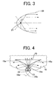
- Fig. 3 shows condition of reflection and refraction of light on a parabolic inside wall 20.
- Light beams emitted from a focus 21 are reflected from the parabolic inside surface 20 to form parallel light beams.
- the light beam to be reflected must have an incident angle larger than the critical angle ⁇ .
- each of both inside walls 15a of the hole is formed by a part of a parabolic line 15b.
- Each of the parabolic reflection surfaces 15a is properly selected from the parabolic lines 15b, so that light beams from the LED 13 may be reflected without uselessness.
- the LED 13 is located at a common focus 22 of both parabolic lines 15b or at a position adjacent the focus so that the light beams are further effectively reflected.
- a flat plane 15c is formed at a vertex of the hole 15 opposite to the LED, so that light beams pass through the surface without reflecting as shown.
- the density of the reflection recesses 16 is progressively increased toward both sides of the light leading plate, the quantity of the reflected light is prevented from reducing at both sides.
- a liquid crystal display panel 23 is uniformly irradiated by the light discharged from the light discharge surface 12a.
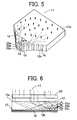
- Figs. 5 and 6 showing the second embodiment of the present invention, three LEDs 25a of red, 25b of green and 25c of blue are provided and arranged in the thickness direction of the light leading plate 12. Other structures are the same as the first embodiment.
- the liquid crystal display panel 23 can be irradiated with various colors by controlling the operation of each of the LEDs 25a, 25b and 25c.
- Fig. 7 is a sectional view showing a part of a modification of the first embodiment.
- a hole 31 is not a through hole, but a blind hole. By changing the depth of the hole 31, the quantity of light discharged from the light discharge surface 12a can be changed.
- Fig. 8 schematically shows the third embodiment.
- the light source unit has two V-shaped reflection planes 27 laterally arranged. LEDs 28 and holes 30 are provided at every corner.
- a wide surface can be irradiated.
- Fig. 9 schematically shows the fourth embodiment of the present invention.
- the light source unit has a light leading plate 32 having a rectangular shape.
- An LED 33 and a hole 34 are provided at one of the corners.
- the light leading plate 32 can be made into the same size and same shape as the liquid crystal display panel. Therefore, the display including the light source unit can be reduced in size.
- At least one hole is formed in the transparent light leading plate at a position above a light source.
- Light beams emitted from the light source is linearly and uniformly diffused by reflection and refraction at the hole.
- the radiating direction of the light beams can be properly adjusted.
- planar light source unit it is possible to uniformly irradiate a large area by a small number of the light sources. As a result, the manufacturing cost of the planar light source unit can be reduced, the unit can be miniaturized.
Abstract
Description
- The present invention relates to a planar light source unit for emitting a linear light beam, which unit is used in a display having a backlight device.
- In recent years, the liquid crystal display device having the backlight device is used in the notebook personal computer, desktop personal computer, and others.
- Fig. 10 is a perspective view showing a conventional planar light source unit, and Fig. 11 is a sectional side view. In the drawings,
reference numeral 10 designates a planar light source unit which comprises a transparent light leading plate 1 made of plastic and formed into a rectangular parallelepiped, and a plurality ofLEDs 2 linearly mounted on a print substrate (not shown) . The light leading member 1 has a light discharge surface la and alight diffusing plane 1b. On thelight diffusing plane 1b, a plurality of embossed grooves or embosseddots 1c are formed, so that light is reflected from thediffusing plane 1b to thelight discharge surface 1a. - On the
light diffusing plane 1b, areflection plate 3 made of a white plastic sheet is attached so as to reflect the light passing through thelight diffusing plate 1b. - The light discharged from the light discharge surface la irradiates a liquid crystal display panel 7 from the back of the panel.
- By adjusting the density of the embossed wrinkle or
dots 1c, or by changing the shape of thedot 1c, it is possible to somewhat equally irradiate the liquid crystal display panel 7. In order to equally irradiate the panel, the number of theLEDs 2 must be increased. However, the increase of the number of the LEDs causes the manufacturing cost, the size of the unit, and power consumption to increase. - An object of the present invention is to provide a planar light source unit which may uniformly irradiate an object with a small number of LEDs, thereby reducing the size of the unit, the manufacturing cost, and the power consumption thereof.
- According to the present invention, there is provided a planar light source unit comprising, at least one light source, a transparent light leading plate provided adjacent to the light source, the light leading plate having a light discharge surface and a light diffusing plane opposite to the light discharge surface, an incidence surface formed in the light leading plate opposite to the light source, a V-shaped light reflecting side formed on a side of the light leading plate at both sides of the incidence surface, at least one hole formed in the light leading plate at a position opposite to the light source, the hole having an inverted triangular shape, opposite sides of the hole being provided for reflecting light beams emitted from the light source.
- A plurality of light reflecting recesses are formed in the V-shaped light reflecting side.
- Each of the opposite sides of the hole is formed by a part of a parabolic line surface.
- The light source may comprise a plurality of light sources.
- The light leading plate may have a rectangular shape, and the light source is provided at one of corners of the rectangular shape.
- The density of the light reflecting recesses becomes increased toward a side far from the light source.
- The light sources may comprise a light source of red, a light source of green, and a light source of blue.
- These and other objects and features of the present invention will become more apparent from the following detailed description with reference to the accompanying drawings.
-
- Fig. 1 is a perspective view showing a planar light source unit of a first embodiment of the present invention;
- Fig. 2 is a sectional view of the unit;
- Fig. 3 is an illustration explaining light paths by a parabolic surface;
- Fig. 4 is a front view showing light paths in the unit of Fig. 1;
- Fig. 5 is a perspective view showing a second embodiment of the present invention;
- Fig. 6 is a sectional view of the second embodiment;
- Fig. 7 is a sectional view showing a part of a modification of the first embodiment;
- Fig. 8 is a schematic illustration showing a third embodiment of the present invention;
- Fig. 9 is a schematic illustration showing a fourth embodiment of the present invention;
- Fig. 10 is a perspective view showing a conventional planar light source unit; and
- Fig. 11 is a sectional side view of the conventional planar light source unit.
-
- Referring to Fig. 1 showing the first embodiment of the present invention, a planar
light source unit 11 comprises a transparentlight leading plate 12 made of plastic and formed into a flat plate, and anLED 13 of white mounted on a print substrate (not shown) as a light source. Thelight leading plate 12 has alight discharge surface 12a, alight diffusing plane 12b, and a V-shaped reflectingside 12c. TheLED 13 is located at a central position of the V-shaped reflectingside 12c of thelight leading plate 12. - In order to uniformly distribute the light quantity on the
LED 13, anincidence portion 14 having a semicircular cylindrical shape is formed at the center of the V-shaped reflection side 12c in front of theLED 13. - On the V-
shaped reflection side 12c, a plurality ofreflection recesses 16 are formed. Eachreflection recess 16 has a semicircular cylindrical shape the axis of which is disposed in the thickness direction of thelight leading plate 12. The distribution density of thereflection recesses 16 becomes large, as the position of the recess becomes far from theLED 13. - The
light leading plate 12 has a central throughhole 15 at a position opposite to theLED 13. Thehole 15 has a substantially inverted isosceles triangular shape. - It is preferable that each side of the
triangular hole 15 has a parabolic inside surface. - The
light diffusing plane 12b has a plurality of embossed grooves or embosseddots 17 as is in the conventional unit. The distribution density of embossed dots becomes increased toward a side far from the light source. - On the
light diffusing plane 12b, a reflection plate orsheet 18 made of a white plastic is attached so as to reflect the light passing through thelight diffusing plate 12b. - Fig. 3 shows condition of reflection and refraction of light on a
parabolic inside wall 20. Light beams emitted from afocus 21 are reflected from the parabolic insidesurface 20 to form parallel light beams. The light beam to be reflected must have an incident angle larger than the critical angle . - Referring to Fig. 4, each of both inside
walls 15a of the hole is formed by a part of aparabolic line 15b. Each of theparabolic reflection surfaces 15a is properly selected from theparabolic lines 15b, so that light beams from theLED 13 may be reflected without uselessness. Furthermore, theLED 13 is located at acommon focus 22 of bothparabolic lines 15b or at a position adjacent the focus so that the light beams are further effectively reflected. - However, if the light is entirely reflected from the
inside walls 15a, the light quantity discharged from a region immediately upper portion of the LED decreases, rendering an irradiated surface dark. In order to remove such a defect, aflat plane 15c is formed at a vertex of thehole 15 opposite to the LED, so that light beams pass through the surface without reflecting as shown. - In addition, since the density of the
reflection recesses 16 is progressively increased toward both sides of the light leading plate, the quantity of the reflected light is prevented from reducing at both sides. - Thus, a liquid
crystal display panel 23 is uniformly irradiated by the light discharged from thelight discharge surface 12a. - Referring to Figs. 5 and 6 showing the second embodiment of the present invention, three
LEDs 25a of red, 25b of green and 25c of blue are provided and arranged in the thickness direction of thelight leading plate 12. Other structures are the same as the first embodiment. - In accordance with the second embodiment, the liquid
crystal display panel 23 can be irradiated with various colors by controlling the operation of each of theLEDs - Fig. 7 is a sectional view showing a part of a modification of the first embodiment. A
hole 31 is not a through hole, but a blind hole. By changing the depth of thehole 31, the quantity of light discharged from thelight discharge surface 12a can be changed. - Fig. 8 schematically shows the third embodiment. The light source unit has two V-shaped reflection planes 27 laterally arranged.
LEDs 28 and holes 30 are provided at every corner. - According to the third embodiment, a wide surface can be irradiated.
- Fig. 9 schematically shows the fourth embodiment of the present invention.
- The light source unit has a light leading
plate 32 having a rectangular shape. AnLED 33 and ahole 34 are provided at one of the corners. - According to the fourth embodiment, the light leading
plate 32 can be made into the same size and same shape as the liquid crystal display panel. Therefore, the display including the light source unit can be reduced in size. - In accordance with the present invention, at least one hole is formed in the transparent light leading plate at a position above a light source. Light beams emitted from the light source is linearly and uniformly diffused by reflection and refraction at the hole. By changing the shape and the number of hole, the radiating direction of the light beams can be properly adjusted.
- Thus, it is possible to uniformly irradiate a large area by a small number of the light sources. As a result, the manufacturing cost of the planar light source unit can be reduced, the unit can be miniaturized.
- While the invention has been described in conjunction with preferred specific embodiment thereof, it will be understood that this description is intended to illustrate and not limit the scope of the invention, which is defined by the following claims.
Claims (22)
- A planar light source unit comprising:a transparent light leading plate;the light leading plate having a light discharge surface and a light diffusing plane opposite to the light discharge surface;a V-shaped light reflecting side formed on a side of the light leading plate;an incidence surface formed at a vertex of the V-shape of the V-shaped light reflecting side;at least one light source provided opposite to the incidence surface;at least one hole formed in the light leading plate at a position opposite to the incidence surface;the hole having an inverted triangular shape, opposite sides of the hole being provided for reflecting light beams emitted from the light source;
- The planar light source unit according to claim 1 further comprising a plurality of light reflecting recesses formed in the V-shaped light reflecting side.
- The planar light source unit according to claim 1 wherein the incidence surface has a semicircular cylindrical shape.
- The planar light source unit according to claim 1 wherein each of the opposite sides of the hole is formed by a part of a parabolic line surface.
- The planar light source unit according to claim 1 wherein the hole is a through hole.
- The planar light source unit according to claim 1 wherein the hole is a blind hole.
- The planar light source unit according to claim 1 wherein the light source comprises plural light sources.
- The planar light source unit according to claim 1 wherein the light leading plate has a square shape, and the light source is provided at one of corners of the square shape.
- The planar light source unit according to claim 1 wherein the light leading plate has plural V-shaped light reflecting sides, and the light source is provided opposite to the incidence surface of each light reflecting side.
- The planar light source unit according to claim 1 wherein the light source is an LED.
- The planar light source unit according to claim 1 wherein a plurality of embossed grooves are formed on the light diffusing plane of the light leading plate.
- The planar light source unit according to claim 1 wherein a plurality of embossed dots are formed on the light diffusing plane of the light leading plate.
- The planar light source unit according to claim 1 further comprising a reflecting plate of white attached on the light diffusing plane.
- The planar light source unit according to claim 1 further comprising a reflecting sheet of white attached on the light diffusing plane.
- The planar light source unit according to claim 1 wherein the hole has a flat plane at a vertex opposite to the light source.
- The planar light source unit according to claim 2 wherein the light reflecting recess has a semicircular cylindrical shape.
- The planar light source unit according to claim 2 wherein the distribution density of the light reflecting recesses becomes increased toward a side far from the light source.
- The planar light source unit according to claim 7 wherein the light sources comprise a light source of red, a light source of green, and a light source of blue.
- The planar light source unit according to claim 7 wherein the light sources are arranged in the thickness direction of the light leading plate.
- The planar light source unit according to claim 10 wherein the LED is a white LED.
- The planar light source unit according to claim 12 wherein the distribution density of the dots becomes increased toward a side far from the light source.
- The planar light source unit according to claim 16 wherein the light reflecting recesses are arranged in parallel with respect to the thickness direction of the light leading plate.
Applications Claiming Priority (2)
| Application Number | Priority Date | Filing Date | Title |
|---|---|---|---|
| JP17207498 | 1998-06-05 | ||
| JP17207498A JP4159059B2 (en) | 1998-06-05 | 1998-06-05 | Planar light source unit |
Publications (2)
| Publication Number | Publication Date |
|---|---|
| EP0962694A1 true EP0962694A1 (en) | 1999-12-08 |
| EP0962694B1 EP0962694B1 (en) | 2009-09-09 |
Family
ID=15935068
Family Applications (1)
| Application Number | Title | Priority Date | Filing Date |
|---|---|---|---|
| EP99304211A Expired - Lifetime EP0962694B1 (en) | 1998-06-05 | 1999-05-28 | Planar light source unit |
Country Status (4)
| Country | Link |
|---|---|
| US (1) | US6139163A (en) |
| EP (1) | EP0962694B1 (en) |
| JP (1) | JP4159059B2 (en) |
| DE (1) | DE69941379D1 (en) |
Cited By (20)
| Publication number | Priority date | Publication date | Assignee | Title |
|---|---|---|---|---|
| EP1067329A1 (en) * | 1999-07-07 | 2001-01-10 | Philips Corporate Intellectual Property GmbH | Screen with backlight illumination |
| EP1113218A1 (en) * | 1999-12-28 | 2001-07-04 | Fujitsu Kasei Limited | Lighting apparatus for a display |
| DE10032927A1 (en) * | 2000-07-06 | 2002-01-17 | Hella Kg Hueck & Co | Lighting device e.g. for illuminating motor vehicle interior, uses plate-shaped or bar-type light-guide |
| DE10058349A1 (en) * | 2000-11-23 | 2002-05-29 | Guenter F Epple | Illuminating unit comprises a transparent plate with a row of parallel bores which are located in one of the plate edges and accommodate light emitting diodes |
| WO2003071321A1 (en) * | 2002-02-22 | 2003-08-28 | Lumileds Lighting Netherlands B.V. | Compact lighting system and display device |
| US6666562B2 (en) | 2000-05-16 | 2003-12-23 | Polar Electro Oy | Connecting light source to background plate |
| EP1450183A1 (en) * | 2003-02-21 | 2004-08-25 | Minebea Co., Ltd. | Spread illuminating apparatus with light conductive plate having polygonal configuration |
| WO2004094231A1 (en) * | 2003-04-04 | 2004-11-04 | Honeywell International Inc. | Led based light guide for aircraft formation lighting |
| EP1521229A2 (en) * | 2003-09-30 | 2005-04-06 | Siemens Aktiengesellschaft | Display with back-lighting system |
| EP1910736A2 (en) * | 2005-07-28 | 2008-04-16 | Light Prescriptions Innovators, LLC. | Etendue-conserving illumination-optics for backlights and frontlights |
| EP2264493A1 (en) * | 2009-06-16 | 2010-12-22 | Gerhard Dipl.-Phys. Karl | Lightguide with reflectors for even area illumination |
| DE102005024083B4 (en) * | 2004-05-28 | 2011-03-17 | Epistar Corp. | Flat, light-emitting device |
| CN102331598A (en) * | 2011-09-19 | 2012-01-25 | 苏州向隆塑胶有限公司 | Light guide plate, manufacturing method thereof and light source device |
| CN101201147B (en) * | 2006-12-14 | 2012-10-10 | 鸿富锦精密工业(深圳)有限公司 | Even light-guiding mechanism |
| DE102005024084B4 (en) * | 2004-05-28 | 2012-11-29 | Epistar Corp. | Area light source device |
| WO2014207328A1 (en) * | 2013-06-28 | 2014-12-31 | Valeo Systemes Thermiques | Lighting device |
| EP2927731A1 (en) * | 2014-04-01 | 2015-10-07 | Valeo Lighting Hubei Technical Center Co Ltd | An led light-mixing device and a lighting and/or signal indication device |
| DE102007005932B4 (en) | 2006-04-27 | 2018-10-04 | Zkw Group Gmbh | Vehicle headlamp with light guide |
| US10683985B2 (en) | 2018-01-19 | 2020-06-16 | Heathco Llc | Security light with diffusing light panel |
| US10788617B2 (en) | 2018-01-19 | 2020-09-29 | HeatchCo LLC | Outside light with diffusing light panel |
Families Citing this family (81)
| Publication number | Priority date | Publication date | Assignee | Title |
|---|---|---|---|---|
| JP3458823B2 (en) * | 1999-05-11 | 2003-10-20 | 日亜化学工業株式会社 | Surface emitting device |
| JP4862208B2 (en) * | 1999-12-27 | 2012-01-25 | パナソニック株式会社 | LCD backlight structure |
| KR100701014B1 (en) | 2000-11-22 | 2007-03-29 | 삼성전자주식회사 | A light guide plate, a liquid crystal display module and a liquid crystal display device having the same |
| JP4260358B2 (en) * | 2000-12-01 | 2009-04-30 | 日本ライツ株式会社 | Light guide plate and flat illumination device |
| JP2002296425A (en) * | 2001-03-29 | 2002-10-09 | Enplas Corp | Light transmission plate, surface light source device and liquid crystal display |
| US6738051B2 (en) | 2001-04-06 | 2004-05-18 | 3M Innovative Properties Company | Frontlit illuminated touch panel |
| US6592234B2 (en) | 2001-04-06 | 2003-07-15 | 3M Innovative Properties Company | Frontlit display |
| US6568822B2 (en) | 2001-04-06 | 2003-05-27 | 3M Innovative Properties Company | Linear illumination source |
| JP4152605B2 (en) * | 2001-05-30 | 2008-09-17 | 株式会社エンプラス | Light guide plate, surface light source device, and liquid crystal display |
| KR20030008790A (en) * | 2001-07-20 | 2003-01-29 | 삼성전자 주식회사 | Liquid crystal display device |
| JP4592049B2 (en) * | 2001-09-12 | 2010-12-01 | シチズン電子株式会社 | Planar light source unit |
| US6948840B2 (en) * | 2001-11-16 | 2005-09-27 | Everbrite, Llc | Light emitting diode light bar |
| JP3801032B2 (en) * | 2001-11-29 | 2006-07-26 | 日本電気株式会社 | Light source and liquid crystal display device using the light source |
| KR20040019202A (en) * | 2002-08-27 | 2004-03-05 | 하철근 | Unified light guide bar |
| US7084935B2 (en) * | 2002-08-28 | 2006-08-01 | Adaptive Micro Systems, Llc | Display device with molded light guide |
| TW558015U (en) * | 2002-12-06 | 2003-10-11 | Hon Hai Prec Ind Co Ltd | Backlight module |
| KR100499140B1 (en) * | 2003-01-07 | 2005-07-04 | 삼성전자주식회사 | Backlight unit |
| TWM243658U (en) * | 2003-06-13 | 2004-09-11 | Hon Hai Prec Ind Co Ltd | Planar light source device |
| KR100989338B1 (en) * | 2003-07-01 | 2010-10-25 | 삼성전자주식회사 | Backlight assembly and liquid crystal display device having the same |
| US7510316B2 (en) * | 2003-07-14 | 2009-03-31 | Koninklijke Philips Electronics N.V. | Ultra compact illumination system for display systems |
| US7182492B1 (en) * | 2003-12-22 | 2007-02-27 | Robert Louis Walter | License plate system having enhanced illumination |
| CN100376958C (en) * | 2004-02-19 | 2008-03-26 | 鸿富锦精密工业(深圳)有限公司 | Light board and backlight module set |
| JP4020397B2 (en) * | 2004-06-14 | 2007-12-12 | 惠次 飯村 | Surface light source using point light source |
| TWI259313B (en) * | 2004-10-19 | 2006-08-01 | Ind Tech Res Inst | Light-guide plate and method for manufacturing thereof |
| JP4743846B2 (en) * | 2005-05-10 | 2011-08-10 | シチズン電子株式会社 | Optical communication apparatus and information equipment using the same |
| CN1912703A (en) * | 2005-08-12 | 2007-02-14 | 鸿富锦精密工业(深圳)有限公司 | Direct light backlight mould set and its transmitting plate |
| TW200708853A (en) * | 2005-08-30 | 2007-03-01 | Ind Tech Res Inst | Light-guide plate and the backlight module having the same |
| TWM284913U (en) * | 2005-09-09 | 2006-01-01 | Innolux Display Corp | Light guide plate, backlight module and liquid crystal display device |
| US20070086179A1 (en) * | 2005-10-14 | 2007-04-19 | Radiant Opto-Electronics Corporation | Light mixing plate and direct backlight module |
| KR20070043102A (en) * | 2005-10-20 | 2007-04-25 | 삼성전자주식회사 | Light guide unit for point light source, backlight assembly having the light guide unit and display device having the same |
| KR100735410B1 (en) * | 2005-11-17 | 2007-07-04 | 삼성전기주식회사 | LED illumination system having light guide panel distributing incident rays evenly |
| KR100826401B1 (en) * | 2005-12-02 | 2008-05-02 | 삼성전기주식회사 | Led backlight apparatus |
| TWI327666B (en) * | 2006-03-17 | 2010-07-21 | Hon Hai Prec Ind Co Ltd | Light guide plate and backlight module using the same |
| KR100784023B1 (en) * | 2006-03-20 | 2007-12-07 | 엘지이노텍 주식회사 | Backlight unit and LCD having the same |
| CN101078795B (en) * | 2006-05-24 | 2010-05-12 | 清华大学 | Light conducting board and backlight module |
| ITMI20061203A1 (en) * | 2006-06-22 | 2007-12-23 | X | X |
| US20080007964A1 (en) * | 2006-07-05 | 2008-01-10 | Tai-Yen Lin | Light guiding structure |
| EP2064487A4 (en) | 2006-07-14 | 2010-09-01 | Light Prescriptions Innovators | Brightness-enhancing film |
| JP2008084848A (en) * | 2006-08-30 | 2008-04-10 | Seiko Instruments Inc | Lighting apparatus, and display device provided with the same |
| KR100818278B1 (en) * | 2006-10-16 | 2008-04-01 | 삼성전자주식회사 | Illuminating device for liquid crystal display |
| EP2082166A1 (en) * | 2006-10-16 | 2009-07-29 | Koninklijke Philips Electronics N.V. | Lighting device |
| CN100529888C (en) * | 2006-12-22 | 2009-08-19 | 群康科技(深圳)有限公司 | Back light module unit and LCD |
| CN101617252B (en) * | 2006-12-29 | 2012-06-20 | 莫迪尼斯有限公司 | Incoupling structure for lighting applications |
| EP2106516A2 (en) * | 2007-01-19 | 2009-10-07 | Philips Intellectual Property & Standards GmbH | Illumination device |
| US20080188277A1 (en) | 2007-02-01 | 2008-08-07 | Ritter Janice E | Electronic Game Device And Method Of Using The Same |
| US20090059553A1 (en) * | 2007-05-08 | 2009-03-05 | Tai-Yen Lin | Light guiding structure and manufacturing of the same |
| JP2009146874A (en) * | 2007-11-22 | 2009-07-02 | Seiko Precision Inc | Illumination device, and manufacturing method of illumination device |
| TW200933247A (en) * | 2008-01-24 | 2009-08-01 | Nano Prec Corp | Side-type backlight module |
| WO2009103517A1 (en) * | 2008-02-22 | 2009-08-27 | Osram Opto Semiconductors Gmbh | Optical arrangement and production method |
| US8002450B2 (en) * | 2008-10-06 | 2011-08-23 | Rambus Inc. | Cavity reflector light injection for flat panel displays |
| TWI370302B (en) * | 2008-12-25 | 2012-08-11 | Au Optronics Corp | A light guide plate having lateral optical structures and a backlight module having the light guide plate |
| JP5601042B2 (en) * | 2010-06-11 | 2014-10-08 | 三菱電機株式会社 | Planar light source device and display device |
| TWI526898B (en) * | 2011-02-11 | 2016-03-21 | 原相科技股份有限公司 | Optical touch panel and light guide module thereof |
| CN102661527B (en) * | 2012-03-29 | 2014-03-26 | 深圳市华星光电技术有限公司 | Backlight module and liquid crystal display |
| US20130258716A1 (en) * | 2012-03-29 | 2013-10-03 | Shenzhen China Star Optoelectronics Technology Co., Ltd. | Blacklight module and liquid crystal display |
| CN102721996A (en) * | 2012-06-06 | 2012-10-10 | 华为终端有限公司 | Light guide device, light emitting equipment, electronic equipment and key |
| CN103017090A (en) * | 2013-01-16 | 2013-04-03 | 深圳市华星光电技术有限公司 | Light leading-in system, side-inlet backlight module and liquid crystal display |
| US9366396B2 (en) | 2013-01-30 | 2016-06-14 | Cree, Inc. | Optical waveguide and lamp including same |
| US10436969B2 (en) | 2013-01-30 | 2019-10-08 | Ideal Industries Lighting Llc | Optical waveguide and luminaire incorporating same |
| US9442243B2 (en) * | 2013-01-30 | 2016-09-13 | Cree, Inc. | Waveguide bodies including redirection features and methods of producing same |
| US8911132B1 (en) * | 2013-03-15 | 2014-12-16 | Cooper Technologies Company | Edgelit optic entrance features |
| US9798072B2 (en) | 2013-03-15 | 2017-10-24 | Cree, Inc. | Optical element and method of forming an optical element |
| US10209429B2 (en) | 2013-03-15 | 2019-02-19 | Cree, Inc. | Luminaire with selectable luminous intensity pattern |
| TW201441682A (en) * | 2013-04-23 | 2014-11-01 | Hon Hai Prec Ind Co Ltd | Light guide plate and back light module |
| AU2014216006B2 (en) * | 2013-09-27 | 2018-07-19 | Omron Corporation | Light Guide Body and Light-Emitting Device |
| CN104597553B (en) * | 2013-10-30 | 2017-09-12 | 纬创资通股份有限公司 | Light guide plate |
| US9651740B2 (en) | 2014-01-09 | 2017-05-16 | Cree, Inc. | Extraction film for optical waveguide and method of producing same |
| US11719882B2 (en) | 2016-05-06 | 2023-08-08 | Ideal Industries Lighting Llc | Waveguide-based light sources with dynamic beam shaping |
| US10416377B2 (en) | 2016-05-06 | 2019-09-17 | Cree, Inc. | Luminaire with controllable light emission |
| EP3627040A1 (en) * | 2018-09-20 | 2020-03-25 | Nederlandse Organisatie voor toegepast- natuurwetenschappelijk onderzoek TNO | Hot spot reduction in segmented flexible light guides |
| TW201935728A (en) | 2018-01-30 | 2019-09-01 | 荷蘭商荷蘭Tno自然科學組織公司 | Hot spot reduction in segmented flexible light guides |
| CN208457847U (en) * | 2018-02-09 | 2019-02-01 | 法雷奥市光(中国)车灯有限公司 | Light guide member, car light and motor vehicles |
| WO2020000210A1 (en) * | 2018-06-26 | 2020-01-02 | 深圳市大疆创新科技有限公司 | Indication device and battery assembly |
| DE102018211527A1 (en) * | 2018-07-11 | 2020-01-16 | Robert Bosch Gmbh | light guide |
| CN110792948B (en) * | 2018-08-01 | 2023-08-18 | 北京京东尚科信息技术有限公司 | Light guide structure, light structure and audio amplifier |
| CZ307985B6 (en) * | 2018-08-03 | 2019-10-02 | Varroc Lighting Systems, s.r.o. | A light guide optical unit and a light guide optical system comprising light guide optical units |
| CN109519870A (en) * | 2018-12-28 | 2019-03-26 | 马瑞利汽车零部件(芜湖)有限公司 | Realize the optical system of uniformly light-emitting |
| DE102019106221A1 (en) * | 2019-03-12 | 2020-09-17 | HELLA GmbH & Co. KGaA | Lighting device for vehicles |
| CN110045452A (en) * | 2019-03-28 | 2019-07-23 | 武汉华星光电技术有限公司 | Light guide plate, backlight module and display device |
| FR3110978B1 (en) * | 2020-05-28 | 2022-10-28 | Commissariat Energie Atomique | LIGHT DISTRIBUTION DEVICE BASED ON A PLANAR WAVE GUIDE |
| TW202326256A (en) * | 2021-12-28 | 2023-07-01 | 華碩電腦股份有限公司 | Backlight module |
Citations (6)
| Publication number | Priority date | Publication date | Assignee | Title |
|---|---|---|---|---|
| US4673254A (en) * | 1985-07-30 | 1987-06-16 | Tokyo Keiki Co., Ltd. | Back-reflection type light diffusing apparatus |
| US4770499A (en) | 1986-01-17 | 1988-09-13 | Stanley Electric Co., Ltd. | Illuminated liquid crystal display apparatus with bent, indicia-bearing light guide |
| US5197792A (en) * | 1992-04-21 | 1993-03-30 | General Motors Corporation | Illuminator device for a display panel |
| GB2270409A (en) | 1992-09-02 | 1994-03-09 | Motorola Inc | Light wedge for distributing light across a display device |
| EP0732679A1 (en) * | 1995-03-16 | 1996-09-18 | Hayashi Telempu Co., Ltd. | Display panel for instruments installed in vehicles |
| EP0751340A2 (en) * | 1995-06-27 | 1997-01-02 | Lumitex, Inc. | Light emitting panel assemblies |
Family Cites Families (12)
| Publication number | Priority date | Publication date | Assignee | Title |
|---|---|---|---|---|
| US3609960A (en) * | 1968-11-28 | 1971-10-05 | Alduc Sa | Timepiece dial |
| JPS57146286A (en) * | 1981-03-04 | 1982-09-09 | Mitsubishi Electric Corp | Lighting apparatus |
| US4625262A (en) * | 1983-07-08 | 1986-11-25 | Yazaki Corporation | Pointer illuminating structure in measuring instrument |
| US5083240A (en) * | 1989-08-24 | 1992-01-21 | Technophone Limited | Light guide |
| US5515244A (en) * | 1995-04-03 | 1996-05-07 | Apple Computer, Inc. | Light-transmitting pipe |
| JPH09113907A (en) * | 1995-10-17 | 1997-05-02 | Nippon Chemitec Kk | Light transmission plate and surface type illuminating body using the same |
| US5746493A (en) * | 1996-03-08 | 1998-05-05 | Ericsson Inc. | Light guide for a display or keyboard |
| JPH10123329A (en) * | 1996-10-16 | 1998-05-15 | Seiko Epson Corp | Lighting device and liquid crystal display device |
| US5727862A (en) * | 1996-11-25 | 1998-03-17 | Taiwan Liton Electronic Co., Ltd. | LED back light assembly |
| JP3516005B2 (en) * | 1997-01-17 | 2004-04-05 | オムロン株式会社 | Surface light source device |
| JPH10260404A (en) * | 1997-03-18 | 1998-09-29 | Seiko Epson Corp | Lighting device, liquid-crystal display device, and electronic equipment |
| JPH10293213A (en) * | 1997-04-22 | 1998-11-04 | Toshiba Corp | Backlight device |
-
1998
- 1998-06-05 JP JP17207498A patent/JP4159059B2/en not_active Expired - Lifetime
-
1999
- 1999-05-28 EP EP99304211A patent/EP0962694B1/en not_active Expired - Lifetime
- 1999-05-28 DE DE69941379T patent/DE69941379D1/en not_active Expired - Lifetime
- 1999-06-04 US US09/325,634 patent/US6139163A/en not_active Expired - Lifetime
Patent Citations (6)
| Publication number | Priority date | Publication date | Assignee | Title |
|---|---|---|---|---|
| US4673254A (en) * | 1985-07-30 | 1987-06-16 | Tokyo Keiki Co., Ltd. | Back-reflection type light diffusing apparatus |
| US4770499A (en) | 1986-01-17 | 1988-09-13 | Stanley Electric Co., Ltd. | Illuminated liquid crystal display apparatus with bent, indicia-bearing light guide |
| US5197792A (en) * | 1992-04-21 | 1993-03-30 | General Motors Corporation | Illuminator device for a display panel |
| GB2270409A (en) | 1992-09-02 | 1994-03-09 | Motorola Inc | Light wedge for distributing light across a display device |
| EP0732679A1 (en) * | 1995-03-16 | 1996-09-18 | Hayashi Telempu Co., Ltd. | Display panel for instruments installed in vehicles |
| EP0751340A2 (en) * | 1995-06-27 | 1997-01-02 | Lumitex, Inc. | Light emitting panel assemblies |
Cited By (28)
| Publication number | Priority date | Publication date | Assignee | Title |
|---|---|---|---|---|
| EP1067329A1 (en) * | 1999-07-07 | 2001-01-10 | Philips Corporate Intellectual Property GmbH | Screen with backlight illumination |
| EP1113218A1 (en) * | 1999-12-28 | 2001-07-04 | Fujitsu Kasei Limited | Lighting apparatus for a display |
| US6474826B1 (en) | 1999-12-28 | 2002-11-05 | Fujitsu Kasei Limited | Lighting apparatus |
| US6666562B2 (en) | 2000-05-16 | 2003-12-23 | Polar Electro Oy | Connecting light source to background plate |
| DE10032927A1 (en) * | 2000-07-06 | 2002-01-17 | Hella Kg Hueck & Co | Lighting device e.g. for illuminating motor vehicle interior, uses plate-shaped or bar-type light-guide |
| DE10058349A1 (en) * | 2000-11-23 | 2002-05-29 | Guenter F Epple | Illuminating unit comprises a transparent plate with a row of parallel bores which are located in one of the plate edges and accommodate light emitting diodes |
| US7267469B2 (en) | 2002-02-22 | 2007-09-11 | Philips Lumileds Lighting Company, Llc | Compact lighting system and display device |
| WO2003071321A1 (en) * | 2002-02-22 | 2003-08-28 | Lumileds Lighting Netherlands B.V. | Compact lighting system and display device |
| EP1450183A1 (en) * | 2003-02-21 | 2004-08-25 | Minebea Co., Ltd. | Spread illuminating apparatus with light conductive plate having polygonal configuration |
| US7056004B2 (en) | 2003-02-21 | 2006-06-06 | Minebea Co., Ltd. | Spread illuminating apparatus with light conductive plate having polygonal configuration |
| WO2004094231A1 (en) * | 2003-04-04 | 2004-11-04 | Honeywell International Inc. | Led based light guide for aircraft formation lighting |
| US7278766B2 (en) | 2003-04-04 | 2007-10-09 | Honeywell International Inc. | LED based light guide for dual mode aircraft formation lighting |
| EP1521229A2 (en) * | 2003-09-30 | 2005-04-06 | Siemens Aktiengesellschaft | Display with back-lighting system |
| EP1521229A3 (en) * | 2003-09-30 | 2006-05-10 | Siemens Aktiengesellschaft | Display with back-lighting system |
| DE102005024083B4 (en) * | 2004-05-28 | 2011-03-17 | Epistar Corp. | Flat, light-emitting device |
| DE102005024084B4 (en) * | 2004-05-28 | 2012-11-29 | Epistar Corp. | Area light source device |
| EP1910736A2 (en) * | 2005-07-28 | 2008-04-16 | Light Prescriptions Innovators, LLC. | Etendue-conserving illumination-optics for backlights and frontlights |
| EP1910736A4 (en) * | 2005-07-28 | 2010-05-26 | Light Prescriptions Innovators | Etendue-conserving illumination-optics for backlights and frontlights |
| DE102007005932B4 (en) | 2006-04-27 | 2018-10-04 | Zkw Group Gmbh | Vehicle headlamp with light guide |
| CN101201147B (en) * | 2006-12-14 | 2012-10-10 | 鸿富锦精密工业(深圳)有限公司 | Even light-guiding mechanism |
| EP2264493A1 (en) * | 2009-06-16 | 2010-12-22 | Gerhard Dipl.-Phys. Karl | Lightguide with reflectors for even area illumination |
| CN102331598A (en) * | 2011-09-19 | 2012-01-25 | 苏州向隆塑胶有限公司 | Light guide plate, manufacturing method thereof and light source device |
| WO2014207328A1 (en) * | 2013-06-28 | 2014-12-31 | Valeo Systemes Thermiques | Lighting device |
| FR3007823A1 (en) * | 2013-06-28 | 2015-01-02 | Valeo Systemes Thermiques | LIGHT DEVICE |
| CN105814363A (en) * | 2013-06-28 | 2016-07-27 | 法雷奥热系统公司 | Lighting device |
| EP2927731A1 (en) * | 2014-04-01 | 2015-10-07 | Valeo Lighting Hubei Technical Center Co Ltd | An led light-mixing device and a lighting and/or signal indication device |
| US10683985B2 (en) | 2018-01-19 | 2020-06-16 | Heathco Llc | Security light with diffusing light panel |
| US10788617B2 (en) | 2018-01-19 | 2020-09-29 | HeatchCo LLC | Outside light with diffusing light panel |
Also Published As
| Publication number | Publication date |
|---|---|
| JP4159059B2 (en) | 2008-10-01 |
| EP0962694B1 (en) | 2009-09-09 |
| DE69941379D1 (en) | 2009-10-22 |
| JPH11353917A (en) | 1999-12-24 |
| US6139163A (en) | 2000-10-31 |
Similar Documents
| Publication | Publication Date | Title |
|---|---|---|
| US6139163A (en) | Planar light source unit | |
| US7690831B2 (en) | Surface light source device | |
| US7206491B2 (en) | Light guide device and backlight module using the same | |
| EP2202447A1 (en) | Hollow planar illuminating device | |
| EP1602949B1 (en) | Spread illuminating apparatus | |
| US7731407B2 (en) | Display device | |
| US7364336B2 (en) | Plane light source device and display device provided with the same | |
| US20040125590A1 (en) | Light guide plate and surface light source | |
| JP2002196151A (en) | Light guide plate | |
| JP2006253139A (en) | Backlight module | |
| US20030048630A1 (en) | Planar light source unit | |
| US20090016067A1 (en) | Optical plate and backlight module using the same | |
| EP2461205A2 (en) | Backlight device and image display using the same | |
| KR100438524B1 (en) | BackLight Unit | |
| JP2001035229A (en) | Surface light source unit | |
| US20080266898A1 (en) | Optical plate and backlight module using the same | |
| JP2004355883A (en) | Light guide plate, surface light source device, and image display device | |
| JP2010067600A (en) | Light source device and illuminating device using this light source device | |
| JP2007080800A (en) | Light guide plate of backlight unit | |
| JPH11306831A (en) | Surface light source unit | |
| JP5401649B2 (en) | Lighting device | |
| JP5401650B2 (en) | Lighting device | |
| US6211929B1 (en) | Surface light source device of side light type and liquid crystal display | |
| TWI722799B (en) | Surface light source apparatus and liquid crystal display device | |
| WO2013088594A1 (en) | Backlight apparatus and liquid crystal display apparatus |
Legal Events
| Date | Code | Title | Description |
|---|---|---|---|
| PUAI | Public reference made under article 153(3) epc to a published international application that has entered the european phase |
Free format text: ORIGINAL CODE: 0009012 |
|
| AK | Designated contracting states |
Kind code of ref document: A1 Designated state(s): DE FI FR GB SE |
|
| AX | Request for extension of the european patent |
Free format text: AL;LT;LV;MK;RO;SI |
|
| 17P | Request for examination filed |
Effective date: 19991217 |
|
| AKX | Designation fees paid |
Free format text: DE FI FR GB SE |
|
| GRAP | Despatch of communication of intention to grant a patent |
Free format text: ORIGINAL CODE: EPIDOSNIGR1 |
|
| GRAS | Grant fee paid |
Free format text: ORIGINAL CODE: EPIDOSNIGR3 |
|
| GRAA | (expected) grant |
Free format text: ORIGINAL CODE: 0009210 |
|
| AK | Designated contracting states |
Kind code of ref document: B1 Designated state(s): DE FI FR GB SE |
|
| REG | Reference to a national code |
Ref country code: GB Ref legal event code: FG4D |
|
| REF | Corresponds to: |
Ref document number: 69941379 Country of ref document: DE Date of ref document: 20091022 Kind code of ref document: P |
|
| PG25 | Lapsed in a contracting state [announced via postgrant information from national office to epo] |
Ref country code: SE Free format text: LAPSE BECAUSE OF FAILURE TO SUBMIT A TRANSLATION OF THE DESCRIPTION OR TO PAY THE FEE WITHIN THE PRESCRIBED TIME-LIMIT Effective date: 20090909 Ref country code: FI Free format text: LAPSE BECAUSE OF FAILURE TO SUBMIT A TRANSLATION OF THE DESCRIPTION OR TO PAY THE FEE WITHIN THE PRESCRIBED TIME-LIMIT Effective date: 20090909 |
|
| PLBE | No opposition filed within time limit |
Free format text: ORIGINAL CODE: 0009261 |
|
| STAA | Information on the status of an ep patent application or granted ep patent |
Free format text: STATUS: NO OPPOSITION FILED WITHIN TIME LIMIT |
|
| 26N | No opposition filed |
Effective date: 20100610 |
|
| GBPC | Gb: european patent ceased through non-payment of renewal fee |
Effective date: 20100528 |
|
| REG | Reference to a national code |
Ref country code: FR Ref legal event code: ST Effective date: 20110131 |
|
| PG25 | Lapsed in a contracting state [announced via postgrant information from national office to epo] |
Ref country code: FR Free format text: LAPSE BECAUSE OF NON-PAYMENT OF DUE FEES Effective date: 20100531 |
|
| PG25 | Lapsed in a contracting state [announced via postgrant information from national office to epo] |
Ref country code: GB Free format text: LAPSE BECAUSE OF NON-PAYMENT OF DUE FEES Effective date: 20100528 |
|
| REG | Reference to a national code |
Ref country code: DE Ref legal event code: R082 Ref document number: 69941379 Country of ref document: DE Representative=s name: WEICKMANN & WEICKMANN PATENT- UND RECHTSANWAEL, DE Ref country code: DE Ref legal event code: R082 Ref document number: 69941379 Country of ref document: DE Representative=s name: WEICKMANN & WEICKMANN PATENTANWAELTE - RECHTSA, DE Ref country code: DE Ref legal event code: R082 Ref document number: 69941379 Country of ref document: DE Representative=s name: PATENTANWAELTE WEICKMANN & WEICKMANN, DE |
|
| PGFP | Annual fee paid to national office [announced via postgrant information from national office to epo] |
Ref country code: DE Payment date: 20180515 Year of fee payment: 20 |
|
| REG | Reference to a national code |
Ref country code: DE Ref legal event code: R071 Ref document number: 69941379 Country of ref document: DE |