EP0959370A2 - Vehicle radar method - Google Patents
Vehicle radar method Download PDFInfo
- Publication number
- EP0959370A2 EP0959370A2 EP99108990A EP99108990A EP0959370A2 EP 0959370 A2 EP0959370 A2 EP 0959370A2 EP 99108990 A EP99108990 A EP 99108990A EP 99108990 A EP99108990 A EP 99108990A EP 0959370 A2 EP0959370 A2 EP 0959370A2
- Authority
- EP
- European Patent Office
- Prior art keywords
- detection
- radar
- ffts
- track
- radar method
- Prior art date
- Legal status (The legal status is an assumption and is not a legal conclusion. Google has not performed a legal analysis and makes no representation as to the accuracy of the status listed.)
- Withdrawn
Links
Images
Classifications
-
- G—PHYSICS
- G01—MEASURING; TESTING
- G01S—RADIO DIRECTION-FINDING; RADIO NAVIGATION; DETERMINING DISTANCE OR VELOCITY BY USE OF RADIO WAVES; LOCATING OR PRESENCE-DETECTING BY USE OF THE REFLECTION OR RERADIATION OF RADIO WAVES; ANALOGOUS ARRANGEMENTS USING OTHER WAVES
- G01S7/00—Details of systems according to groups G01S13/00, G01S15/00, G01S17/00
- G01S7/02—Details of systems according to groups G01S13/00, G01S15/00, G01S17/00 of systems according to group G01S13/00
- G01S7/35—Details of non-pulse systems
- G01S7/352—Receivers
- G01S7/356—Receivers involving particularities of FFT processing
-
- G—PHYSICS
- G01—MEASURING; TESTING
- G01S—RADIO DIRECTION-FINDING; RADIO NAVIGATION; DETERMINING DISTANCE OR VELOCITY BY USE OF RADIO WAVES; LOCATING OR PRESENCE-DETECTING BY USE OF THE REFLECTION OR RERADIATION OF RADIO WAVES; ANALOGOUS ARRANGEMENTS USING OTHER WAVES
- G01S7/00—Details of systems according to groups G01S13/00, G01S15/00, G01S17/00
- G01S7/02—Details of systems according to groups G01S13/00, G01S15/00, G01S17/00 of systems according to group G01S13/00
- G01S7/35—Details of non-pulse systems
- G01S7/352—Receivers
-
- G—PHYSICS
- G01—MEASURING; TESTING
- G01S—RADIO DIRECTION-FINDING; RADIO NAVIGATION; DETERMINING DISTANCE OR VELOCITY BY USE OF RADIO WAVES; LOCATING OR PRESENCE-DETECTING BY USE OF THE REFLECTION OR RERADIATION OF RADIO WAVES; ANALOGOUS ARRANGEMENTS USING OTHER WAVES
- G01S13/00—Systems using the reflection or reradiation of radio waves, e.g. radar systems; Analogous systems using reflection or reradiation of waves whose nature or wavelength is irrelevant or unspecified
- G01S13/88—Radar or analogous systems specially adapted for specific applications
- G01S13/93—Radar or analogous systems specially adapted for specific applications for anti-collision purposes
- G01S13/931—Radar or analogous systems specially adapted for specific applications for anti-collision purposes of land vehicles
-
- G—PHYSICS
- G01—MEASURING; TESTING
- G01S—RADIO DIRECTION-FINDING; RADIO NAVIGATION; DETERMINING DISTANCE OR VELOCITY BY USE OF RADIO WAVES; LOCATING OR PRESENCE-DETECTING BY USE OF THE REFLECTION OR RERADIATION OF RADIO WAVES; ANALOGOUS ARRANGEMENTS USING OTHER WAVES
- G01S7/00—Details of systems according to groups G01S13/00, G01S15/00, G01S17/00
- G01S7/02—Details of systems according to groups G01S13/00, G01S15/00, G01S17/00 of systems according to group G01S13/00
- G01S7/03—Details of HF subsystems specially adapted therefor, e.g. common to transmitter and receiver
- G01S7/038—Feedthrough nulling circuits
-
- G—PHYSICS
- G01—MEASURING; TESTING
- G01S—RADIO DIRECTION-FINDING; RADIO NAVIGATION; DETERMINING DISTANCE OR VELOCITY BY USE OF RADIO WAVES; LOCATING OR PRESENCE-DETECTING BY USE OF THE REFLECTION OR RERADIATION OF RADIO WAVES; ANALOGOUS ARRANGEMENTS USING OTHER WAVES
- G01S13/00—Systems using the reflection or reradiation of radio waves, e.g. radar systems; Analogous systems using reflection or reradiation of waves whose nature or wavelength is irrelevant or unspecified
- G01S13/02—Systems using reflection of radio waves, e.g. primary radar systems; Analogous systems
- G01S13/06—Systems determining position data of a target
- G01S13/08—Systems for measuring distance only
- G01S13/32—Systems for measuring distance only using transmission of continuous waves, whether amplitude-, frequency-, or phase-modulated, or unmodulated
- G01S13/34—Systems for measuring distance only using transmission of continuous waves, whether amplitude-, frequency-, or phase-modulated, or unmodulated using transmission of continuous, frequency-modulated waves while heterodyning the received signal, or a signal derived therefrom, with a locally-generated signal related to the contemporaneously transmitted signal
-
- G—PHYSICS
- G01—MEASURING; TESTING
- G01S—RADIO DIRECTION-FINDING; RADIO NAVIGATION; DETERMINING DISTANCE OR VELOCITY BY USE OF RADIO WAVES; LOCATING OR PRESENCE-DETECTING BY USE OF THE REFLECTION OR RERADIATION OF RADIO WAVES; ANALOGOUS ARRANGEMENTS USING OTHER WAVES
- G01S13/00—Systems using the reflection or reradiation of radio waves, e.g. radar systems; Analogous systems using reflection or reradiation of waves whose nature or wavelength is irrelevant or unspecified
- G01S13/66—Radar-tracking systems; Analogous systems
- G01S13/72—Radar-tracking systems; Analogous systems for two-dimensional tracking, e.g. combination of angle and range tracking, track-while-scan radar
- G01S13/723—Radar-tracking systems; Analogous systems for two-dimensional tracking, e.g. combination of angle and range tracking, track-while-scan radar by using numerical data
- G01S13/726—Multiple target tracking
-
- G—PHYSICS
- G01—MEASURING; TESTING
- G01S—RADIO DIRECTION-FINDING; RADIO NAVIGATION; DETERMINING DISTANCE OR VELOCITY BY USE OF RADIO WAVES; LOCATING OR PRESENCE-DETECTING BY USE OF THE REFLECTION OR RERADIATION OF RADIO WAVES; ANALOGOUS ARRANGEMENTS USING OTHER WAVES
- G01S13/00—Systems using the reflection or reradiation of radio waves, e.g. radar systems; Analogous systems using reflection or reradiation of waves whose nature or wavelength is irrelevant or unspecified
- G01S13/88—Radar or analogous systems specially adapted for specific applications
- G01S13/93—Radar or analogous systems specially adapted for specific applications for anti-collision purposes
- G01S13/931—Radar or analogous systems specially adapted for specific applications for anti-collision purposes of land vehicles
- G01S2013/9321—Velocity regulation, e.g. cruise control
Definitions
- the invention relates to a radar method for an automatic, intelligent traffic control (AICC) in a car according to the preamble of claim 1.
- AICC automatic, intelligent traffic control
- frequency and therefore distance-dependent level compensation is carried out in the analog part of the radar sensor, and frequency limitation of the baseband signals to higher frequencies by means of an anti-aliasing filter connected upstream of the A / D converter.
- N R ⁇ N / 2 values of the N distance / time values determined using the N-point Fourier transformation are stored and processed for subsequent signal processing.
- the Fourier transforms used eg the fast Fourier transform (FFT)
- FFT fast Fourier transform
- the invention has for its object an inexpensive To create a radar method for an AICC in a motor vehicle Radar systems with a small footprint enable.
- the radar process the distance from the vehicle in front, capture the relative speed and angle and for prepare the use in an AICC.
- the proposed solution concerns an advantageous digital acquisition and Evaluation of the measured values and comprises several evaluation steps.
- the advantages of the radar method according to the invention are through computationally inexpensive programming, by including the history in the assignment detection ⁇ > Trace and by mastering situations, in which, due to the expansion of the objects in an R, V matrix for mergers of closely neighboring, real objects can come marked; e.g. at a slow overtaking of a car in front.
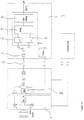
- FIG. 1 shows a block diagram for the radar method according to the invention.
- FIG. 1 shows an RF block 1 and a video / mod board 2 for an FM-CW radar sensor usual analog signal modules.
- the digital one Signal processing takes place on a DSV board 3, on the other Signal input via a cable connection 4 from the radar sensor determined analog signal of the radar scene fed is.
- On the DSV board 3, the analog signal in digitized an A / D converter 5.
- the method according to the invention used for the conversion the analog measured values of the radar sensor are inexpensive A / D converter 5 with 8-bit resolution at a sampling rate of 2 MHz.
- a level switch is to ensure dynamics of more than 50 dB implemented for the A / D converter in the process. This level change is based on the signal amplitude triggered behind the A / D converter 5. Becomes a threshold within a certain period of time from a given one Number of values exceeded, so the input side triggered an analog gain switch. At the same time, the digital signal by the same factor amplified so that the level relationships of the digital Processing remains unchanged.
- the level switching of the A / D converter 5 is in for reasons of clarity Fig. 1 not detailed.
- the R / V gates are generated via a frequency analysis of the baseband.
- the R / V information is obtained from an M * N point FFT 6 after the frequency gates have been rearranged. That is M ramps and N samples per ramp.
- blocked processing with M pieces of N-point R-FFTs and N r pieces of M-point V-FFTs takes place.
- the R-FFTs are real and form N / 2 valid values, the V-FFTs are complex.
- the advantage of this processing is that the R-gates can be processed selectively (N r ⁇ N / 2) and that less memory is required for the rotation factors of the FFTs 6.
- the FFTs 6 are double because of the clock switching known in the FM-CW method.
- the known FM-CW process also exists a short-range signal that indicates crosstalk represents from the transmitting to the receiving branch and is due to the fact that transmit and receive operations are carried out simultaneously is present.
- This signal usually blocks the 1st and 2nd gate (0 -10m); or it will be there faked an object.
- this crosstalk is compensated in two stages.
- the crosstalk signal (amount) is compensated hard;
- the crosstalk signal (amount) is estimated and the change in the signal is observed in order to detect real objects in the 1st or 2nd R gate when driving slowly, e.g. in city traffic, at traffic lights or in a traffic jam To be able to distinguish crosstalk signal.
- the R and V gates from the two FFTs become a matrix arranged in the detection 7.
- the power distribution within this R, V matrix is used to detect existing ones Objects and determination of distance and speed used.
- the detection is carried out using an adaptive CFAR threshold, separates the useful signals from the noise.
- the threshold is R-dependent designed to meet the R-dependent noise level to become.
- the value of the threshold for a given Distance for the next cycle is averaged formed over the V cells that are under in the current cycle the threshold.
- a special feature of the implemented track formation 8 is in that it does the detection without an intermediate step assigns directly to the tracks. Even lie for a point goal due to the inventive method up to nine Detections. So real objects are in the R, V matrix extended.
- the difficulty of this known lane formation lies in certain situations in deciding what "belong together" includes and sometimes complicated procedures applied to closely related detections, that belong to two real objects, for example, recognizable as such because the detections become an object can merge.
- i becomes a track j in track formation 8 calculated as probability r (i, j) by a generalized Distance dimension depends.
Abstract
Description
Die Erfindung betrifft ein Radarverfahren für eine automatische, intelligente Verkehrssteuerung (AICC) in einem KFz gemäß dem Oberbegriff des Patentanspruchs1.The invention relates to a radar method for an automatic, intelligent traffic control (AICC) in a car according to the preamble of claim 1.
Bekannte KFz-Radare sind in ihren Eigenschaften und in ihrem Aufbau wesentlich durch die Verwendung von Pulsradaren bestimmt. Dabei kommen in bekannten Systemen für die Erfassung mehrerer Meßgrößen aufwendige und kostenintensive Mehrwegesysteme zum Einsatz. Known vehicle radars are in their properties and in their Construction essentially through the use of pulse radars certainly. Here come in known systems for detection several measured variables complex and costly Reusable systems for use.
In der früher angemeldeten DE 197 32 509.2 ist ein hochauflösendes Radarverfahren beschrieben, das auf einem FM-CW-Verfahren mit Sägezahnmodulation beruht, um eine gleichzeitige Auflösung der Radarszene in Entfernung und Relativgeschwindigkeit zu erreichen. Bei diesem Verfahren wird das Radarecho an der Sendereferenz abgemischt, um das Basisbandsignal zu bilden. Das Verfahren zeichnet sich dadurch aus,
- daß das Basisbandsignal einer jeden Modulationsperiode in einem Analog-Digital-Konverter digitalisiert und mittels einer N-Punkte-Fourier-Transformation in Entfernungs-/Zeitwerte umgewandelt wird,
- daß diese Umwandlung für M zeitlich aufeinanderfolgende Modulationsperioden wiederholt wird,
- daß die ermittelten Entfernungswerte einer jeden Modulationsperiode in einer der jeweiligen Modulationsperiode zugeordneten Zeile eines zweidimensionalen Datenspeichers abgespeichert werden,
- daß die abgespeicherten Entfernungs-/Zeitwerte spaltenweise einer M-Punkte-Fourier-Transformation zur Bildung von Relativgeschwindigkeitswerten unterworfen werden und derart eine Entfernungs-/Geschwindigkeitsmatrix der beobachteten Radarszene erzeugt wird.
- that the baseband signal of each modulation period is digitized in an analog-to-digital converter and converted into distance / time values by means of an N-point Fourier transformation,
- that this conversion is repeated for M successive modulation periods,
- that the determined distance values of each modulation period are stored in a row of a two-dimensional data memory assigned to the respective modulation period,
- that the stored distance / time values are subjected to an M-point Fourier transformation in columns to form relative speed values, and a distance / speed matrix of the observed radar scene is generated in this way.
Bei dem Verfahren erfolgt im Analogteil des Radarsensors eine frequenz- und damit entfernungsabhängige Pegelkompensation bzw. mittels eines dem A/D-Wandler vorgeschalteten Antialiasingfilters eine Frequenzbegrenzung der Basisbandsignale zu höheren Frequenzen hin. Von den mit der N-Punkte-Fourier-Transformation ermittelten N Entfernungs-/Zeitwerten werden in einer Ausführungsform des Verfahrens nur NR < N/2 Werte zur nachfolgenden Signalverarbeitung abgespeichert und weiterverarbeitet. Die eingesetzte Fourier-Transformationen (z.B. die schnelle Fouriertransformation (FFT)) arbeiten mit geeigneten Datenfenstern, um Nebenzipfel bei den Auflösungszellen der Entfernungs/Geschwindigkeitsmatrix auf einen vorgebbaren Wert abzusenken.In the method, frequency and therefore distance-dependent level compensation is carried out in the analog part of the radar sensor, and frequency limitation of the baseband signals to higher frequencies by means of an anti-aliasing filter connected upstream of the A / D converter. In one embodiment of the method, only N R <N / 2 values of the N distance / time values determined using the N-point Fourier transformation are stored and processed for subsequent signal processing. The Fourier transforms used (eg the fast Fourier transform (FFT)) work with suitable data windows in order to lower secondary lobes in the resolution cells of the distance / speed matrix to a predeterminable value.
Der Erfindung liegt die Aufgabe zugrunde ein preiswertes Radarverfahren für ein AICC in einem KFz zu schaffen, das Radarsysteme mit geringem Platzbedarf ermöglicht. Das Radarverfahren soll von vorausfahrenden KFz die Entfernung, die Relativgeschwindigkeit und den Winkel erfassen und für die Verwendung in einem AICC aufbereiten.The invention has for its object an inexpensive To create a radar method for an AICC in a motor vehicle Radar systems with a small footprint enable. The radar process the distance from the vehicle in front, capture the relative speed and angle and for prepare the use in an AICC.
Diese Aufgabe wird erfindungsgemäß durch die im Patentanspruch 1 angegebenen Merkmale gelöst. Weiterbildungen der Erfindung sind in den Unteransprüchen angegeben.This object is achieved by the claim 1 specified features solved. Further training of the Invention are specified in the subclaims.
Mit dem erfindungsgemäßen Verfahren ist eine Anpassung der Auswertung an einen FM-CW-Radarsensor möglich, der gegenüber einem Pulsradarsensor preiswerter ist. Der Lösungsvorschlag betrifft eine vorteilhafte digitale Erfassung und Auswertung der Meßwerte und umfaßt mehrere Auswertungsschritte. Die Vorteile des erfindungsbemäßen Radarverfahrens sind durch eine rechenaufwandsgünstige Programmierung, durch eine Einbeziehung der Historie bei der Zuordnung Detektion <> Spur und durch eine Beherrschung von Situationen, in denen es aufgrund der Ausdehnung der Objekte in einer R,V-Matrix zu Verschmelzungen von eng benachbarten, realen Objekten kommen kann gekennzeichnet; z.B. bei einem langsamen Überholer eines vorausfahrenden PKW.With the method according to the invention, an adaptation of the Evaluation on an FM-CW radar sensor possible, the opposite a pulse radar sensor is cheaper. The proposed solution concerns an advantageous digital acquisition and Evaluation of the measured values and comprises several evaluation steps. The advantages of the radar method according to the invention are through computationally inexpensive programming, by including the history in the assignment detection <> Trace and by mastering situations, in which, due to the expansion of the objects in an R, V matrix for mergers of closely neighboring, real objects can come marked; e.g. at a slow overtaking of a car in front.
Anhand der Zeichnung wird nachstehend ein Ausführungsbeispiel der Erfindung näher erläutert. Fig.1 zeigt ein Blockschaltbild für das erfindungsgemäße Radarverfahren.An embodiment is shown below with the aid of the drawing the invention explained in more detail. 1 shows a block diagram for the radar method according to the invention.
Das in Fig.1 gezeigte Blockschaltbild zeigt mit einem HF-Block
1 und einer Video/Mod-Platine 2 die für einen FM-CW-Radarsensor
üblichen analogen Signalbausteine. Die digitale
Signalverarbeitung erfolgt auf einer DSV-Platine 3, an deren
Signaleingang über eine Kabelverbindung 4 das vom Radarsensor
ermitteltete Analogsignal der Radarszene eingespeist
ist. Auf der DSV-Platine 3 wird das Analogsignal in
einem A/D-Wandler 5 digitalisiert.The block diagram shown in FIG. 1 shows an RF block
1 and a video /
Das erfindungsgemäße Verfahren verwendet für die Umwandlung
der analogen Meßwerte des Radarsensors einen kostengünstigen
A/D-Wandler 5 mit 8-bit-Auflösung bei einer Abtastrate
von 2 MHz. Um mit dieser geringen Bitzahl die notwendige
Dynamik von mehr als 50 dB zu gewährleisten, ist eine Pegelumschaltung
für den A/D-Wandler in das Verfahren implementiert.
Diese Pegelumschaltung wird von der Signalamplitude
hinter dem A/D-Wandler 5 ausgelöst. Wird ein Schwellwert
innerhalb einer bestimmten Zeitspanne von einer vorgegebenen
Anzahl von Werten überschritten, so wird eingangsseitig
eine analoge Verstärkungsumschaltung ausgelöst.
Gleichzeitig wird das digitale Signal um den gleichen Faktor
verstärkt, so daß die Pegelverhältnisse der digitalen
Verarbeitung ungeändert bleiben. Die Pegelumschaltung des
A/D-Wandlers 5 ist aus Gründen der Übersichtlichkeit in
Fig. 1 nicht näher ausgeführt.The method according to the invention used for the conversion
the analog measured values of the radar sensor are inexpensive
A /
Beim FM-CW-Verfahren werden bekannterweise die R-/V-Tore
über eine Frequenzanalyse des Basisbandes erzeugt. Im einfachsten
Fall erhält man die R-/V-Information aus einer
M*N-Punkte FFT 6 nach einer Umsortierung der Frequenztore.
Das sind M Rampen und N Abtastwerte pro Rampe. Erfindungsgemäß
findet dahingegen eine geblockte Verarbeitung mit M
Stück N-Punkte-R-FFTs und Nr Stück M-Punkte-V-FFTs statt.
Die R-FFTs sind reell und bilden N/2 gültige Werte, die V-FFTs
sind komplex. Der Vorteil dieser Verarbeitung liegt
darin, daß die R-Tore selektiv bearbeitet werden können (Nr
< N/2) und daß weniger Speicherbedarf für die Drehfaktoren
der FFTs 6 benötigt wird. Die FFTs 6 sind wegen der im FM-CW-Verfahren
bekannten Taktumschaltung doppelt ausgeführt.In the FM-CW process, it is known that the R / V gates are generated via a frequency analysis of the baseband. In the simplest case, the R / V information is obtained from an M *
Weiterhin existiert beim bekannten FM-CW-Verfahren prinzipiell ein Signal in kurzen Entfernungen, welches das Übersprechen vom Sende- auf den Empfangszweig darstellt und dadurch bedingt ist, daß gleichzeitig Sende- und Empfangsbetrieb vorliegt. Diese Signal blockiert üblicherweise das 1. und das 2. Tor (0 -10m); bzw. es wird dadurch dort ein Objekt vorgetäuscht.In principle, the known FM-CW process also exists a short-range signal that indicates crosstalk represents from the transmitting to the receiving branch and is due to the fact that transmit and receive operations are carried out simultaneously is present. This signal usually blocks the 1st and 2nd gate (0 -10m); or it will be there faked an object.
Erfindungsgemäß wird dieses Übersprechen in zwei Stufen kompensiert .Für Veigen > 15 km/h wird das Übersprechsignal (Betrag) hart kompensiert; für Veigen < 15 km/h wird das Übersprechsignal (Betrag) geschätzt und die Änderung des Signales beobachtet, um reale Objekte im 1. oder 2. R-Tor bei langsamer Fahrt, z.B. im Stadtverkehr, an der Ampel oder im Stau, vom Übersprechsignal unterscheiden zu können.According to the invention, this crosstalk is compensated in two stages. For V eigen > 15 km / h, the crosstalk signal (amount) is compensated hard; for V eigen <15 km / h, the crosstalk signal (amount) is estimated and the change in the signal is observed in order to detect real objects in the 1st or 2nd R gate when driving slowly, e.g. in city traffic, at traffic lights or in a traffic jam To be able to distinguish crosstalk signal.
Die R- und V-Tore aus den beiden FFTs werden zu einer Matrix
in der Detektion 7 angeordnet. Die Leistungsverteilung
innerhalb dieser R,V-Matrix wird zur Detektion von vorhandenen
Objekten und Bestimmung von Entfernung und Geschwindigkeit
herangezogen. In dem erfindungsgemäßen Verfahren
erfolgt die Detektion mittels einer adaptiven CFAR-Schwelle,
die Nutzsignale vom Rauschen trennt. Die Schwelle ist
R-abhängig gestaltet, um dem R-abhängigen Rauschpegel gerecht
zu werden. Der Wert der Schwelle für eine bestimmete
Entfernung für den nächsten Zyklus wird durch Mittelung
über die V-Zellen gebildet, die im aktuellen Zyklus unter
der Schwelle liegen.The R and V gates from the two FFTs become a matrix
arranged in the
Das erfindungsgemäße Verfahren beinhaltet eine Spurbildung 8, welche die Aufgabe hat, einzelne Objekte über die Zeit zu verfolgen und sofern vorhanden, die für die Aufgabenstellung relevanten Objekte auszuwählen. Dazu sind mehrere Verfahrensschritte vorgesehen:
- die Initialisierung von Spuren;
- die Zuordnung der erfolgten Detektionen zu bestehenden Spuren ;
- die Filterung/das Update der Kennwerte (Entfernung, Geschwindigkeit und Winkel) einer Spur;
- das Löschen von Spuren, die nicht mehr mit neuen Daten versorgt werden und
- die Auswahl/die Priorisierung von bestimmten Spuren nach geeigneten Kriterien.
- the initialization of tracks;
- the assignment of the detections made to existing tracks;
- filtering / updating the parameters (distance, speed and angle) of a track;
- deleting tracks that are no longer supplied with new data and
- the selection / prioritization of certain tracks according to suitable criteria.
Ein Besonderheit der implementierten Spurbildung 8 liegt
darin, daß sie ohne einen Zwischenschritt die Detektion
direkt den Spuren zuordnet. Selbst für ein Punktziel liegen
bedingt durch das erfindungsgemäße Verfahren bis zu neun
Detektionen vor. Reale Objekte sind in der R,V-Matrix also
ausgedehnt.A special feature of the implemented
Wegen dieser Ausdehnung realer Objekte findet in bekannten Verfahren noch ein Zwischenschritt, die sog. Objektbildung statt. Diese Objektbildung faßt zusammengehörige Detektionen zusammen und berechnet für das zugehörige Objekt entsprechende Mittelwerte der Kenngrößen. Aus diesen Objekten werden dann die Spuren gebildet.Because of this expansion of real objects takes place in known ones Another intermediate step, the so-called object formation instead of. This object formation summarizes related detections together and calculated for the associated object corresponding mean values of the parameters. From these objects the tracks are then formed.
Die Schwierigkeit dieser bekannten Spurbildung liegt in gewissen Situationen darin, zu entscheiden was "zusammengehörig" beinhaltet und es müssen teilweise komplizierte Verfahren angewendet werden, um nahe zusammenliegende Detektionen, die zu beispielsweise zwei realen Objekten gehören, als solche zu erkennen, da die Detektionen zu einem Objekt verschmelzen können.The difficulty of this known lane formation lies in certain situations in deciding what "belong together" includes and sometimes complicated procedures applied to closely related detections, that belong to two real objects, for example, recognizable as such because the detections become an object can merge.
Bei der Zuordnung können Detektionen auch zu mehreren Spuren
gleichzeitig gehören. Die Zugehörigkeit einer Detektion
i zu einer Spur j wird erfindungsgemäß in der Spurbildung 8
als Wahrscheinlichkeit r(i,j) berechnet, die von einem verallgemeinerten
Abstandandsmaß abhängt.When assigning, detections can also be made to multiple tracks
belong at the same time. The affiliation of a detection
According to the invention, i becomes a track j in
Claims (2)
Applications Claiming Priority (2)
| Application Number | Priority Date | Filing Date | Title |
|---|---|---|---|
| DE19822622A DE19822622A1 (en) | 1998-05-20 | 1998-05-20 | Radar method in a motor vehicle |
| DE19822622 | 1998-05-20 |
Publications (2)
| Publication Number | Publication Date |
|---|---|
| EP0959370A2 true EP0959370A2 (en) | 1999-11-24 |
| EP0959370A3 EP0959370A3 (en) | 2000-07-19 |
Family
ID=7868398
Family Applications (1)
| Application Number | Title | Priority Date | Filing Date |
|---|---|---|---|
| EP99108990A Withdrawn EP0959370A3 (en) | 1998-05-20 | 1999-05-06 | Vehicle radar method |
Country Status (5)
| Country | Link |
|---|---|
| US (1) | US6266004B1 (en) |
| EP (1) | EP0959370A3 (en) |
| JP (1) | JPH11352216A (en) |
| DE (1) | DE19822622A1 (en) |
| IL (1) | IL129989A (en) |
Cited By (5)
| Publication number | Priority date | Publication date | Assignee | Title |
|---|---|---|---|---|
| CN104251983A (en) * | 2013-06-27 | 2014-12-31 | 成都中远信电子科技有限公司 | Portable ground surveillance radar signal processor |
| CN105548979A (en) * | 2015-12-29 | 2016-05-04 | 大连楼兰科技股份有限公司 | Car lane changing auxiliary system threshold detection method |
| CN107783084A (en) * | 2016-08-25 | 2018-03-09 | 大连楼兰科技股份有限公司 | CFAR detection and data processing platform (DPP) |
| CN107783085A (en) * | 2016-08-25 | 2018-03-09 | 大连楼兰科技股份有限公司 | The cell-average applied in CFAR detection and Data processing selects small thresholding detection method |
| CN108693531A (en) * | 2018-03-22 | 2018-10-23 | 合肥晟泰克汽车电子股份有限公司 | The processing method of automobile anti-collision radar system |
Families Citing this family (15)
| Publication number | Priority date | Publication date | Assignee | Title |
|---|---|---|---|---|
| WO2002018972A1 (en) * | 2000-08-30 | 2002-03-07 | Hitachi,Ltd. | Radar apparatus |
| DE10050278B4 (en) * | 2000-10-10 | 2005-06-02 | S.M.S., Smart Microwave Sensors Gmbh | Method and device for determining distance and relative speed of a remote object |
| JP3610052B2 (en) * | 2002-04-18 | 2005-01-12 | 三菱電機株式会社 | Radar equipment |
| JP4566572B2 (en) * | 2004-02-04 | 2010-10-20 | 三菱電機株式会社 | In-vehicle radar system |
| US20070230643A1 (en) * | 2006-03-20 | 2007-10-04 | Harris Corporation | Track State - And Received Noise Power-Based Mechanism For Selecting Demodulator Processing Path In Spatial Diversity, Multi-Demodulator Receiver System |
| US20070217555A1 (en) * | 2006-03-20 | 2007-09-20 | Harris Corporation | Knowledge-Aided CFAR Threshold Adjustment For Signal Tracking |
| US8026844B2 (en) * | 2006-06-08 | 2011-09-27 | Vista Research, Inc. | Radar visibility model |
| JP5639150B2 (en) * | 2010-03-09 | 2014-12-10 | 古河電気工業株式会社 | Pulse radar apparatus and control method thereof |
| JP5889037B2 (en) * | 2012-02-22 | 2016-03-22 | 古河電気工業株式会社 | Pulse radar equipment |
| ITTO20120417A1 (en) * | 2012-05-09 | 2013-11-10 | St Microelectronics Srl | PROCEDURE AND DEVICES FOR DEVELOPING RADAR SIGNALS, FOR EXAMPLE FOR ROAD SAFETY SYSTEMS, ITS RELATED PRODUCT |
| DE102012024999A1 (en) * | 2012-12-19 | 2014-06-26 | Valeo Schalter Und Sensoren Gmbh | Method for setting a detection threshold for a received signal of a frequency modulation continuous wave radar sensor of a motor vehicle depending on the noise level, radar sensor and motor vehicle |
| JP6384018B2 (en) * | 2014-03-25 | 2018-09-05 | 日本無線株式会社 | Automotive radar equipment |
| CN107783122B (en) * | 2016-08-25 | 2021-07-30 | 大连楼兰科技股份有限公司 | Fixed wing unmanned aerial vehicle collision avoidance system radar signal processing apparatus based on millimeter wave radar |
| JP6690593B2 (en) * | 2017-04-10 | 2020-04-28 | 株式会社デンソー | Perimeter monitoring radar device |
| US11416077B2 (en) * | 2018-07-19 | 2022-08-16 | Infineon Technologies Ag | Gesture detection system and method using a radar sensor |
Citations (3)
| Publication number | Priority date | Publication date | Assignee | Title |
|---|---|---|---|---|
| WO1995014939A1 (en) * | 1993-11-23 | 1995-06-01 | Siemens Aktiengesellschaft | Radar process and device for carrying out said process |
| DE4243527A1 (en) * | 1992-12-22 | 1996-01-25 | Daimler Benz Ag | Radar target classification system for jet aircraft |
| US5508706A (en) * | 1991-09-30 | 1996-04-16 | Trw Inc. | Radar signal processor |
Family Cites Families (2)
| Publication number | Priority date | Publication date | Assignee | Title |
|---|---|---|---|---|
| GB9410985D0 (en) * | 1994-06-01 | 1994-07-20 | Plessey Semiconductors Ltd | Radar transmitter/receivers |
| US5481268A (en) * | 1994-07-20 | 1996-01-02 | Rockwell International Corporation | Doppler radar system for automotive vehicles |
-
1998
- 1998-05-20 DE DE19822622A patent/DE19822622A1/en not_active Ceased
-
1999
- 1999-05-06 EP EP99108990A patent/EP0959370A3/en not_active Withdrawn
- 1999-05-16 IL IL12998999A patent/IL129989A/en not_active IP Right Cessation
- 1999-05-20 JP JP11140064A patent/JPH11352216A/en active Pending
- 1999-05-20 US US09/315,065 patent/US6266004B1/en not_active Expired - Fee Related
Patent Citations (3)
| Publication number | Priority date | Publication date | Assignee | Title |
|---|---|---|---|---|
| US5508706A (en) * | 1991-09-30 | 1996-04-16 | Trw Inc. | Radar signal processor |
| DE4243527A1 (en) * | 1992-12-22 | 1996-01-25 | Daimler Benz Ag | Radar target classification system for jet aircraft |
| WO1995014939A1 (en) * | 1993-11-23 | 1995-06-01 | Siemens Aktiengesellschaft | Radar process and device for carrying out said process |
Cited By (8)
| Publication number | Priority date | Publication date | Assignee | Title |
|---|---|---|---|---|
| CN104251983A (en) * | 2013-06-27 | 2014-12-31 | 成都中远信电子科技有限公司 | Portable ground surveillance radar signal processor |
| CN105548979A (en) * | 2015-12-29 | 2016-05-04 | 大连楼兰科技股份有限公司 | Car lane changing auxiliary system threshold detection method |
| CN105548979B (en) * | 2015-12-29 | 2018-03-06 | 大连楼兰科技股份有限公司 | Automobile lane change accessory system Threshold detection method |
| CN107783084A (en) * | 2016-08-25 | 2018-03-09 | 大连楼兰科技股份有限公司 | CFAR detection and data processing platform (DPP) |
| CN107783085A (en) * | 2016-08-25 | 2018-03-09 | 大连楼兰科技股份有限公司 | The cell-average applied in CFAR detection and Data processing selects small thresholding detection method |
| CN107783084B (en) * | 2016-08-25 | 2020-11-17 | 大连楼兰科技股份有限公司 | Constant false alarm detection and data processing platform |
| CN107783085B (en) * | 2016-08-25 | 2020-11-17 | 大连楼兰科技股份有限公司 | Unit average selection threshold detection method applied to constant false alarm rate detection and data processing |
| CN108693531A (en) * | 2018-03-22 | 2018-10-23 | 合肥晟泰克汽车电子股份有限公司 | The processing method of automobile anti-collision radar system |
Also Published As
| Publication number | Publication date |
|---|---|
| JPH11352216A (en) | 1999-12-24 |
| DE19822622A1 (en) | 1999-11-25 |
| IL129989A0 (en) | 2000-02-29 |
| IL129989A (en) | 2004-01-04 |
| US6266004B1 (en) | 2001-07-24 |
| EP0959370A3 (en) | 2000-07-19 |
Similar Documents
| Publication | Publication Date | Title |
|---|---|---|
| EP0959370A2 (en) | Vehicle radar method | |
| EP3175256B1 (en) | Method for classifying an object in an area surrounding a motor vehicle, driver assistance system and motor vehicle | |
| EP1554602B1 (en) | Method for measuring distances and speeds of several objects by means of an fmcw radar | |
| DE69816687T2 (en) | Method and device for range ambiguity resolution, in particular for frequency hopping radar | |
| DE102009057191A1 (en) | Method for uniquely determining a distance and / or a relative speed of an object, driver assistance device and motor vehicle | |
| EP1764630A1 (en) | Method of determining the size of a parking place | |
| DE102007043535A1 (en) | FMCW radar locating device and corresponding FMCW radar locating method | |
| EP0860712A2 (en) | Device and method for environment adaptive object classification | |
| DE102010030289A1 (en) | Radar sensor and method for operating a radar sensor | |
| EP0225428A2 (en) | Method for the recognition of edge structures in a picture signal | |
| DE19953790A1 (en) | Object detection system for cars has a multiple beam FMCW radar sensor mounted on the car which measures the distance and speed of reflecting objects | |
| DE102017101763A1 (en) | Method for determining at least one object information of at least one object which is detected by a radar system, in particular of a vehicle, radar system and driver assistance system | |
| EP1636608B1 (en) | Signal evaluation method for use in a sar/mti pulse radar system | |
| DE3621661A1 (en) | METHOD FOR DETECTING A DESTINATION | |
| DE19649618A1 (en) | Method and device for automatic classification of objects | |
| DE2800195A1 (en) | SYSTEM FOR AUTOMATIC SHIP COLLISION PREVENTION | |
| DE102018202903A1 (en) | Method for evaluating measurement data of a radar measurement system using a neural network | |
| DE102011051971A1 (en) | Method for determining parameter for correlation of two objects, involves transmitting electromagnetic signals series with modulated frequencies, and transmitting another electromagnetic signals series with modulated frequencies | |
| DE102018121851B3 (en) | Method for determining at least one object information of at least one object and for transmitting useful data with a radar system and radar system | |
| DE102019130295A1 (en) | Method for operating a distance sensor of a vehicle with adaptation of a transmission signal as a function of a classification of an object, computing device and sensor device | |
| DE2822492A1 (en) | DEVICE FOR THE INDEPENDENT SPEED LIMITATION OF VEHICLES, IN PARTICULAR MOTOR VEHICLES | |
| DE102020126179A1 (en) | Method for operating a radar system, radar system and vehicle with at least one radar system | |
| DE2143637C3 (en) | Pulse distance measuring receiver with long echo and echo accumulation elimination | |
| DE102022127989A1 (en) | Method for operating a detection device with disturbance treatment using an artificial neural network | |
| DE19540928A1 (en) | Driverless transport positioning method for factory or warehouse |
Legal Events
| Date | Code | Title | Description |
|---|---|---|---|
| PUAI | Public reference made under article 153(3) epc to a published international application that has entered the european phase |
Free format text: ORIGINAL CODE: 0009012 |
|
| AK | Designated contracting states |
Kind code of ref document: A2 Designated state(s): AT CH DE FR GB IT LI NL SE |
|
| AX | Request for extension of the european patent |
Free format text: AL;LT;LV;MK;RO;SI |
|
| PUAL | Search report despatched |
Free format text: ORIGINAL CODE: 0009013 |
|
| AK | Designated contracting states |
Kind code of ref document: A3 Designated state(s): AT BE CH CY DE DK ES FI FR GB GR IE IT LI LU MC NL PT SE |
|
| AX | Request for extension of the european patent |
Free format text: AL;LT;LV;MK;RO;SI |
|
| 17P | Request for examination filed |
Effective date: 20000804 |
|
| AKX | Designation fees paid |
Free format text: AT CH DE FR GB IT LI NL SE |
|
| RAP1 | Party data changed (applicant data changed or rights of an application transferred) |
Owner name: DAIMLERCHRYSLER AG |
|
| RAP1 | Party data changed (applicant data changed or rights of an application transferred) |
Owner name: DAIMLERCHRYSLER AG |
|
| STAA | Information on the status of an ep patent application or granted ep patent |
Free format text: STATUS: THE APPLICATION IS DEEMED TO BE WITHDRAWN |
|
| 18D | Application deemed to be withdrawn |
Effective date: 20061201 |